Article

Assessment of Structure and Properties Homogeneity after Repairing of a Nickel-Based Superalloy Product by the Electron Beam Additive Technology

Institute of Strength Physics and Materials Science, Siberian Branch of Russian Academy of Sciences, 634055 Tomsk, Russia
*
Author to whom correspondence should be addressed.
Crystals 2022, 12(10), 1400; https://doi.org/10.3390/cryst12101400
Submission received: 30 August 2022 / Revised: 27 September 2022 / Accepted: 30 September 2022 / Published: 3 October 2022
(This article belongs to the Special Issue Mechanical and Microstructural Characterization of Superalloys)

Abstract

:
Repairing damaged products made of nickel-based superalloys is an urgent task because replacing them with new products is a costly and time-consuming process. The present work considers the method of electron-beam additive manufacturing as an approach to the repair process. First of all, the initial product was produced by layer-by-layer deposition. Hereon, a part of the surface was removed, and then several more layers were deposited. Thus, three areas were considered in the work: initial, transitional, and repaired areas. Each of the formed regions was defect-free. It was found that the transition region was difficult to identify since it did not differ in structural-phase composition from the initial and repaired regions. It is shown that the complex thermal history consisting of periodic thermal exposure and repeated melting of the newly crystallized layers does not lead to the formation of defects and undesirable phases. Moreover, in all three regions, there is a redistribution of the chemical element content of the γ′ and γ phases towards an increase in the mismatch of their lattice parameters. The mechanical properties of the transition and repaired regions are not significantly different from the initial area.

1. Introduction

Nickel-based superalloys have excellent mechanical and physical properties such as long-term strength, creep and corrosion resistance at high temperatures. This makes them in high demand in an aircraft engine design. During the last few decades, requirements to properties of materials used in the production of aircraft engines have increased significantly. This led to the necessity to change the chemical composition of the alloys, increasing the content of refractory elements, to develop new technologies and approaches to obtaining products, as well as to carry out more precise control of the structural-phase composition. At present, additive manufacturing is being considered as an alternative technology for the conventional production of metal products (casting and milling cut) [1,2,3]. To date, there are a sufficient number of methods of metal additive manufacturing, which can be classified according to various characteristics. For example, in the process of forming a product, melting of the feedstock material may or may not occur [4]. In the case of melting, as a rule, the feedstock is fed directly into the focus of the heat source, or selective melting in a powder bed is implemented. The feedstock can be wire, rod, powder, or foil. In the case of melting-based processes, electron beam, laser beam, or electric arc are used as heat sources. Methods of additive product formation without the melting of the feedstock material include ultrasonic additive manufacturing, friction stir additive manufacturing, and cold spraying [4]. The most popular materials in the aerospace industry used in additive manufacturing are nickel-based superalloys, as well as cobalt, copper, titanium, aluminum alloys, and stainless steel. In addition, alloys based on refractory elements such as tungsten, molybdenum, tantalum, and niobium can be used.
The phase composition of superalloys is quite complex, and many modern works are devoted to its research, for example [5,6,7]. The structural basis of heat-resistant superalloys, which determines their properties, are two phases. One is the disordered solid solution of the alloying elements in nickel (γ-phase). The other is an ordered phase (superstructural type L12) based on the intermetallic compound Ni3Al (commonly referred to as γ′-phase). Both phases have FCC crystal lattices. The microstructure of heat-resistant alloys is represented by nanosized or submicrocrystalline γ′-phase precipitations of various morphologies (from spherical to cuboidal), surrounded by interlayers of γ-phase [7]. In the process of prolonged high-temperature testing (or due to operating conditions) the γ′- phase coalesces and takes an elongated form, resulting in a raft structure [8]. Depending on the alloying system, heat treatment modes, and mechanical action, superalloys may contain (in addition to the main γ/γ′-hardening phases) different types of carbides (MeC, Me6C, Me23C6), geometrically closed packed phases (η, δ) and topologically closed packed phases (σ, μ, Laves phase) [9,10]. Some of these secondary phases have similar chemical compositions and insignificant differences in crystal lattice parameters. For example, δ- and γ″-phases with the same Ni3Nb chemical composition are formed in alloys with a niobium content greater than 5 wt% [11]. In addition, the same phase can have different morphology depending on the state of the material.
It should be noted that during the additive processes of forming metal products (including those made of heat-resistant superalloys) there are additional factors that affect the formation of phases in the material of products. Such factors include complex thermal history, periodic remelting and cyclic thermal exposure, the presence of multiple boundaries of layers and melt baths, different ratios of temperature gradients and solidification rates in different areas of the product, features of heat removal from the melt bath, product geometry and 3D printing strategy. All of the above makes the process of phase composition identification quite a complex and time-consuming task that requires taking into account many influencing factors and involves a variety of research methods.
The use of expensive materials imposes significant restrictions on the possibility of producing new products to replace those damaged in service or in production. From this point of view, damaged parts repairing methods are often used [12,13,14]. The present work assesses the possibility of repairing a nickel-based superalloy product (damaged in the manufacturing process, before the heat treatment stage) by wire-feed electron beam additive manufacturing, as well as establishing the structural homogeneity and material properties of the repaired additive product.

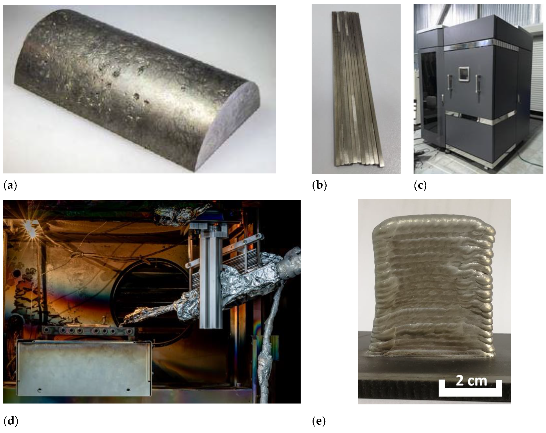
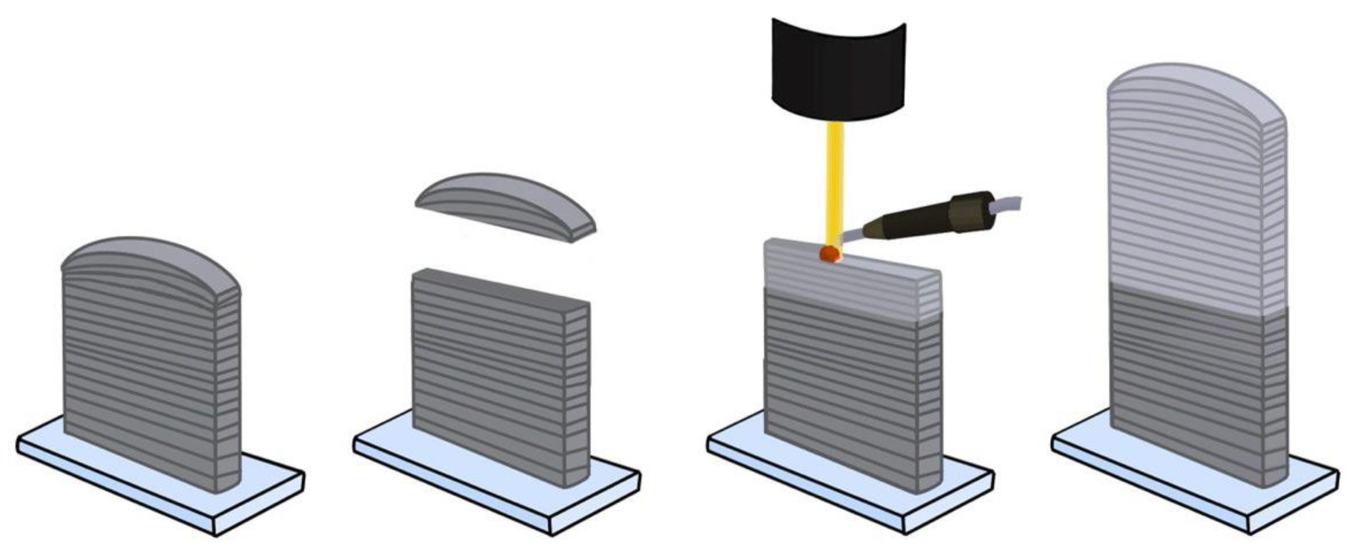
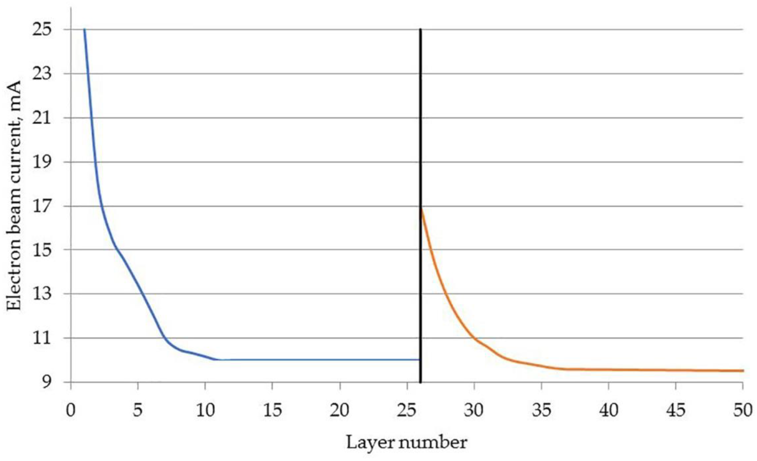
2. Materials and Methods

The heat-resistant nickel-based superalloy ZhS6U (or K465) was used as the feedstock material, the chemical composition of which is presented in Table 1. This alloy belongs to the early nickel-based superalloys with an equiaxial structure. As it is impossible to obtain a wire from this alloy, the ingot of the initial material was cut into rods of 3 × 3 × 170 mm3 on the DK-7725 electric discharged machine, and then the rods were subjected to mechanical grinding to remove erosion products.
Prepared rods were loaded into the feeding system of the wire-feed electron beam additive manufacturing setup developed in the ISPMS SB RAS (Tomsk, Russia). The process of additive product formation was as follows. The rod was fed into the focus of the electron beam, which led to its heating and melting. After the formation of a melt bath, the worktable began to move, thus forming a material layer. When the formation of the layer was completed, the process stopped, the system lifted to a predetermined height, and it moved to the beginning of the formed layer. Then the entire process was repeated, resulting in a product in the form of a 40 × 50 × 8 mm3 wall, consisting of 26 layers deposited. Figure 1 shows the main stages of the process of obtaining a product from the heat-resistant superalloy ZhS6U by wire-feed electron beam additive technology.
The following assumptions were made to justify the studies. The additive product received mechanical damage during operation. The damage is localized in the upper quarter (at a distance of ¾ of the product’s height from its base and above) of the product.
To simulate the repairing of the damaged product geometry, the upper part of the product with “damages” with a total height of 9.5 mm was removed by means of electrical discharge machining (see Figure 2). The cut surface was mechanically cleaned of electroerosion products and then a similar additive wall consisting of 26 layers was built. The final dimensions of the repaired additive product were about 70 × 51 × 8 mm3. A significant height allowance of the repaired product was created to conduct subsequent studies to identify the features of the structure and mechanical properties of the product material in the initial and repaired conditions, including the transition region. Figure 2 shows the scheme of the implemented process.
For the additive formation of such products, the parameters of the wire-feed electron beam manufacturing process achieved during previous studies were used [16,17]. When forming the initial and repaired walls, the invariable parameters were the speed of the working table movement—20 mm/min and the accelerating voltage—30 kV. The variable parameter was the beam current, shown in Figure 3.
In this work, the task of heat treatment of the material of the finished additive product was not set. Earlier studies [18] have shown that heat treatment (including homogenization and aging) of additive products made of ZhS6U superalloy does not improve the mechanical properties of the material at room temperature.
Studies of the structure, phase composition, and mechanical properties were carried out in three locations, in the area of the initial product, in the transition area, and the area of repaired material. Studies of the macrostructure were conducted on polished and etched metallographic cross-sections using optical microscopy on the Altami Met 1S device (Altami Ltd., St. Petersburg, Russia). Etching was carried out in Marble solution (CuSO4—8 g, HCl—40 mL, H2O—40 mL). Studies of the structure, phase, and chemical composition were carried out by scanning electron microscopy on the device “LEO EVO 50” (Zeiss, Jena, Germany). A JEOL JEM-2100 transmission electron microscope (Tokyo Boeki Ltd., Tokyo, Japan) was used to study the microstructure and identify the phase composition. Samples for TEM studies were prepared as thin foils by ion polishing on Model 1051 TEM Mill (Fischione Instruments Inc., Export, PA, USA). The mechanical properties were evaluated by static uniaxial tension on an UTC-110M-100 testing machine (Testsystems, Russia). For mechanical tests, dog-bone-type specimens with an effective section of 2.5 × 2.5 mm2 and a gauge length of 12 mm were cut. The specimens were cut at an angle of 60° relative to the substrate with an inclination in the direction of the electron beam movement. This angle was chosen so that the tensile axis of the samples coincided with the direction of dendrite growth. Samples were cut into three pieces from three areas: initial, transitional, and repaired. The test was conducted at room temperature (RT). The average value of three parallel tests was taken as the result of mechanical tests for each area (Figure A1).

3. Results and Discussions
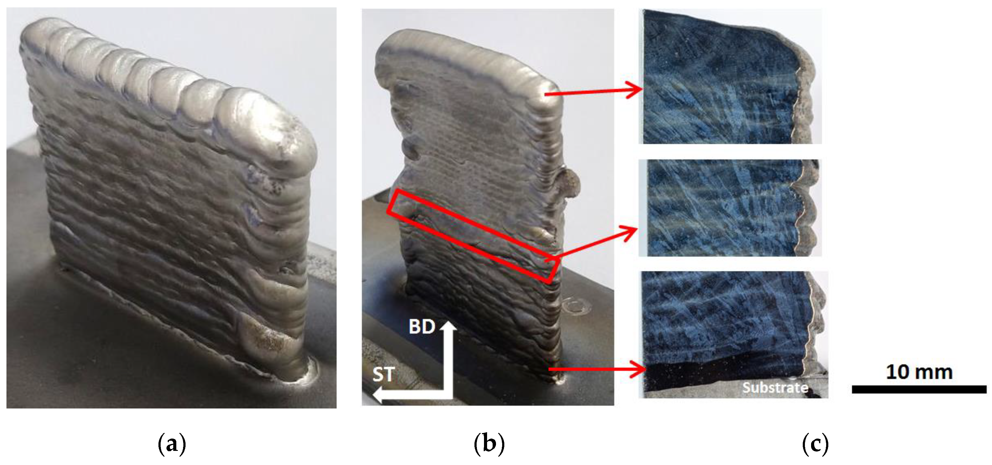
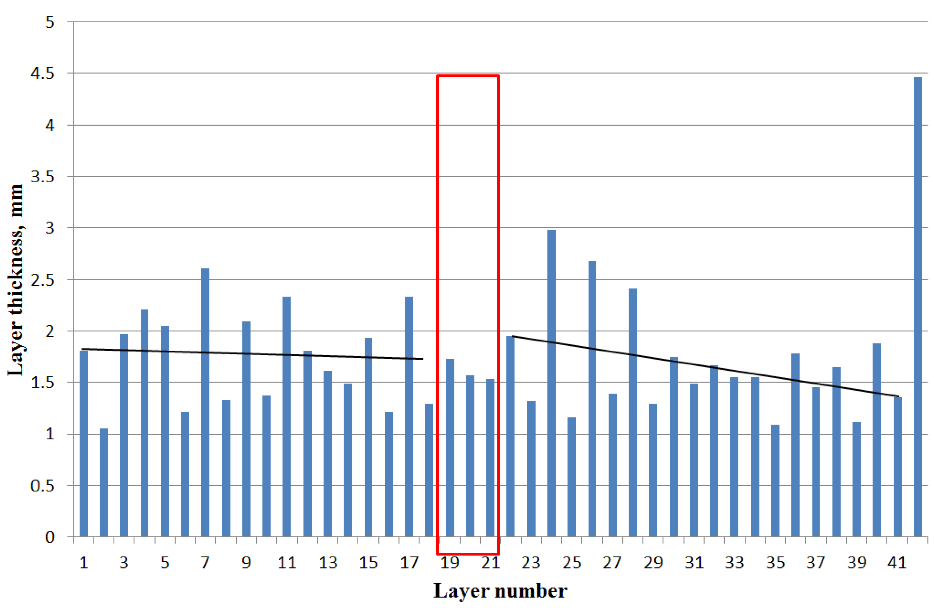
3.1. Macrostructure

The general view of the initial and the repaired product is shown in Figure 4. As can be seen, the surface of the product is corrugated, the boundaries of layers and melt baths are clearly visible. On the repaired part there are drops of melted metal, which violate the specified geometry of the formed product. It should also be noted that the macrostructure images (Figure 4c) do not reveal any macro defects in the form of pores, cracks, and fissures.
It has to be noted that the alternation of layer thicknesses is visually observed (Figure 5). This effect is particularly evident in the repaired area. In the initial product, the larger layers have an average thickness of 2.15 ± 0.25 mm, and the thinner layers 1.37 ± 0.23 mm. In the repaired area large and fine layers have an average thickness of 2.03 ± 0.49 and 1.32 ± 0.16 mm, respectively. The revealed peculiarity of the product morphology is due to the fact that it takes half a bar of the initial material to form one layer. Before the formation of each odd layer (except the first) there was a technological operation of resetting stocks of the consumed rod and supplying a new rod, which led to an increase in the interval between the end of the formation of the previous layer and the beginning of the next from 3 to 16 s. Increasing the delay leads to a greater decrease in the temperature of the last formed layer. The material with a lower temperature was re-melted to a smaller depth, which led to an increase in its thickness. Analysis of the results previously carried out and the present study did not reveal the effect of the difference in layer thickness on the mechanical properties of the product material. Therefore, the introduction of a compensating delay between the acts of layer formation seems unnecessary since it will inevitably lead to an increase in the entire process of additive growing. At the same time, it is worth noting that there are studies, for example [19], in which the authors introduce delays in the additive product formation process to control the size of the melt bath. This eventually leads to successful control of the given product geometry. It is also worth noting that the thickness of the last layer (not re-melted) is ~4.5 mm. Based on this and the data in Figure 5, it can be assumed that each layer, except for the last one, is re-melted 2–3 times.
Figure 6 shows images of the structure of the three studied regions. As can be seen, all three areas are characterized by directional growth of dendrite colonies with some slope in the direction of 3D printing (shown in Figure 6 as ST—scanning trajectory). To describe the structural features, the main structural characteristics of the product material were quantified. The characteristics of materials with a dendritic structure are the average primary dendrite arm spacing (PDAS) and axial misorientation of dendrite colonies [20,21,22].

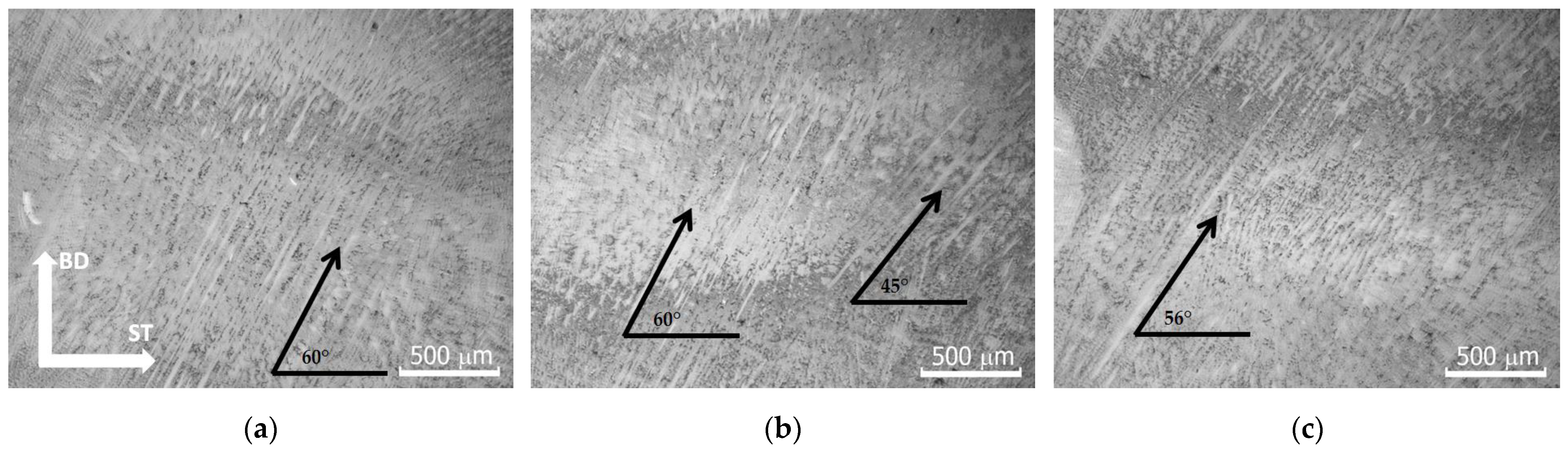
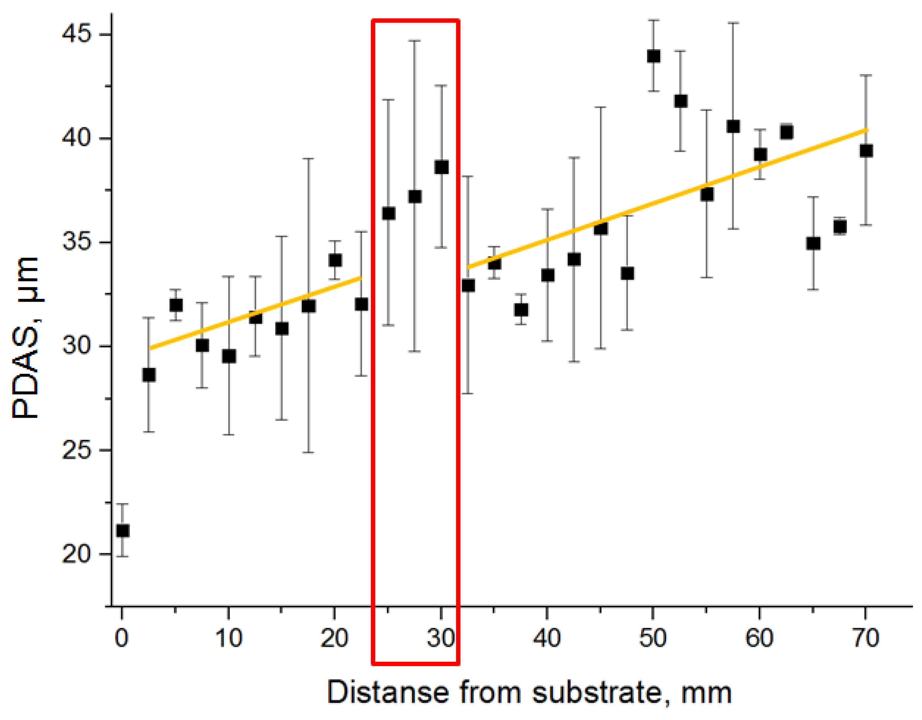
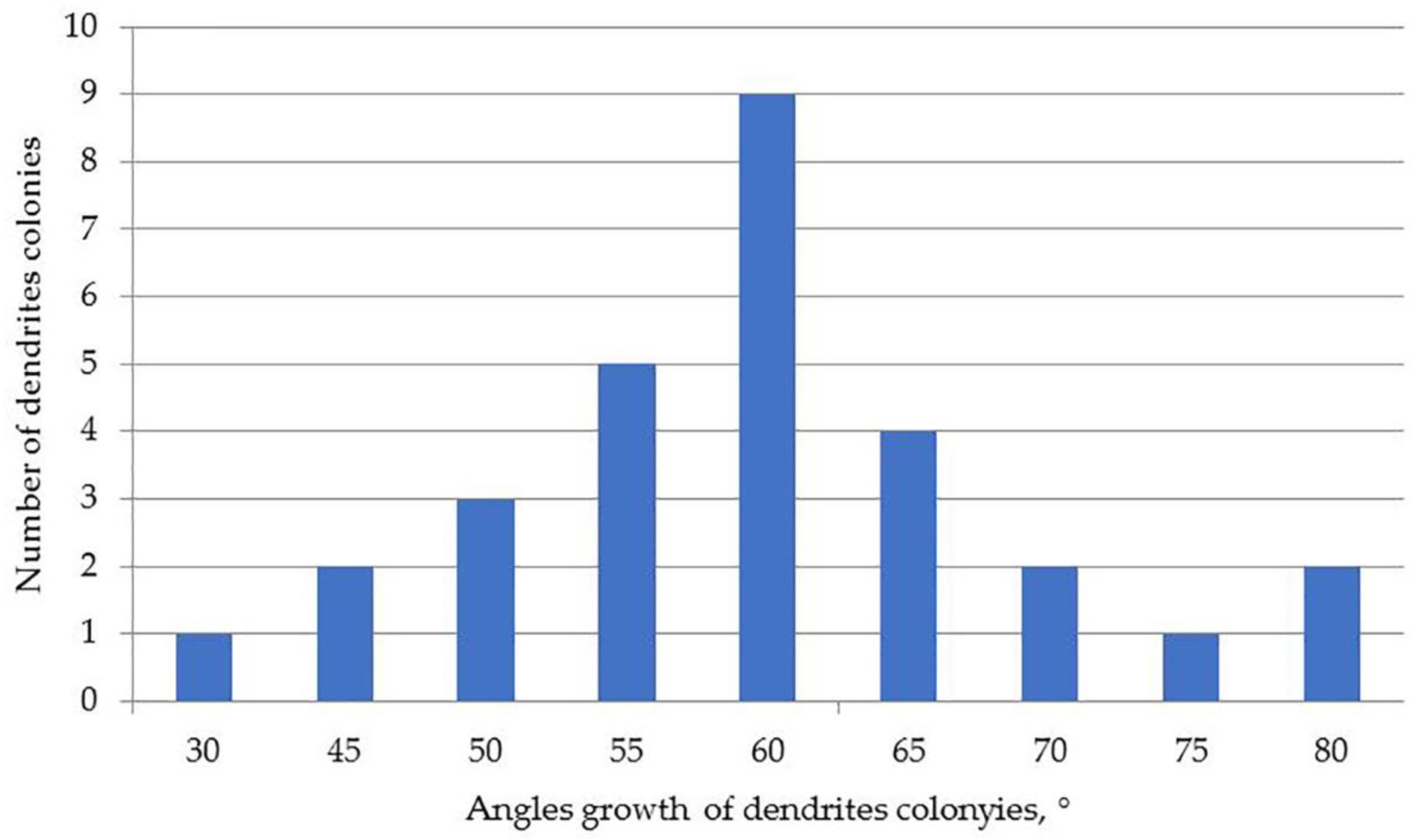
3.2. Dendritic Structure

Figure 7 shows the dependence of the PDAS on the height of the product. The graph shows that the PDAS near the substrate has the smallest value, which indicates the most effective heat removal in this area, realized by achieving the greatest value of the temperature gradient directed into the substrate. The largest temperature gradient at the border with the substrate is due to the fact that the thermal conductivity of the substrate material (austenitic steel) is greater than that of the additively formed product, as well as the fact that a larger volume of material is available for heat removal. A similar thermal history was observed in the use of the laser heat source in [23]. Moreover, as it moves away from the substrate, there is a gradual increase in PDAS from 28.7 ± 2.7 µm (not including the area bordering the substrate) to 34.2 ± 0.9 µm. In the transition region, there is a stepwise increase in PDAS up to 37.3 ± 5.2 μm. This stepwise change in the PDAS in the transition region can be explained by the fact that at the beginning of the additive formation of the repaired region it is necessary to increase the heat input (Figure 3) because the formation takes place on the material at room temperature. In this case, the volume of material available for heat dissipation is much smaller than when forming on a solid substrate, which leads to the enlargement of the PDAS. As can be seen in Figure 3, the heat dissipation conditions normalize after the additive formation of three layers and the PDAS returns to a monotonic increase. In the repaired region, the increase in PDAS continues monotonously, but the homogeneity decreases. Thus, in this area, the lowest value of PDAS is 31.8 ± 0.7 μm, and the highest is 44.0 ± 1.7.
As discussed above, in all regions, the dendrites grow in colonies with some tilt in the direction of 3D printing (Figure 6). The smallest tilt angle of dendrite colonies relative to the substrate is 30.0 ± 1.4°, and the largest is 79.3 ± 5.9°. No regularities could be detected when analyzing changes in the angle of inclination of dendritic colonies along the product height. However, the distribution by growth angle indicates that the greatest number of dendrite colonies grow at an angle of ~60° to the substrate (see Figure 8).

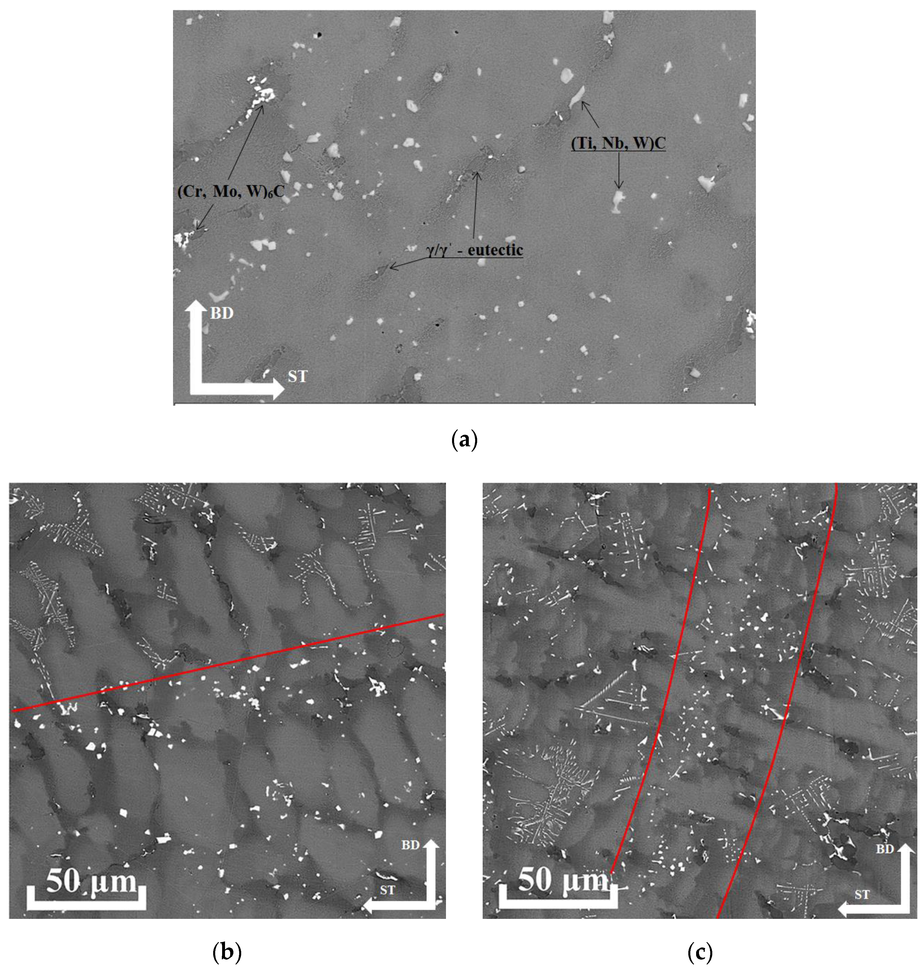
3.3. Microstructure and Phase Composition

Secondary phases in the form of carbides and γ/γ′-eutectics are uniformly distributed between the dendrite axes in the dendritic material structure of the formed product (Figure 9). This structure is observed both in the initial and repaired regions. The transition region does not reveal any obvious structural differences from the base material. For this reason, it is quite difficult to identify this region visually, as well as using optical and scanning electron microscopy (without conducting statistical processing of structural characteristics measurement results).
The characteristic image of the material microstructure in Figure 9 shows the following structural elements: dendrite axes, interdendritic space, dark phases—eutectics, as well as two types of carbides—less contrast in the form of individual particles (presumably MeC) and more contrast stretched irregular morphology (presumably Me6C). In addition, it is visible that the dendrites and the interdendritic space are represented by a mixture of γ/γ′-phases (the γ-phase is a layer between the γ′-phase cuboids), with the γ′-phase cuboids enlarging in the interaxial space. As can be seen from the above images (Figure 9b,c), at the boundaries of melt baths and layers secondary phases (carbides) are crushed, and their morphology becomes closer to equiaxial, while in the volume of the material, carbides have a shape known as “Chinese script” [24,25]. It can also be seen that γ/γ′-eutectics are more often found in the volume of the material, rather than at the boundaries of the layers. It is also worth noting that scanning electron microscopy studies of the structure revealed no micro defects in the form of cracks at the boundaries of dendritic axes or pores.
The energy dispersive analysis of various structural elements and phases showed the following (Table 2). The dendrites’ chemical composition corresponded to the initial alloy’s grade composition (with the exception of molybdenum and niobium segregated in the interaxial space) and remained unchanged for each investigated area. The composition of the γ/γ′-eutectics was also unchanged. The selections of the less contrasting phase were enriched in titanium, niobium, and tungsten; the second phase (more contrasting) was enriched in chromium, molybdenum, and tungsten. On this basis, we could assume that the first phase was MeC carbide and the second was Me6C carbide. In the repaired region MeC carbides were more enriched in titanium, niobium and tungsten, and Me6C carbides, on the contrary, contained less molybdenum and tungsten.
The heat-resistant properties of nickel-based superalloys were determined primarily by the γ′ phase. On this basis, it was necessary to study the changes in this phase’s properties (size and chemical composition). Table 3 shows the size of cuboidal precipitations (Figure 10) of γ′-phase in three characteristic areas. As seen in Table 3, in the initial material and the transition region, the size of cuboids was larger than in the repaired region, which was associated with a larger electron beam current (Figure 3) required to form a defect-free structure. The tertiary γ′-phase particles with a size of 10–20 nm were also observed (upper right corner of Figure 10).

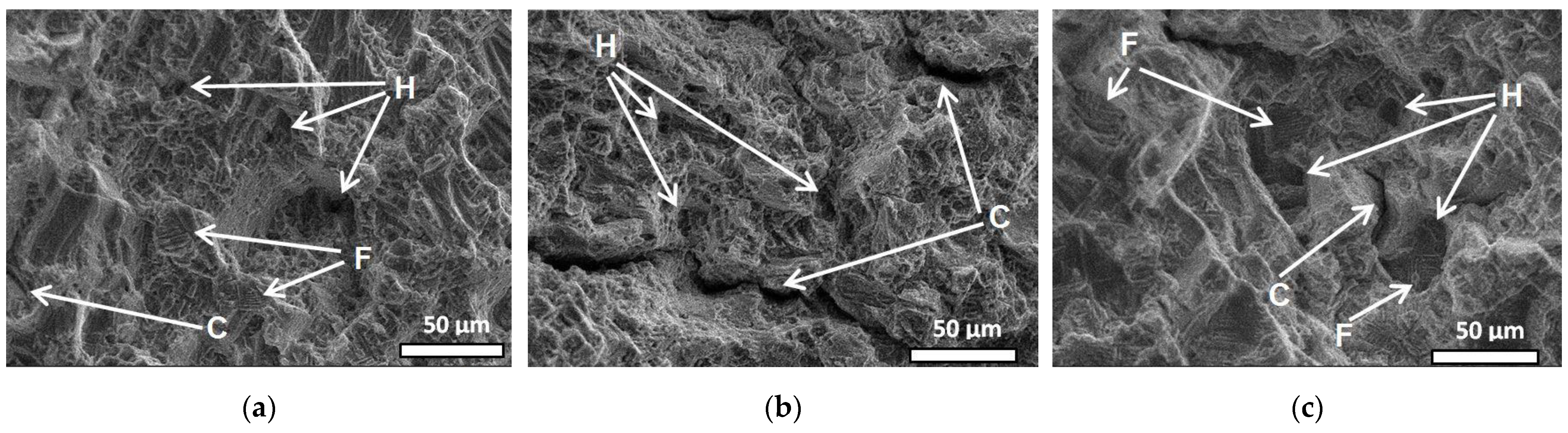
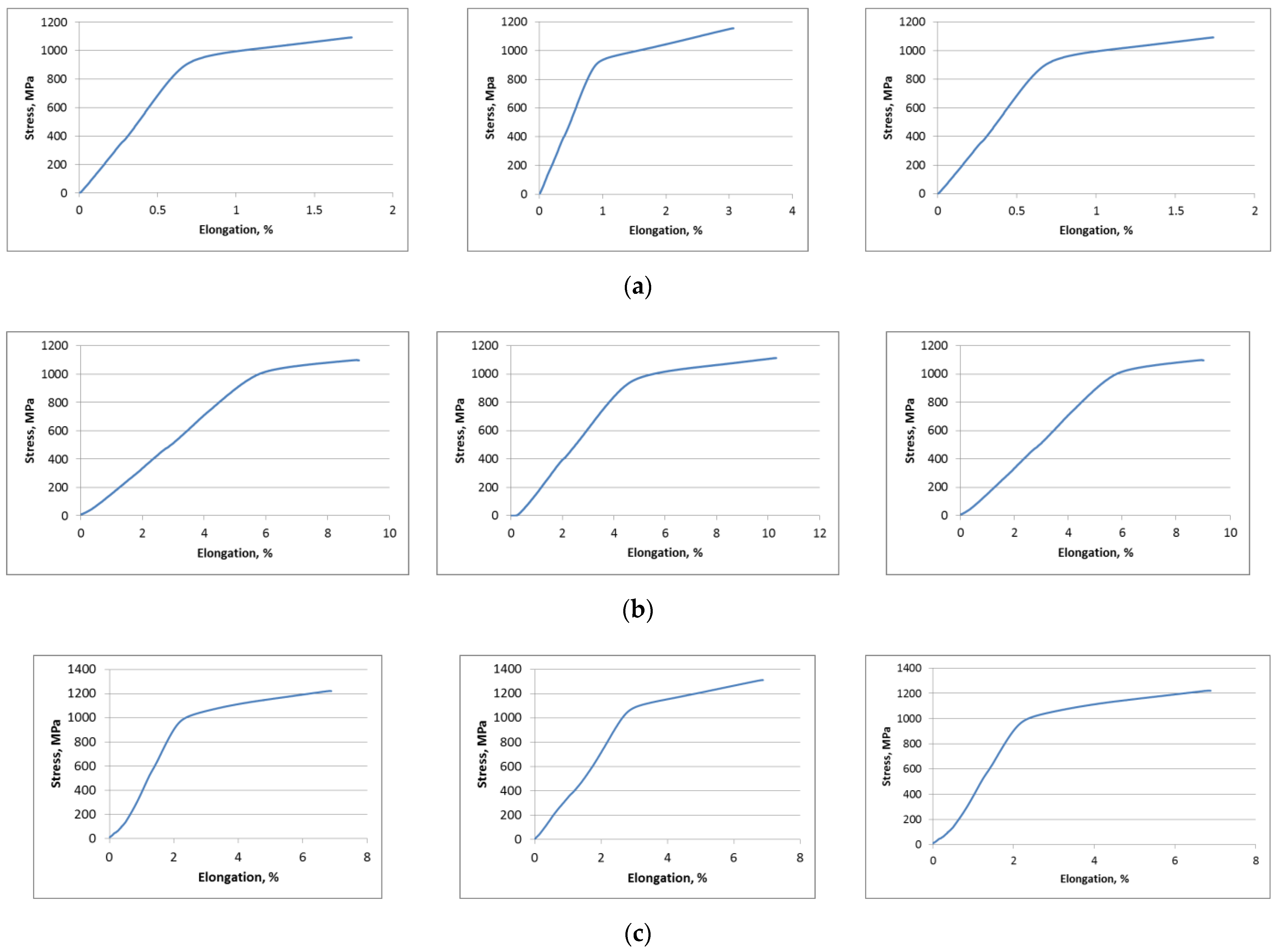
3.4. Mechnical Properties and Fractography

Table 4 shows the data on the mechanical properties of the additively formed product. The repaired region had the highest value of the ultimate tensile strength (~1312 ± 94 MPa), which was due to the smallest size of γ′-phase cuboids (Table 3). As can be seen from Table 3 and Table 4 and Figure 7, the mechanical properties correlated more with the size of the γ′-phase, while the PDAS experienced a constant increase with distance from the substrate. From this, it can be assumed that the mechanical properties are more influenced by the fine structure (γ′-phase). It should also be noted that the initial area had the lowest relative elongation (2.6 ± 0.7 %). This can be explained by the fact that the static tensile specimens were cut along the direction of dendrite axis growth. In the initial product (the area closest to the substrate) the directional growth was most pronounced (in this case, the greatest number of dendrite axes coincides with the direction of stressing), due to the largest temperature gradient. Consequently, in this case, most of the dendrites are located along the sample stress direction. As a result, the direction of dendrite axis boundaries most often coincides with the direction of applied stress, which, in turn, reduces the relative elongation [26].
The analysis of the fracture surfaces showed the following. In all regions, there is a mixed fracture mechanism, which is a combination of micropore fusion and intergranular (in our case, interdendritic) fracture. However, the regions differ in the proportion of the components. Thus, in the initial region, the fracture surface reveals, in fact, equal proportions of interdendritic fracture dimples and facets, as well as a few open cracks perpendicular to the fracture surface (Figure 11a). In Figure 11, some of the dimples, facets, and cracks are shown by arrows labeled “H”, “F” and “C”, respectively. As can be seen in Figure 11b, the transition area reveals only dimples and multiple cracks. Whereas in the repaired area on the fracture surface, dimples and facets of the interdendritic fracture and open cracks perpendicular to the fracture surface are revealed in equal proportions (see Figure 11c). At the same time, interdendritic fracture facets are observed at the bottom of some pits. The differences in the ratio of ductile to brittle components of the mixed fracture are reflected and correlate well with the results of the mechanical tests (Table 4).

4. Conclusions

In the course of the study, a simulation of repairing the mechanically damaged area of an additive nickel-based superalloy product was performed.
It was shown that the transition region contains no macro-defects and is hardly detectable at macro and micro levels. It testifies to the structural-phase homogeneity in the whole array of the product, both in the initial and repaired regions, including the transition region.
Quantitative analysis of the results of detailed structural studies has shown that in the transition region, the product material structure is represented by larger dendrites compared to the initial product and the repaired region. Also, an enlargement of γ′-phase precipitations in the transition region is observed. Both phenomena are associated with an increase in the resulting heat input in the transition region.
The structure-phase composition of this region is unchanged and corresponds to the raw material:
(a)
dendrite axes standing of secondary and tertiary nanoscale and submicrocrystalline γ′-phase cuboidal separations with interlayers of γ-phase.
(b)
interdendritic space, also consisting of γ-phase and larger (within the submicrocrystalline size) cuboidal γ′-phase precipitations.
(c)
secondary phases in the form of γ′/γ -eutectics and carbides of two types (MeC and Me6C).
The composition of the dendrite axes in the three regions has no significant differences, indicating that the microsegregation degree of the alloying elements is preserved. The chemical composition of the γ-phase of the additively formed product differs from the raw cast material in that it shows an increased content of chromium and tungsten, which is a favorable effect that increases the mismatch between the crystal lattice parameters of the γ′ and γ phases.
The mechanical properties and fracture character of all three regions are approximately the same, except that the highest ultimate tensile strength is achieved in the repaired region (1312 ± 94 MPa), and the lowest relative elongation is in the initial product (2.6 ± 0.7%). Based on the achieved results, we can conclude that the method of electron-beam additive technology is suitable as a repairing technology for damaged products from heat-resistant nickel-based superalloys since the homogeneity of structure and properties is preserved.

Author Contributions

Conceptualization, D.G. and S.F.; methodology, S.F. and S.N.; validation, D.G. and S.F.; formal analysis, D.G. and S.F.; investigation, V.U., T.K. and A.C.; resources, E.K. and V.R.; data curation, S.F. and V.R.; writing—original draft preparation, D.G.; writing—review and editing, S.F.; visualization, T.K.; supervision, V.R.; project administration, E.K.; funding acquisition, E.K. and V.R. All authors have read and agreed to the published version of the manuscript.

Funding

The structure, phase composition and mechanical properties study was funded by RFBR, project number No. 20-32-90010. Works on obtaining samples for research and optimization of electron-beam additive process were performed according to the Government research assignment for ISPMS SB RAS, project FWRW-2022-0004.

Data Availability Statement

The data presented in this study are available on request from the corresponding author.

Acknowledgments

Investigations were carried out using the equipment of the Nanotekh Regional Core Facility Centre of the Institute of Strength Physics and Materials Science SB RAS.

Conflicts of Interest

The authors declare no conflict of interest.

Appendix A

Figure A1. Raw stress-strain diagrams for the three regions under study—(a) initial material, (b) transition area, (c) repaired area. Three samples were tested for each area.
Crystals 12 01400 g0a1

References

  1. Pan, H.; Dahmen, T.; Bayat, M.; Lin, K.; Zhang, X. Independent effects of laser power and scanning speed on IN718’s precipitation and mechanical properties produced by LBPF plus heat treatment. Mater. Sci. Eng. A 2022, 849, 143530. [Google Scholar] [CrossRef]
  2. Li, Y.; Liang, X.; Peng, G.; Lin, F. Effect of heat treatments on the microstructure and mechanical properties of IN738LC prepared by electron beam powder bed fusion. J. Alloys Compd. 2022, 918, 165807. [Google Scholar] [CrossRef]
  3. Wang, Y.; Roy, S.; Choi, H.; Rimon, T. Cracking suppression in additive manufacturing of hard-to-weld nickel-based superalloy through layer-wise ultrasonic impact peening. J. Manuf. Process. 2022, 80, 320–327. [Google Scholar] [CrossRef]
  4. Gradl, P.; Tinker, D.C.; Park, A.; Mireles, O.R.; Garcia, M.; Wilkerson, R.; Mckinney, C. Robust metal additive manufacturing process selection and development for aerospace components. J. Mater. Eng. Perform. 2022, 31, 6013–6044. [Google Scholar] [CrossRef]
  5. Zhang, S.; Wang, L.; Lin, X.; Yang, H.; Huang, W. The formation and dissolution mechanisms of Laves phase in Inconel 718 fabricated by selective laser melting compared to directed energy deposition and cast. Compos. B Eng. 2022, 239, 109994. [Google Scholar] [CrossRef]
  6. Theska, F.; Buerstmayr, R.; Liu, H.; Lison-Pick, M.; Street, S.R.; Primig, S. Influence of grain boundary precipitation and segregation on cracking of cast and wrought superalloys containing B and Zr. Mater. Charact. 2022, 187, 111881. [Google Scholar] [CrossRef]
  7. Wang, H.; Liu, D.; Wang, J.; Yang, Y.; Rao, H.; Wang, H.; Nah, J.; Wang, L. Study on the evolution of the γˈ phase and grain boundaries in nickel-based superalloy during interrupted continuous cooling. Crystals 2021, 11, 1464. [Google Scholar] [CrossRef]
  8. Yu, Z.; Wang, X.; Yang, F.; Yue, Z.; Li, J. Review of γ’ rafting behavior in nickel-based superalloys: Crystal plasticity and phase-field simulation. Crystals 2020, 10, 1095. [Google Scholar] [CrossRef]
  9. Doğu, M.N.; Davut, K.; Obeidi, M.A.; Yalçın, M.A.; Gu, H.; Low, T.; Ginn, J.; Brabazon, D. Recrystallization and grain growth kinetics of IN718 manufactured by laser powder bed fusion. J. Mater. Res. Technol. 2022, 19, 4242–4257. [Google Scholar] [CrossRef]
  10. Luo, H.; Li, X.; Pan, C.; Qu, S.; Jiang, C.; He, P.; Zeng, K. Interfacial characterization and mechanical properties of additively manufactured IN718/CoNiCrAlY laminate. Mater. Sci. Eng. A 2022, 850, 143578. [Google Scholar] [CrossRef]
  11. Silva, C.; Song, M.; Leonard, K.; Wang, M.; Was, G.; Busby, J. Characterization of alloy 718 subjected to different thermomechanical treatments. Mater. Sci. Eng. A 2017, 691, 195–202. [Google Scholar] [CrossRef]
  12. Chen, Y.; Yang, C.; Fan, C.; Wang, M. The influence of solution temperature on microstructure evolution and mechanical properties of ATI 718Plus repaired by wire and arc additive manufacturing. Mater. Sci. Eng. A 2022, 852, 143641. [Google Scholar] [CrossRef]
  13. Ci, S.; Liang, J.; Li, J.; Zhou, Y.; Sun, X. Microstructure and tensile properties of DD32 single crystal Ni-base superalloy repaired by laser metal forming. J. Mater. Sci. Technol. 2020, 45, 23–34. [Google Scholar] [CrossRef]
  14. Liu, G.; Du, D.; Wang, K.; Pu, Z.; Chang, B. Epitaxial growth behavior and stray grains formation mechanism during laser surface re-melting of directionally solidified nickel-based superalloys. J. Alloys Compd. 2021, 853, 157325. [Google Scholar] [CrossRef]
  15. Kablov, E.N.; Petrushin, N.V.; Parfenovich, P.I. Design of castable refractory nickel alloys with polycrystalline structure. Met. Sci. Heat Treat. 2018, 60, 106–114. [Google Scholar] [CrossRef]
  16. Gurianov, D.A.; Fortuna, S.V.; Nikonov, S.Y.; Moskvichev, E.N.; Kolubaev, E.A. Heat input effect on the structure of zhs6u alloy products produced by wire-feed electron-beam additive manufacturing. Russ. Phys. J. 2021, 64, 1415–1421. [Google Scholar] [CrossRef]
  17. Kolubaev, E.A.; Rubtsov, V.E.; Chumaevsky, A.V.; Astafurova, E.G. Scientific Approaches to Micro-, Meso- and Macrostructural Design of Bulk Metallic and Polymetallic Materials by Wire-Feed Electron-Beam Additive Manufacturing. Phys. Mesomech. 2022; 25, (in-press). [Google Scholar] [CrossRef]
  18. Gurianov, D.A.; Fortuna, S.V.; Nikonov, S.Y.; Chumaevskii, A.V. Influence of Post Heat Treatment on Additively Manufactured Nickel-Based Superalloy Structure. AIP Conf. Proc. 2022, 2509, 020085. [Google Scholar] [CrossRef]
  19. Errico, V.; Campanelli, S.L.; Angelastro, A.; Dassisti, M.; Mazzarisi, M.; Bonserio, C. Coaxial Monitoring of AISI 316L Thin Walls Fabricated by Direct Metal Laser Deposition. Materials 2021, 14, 673. [Google Scholar] [CrossRef]
  20. Liu, Y.; Wang, Y.; Savinov, R.; Shi, J. Epitaxial growth of a single-crystal nickel-based superalloy during laser melting with high-power flat-top laser. Opt. Laser Technol. 2021, 144, 10744. [Google Scholar] [CrossRef]
  21. Alhuzaim, A.; Imbrogno, S.; Attallah, M.M. Controlling microstructural and mechanical properties of direct laser deposited Inconel 718 via laser power. J. Alloys Compd. 2021, 872, 159588. [Google Scholar] [CrossRef]
  22. Zhang, J.; Lou, L. Directional solidification assisted by liquid metal cooling. J. Mater. Sci. Technol. 2007, 23, 289–300. [Google Scholar]
  23. Campanelli, S.L.; Angelastro, A.; Posa, P. Daurelio, G. Fiber laser surface remelting of a nickel-based superalloy by an integrated rectangular laser spot. Opt. Lasers Eng. 2018, 111, 42–49. [Google Scholar] [CrossRef]
  24. Wang, X.; Huang, T.; Yang, W.; Yue, Q.; He, C.; Qu, P.; Zhang, J.; Liu, L. Effect of withdrawal rate on precipitation characteristics of MC-type carbides in a nickel-based directionally solidified superalloy with high Re content. Vacuum 2021, 183, 109800. [Google Scholar] [CrossRef]
  25. Han, K.; Wang, H.; Shen, L.; Zhang, B. Analysis of cracks in the electron beam welded joint of K465 nickel-base superalloy. Vacuum 2018, 157, 21–30. [Google Scholar] [CrossRef]
  26. Shi, D.; Dong, C.; Yang, X. Constitutive modeling and failure mechanisms of anisotropic tensile and creep behaviors of nickel-base directionally solidified superalloy. Mater. Des. 2013, 45, 663–673. [Google Scholar] [CrossRef]
Figure 1. Technological process of obtaining a product from the superalloy ZhS6U by wire-feed electron beam additive technology. (a)—Initial ingot; (b)—rods after cutting and polishing; (c)—laboratory EBAM setup; (d)—rods loaded into the feeding system; (e)—obtained product sample.
Crystals 12 01400 g001
Figure 2. Schematic of the repair process using electron-beam additive technology.
Crystals 12 01400 g002
Figure 3. Changes in electron beam current during layer deposition. Blue line—formation of the initial wall, red line—formation of the repaired wall.
Crystals 12 01400 g003
Figure 4. General view of the initial (a) and the repaired (b) product, macrostructure of the product material in the longitudinal section (c). BD—build direction, ST—scanning trajectory. The closed red line shows the transition region.
Crystals 12 01400 g004
Figure 5. Changes in layer thickness depending on the layer number. The closed red line shows the transition region. Black lines—linear approximation.
Crystals 12 01400 g005
Figure 6. Material structure in initial (a), transitional (b) and repaired (c) areas. The black arrows show the angle of growth of the dendritic axes relative to the scanning trajectory. BD—building direction, ST—scanning strategy.
Crystals 12 01400 g006
Figure 7. Dependence of the primary dendrite arms spacing on the height of the product. The closed red line highlights the transition region. The orange lines show the linear approximation.
Crystals 12 01400 g007
Figure 8. Distribution of dendritic colonies growth angles.
Crystals 12 01400 g008
Figure 9. Microstructure of the product made of ZhS6U alloy after electron-beam additive process (a); (b)—layer boundary (red line); (c)—melt bath boundary (red line).
Crystals 12 01400 g009
Figure 10. Secondary γ′-phase precipitations in the repaired region.
Crystals 12 01400 g010
Figure 11. Fracture surface images. (a)—initial product, (b)—transition area, (c)—repaired area. “H”—hole, “F”—facet, “C”—crack.
Crystals 12 01400 g011
Table 1. Chemical composition of ZhS6U (K465) superalloy [15].
CrCAlTiWNb
8.0–9.50.13–0.25.1–6.02.0–2.99.5–11.00.8–1.2
MoCoFeNiOther (Si, S, Mn, P, Ce, Zr, B, Pb, Bi, Y)
1.2–2.49.0–10.5≤1Base≤0.93
Table 2. Chemical composition of different structural-phases elements (at.%).
AlTiCrCoNiNbMoW
Dendrite axis
Initial area11.002.4410.1010.4460.520.431.153.92
Transitional area10.972.7410.6710.5160.080.141.103.79
Repaired area11.812.3210.6410.5659.43-0.634.61
γ/γ′—eutectic
Initial area12.313.899.469.5160.240.781.012.80
Transitional area12.783.388.779.4960.510.511.133.43
Repaired area12.084.619.099.5260.120.860.972.72
MeC—carbides
Initial area3.2533.415.864.1024.0213.010.615.75
Transitional area4.5833.924.904.0621.6714.76-16.11
Repaired area1.7941.244.532.3314.0317.81-18.87
Me6C—carbides
Initial area5.053.935.145.213.63-15.0722.01
Transitional area4.693.4823.026.3031.85-13.4917.17
Repaired area4.773.9824.316.9434.62-10.1115.27
Table 3. The average size of γ′-phase precipitations, nm.
Initial AreaTransitional AreaRepaired Area
150.1 ± 37.5163.6 ± 49.1143.9 ± 35.0
Table 4. Mechanical properties of additively formed product sample (each value is an average of three results presented in Appendix A).
σB, MPaσ0.2, MPaδ, %
Initial area1105 ± 331019 ± 622.6 ± 0.7
Transitional area1099 ± 1021015 ± 688.9 ± 0.9
Repaired area1312 ± 941085 ± 886.8 ± 0.4
Publisher’s Note: MDPI stays neutral with regard to jurisdictional claims in published maps and institutional affiliations.

