Article

The Effect of Nickel Contents on the Microstructure Evolution and Toughness of 800 MPa Grade Low Carbon Bainite Deposited Metal

1
Shenyang National Laboratory for Materials Science, Institute of Metal Research, Chinese Academy of Sciences, Shenyang 110016, China
2
School of Materials Science and Engineering, University of Science and Technology of China, Shenyang 110016, China
*
Author to whom correspondence should be addressed.
Crystals 2021, 11(6), 709; https://doi.org/10.3390/cryst11060709
Submission received: 19 May 2021 / Revised: 9 June 2021 / Accepted: 15 June 2021 / Published: 21 June 2021
(This article belongs to the Special Issue Advances of Welding Materials)

Abstract

:
In this work, three deposited metals with different nickel (Ni) contents were produced by active gas metal arc welding (GMAW) in order to explore the influence of Ni on the microstructure evolution and toughness of 800 MPa grade low carbon bainite deposited metal. The results showed that microstructure of the deposited metals mainly consisted of lath bainite, lath martensite, coalesced bainite (CB), and retained austenite (RA), and that the toughness was closely related to two factors: CB and RA. RA in deposited metal could improve the toughness, while the CB would deteriorate the toughness of deposited metal. As the Ni content increased, a large amount of CB was generated in the deposited metals. The RA content increased from 1.5% to 5.7% with the content of Ni increasing from 5.5% to 6.5%. However, the RA content did not increase when the Ni content increased from 6.5% to 7.5%. Additionally, the smallest control unit of toughness in 800 MPa grade low carbon bainite deposited metals is the Bain Packet (BP) from the perspective of crystallography characteristics. This work provided a reference for the chemical composition design of 800 MPa grade steel welding consumables and showed that the toughness of the deposited metal could be improved effectively by increasing the RA content while suppressing the formation of CB.

1. Introduction

The steel adopted for marine applications requires a combination of excellent mechanical properties under a harsh service environment and accepted weldability [1,2]. Welding is an essential technology in the manufacturing process of marine applications. Active gas metal arc welding (GMAW) is a high production efficiency, low cost welding process compared to gas shielded tungsten arc welding (GTAW). Morever, comapared to submerged arc welding (SAW), GMAW is more adaptable during site operation. Therefore, GMAW is always the preferred choice for thick plate welding in marine engineering. At present, with chemical composition optimization and thermo-mechanical control processing (TMCP), advanced marine engineering steel with martensite or bainite as the main microstructure can achieve an excellent combination of high strength and toughness [3]. However, as the yield strength increases to the 800 MPa level, the research on the high strength and accepted toughness of welding consumables is lagging relatively behind. With the diversification of the service environment, the requirements for the mechanical properties of deposited metal are becoming higher and more stringent, the most important of which is low temperature toughness. How to improve the strength of deposited metal while obtaining accepted toughness has attracted a lot of attention in recent years [4,5,6,7,8,9].
The mechanical properties of deposited metal mainly depend on the welding process and welding consumables. Under the conditions of the GMAW welding process, the adjustment of the chemical composition of the welding consumables is adopted to improve the mechanical properties of the deposited metal. Nickel (Ni) is an alloying element that is often regarded for improving the toughness of metal materials [6]. A series of excellent work has been conducted to explore the effect mechanism of Ni on the toughness of the base metal and deposited metal. The effect of Ni on low temperature toughness is always explained by influencing the transformation austenite products [4,5,9], and the content or shape of retained austenite (RA) [6,9,10]. According to previous research, when the content of Ni increases from 0% to 6%, the hardenability of deposited metal increases, and the microstructure changes from acicular ferrite, granular bainite, and lath bainite to lath martensite [4]. Moreover, the content as well as the shape of RA is significantly affected by Ni content. Not only does the content of RA increase but the morphology of RA also changes from discontinuous film to continuous film as the Ni content increases from 3% to 9% [9]. Moreover, the influence mechanism of Ni in the high-strength deposited metal is quite different from the base metal. The microstructure of deposited metal is mainly composed of bainite or martensite when the strength of the deposited metal reaches 800 MPa level, and coalesced bainite (CB) is often found in the high-strength deposited metal. Many researchers hold the point that CB in deposited metal would seriously deteriorate the toughness, but some researches have pointed out that CB (regarded as “well-tempered martensite”) can release the stress concentration and can be positive for toughness [11]. Moreover, the formation of CB is closely related to the content of alloying elements, such as Ni and manganese (Mn) [11,12,13,14]. CB is always found in high-strength deposited metal, meanwhile CB can also be found in high-strength steel imposed to external stress during the transformation process of bainite [11,13,15,16]. There are two necessary criteria for the generation of CB: adequate space and sufficient driving force [12]. Additionally, bainite ferrite laths that can be coalesced always have a close crystallographic orientation [13]. The crystallographic characteristics essentially depend on the nucleation and growth behaviors of the bainite ferrite laths. Bainite ferrite laths can not only nucleate at the prior austenite grain boundary but can also nucleate at the side of existing bainite ferrite laths. As such, the nucleation method has an important influence on the crystallographic characteristics of bainite. The formation mechanism of CB and its effect on toughness need further exploration. It can be seen that the research on the influence of Ni on the microstructure evolution and toughness of high-strength deposited metal is lacking.
Through the above description, the effect of Ni on the microstructure evolution and toughness of 800 MPa grade deposited metal is more complicated. In this work, three kinds of high strength deposited metal with different Ni contents (5.5%, 6.5%, and 7.5%) were prepared. The role of CB and RA on the toughness of 800 MPa grade low carbon bainite deposited metal was investigated systematically. Through detailed investigation, it provided reference for the chemical composition design of 800 MPa grade steel welding consumables.

2. Materials and Methods

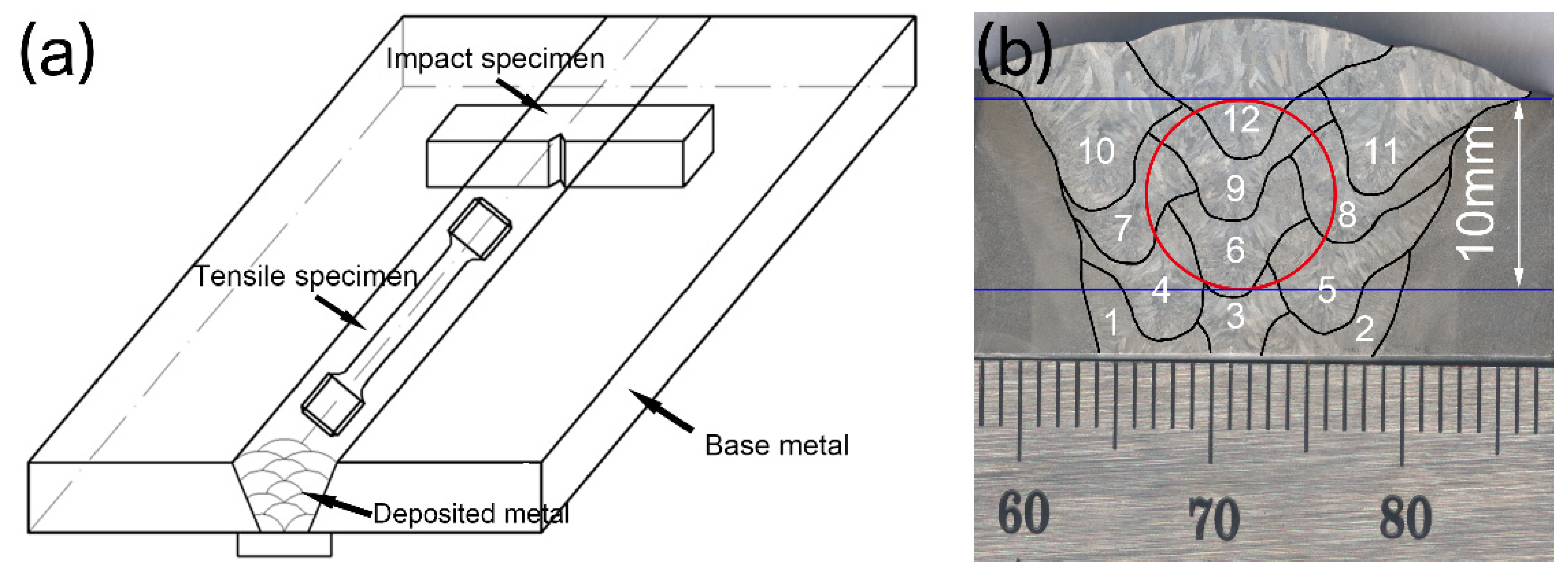
2.1. Materials Preparation

Deposited metals were prepared with an automatic GMAW machine TA1400 made by Panasonic (Tangshan, China), and the schematic diagram was shown in Figure 1. The base metal adopted an A517GrQ marine steel plate with the dimensions of 350 mm × 100 mm × 15 mm, and a butt joint with a single V-type groove was adopted to ensure full penetration. Three kinds of welding consumables with different Ni contents were adopted. Table 1 showed the chemical compositions of A517GrQ and the deposited metals. Additionally, the deposited metals with Ni contents of 5.5%, 6.5% and 7.5% are denoted as Ni5.5, Ni6.5, and Ni7.5, respectively. The welding parameters used in this experiment are indicated in Table 2.

2.2. Mechanical Testing

After welding, the specimens were taken from the deposited metals for the mechanical properties test, and the specimen location is shown in the Figure 1. Additionally, the red circle represents the sampling location of the tensile specimen, and the two blue lines represent the sampling location of the impact specimen. The specimens used for tensile testing were prepared alone in the welding direction with a gauge diameter of 5 mm and a gauge length of 25 mm, according to Chinese standards GB/T 8110–2008. The tensile testing was carried out by a Z150 electronic tension machine made by Zwick (Ulm, Germany), with a crosshead speed from 0.45 to 12 mm/min at room temperature (RT). The Charpy V-notch impact testing specimens with dimensions of 10 mm × 10 mm × 55 mm were prepared with the V-notch perpendicular to the welding direction, according to Chinese standards GB/T 8110–2008. The Charpy impact energy was measured by the SANS-ZBC2452-C impact test machine (Guangdong, China) at RT, −20 °C, and −60 °C. Furthermore, the fracture surface of the impact testing specimens was observed in order to explore the fracture pattern. In addition, the cross-section was analyzed for the investigation of the second crack propagation pathway.

2.3. Microstructure Characterization

In order to investigate the relationship between microstructure and toughness, the column zone in the last welding pass of the deposited metals was adopted for microstructure observation. The specimens used for the optical microscope (OM, Axio Lab.A1) (Baden-Württemberg, Germany), scanning microscope (SEM, FEI Inspect F50 and FEI QUANTA 450) (Hillsboro, OR, USA), and electron probe microanalysis (EPMA, EPMA-1610) (Kyoto, Japan), were prepared by being mechanically ground using emery paper up to 2000# and then polished with diamond paste up to 1.5 μm, and were finally etched using 4% nital. In order to distinguish the microstructure component of the deposited metals, Lepera etchant was used to etch the deposited metals [17]. Lepera etchant is a metallographic color etchant, and it has been successfully used in differentiating bainite and martensite. Additionally, the RA content was analyzed using X-ray diffraction (XRD, SmartLab) (Tokyo, Japan), with a Cu X-ray source. The scanning angle was between 40° and 102°, with a step of 0.02°. The specimen used for XRD analysis was prepared using electrochemical polishing after mechanical polishing in order to remove the residual stress. An in situ high temperature laser confocal scanning microscope (LCSM, VL2000DX-SVF17SP&15FTC) (Yokohama, Japan) was adopted to detect the transformation temperature of bainite.
A ZEISS MERLIN Compact SEM (Baden-Württemberg, Germany), was employed to collect the electron backscattering diffraction (EBSD) maps to measure the crystallographic orientation features of the deposited metals at 20 kV with a 150 nm step size (the analysis of crystallographic characteristics of the second crack was competed with a 300 nm step size). All of the EBSD data were analyzed by the HKL Channel 5 and ARPGE software [18,19]. The specimens used for EBSD investigation were adopted metallographic specimens without solution etching, followed by etching with an ion etching machine.
Characterization of the microstructure morphology was carried out with a transmission electron microscope (TEM, FEI Tecnai Spirit T12 and FEI Talos F200X) (Hillsboro, OR, USA), operating at 120 kV and 200 kV. The thin-foil specimens were used for TEM observation, which were machined to 3 mm in diameter and ground to approximately 50 μm in thickness. The specimens were then prepared by twin-jet electropolishing in a solution of 10% perchloric acid and 90% ethyl alcohol at −25 °C under an applied potential of 25 V.

3. Results and Discussion

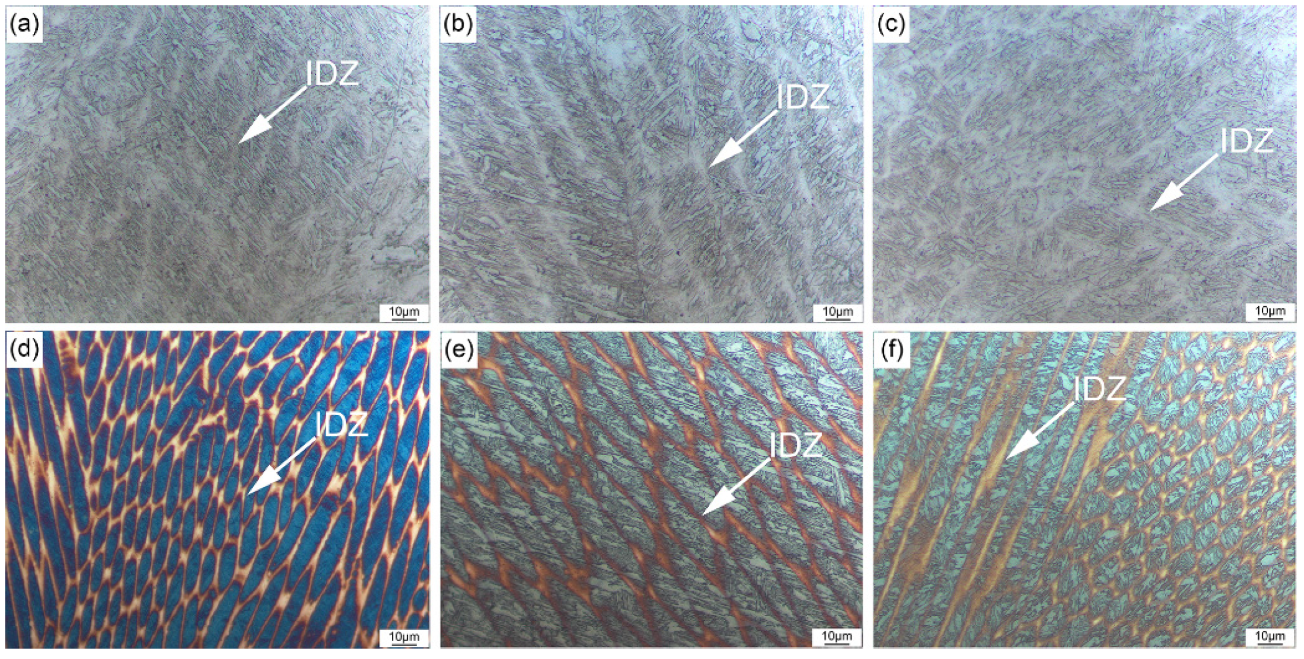
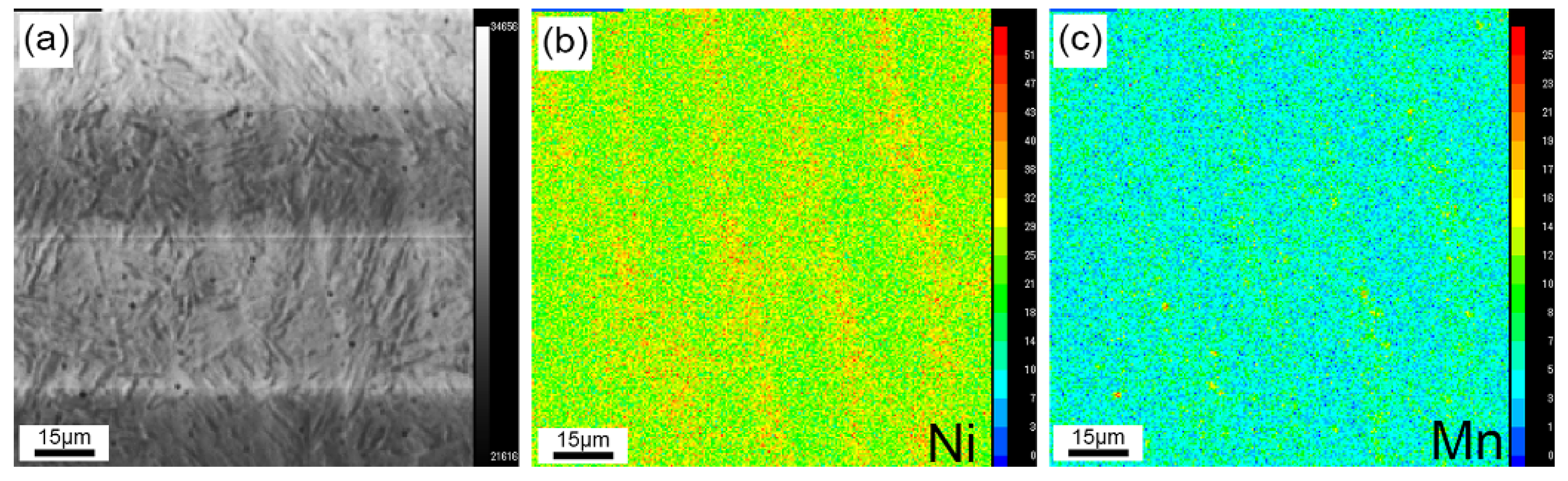
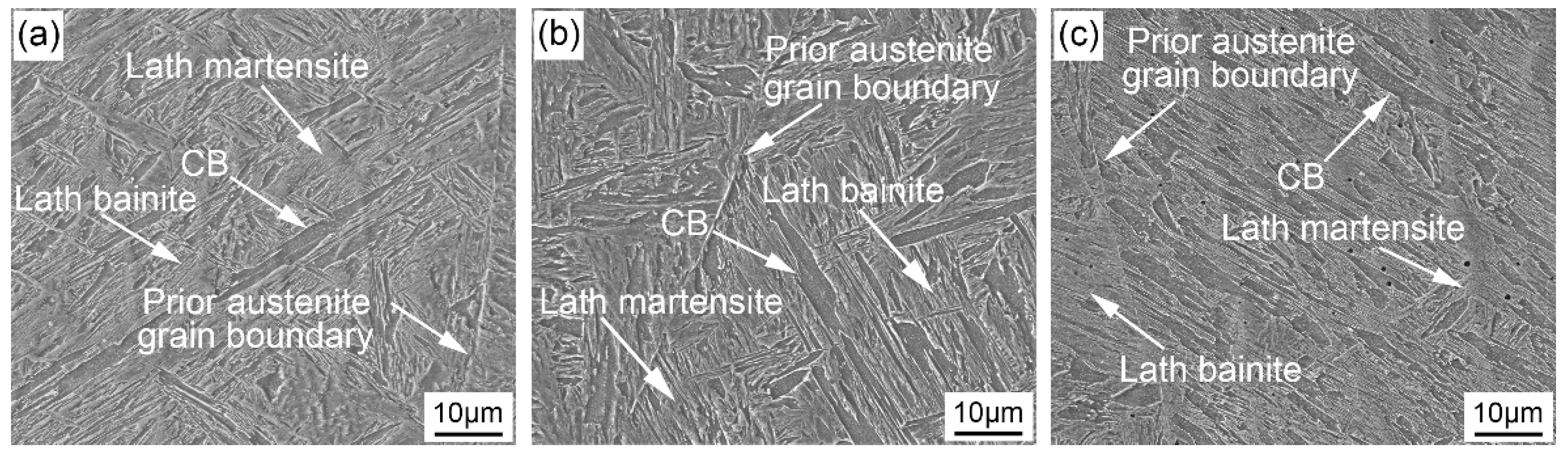
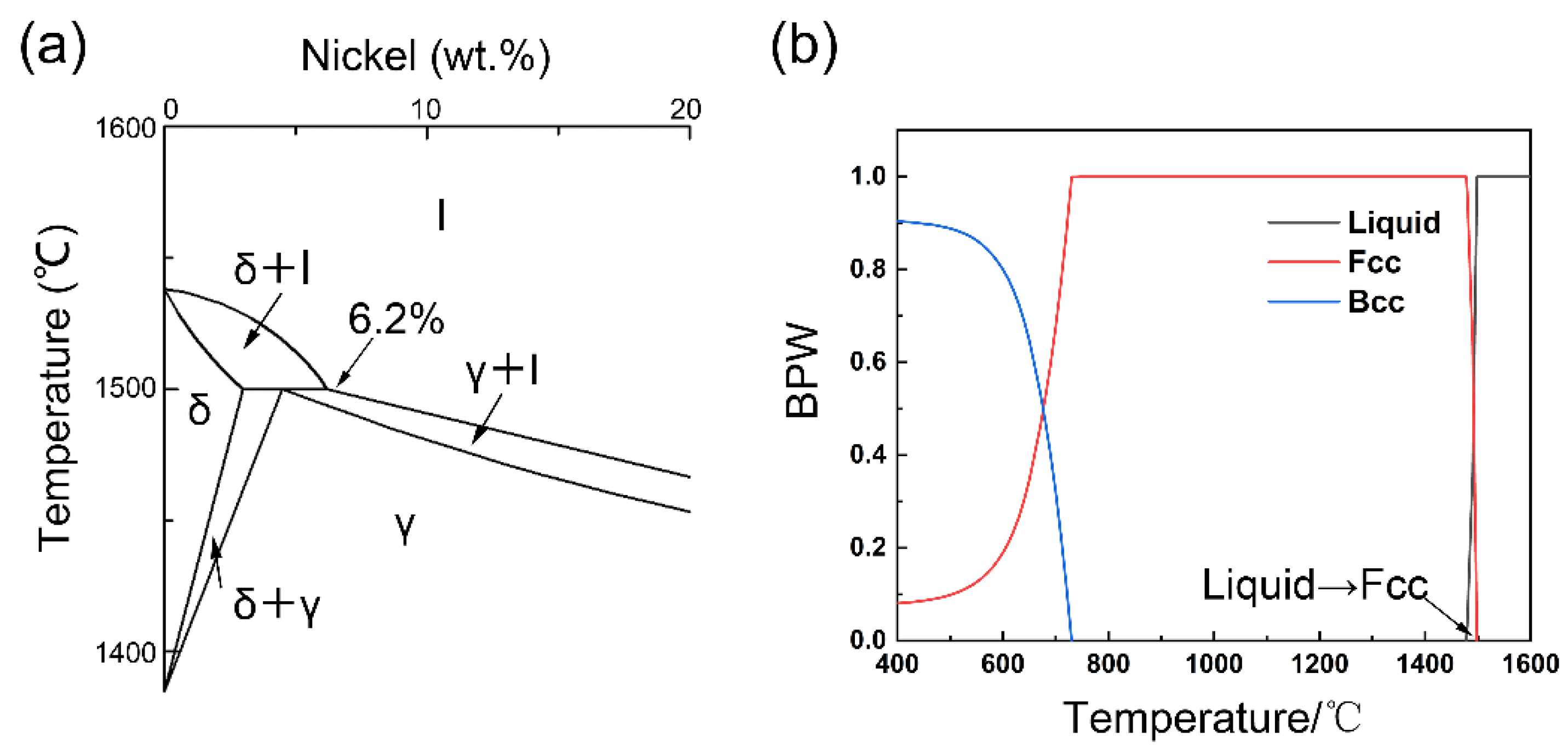
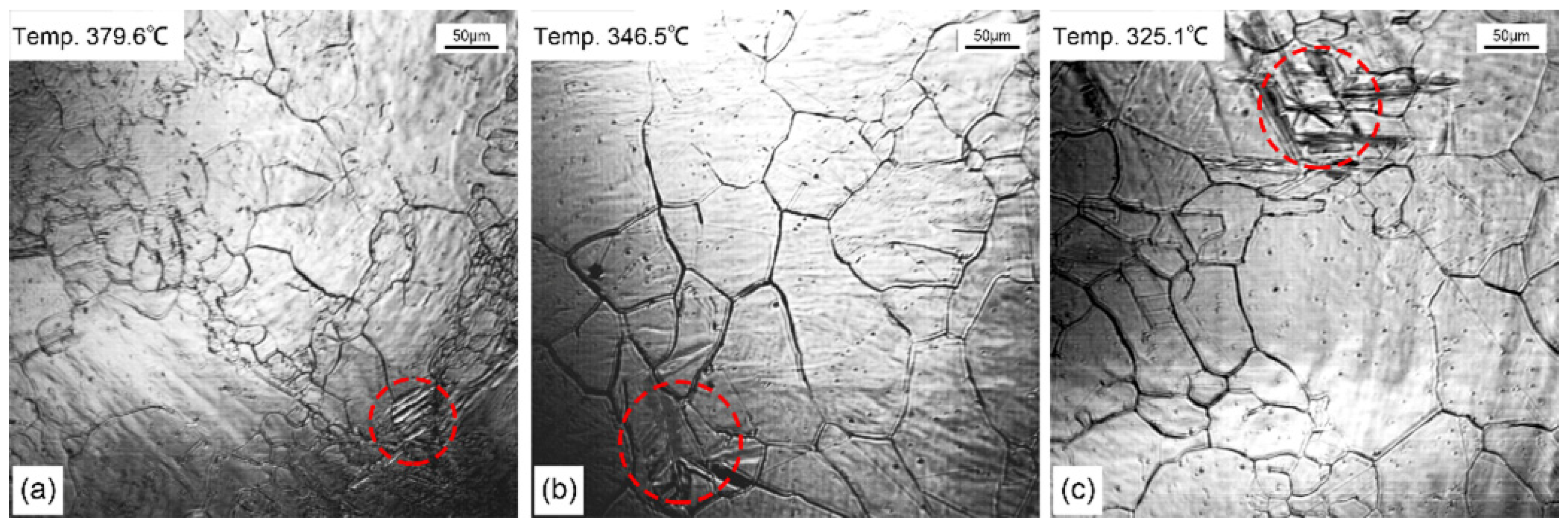
3.1. The Effect of Ni on the Microstructure Evolution

The microstructure of the deposited metals with different Ni contents are shown in Figure 2. The interdendritic zone (IDZ) in the deposited metals can be clearly seen in Figure 2a–c. Combined with the micrographs etched using Lepera solution shown in Figure 2d–f, it can be seen that martensite or austenite existed in IDZ while bainite formed in the dendrite core zone (DCZ). TEM was employed to explore the microstructures in DCZ and IDZ. As shown in Figure 3, the microstructure in DCZ and IDZ consists of a lath microstructure, and this indicates that the microstructure in IDZ is mainly martensite. Moreover, the lath of martensite in IDZ is obviously finer than that of bainite in DCZ, as shown in Figure 3b. This is consistent with previous research [20]. Perhaps due to the fact that the transformation temperature of martensite is lower than that of bainite and that the lath of martensite is finer than that of bainite.
As shown in Figure 4, the element distribution in the deposited metal of Ni7.5 revealed by EPMA, it is clear Ni and Mn that are segregated in IDC. The transformation temperature of austenite decreased with the increasing Ni and Mn content [21]. As a result, different microstructures were formed in IDZ and DCZ due to the different driving forces for the transformation of γ→α.
Figure 5 gives insight into the effect of Ni on the microstructure evolution of the deposited metals. There is a lot of CB in the deposited metals with different Ni contents. Moreover, most of the deposited metal consists of lath bainite and lath martensite.
Moreover, as depicted in Figure 6, statistical analysis of the area fraction of CB was made by the Image Pro Plus (IPP) in order to investigate the influence of CB on mechanical properties (ten SEM images were counted, and the maximum and minimum value were discarded). The results show that the area fraction of CB gradually increased from 6.9% to 8.3% and 11.4% with the increase of Ni content.
Through the above microstructure characterization, Ni has a significant influence on the transformation products of austenite. The most obvious feature is the presence of a large amount of CB in microstructure. Next, the discussion will focus on the formation mechanism of CB.
Ni equivalent has a significant effect on the solidification process, and the Ni equivalent could be estimated using Equation (1) [22]. The Ni equivalents of the Ni5.5, Ni6.5, and Ni7.5 deposited metals are 7.32 wt. %, 7.87 wt. %, and 9.25 wt. %, respectively. According to Fe–Ni binary phase diagram from Figure 7a, the solidification mode will change when the Ni equivalent exceeds 6.2% [7]. However, the Ni equivalent of the deposited metal with lowest Ni content exceeds 6.2%, so the liquid metal directly will solidify into γ without high-temperature ferrite (δ). Moreover, the solidification mode of the deposited metal has been verified by the Thermo-Calc simulation calculation (Figure 7b). This solidification process leads to the formation of coarse austenite grains.
N i e q = N i ( w t . % ) + 30 C + 30 N + 0.5 M n + 0.3 C u
Additionally, an in situ high temperature LCSM was adopted to detect the transformation temperature of bainite. It can be seen that the transformation temperature of bainite decreases from 379.6 °C to 346.5 °C and 325.1 °C with the increase of Ni content from 5.5% to 6.5% and 7.5% through Figure 8a–c. Moreover, the lower Bs means a greater driving force for transformation. This indicates that Ni has a significant influence on the formation of CB in the deposited metals.
According to early research [12], there are two necessary conditions required for the formation of CB: (a) adequate space for the growth of bainite ferrite laths; (b) sufficient driving force for the coalescence of bainite ferrite laths. With the increase of Ni content, the solidification mode changed, which resulted in the formation of coarse austenite and provided enough space for the growth of bainite ferrite laths. With the increase of Ni content, transformation temperature gradually decreased and the driving force for transformation increased, which provided adequate the driving force for the coalescence of bainite ferrite laths [12]. Therefore, there is a large amount of CB in the deposited metal with high Ni content.
Moreover, the formation mechanism of CB can not only be explained by adequate growth space and driving force, but it can also be further explained in terms of crystallographic characteristics. Junhak Pak has reported that the parallel bainite ferrite laths in adjacent regions will coalesce under external stress [13]. Anything that promotes the bainite ferrite laths in the close crystallographic orientation will stimulate the formation of CB. Compared to the deposited metals’ microstructure, the grain in the base metal is not as large as those in the deposited metals, so the close crystallographic orientation of the bainite ferrite laths is more crucial than adequate growth space for coalescence. Fundamentally, the crystallographic characteristics of microstructure depend on the differences in growth behavior of the bainite ferrite laths. During the growth of the bainite ferrite laths, the bainite ferrite laths nucleated and first grew at the grain boundaries of the prior austenite grain boundary (γ/γ interface),and the bainite ferrite laths could then also grow at the interface of the existing bainite ferrite laths and austenite (α/γ interface). This method of nucleation is called autocatalytic nucleation [23,24,25]. Autocatalytic nucleation has a significant influence on the crystallographic characteristics of microstructure. The crystallographic characteristics of microstructure were then characterized by EBSD.
Figure 9 shows inverse pole figures (IPF) and schematic diagrams of the nucleation method of the specimens with different Ni contents. From Figure 9a–c, it can be seen that there are two nucleation methods in the deposited metals (bainite ferrite laths nucleated at γ/γ and γ/α). The nucleation method of the bainite ferrite laths, called autocatalytic nucleation, nucleates at γ/α, marked by red dotted circle in Figure 9a,b. The schematic diagrams of the nucleation method were displayed in Figure 9d,e. Moreover, most of the bainite ferrite laths nucleated and grew at the prior austenite grain boundary (γ/γ). Bainite ferrite laths nucleated and grew at the side of the existingbainite ferrite laths and only in the local zone. It can be clearly seen that the orientation of the bainite ferrite laths is more complicated at the area where autocatalytic nucleation occurs.Moreover, autocatalytic nucleation weakens with the increase of Ni content, and those bainite ferrite laths with the close orientation will coalesce, promoted by the large driving force of bainite transformation. The mechanism of autocatalytic nucleation is still controversial, and it is generally believed to be related to the bainite transformation temperature [26,27,28].
XRD was adopted to investigate the RA content in the deposited metals. As depicted in Figure 10, it was found that the RA content changes from 1.5%, 5.7%, and 5.4% as the Ni content increases from 5.5%, 6.5%, and 7.5%, respectively. During the composition design of the deposited metal, the content of C was controlled at a very low level (0.05% in wt.) in order to improve the toughness and control the tendency of the deposited metals to cold crack. The transformation temperature gradually decreased with the increase of Ni content. When the Ni content exceeds 6.5%, the lower transformation temperature means that more C is needed to stabilize the austenite. However, there was not enough C in the deposited metal to stabilize the austenite, and the RA content did not continue to increase. However, the size and distribution of RA in deposited metals needs to be further studied by TEM.
TEM was employed to explore the formation mechanism of CB and the features of RA in the deposited metals with different Ni contents. As displayed in Figure 11a–c, it can be clearly seen that the bainite ferrite laths coalesced during the growth process, indicated by the red circles. In addition, the size of the CB is much larger than the surrounding bainite ferrite laths, resulting in a very uneven microstructure. Moreover, as displayed in Figure 11d–g, there are obvious RA films in the Ni6.5 and Ni7.5 deposited metals, which mainly exist between the film-like bainite ferrite laths.

3.2. The Effect of Ni on the Toughness of Deposited Metal

The impact energy of the deposited metals at different temperatures was shown in Figure 12. With the increase of Ni content, the impact energy of the deposited metals first increases and then decreases at different testing temperatures. Under the impact testing temperatures of RT, −20 °C, and −60 °C, the Ni6.5 deposited metal had the highest impact energy of 84.3 J (±3.7 J), 59.8 J (±2.3 J), and 36.0 J (±6.6 J), respectively. As the test temperature decreases, the toughness of the deposited metal deteriorates due to the ductile–brittle transition of the body-centered cubic (bcc) structure.
As shown in Figure 12, the impact energy of the deposited metals does not change monotonously with the increase of Ni content. This is because various factors (CB, RA) affect the toughness of the deposited metals. Careful analysis was then completed for the change in impact energy.
As depicted in Figure 13a, the size of CB is much larger than the surrounding bainite ferrite, resulting in an uneven microstructure. As displayed in Figure 13b, the crystal orientation of CB is almost consistent. The misorientation between the matrix and CB and the misorientation inside CB were then analyzed, as marked by black line in Figure 13c. As shown in Figure 13d, it can be seen that the interface between the matrix and CB is a high angle grain boundary, while the misorientation inside CB can be ignored. It is well known that only a high angle grain boundary can effectively hinder crack propagation [29,30]. As such, it can be surmised that the hindrance of the area inside the CB to crack propagation is almost ignored. Moreover, this conclusion can also be verified through the propagation path of the second cracks in impact fracture specimens in the next section (Figure 15).
Moreover, it is widely believed that the film-like RA between the bainite ferrite laths will have a positive effect on the toughness of the deposited metals [31]. When the RA film is encounters a crack during the propagation process, the crack tip will be blunted. When the Ni content increases from 5.5% to 6.5%, the content of CB in the deposited metals increases. However, the impact energy of the deposited metals still increases. This indicates that the formation of film-like RA between the bainite ferrite laths has a relatively stronger positive effect on the toughness as the Ni content increasing to 6.5%. Furthermore, the positive effect of film-like RA on toughness is greater than the negative effect of CB. When the Ni content continues to increase from 6.5% to 7.5%, the CB content also continues to increase. However, according to the XRD result, it is quantitatively calculated that the content of RA does not increase. As a result, the impact energy of the deposited metals is reduced.

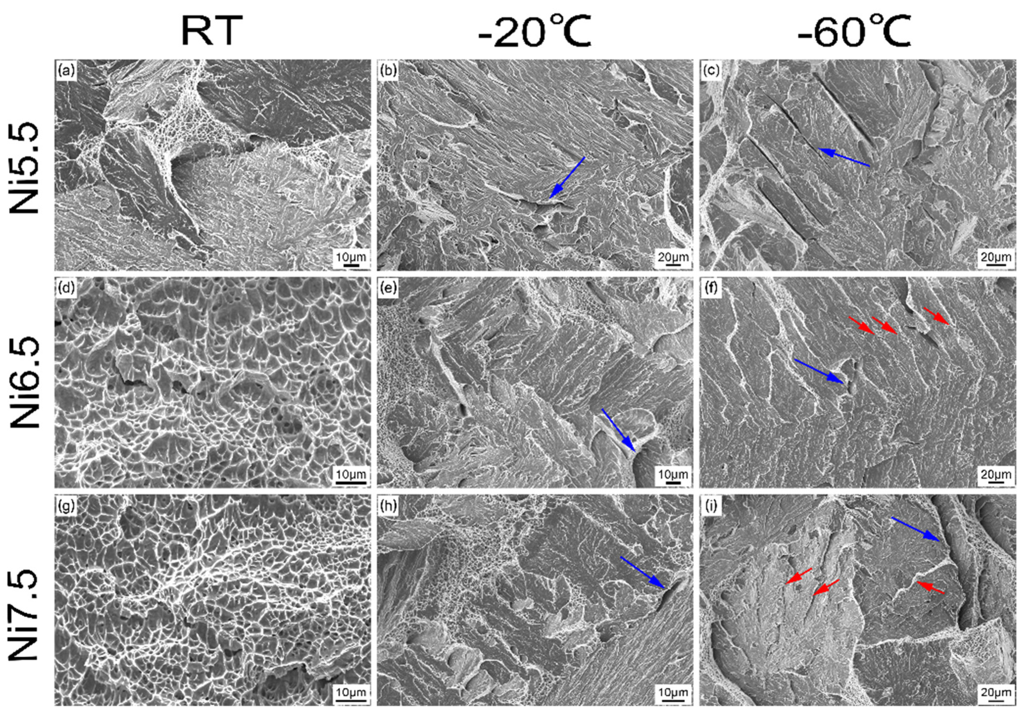
3.3. The Fracture Mechanism of Different Deposited Metals

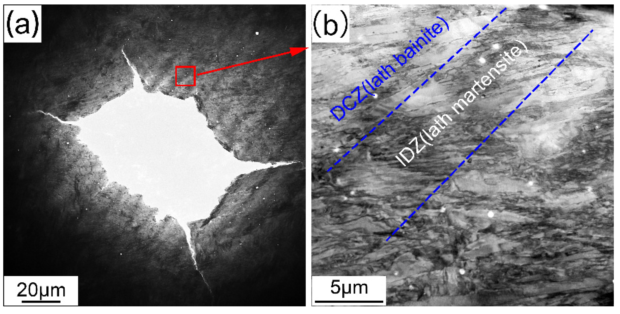
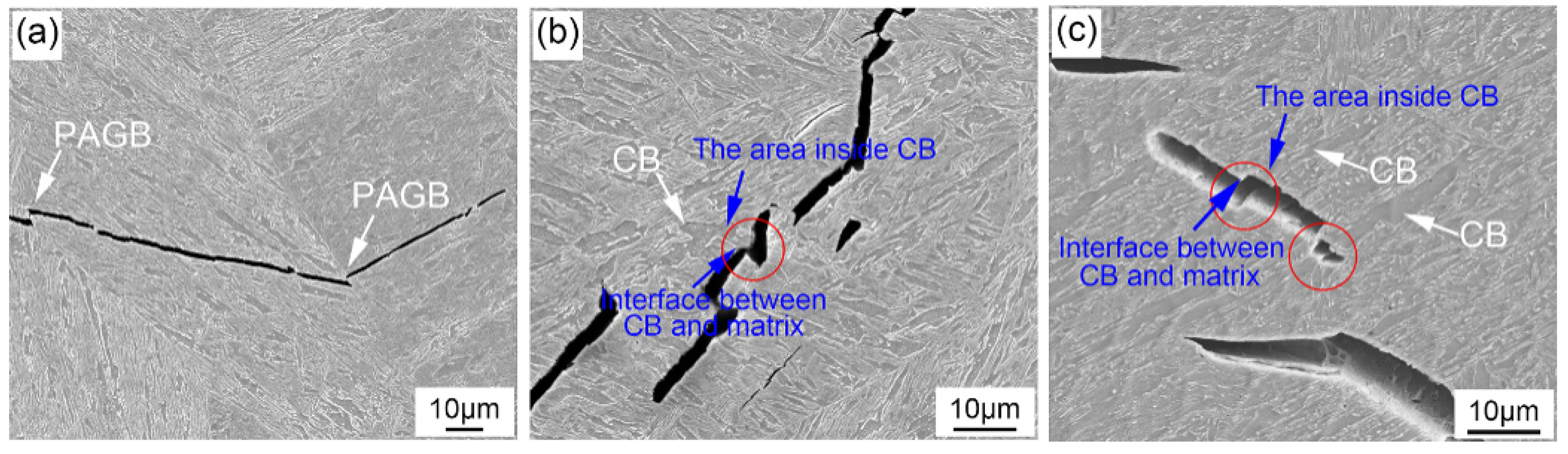
3.3.1. The Analysis of Crack Propagation Feature from the Perspective of Microstructure

In order to further explore the fracture mechanism of impact specimens, the fracture morphology of impact specimens were displayed in Figure 14. The specimens that impact the energy value that was the closest to the average value were adopted for fracture morphology observation.
As shown in Figure 14, due to the ductile–brittle transition in bcc structure metals, the fracture mode of all deposited metals will change from the microporous aggregation type to the transgranular cleavage type as the temperature decreases. Moreover, under the same test temperature conditions, due to the differences in the content of the retained austenite in the deposited metal with different Ni contents, the microstructure of the deposited metal has different resistances to the propagation of cracks. The zone of ductile fracture in Ni5.5 are relatively small compared to Ni6.5 and Ni7.5. At RT, a large number of river patterns appear on the impact fracture surface of the Ni5.5 specimen while the impact fracture surface of Ni6.5 and Ni7.5 specimens are composed of a large number of dimples. The fracture mode of Ni5.5 is a transgranular cleavage fracture, and the fracture mode of Ni6.5 and Ni7.5 is a microporous aggregation fracture. When the experimental temperature drops to −20 °C and −60 °C, the impact fracture mode of the deposited metals with different Ni contents are all transgranular cleavage fractures. Moreover, the cleavage planes in the Ni6.5 and Ni7.5 specimens are separated by dimples, and compared toNi5.5 specimen, the dimples are marked by red arrow. In addition, under the testing conditions of −20 °C and −60 °C, there are many second cracks in specimens with different Ni contents, marked by blue arrows in Figure 14. In order to further explore the fracture mechanism, the propagation path of the second cracks was investigated.
The propagation features of the second cracks in the specimens with different Ni contents are shown in Figure 15. The impact specimens fractured at −60 °C were adopted. As depicted in Figure 15a–c, in the Ni5.5 specimen, the crack is mainly deflected at the prior austenite grain boundary, while the second crack in Ni6.5 and Ni7.5 is discontinuous. This indicates that the ability to crack propagation of Ni5.5 is weak compared to Ni6.5 and Ni7.5. Meanwhile, in the process of crack propagation, there was an obvious phenomenon of passing through CB, marked by red cycles as shown in Figure 15b,c. As discussed above, the interface between CB and the matrix is a high angle grain boundary, while the interface inside CB is LAGB. Therefore, it can be seen from Figure 15b,c that the crack propagation direction is deflected at the interface between the CB and matrix, but it does not deflect inside the CB. Moreover, the misorientation inside CB is close to 0°, as shown in Figure 13c.

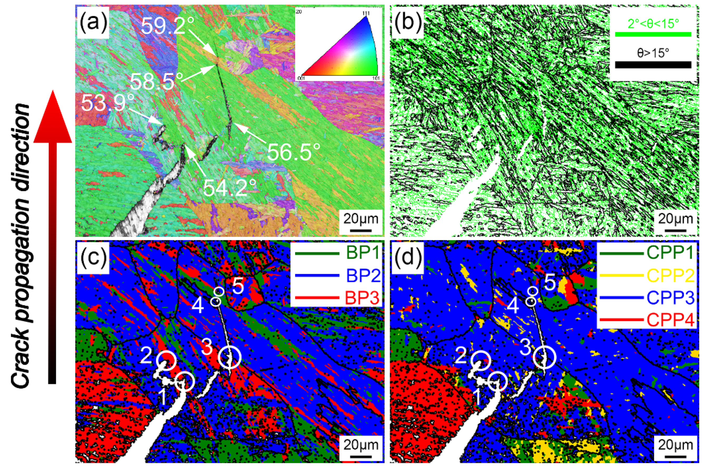
3.3.2. The Analysis of Crack Propagation Features from the Perspective of Crystallographic Characteristics

At present, the control unit of toughness in high strength structure materials is controversial [32,33], and the EBSD was used to further explore the propagation mechanism of the second crack. A second crack in Ni7.5 generated during the fracture process of the impact specimen at −60 °C was adopted for analysis as shown in Figure 16.
Bainite has a typical hierarchical structure similar to martensite. However, it is difficult to directly distinguish what substructure can effectively hinder crack propagation through IPF and the misorientation of grain boundary maps. Therefore, ARPGE software was used to analyze the bain packet (BP) and close-packed plane packets (CPP) in the microstructure [18]. According to the early research, the CPP group is always called the morphological packet while the Bain group is always called the crystallographic packet [34]. CPP is always used to describe the variants that share a common {110}α plane, which is parallel to one {111}γ plane. The BP is always adopted to describe the variants that are linked by low misorientation. From the perspective of crystallographic characteristics, CB can also be regarded as a special BP, while the misorientation inside it closes at 0°.
Moreover, the size of CPP is greater than the BP in 800 MPa grade low carbon bainite deposited metal due to the variant selection tendency shown in Figure 16c,d. Moreover, five places where crack propagation was impeded were marked by white circles and named as 1, 2, 3, 4 and 5 in Figure 16c,d. It can easily be seen that the crack propagation direction is always deflected or terminated at different BP interfaces. As shown in Table 3, the misorientation of the five typical interfaces that hinder crack propagation are depicted. It is obvious that all the misorientations (54.2°, 53.9°, 56.5, 58.5° and 59.2°) of the interface that impede the crack propagation belongs to a high angle grain boundary.
Furthermore, it can be seen that the propagation of cracks has a more direct relationship with BP than CPP in 800 MPa grade low carbon bainite deposited metal. This is consistent with previous research that indicated that the interface of Bain packets could impede crack propagation [35]. BP is the smallest control unit of toughness in 800 MPa grade low carbon bainite deposited metals.

4. Conclusions

In this study, the combined effects of CB and RA on the toughness of 800 MPa grade low carbon bainite deposited metals for marine applications with different Ni contents has been systematically investigated. The following conclusions were drawn from this study.
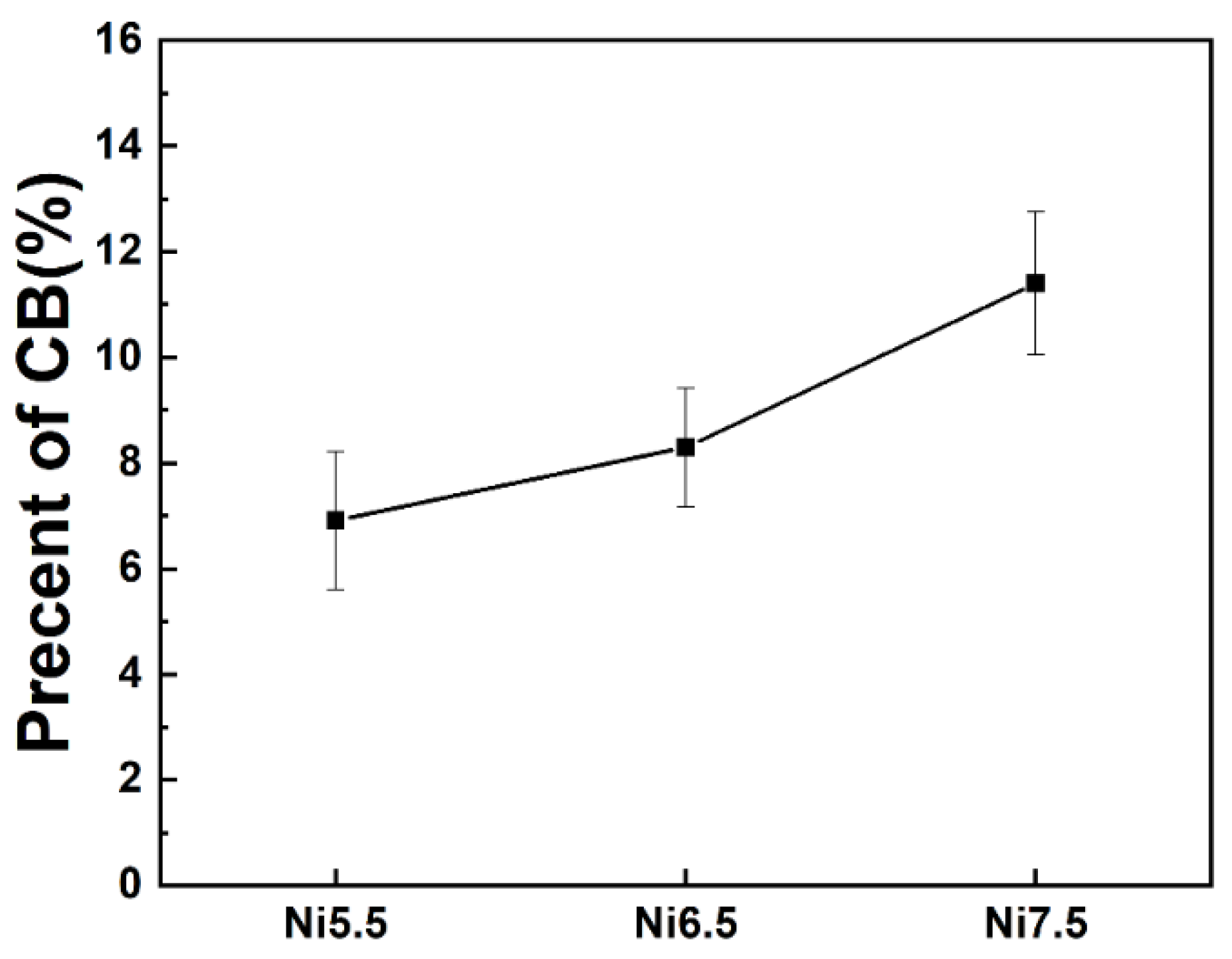
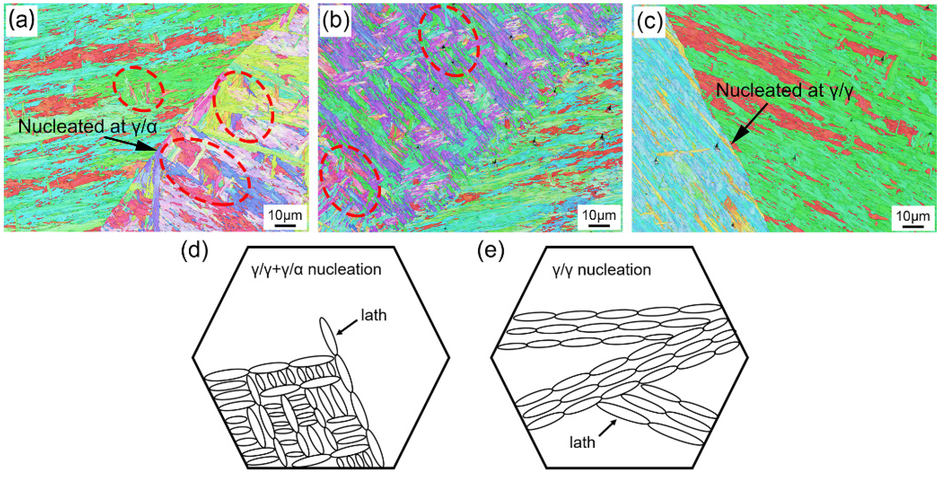
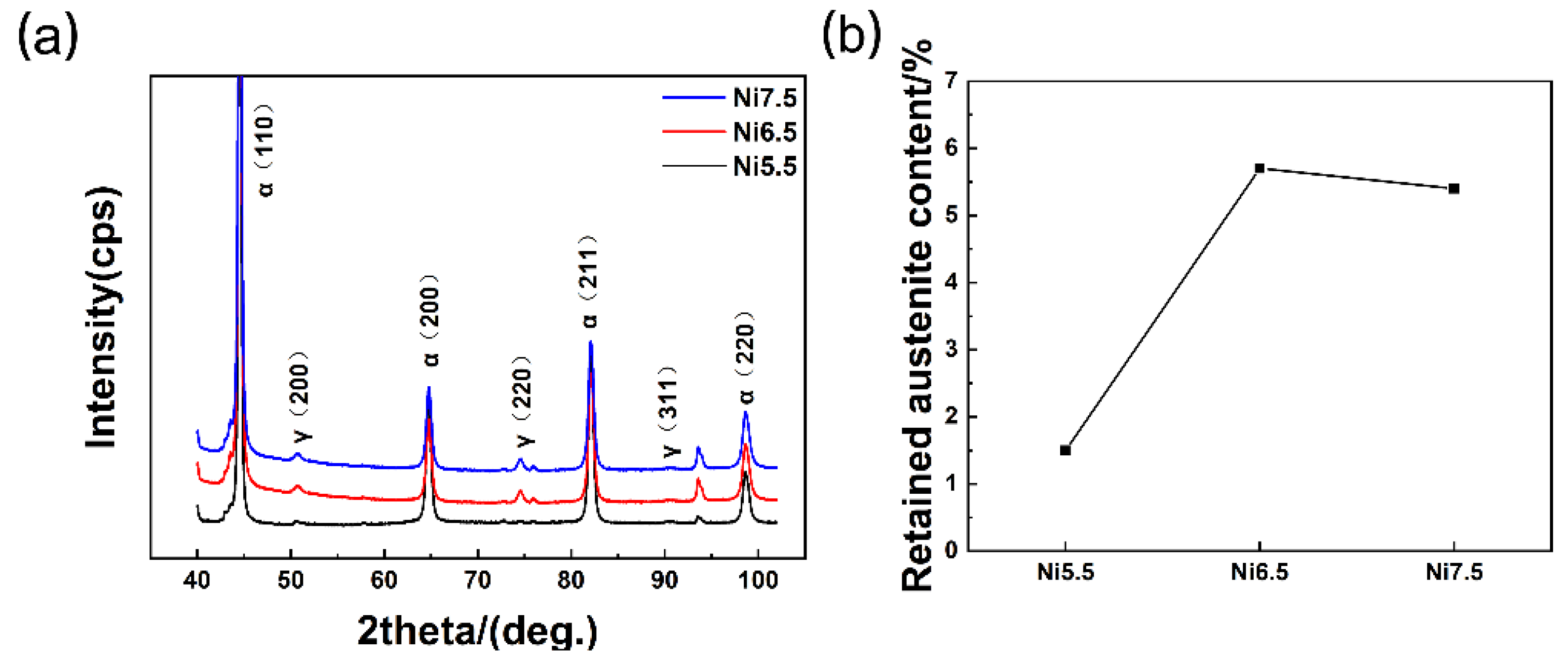
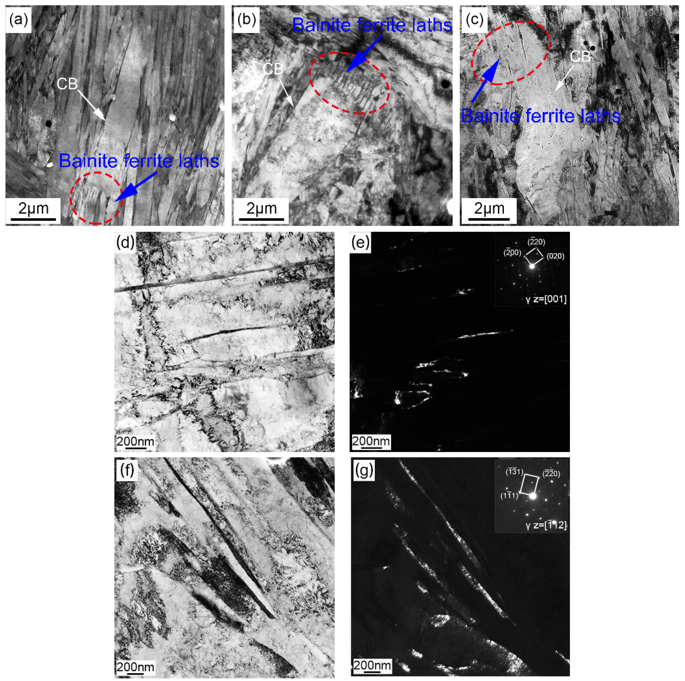
  • The formation of CB in 800 MPa grade low carbon bainite deposited metal mainly depended on the nucleation methods of bainite ferrite laths. Autocatalytic nucleation weakens with the increase of Ni content, and those bainite ferrite laths with close orientation will coalesce when promoted by the large driving force of bainite transformation. The fraction of CB increased from 6.9% to 8.3% and 11.4% with the increase of Ni content, while the content of RA did not continue to increase once the Ni content exceeded 6.5% due to the C in deposited metal being controlled at a very low level.
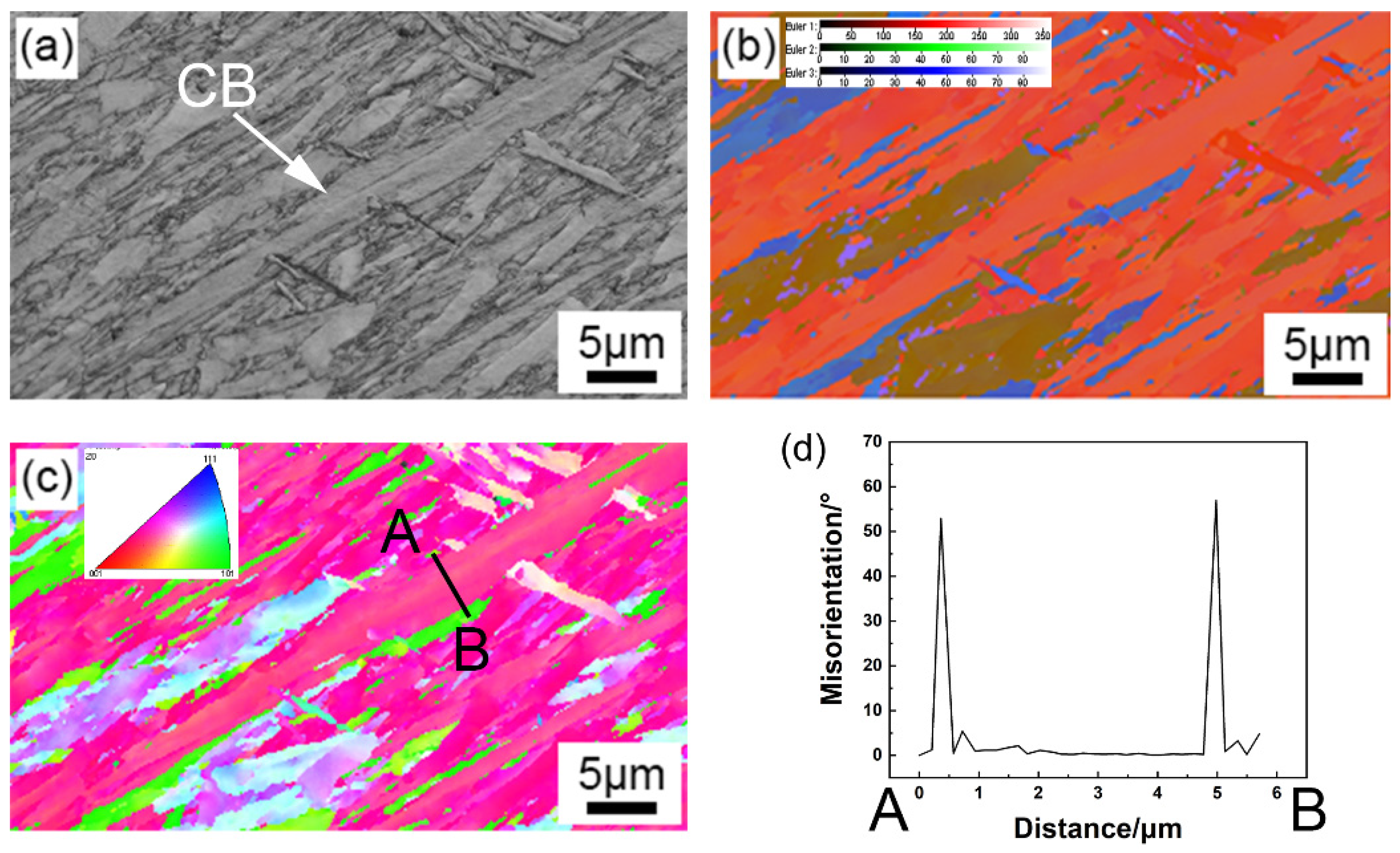
  • From the perspective of the crystallography characteristics, BP was the smallest control unit for toughness in 800 MPa grade low carbon bainite deposited metals.
  • With the increase of Ni content, the impact energy of deposited metal first increased and then decreased, mainly due to the comprehensive influence of CB and RA. With the increase of Ni content, the fraction of CB continued to increase, but the content of RA stabilized at 5.4% when the Ni content exceeded 6.5%. RA in deposited metal could improve the toughness, while the CB would deteriorate the toughness of deposited metal.
  • In low carbon bainite deposited metal, the toughness could be effectively improved effectively by increasing the content of RA while suppressing the formation of CB. This work provided the reference for the chemical composition design of 800 MPa grade steel welding consumables.

Author Contributions

Conceptualization, J.L., S.W., and S.L.; methodology, J.L., S.W., and S.L.; software, J.L. and J.S.; validation, J.L.; investigation, J.L.; resources, S.L.; data curation, J.L.; writing—original draft preparation, J.L.; writing—review and editing, J.L., J.S., and S.L.; visualization, J.L., J.S., and S.L.; supervision, S.W. and S.L.; project administration, S.L.; funding acquisition, S.L. All authors have read and agreed to the published version of the manuscript.

Funding

This work was funded by the major R&D Project of Liaoning Province (2020JH1/10100001), the National Science Foundation of Liaoning Province (2019JH3/30100039), and the Innovation Project of the Shenyang National Laboratory for materials science (SYNL-2020).

Conflicts of Interest

The authors declare no conflict of interest.

References

  1. Barrick, E.J.; DuPont, J.N. Microstructural characterization and toughness evaluation of 10 wt% Ni steel weld metal gas tungsten arc and gas metal arc weld fusion zones. Mater. Sci. Eng. A 2020, 796, 140043. [Google Scholar] [CrossRef]
  2. Lan, H.F.; Du, L.X.; Misra, R.D.K. Effect of microstructural constituents on strength–toughness combination in a low carbon bainitic steel. Mater. Sci. Eng. A 2014, 611, 194–200. [Google Scholar] [CrossRef]
  3. Tian, Y.; Zhou, J.; Shen, Y.; Qu, Z.; Xue, W.; Wang, Z. Improved Toughness of a High-Strength Low-Alloy Steel for Arctic Ship by Ni and Mo Addition. Adv. Eng. Mater. 2020, 22. [Google Scholar] [CrossRef]
  4. Gaojun, M.; Rui, C.; Cyril, C.; Roland, L.; Xili, G.; Yong, J.; Jianhong, C. Microstructural evolution and mechanical property development with nickel addition in low-carbon weld butt joints. J. Mater. Process. Technol. 2018, 262, 638–649. [Google Scholar]
  5. Sun, J.; Wei, S.; Lu, S. Influence of vanadium content on the precipitation evolution and mechanical properties of high-strength Fe–Cr–Ni–Mo weld metal. Mater. Sci. Eng. A 2019, 138739. [Google Scholar] [CrossRef]
  6. Kwon, H.; Kim, C.H. FRACTURE-BEHAVIOR IN MEDIUM-CARBON MARTENSITIC SI-STEEL AND NI-STEEL. Metall. Trans. a-Physical Metall. Mater. Sci. 1986, 17, 1173–1178. [Google Scholar] [CrossRef]
  7. Kang, B.Y.; Kim, H.J.; Hwang, S.K. Effect of Mn and Ni on the Variation of the Microstructure and Mechanical Properties of Low-carbon Weld Metals. ISIJ Int. 2000, 40, 1237–1245. [Google Scholar] [CrossRef] [Green Version]
  8. Keehan, E.; Karlsson, L.; Andren, H.O. Influence of carbon, manganese and nickel on microstructure and properties of strong steel weld metals Part 1—Effect of nickel content. Sci. Technol. Weld. Join. 2006, 11, 1–8. [Google Scholar] [CrossRef]
  9. Khodir, S.; Shibayanagi, T.; Takahashi, M.; Abdel-Aleem, H.; Ikeuchi, K. Microstructural evolution and mechanical properties of high strength 3–9% Ni-steel alloys weld metals produced by electron beam welding. Mater. Des. 2014, 60, 391–400. [Google Scholar] [CrossRef]
  10. Gao, G.; Zhang, H.; Gui, X.; Luo, P.; Tan, Z.; Bai, B. Enhanced ductility and toughness in an ultrahigh-strength Mn–Si–Cr–C steel: The great potential of ultrafine filmy retained austenite. Acta Mater. 2014, 76, 425–433. [Google Scholar] [CrossRef]
  11. Cui, H.B.; Lu, Y.; Xie, G.M.; Luo, Z.A.; Wang, C.X.; Kabwe, F.B.; Liu, Z.G.; Tang, X. The study on martensite morphology in the stir zone and its influence to impact toughness during friction stir welding medium–Mn ultrahigh strength steel. Mater. Sci. Eng. A 2020, 798, 140102. [Google Scholar] [CrossRef]
  12. Chang, L.C.; Bhadeshia, H.K.D.H. Microstructure of lower bainite formed at large undercoolings below bainite start temperature. Met. Sci. J. 1996, 12, 233–236. [Google Scholar] [CrossRef]
  13. Pak, J.; Suh, D.W.; Bhadeshia, H.K.D.H. Promoting the coalescence of bainite platelets. Scr. Mater. 2012, 66, 951–953. [Google Scholar] [CrossRef] [Green Version]
  14. Keehan, E.; Karlsson, L.; Andrén, H.-O.; Bhadeshia, H.K.D.H. Influence of carbon, manganese and nickel on microstructure and properties of strong steel weld metals: Part 3—Increased strength resulting from carbon additions. Sci. Technol. Weld. Join. 2012, 11, 19–24. [Google Scholar] [CrossRef]
  15. Bhadeshia, H.; Keehan, E.; Karlsson, L.; Andren, H.O. Coalesced bainite. Trans. Indian Inst. Met. 2006, 59, 689–694. [Google Scholar]
  16. Keehan, E.; Karlsson, L.; Bhadeshia, H.K.D.H.; Thuvander, M. Electron backscattering diffraction study of coalesced bainite in high strength steel weld metals. Met. Sci. J. 2008, 24, 1183–1188. [Google Scholar] [CrossRef]
  17. Lepera, F.S. IMPROVED ETCHING TECHNIQUE TO EMPHASIZE MARTENSITE AND BAINITE IN HIGH-STRENGTH DUAL-PHASE STEEL. J. Met. 1980, 32, 38–39. [Google Scholar] [CrossRef]
  18. Cayron, C. GenOVa: A computer program to generate orientational variants. J. Appl. Crystallogr. 2007, 40, 1179–1182. [Google Scholar] [CrossRef] [Green Version]
  19. Cayron, C.; Artaud, B.; Briottet, L. Reconstruction of parent grains from EBSD data. Mater. Charact. 2006, 57, 386–401. [Google Scholar] [CrossRef]
  20. Sun, J.; Lu, S. Influence of inter-dendritic segregation on the precipitation behaviour and mechanical properties in a vanadium-containing Fe–Cr–Ni–Mo weld metal. Scr. Mater. 2020, 186, 174–179. [Google Scholar] [CrossRef]
  21. Steven, W.; Haynes, A.G. Temperature of formation of martensite and bainite in low-allot steel. JISI 1956, 183, 349–359. Available online: www.researchgate.net/publication/303156093 (accessed on 19 May 2021).
  22. Bannykh, O.A.; Blinov, V.M.; Kostina, M.V.; Blinov, E. V Nickel saving in a 0Kh17N12M2-type (AISI 316) steel due to nitrogen alloying. Russ. Metall. 2006, 2006, 372–378. [Google Scholar] [CrossRef]
  23. Ravi, A.M.; Sietsma, J.; Santofimia, M.J. Exploring bainite formation kinetics distinguishing grain-boundary and autocatalytic nucleation in high and low-Si steels. Acta Mater. 2016, 105, 155–164. [Google Scholar] [CrossRef] [Green Version]
  24. Ravi, A.M.; Sietsma, J.; Santofimia, M.J. Bainite formation kinetics in steels and the dynamic nature of the autocatalytic nucleation process. Scr. Mater. 2017, 140, 82–86. [Google Scholar] [CrossRef]
  25. Olson, G.B.; Cohen, M. A Perspective on Martensitic Nucleation. Annu. Rev. Mater. Sci. 1981, 11, 1–32. [Google Scholar] [CrossRef]
  26. Takayama, N.; Miyamoto, G.; Furuhara, T. Effects of transformation temperature on variant pairing of bainitic ferrite in low carbon steel. Acta Mater. 2012, 60, 2387–2396. [Google Scholar] [CrossRef]
  27. Lambert-Perlade, A.; Gourgues, A.F.; Pineau, A. Austenite to bainite phase transformation in the heat-affected zone of a high strength low alloy steel. Acta Mater. 2004, 52, 2337–2348. [Google Scholar] [CrossRef]
  28. Gong, W.; Tomota, Y.; Adachi, Y.; Paradowska, A.M.; Kelleher, J.F.; Zhang, S.Y. Effects of ausforming temperature on bainite transformation, microstructure and variant selection in nanobainite steel. Acta Mater. 2013, 61, 4142–4154. [Google Scholar] [CrossRef]
  29. Nakanishi, D.; Kawabata, T.; Aihara, S. Brittle crack propagation resistance inside grain and at high angle grain boundary in 3% Si-Fe alloy. Acta Mater. 2018, 144, 768–776. [Google Scholar] [CrossRef]
  30. Zhou, P.; Zhou, J.; Ye, Z.; Hong, X.; Huang, H.; Xu, W. Effect of grain size and misorientation angle on fatigue crack growth of nanocrystalline materials. Mater. Sci. Eng. A 2016, 663, 1–7. [Google Scholar] [CrossRef]
  31. Dai, Z.; Chen, H.; Ding, R.; Lu, Q.; Zhang, C.; Yang, Z.; van der Zwaag, S. Fundamentals and application of solid-state phase transformations for advanced high strength steels containing metastable retained austenite. Mater. Sci. Eng. R Rep. 2021, 143, 100590. [Google Scholar] [CrossRef]
  32. Luo, H.; Wang, X.; Liu, Z.; Yang, Z. Influence of refined hierarchical martensitic microstructures on yield strength and impact toughness of ultra-high strength stainless steel. J. Mater. Sci. Technol. 2020, 51, 130–136. [Google Scholar] [CrossRef]
  33. Wang, C.; Wang, M.; Shi, J.; Hui, W.; Dong, H. Effect of microstructural refinement on the toughness of low carbon martensitic steel. Scr. Mater. 2008, 58, 492–495. [Google Scholar] [CrossRef]
  34. Cayron, C. EBSD imaging of orientation relationships and variant groupings in different martensitic alloys and Widmanstätten iron meteorites. Mater. Charact. 2014, 94, 93–110. [Google Scholar] [CrossRef]
  35. Chabok, A.; van der Aa, E.; De Hosson, J.T.M.; Pei, Y.T. Mechanical behavior and failure mechanism of resistance spot welded DP1000 dual phase steel. Mater. Des. 2017, 124, 171–182. [Google Scholar] [CrossRef] [Green Version]
Figure 1. (a) is the schematic diagram of the welding joint, and (b) is the sampling position of the mechanical samples. The number of 1–12 in (b) represents the welding sequence.
Crystals 11 00709 g001
Figure 2. Optical micrographs of the column zone of the deposited metals etched by 4% nital: (a) Ni5.5, (b) Ni6.5, and (c) Ni7.5; Interdendritic zone (IDZ) indicated by white arrows; Optical micrographs of the column zone of the deposited metals revealed by Lepera etchant: (d) Ni5.5, (e) Ni6.5, and (f) Ni7.5.
Crystals 11 00709 g002
Figure 3. The microstructure in dendrite core zone (DCZ) and IDZ of Ni5.5 analyzed by TEM; (b) is the local magnification of (a).
Crystals 11 00709 g003
Figure 4. The elements distribution in the deposited metal of Ni7.5 revealed by EPMA. (a) microstructure of deposited metal; (b) distribution of nickel (Ni); (c) distribution of manganese (Mn).
Crystals 11 00709 g004
Figure 5. SEM images of the deposited metals: (ac) microstructure of the column zone of Ni5.5, Ni6.5, and Ni7.5, respectively; CB is the abbreviation for coalesced bainite; these SEM images were taken at 4000 times by the FEI Inspect F50.
Crystals 11 00709 g005
Figure 6. The area fraction of CB in the deposited metals.
Crystals 11 00709 g006
Figure 7. (a) The Fe–Ni binary phase diagram [7]; (b) the solidification process simulated by the Thermo-Calc.
Crystals 11 00709 g007
Figure 8. In situ observation images of bainite transformation in the deposited metals: (a) Ni5.5, (b) Ni6.5, and (c) Ni7.5; the red circle marks the area where the transformation begins.
Crystals 11 00709 g008
Figure 9. (ac) are IPF images of Ni5.5, Ni6.5, and Ni7.5, respectively, and the red circle represents the place where autocatalytic nucleation occurs; (d,e) are the schematic diagrams of the nucleation method in the deposited metals.
Crystals 11 00709 g009
Figure 10. (a) The result of XRD analysis of the deposited metals. (b) The content of RA in the deposited metals.
Crystals 11 00709 g010
Figure 11. TEM images of the deposited metals; (ac) CB in the deposited metals of Ni5.5, Ni6.5, and Ni7.5, respectively; (d,f) are bright field images of Ni6.5 and Ni7.5, respectively; (e,g) are dark field images of Ni6.5 and Ni7.5, respectively.
Crystals 11 00709 g011
Figure 12. Variation in the impact energy of the deposited metals as a function of Ni contents at RT, −20 °C, and −60 °C.
Crystals 11 00709 g012
Figure 13. EBSD maps of CB: (a) BC map, (b) Euler angle color map, (c) IPF map, (d) the misorientation from matrix to CB.
Crystals 11 00709 g013
Figure 14. SEM micrographs of the fractured impact specimens. (ac) are the fracture morphology of Ni5.5 at RT, −20 °C, and −60 °C, respectively; (df) are the fracture morphology of Ni6.5 at RT, −20 °C, and −60 °C, respectively; (gi) are the fracture morphology of Ni7.5 at RT, −20 °C, and −60 °C, respectively; The blue arrow represents secondary cracks; the red arrow represents dimples between the cleave plane).
Crystals 11 00709 g014
Figure 15. The second crack propagation path images of impact fracture specimens at −60 °C; (a) Ni5.5, (b) Ni6.5, and (c) Ni7.5.
Crystals 11 00709 g015
Figure 16. The analysis of crystallographic characteristics of the second crack propagation path in Ni7.5. (a) IPF map; (b) misorientation of grain boundary map; (c) the Bain packet (BP) map; (d) The close-packed plane packets (CPP) map.
Crystals 11 00709 g016
Table 1. Chemical composition of A517GrQ and the deposited metals (wt. %).
MaterialsCSiMnCrNiMoVFe
A517GrQ0.150.211.040.772.090.48< 0.01Bal.
Ni5.5-deposited metal0.0450.391.030.995.450.710.053Bal.
Ni6.5-deposited metal0.0420.351.000.976.110.660.050Bal.
Ni7.5-deposited metal0.0440.361.001.017.430.700.054Bal.
Table 2. Welding parameters.
Welding ProcessShielding GasFlow Rate
(L/min)
Welding Current (A)Welding Voltage (V)Welding Speed (mm/min)Preheating
Temperature (°C)
Interpass
Temperature (°C)
GMAW95%Ar + 5% CO220230–25028–3030070–9080–110
Table 3. The misorientation and type of interface where crack propagation was impeded.
Misorientation (°)Interface Type
154.2BP3/BP2
253.9BP3/BP2
356.5BP3/BP2
458.5BP2/BP1
559.2BP1/BP2
Publisher’s Note: MDPI stays neutral with regard to jurisdictional claims in published maps and institutional affiliations.

