Article

Study on the Reliability of Sn–Bi Composite Solder Pastes with Thermosetting Epoxy under Thermal Cycling and Humidity Treatment

College of Materials Science and Technology, Nanjing University of Aeronautics and Astronautics, Nanjing 210016, China
*
Author to whom correspondence should be addressed.
Crystals 2021, 11(7), 733; https://doi.org/10.3390/cryst11070733
Submission received: 27 May 2021 / Revised: 18 June 2021 / Accepted: 22 June 2021 / Published: 24 June 2021
(This article belongs to the Special Issue Advances of Welding Materials)

Abstract

:
In this study, a Sn–Bi composite solder paste with thermosetting epoxy (TSEP Sn–Bi) was prepared by mixing Sn–Bi solder powder, flux, and epoxy system. The melting characteristics of the Sn–Bi solder alloy and the curing reaction of the epoxy system were measured by differential scanning calorimeter (DSC). A reflow profile was optimized based on the Sn–Bi reflow profile, and the Organic Solderability Preservative (OSP) Cu pad mounted 0603 chip resistor was chosen to reflow soldering and to prepare samples of the corresponding joint. The high temperature and humidity reliability of the solder joints at 85 °C/85% RH (Relative Humidity) for 1000 h and the thermal cycle reliability of the solder joints from −40 °C to 125 °C for 1000 cycles were investigated. Compared to the Sn–Bi solder joint, the TSEP Sn–Bi solder joints had increased reliability. The microstructure observation shows that the epoxy resin curing process did not affect the transformation of the microstructure. The shear force of the TSEP Sn–Bi solder joints after 1000 cycles of thermal cycling test was 1.23–1.35 times higher than the Sn–Bi solder joint and after 1000 h of temperature and humidity tests was 1.14–1.27 times higher than the Sn–Bi solder joint. The fracture analysis indicated that the cured cover layer could still have a mechanical reinforcement to the TSEP Sn–Bi solder joints after these reliability tests.

1. Introduction

Since the European Union’s Restriction of Hazardous Substances (RoHS) Directive was introduced in 2001, a great deal of research has been focused on lead-free solder alloys, owing to restrictions on the use of Sn–Pb solder [1,2,3,4]. With the miniaturization and complexity of electronic assembly and packaging, the use of Sn–Ag–Cu system solders were limited and low-temperature solder alloys are increasingly required in some electronic products [5,6]. The reflow profiles of low temperature solders and solder pastes have lower peak temperatures, which could reduce energy usage costs during production, and could also reduce the board warpage during reflow soldering [7,8]. Sn–Bi system solders are the mainly used in low temperature soldering processes, which are widely applied to solder thermosensitive devices (such as thermistors, light-emitting diodes, and the thermal systems in laptops) in the surface mounted technology (SMT) process [9,10]. Although the Sn–Bi solder alloy shows great economic efficiency in the electronic packaging, the solder joint has poor mechanical reliability due to the brittleness of Bi phase [11,12,13]. The resistance to thermal cycling and high temperature and humidity and mechanical shock are important properties to characterize the mechanical reliability of solder joints [14,15,16,17]. Various approaches have been attempted to increase the reliability of Sn–Bi solder joints, such as adding trace alloying elements or nanoparticles to Sn–Bi solders, which could inhibit the intermetallic compound (IMC) growth and increase the reliability. However, the melting temperature increased after alloying elements were added and the segregation of nanoparticles would also lead to crack defects [11,14,18,19,20,21,22]. Jung et al. [23,24,25,26] compared the mechanical properties and reliabilities of Sn–58Bi solder paste and Sn–58Bi solder paste with epoxy, which were provided by Tamura Corporation. The results showed that the shear strength of the Sn–58Bi epoxy solder joint was about two times higher than that of the Sn–58Bi solder joint, and the reliability of board level drop test was more than 10 times than that of Sn–Bi solder joint. The aging test found that epoxy resin could inhibit the growth rate of IMC, and the strength of solder joint was still higher than that of the Sn–Bi solder joint after a 1000 h aging test. However, there are few systematic investigations on the thermal cycling reliability and temperature and humidity reliability. Previous studies have investigated the wetting behavior and mechanical property of Sn–Bi solder paste strengthened by epoxy resin [12]. In this work, we focused on the mechanical properties of Sn–Bi and thermosetting epoxy (TSEP) composite Sn–Bi solder joints after thermal cycling test and temperature and humidity test. By comparing and analyzing the mechanical property evolution of Sn–Bi solder joints with different contents of epoxy resin, the best composition of TSEP Sn–Bi solder paste was determined.

2. Materials and Methods

2.1. Preparation of Solder Pastes

The thermosetting epoxy composite Sn–Bi solder paste (TSEP Sn–Bi) was prepared by Sn–Bi solder powder (particle size 25–45 μm), flux, and epoxy system. The Bi element content is 58 wt.%, and the epoxy system contains an appropriate proportion of thermosetting epoxy resin (E51, Nantong Xingchen Synthetic Material Company Limited, Nantong, China), curing agent Y, and accelerator Z (Guangzhou Shinshi Metallurgy and Chemical Company LTD, Guangzhou, China). In order to make the epoxy resin system suitable for the Sn–Bi solder reflow profile, epoxy resin, curing agent Y, and accelerator Z are mixed suitably by the ratio of 100:10:2. Three different proportions (3 wt.%, 5 wt.%, and 7 wt.%) of the epoxy system solution were added to solder paste, mixed, and stirred evenly to obtain resin-enhanced composite Sn–Bi solder pastes, and the eutectic Sn–Bi solder paste was selected for comparative analysis. The reinforced solder paste was recorded as TSEP Sn–Bi-x (x = 3, 5, 7).

2.2. DSC Measurement

The solidification heat absorption process of the Sn–Bi alloy and the epoxy system solidification heat release process were tested by differential scanning calorimeter (DSC). Discovery DSC Q2000 (TA Instruments, New Castle, DE, USA) was used, and the scan rate were set to ramp 10 °C/min from 25 °C to 200 °C and ramp 10 °C/min from 25 °C to 250 °C. DSC spectra were analyzed using the TA Universal Analysis software of TA Instruments.

2.3. Soldering

The FR-4 copper clad board (CCL), single sided with a thickness of 1.6 mm, was selected, and the surface treatment method of the copper plate was organic solderability preservatives (OSP). The 0603 (1.6 × 0.8 mm) chip resistor was chosen as the component and an optimized reflow profile was used to solder the TSEP Sn–Bi-x solder paste, which is shown in Figure 1. Figure 2a,b show the schematic diagrams of the solder joint before and after reflow soldering. Before soldering, the solder pastes were warmed up (25 °C) naturally for 2–4 h, and the solder paste mixer was used to thoroughly mix the powder and flux again. Solder pastes were printed to the printed circuit board (PCB) through a stencil. A manual printing and a manual components placement were used for soldering.

2.4. Temperature and Humidity Test (TH)

The temperature and humidity test of the solder joint was evaluated according to the JEDEC industrial standard JESD22-A101 “Steady State Temperature Humidity Bias Life Test”. The solder joints on the PCB were placed on fixtures to ensure temperature, and the humidity test conditions were set to 85 ± 2 °C/85 ± 2% RH (Relative Humidity), the aging time was 168 h, 500 h, and 1000 h.

2.5. Thermal Cycling Test (TC)

The thermal cycling test of the solder joint was evaluated to determine the solder interconnects’ ability, and to analyze the mechanical stresses induced by extremely alternating high and low temperatures. According to the JEDEC industrial standard JESD22-A104 “Temperature cycling”, a thermal cycling with a test condition from Ts(min) −40 °C to Ts(max) 125 °C was conducted for 200, 500, 750, and 1000 cycles. The time for each cycle was 70 min, in which the dwelling time at high and low temperature was 30 min each.

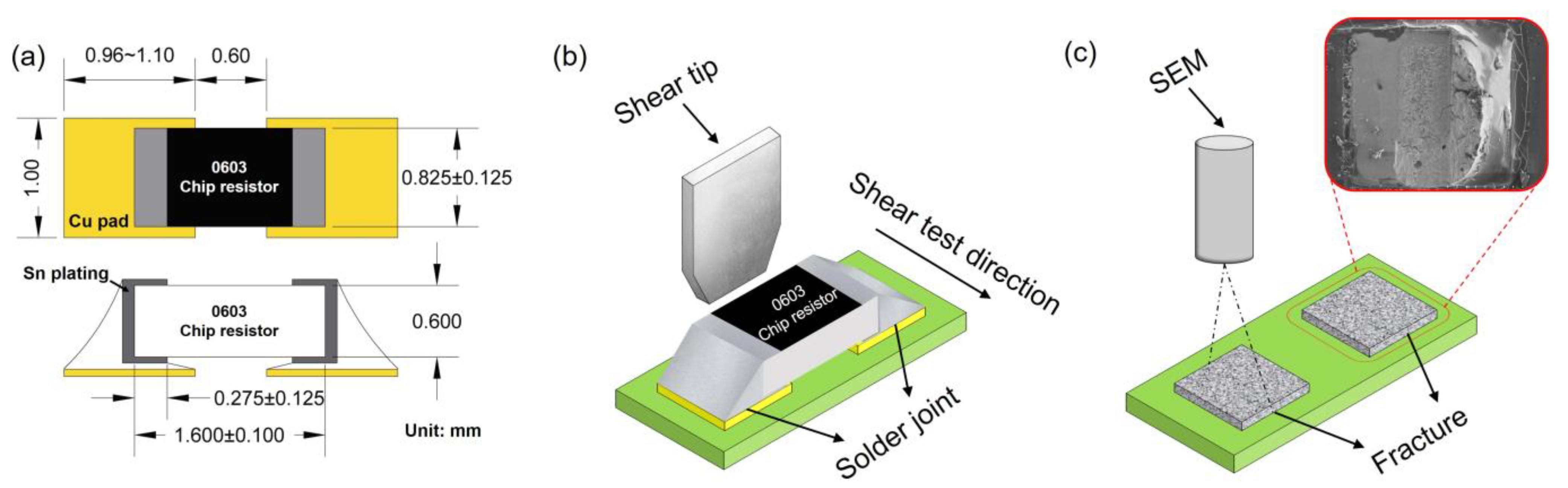
2.6. Shear Force Test

The mechanical property of solder joints was tested by FA1800 Failure Analysis tool (Eberts Electronics (S) Pte Ltd., Ang Mo Kio, Singapore), according to Japanese Industrial Standard JIS Z 3198-7 “Method for shear force of solder joints on chip components”. The height of shear tip from the surface of the PCB was 115 μm (less than or equal to one-fourth of the component thickness), and the test speed was set as 200 μm/s. Figure 3a shows the parameters of component and copper pad, and Figure 3b depicts the schematic of shear force test.

2.7. Microstructure Observation and Fracture Analysis

To observe the microstructure changes of the intermetallic compound formed at the interface between the solder and the Cu base metal, the samples were ground with #240, #600, #1200, #4000 silicon carbide grinding paper. After polishing, Cu and Sn were corroded with HCl and H2O2 aqueous solution and hydrochloric acid alcohol solution respectively. A Scanning Electron Microscope (SEM, Hitachi, S3400N TypeⅡ, Tokyo, Japan) and Energy Disperse Spectroscopy (EDS, Oxford instruments, Abingdon, Oxfordshire, UK) were used to analyze IMCs and microstructures.
Using SEM to observe and analyze the fracture morphology of solder joints after shear force test. Figure 3c shows the schematic of fracture micromorphology observation by SEM.

3. Results and Discussion
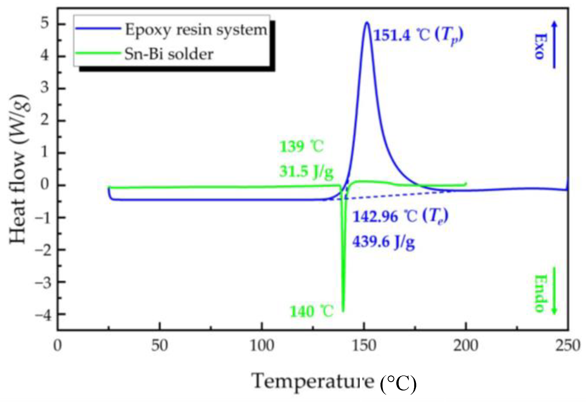
3.1. DSC Analysis

Figure 4 shows the DSC thermogram of the curing reaction of the epoxy resin system and the melting curve of Sn–Bi solder alloy. The intersection point of the tangent line between the baseline before the peak and the tangent line on the left side of the peak were used to characterize the Te extrapolated peak onset temperature, and the peak of the epoxy resin system curve was defined as the Tp peak maximum temperature. The curve showed that the exothermic curing reaction began slowly and reached a maximum reaction rate at the peak temperature (Tp) of 151.4 °C. Due to the lack of unreacted material (hydroxyl), the reaction slowed down. The extrapolated peak onset temperature (Te) was 142.96 °C, higher than the melting temperature of the Sn–Bi solder alloy (139 °C). The epoxy resin system started curing after the Sn–Bi solder alloy began melting, which could reduce the residue of flux and epoxy resin in the solder.

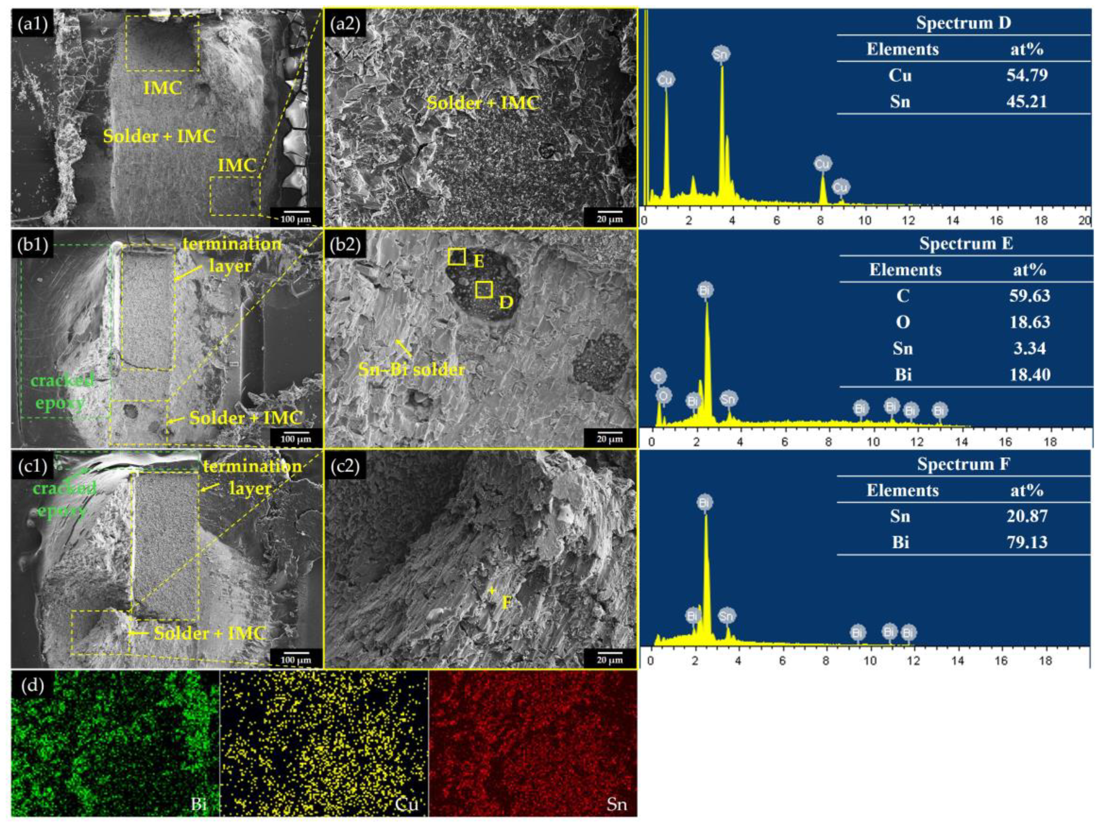
3.2. Microstructure Observation

Figure 5a shows the cross-sectional microstructure of the Sn–Bi solder joints and the TSEP Sn–Bi-x solder joints after soldering. There was a cured epoxy cover layer on the surface of the solder joint in Figure 5(a2–a4), different from Figure 5(a1). It can be observed that the greater the content of epoxy resin system added, the thicker the cured epoxy cover layer was. However, some pore defects were observed in the TSEPC Sn–Bi-7 solder joints. The epoxy resin was cured by the polymerization reaction, and the tiny bubbles in the epoxy resin system or the gaseous substances dissolved in the epoxy resin were heated and expanded during the reaction. The gas was no longer compatible with the epoxy system and would migrate and aggregate together to form a larger bubble. While the wetting and melting behavior pushed gas out, some bubbles could not be evacuated in time and remained in the solder joints to form pores.
As shown in Figure 5(b1–b4) and Figure 5(c1–c4) after 1000 h of TH and 1000 cycles of TC, the cured cover layer still existed, which provided protection for solder joints, no cracks were detected, and the epoxy resin curing process did not affect the transformation of the microstructure, which is shown in Figure 6.
The microstructure in Figure 6(a1–a4) shows that the convex bright phase was the Bi-phase, and the recessed dark phase was the Sn-phase after corrosion. The interface between the Sn–Bi alloy and the copper was a thin Cu6Sn5 intermetallic compound (IMC) layer. After 1000 h of the temperature and humidity test, both the Cu6Sn5 layer of the Sn–Bi solder joint and the TSEP Sn–Bi-x solder joint grew slowly, and the Cu3Sn layer was not observed. The diffusion of Sn and Bi atoms resulted in the Sn-phase, and the Bi-phase had obviously coarsened, as shown in Figure 6(b1–b4). However, after 1000 cycles of the thermal cycling test, the Sn and Bi were obviously diffused and coarsened as shown in Figure 6(c1–c4). The Arrhenius formula [3,27] represented that the higher temperature could provide a greater kinetic energy of atoms, increasing the diffusion coefficient exponentially. Therefore, compared to the aging temperature of 85 °C, the high temperature zone 125 °C of the temperature cycling test could increase the diffusion coefficient of Sn atoms and Bi atoms and promote the growth of crystal grains in the Sn-rich phase and the Bi-rich phase. The more Sn atoms were diffused to the IMC layer, the thicker the IMC layer became and the Bi-phase began to segregate near the interfacial layer [28,29].

3.3. Shear Force Test

Figure 7 shows the shear force of the Sn–Bi solder joint and the TSEP Sn–Bi-x (x = 3, 5, 7) solder joints after 1000 cycles of TC and 1000 h of TH. The shear force of the TSEP Sn–Bi-x (x = 3, 5, 7) solder joints was 1.42–1.55 times higher than the Sn–Bi solder joint after soldering. The greater the epoxy resin system content, the higher shear force it provided. After TC 1000 cycles and TH 1000 h, the shear force of the TSEP Sn–Bi solder joints was still higher than that of the Sn–Bi solder joint, which indicated that the addition of epoxy resin system could improve the reliability of Sn–Bi solder joints.
Figure 7a shows the shear force of 1000 cycles of the thermal cycling test. It was observed that with the increasing of cycles, the shear force of the Sn–Bi solder joint increased at first and then decreased after 500 cycles. However, the shear force of the TSEP Sn–Bi-3 and TSEP Sn–Bi-5 solder joints increased from the start and decreased after 250 cycles, and the shear force of the TSEP Sn–Bi-7 solder joint decreased all the time. Figure 7b shows the shear force of 1000 h of temperature and humidity test. With the increase in aging time, the shear force of the Sn–Bi and TSEP Sn–Bi-x (x = 3, 5) solder joints increased, and the shear forces of the TSEP Sn–Bi-7 decreased from 52.68 N to 47.20 N after 1000 h. The shear force of the TSEP Sn–Bi-x (x = 3, 5, 7) solder joints after 1000 cycles of the thermal cycling test is 1.23–1.35 times higher than the Sn–Bi solder joint, and after 1000 h of the temperature and humidity test, is 1.14–1.27 times higher than the Sn–Bi solder joint.

3.4. Fracture Morphology Analysis

In the previous study, the cured epoxy resin had a mechanical reinforcement effect, which could improve the shear strength of solder joints. Compared to other contents of the epoxy resin system, the content of 5 wt.% adding had the best wettability and could obtain a higher shear strength. Therefore, Sn–Bi and TSEP Sn–Bi-5 are selected for comparison to analyze the fracture morphology [12]. Figure 8 shows the fracture morphology of the Sn–Bi and TSEP Sn–Bi-5 solder joints. The epoxy resin system spread around the components with the flow of the flux during reflow soldering. Meanwhile, the viscosity increased as the rise in temperature and cross-linking reaction occurred. Compared to Figure 8(a1), there was an obviously cured cover layer on the TSEP Sn–Bi-5 solder joints as shown in Figure 8(a2). The cured epoxy around and on the bottom of the components would provide a mechanical resistance on the solder joints and improve the shear strength of the solder joints. At the same time, the cured epoxy can be used as an adhesive, which could strengthen the ability to fix the parts on the circuit board.
Although the epoxy resin has excellent longevity and resistance to aging, previous studies have shown that higher humidity and temperature reduced the mechanical properties of epoxy resin [30,31]. After 1000 h of the TH test and 1000 cycles of the TC test, the cured cover layer began to become brittle and cracked from the edge of solder joints, as shown in Figure 8(b2,c2), which means that the mechanical protection of the epoxy resin for the solder joint was reduced after aging. However, the cured cover layer could still enhance the solder joint, and obtained a higher shear strength compared to the Sn–Bi solder joint in Figure 8(b1,c1).
Figure 9 shows the SEM and EDS mapping analysis of Sn–Bi and TSEP Sn–Bi-5 solder joints. It is observed that there were many differences between the fracture morphologies of the Sn–Bi and TSEP Sn–Bi-5 solder joints. The Sn–Bi solder joint at TC 1000 cycles shows a brittle fracture, as exhibited in Figure 9(a1,a2), owing to the increase of Cu6Sn5 IMC thickness, the growth of grains, and the segregate of Bi atoms. The fracture forms included cleavage fracture and intergranular fracture. The cleavage fracture occurred inside the solder, mainly along the internal cracks of the Bi-rich crystal grains at the interface, and the fracture morphology principally presented cleavage steps and smooth crystal planes. The intergranular fracture occurred at the interface between Bi crystal grains and Cu6Sn5 crystal grains, which was attributed to the coarsening of the crystal grains after thermal aging. Fracture occurs preferentially along with the crystal, due to the bonding force reduced between the Cu6Sn5 crystal grains and the Sn and Bi crystal grain boundaries. Figure 9d shows the EDS mapping of Figure 9(a2) where it can be seen that high contents of Bi, Cu, and Sn were detected in the solder fracture surfaces, which means that the fracture path penetrated the interface layer and the enriched Bi-phase.
However, Figure 9(b1,b2) and Figure 9(c1,c2) show that the main fracture location of the TSEP Sn–Bi-5 solder joint was inside the solder. The fracture morphology was cleavage fracture, part of the IMC was exposed on the fracture surface, and the rest was the cracking of the plating layer of the components. The cured epoxy resin became brittle and cracked after TH 1000 h and TC 1000 cycles, which reduced the strengthening effect on the solder joints, but it could still have a mechanical reinforcement to the solder joint.
It can be observed from Figure 9(b1,c1) that cracked epoxy resin appeared on the surface of the solder joints. The epoxy resin was deformed and fractured when the solder joint was subjected to shear force, and exposure to the high temperature environment could accelerate aging and embrittlement process of the epoxy resin.

4. Conclusions

In this study, 3, 5, and 7 wt.% epoxy systems were mechanically mixed with Sn–Bi solder paste. The reliability of the Sn–Bi solder joint and the TSEP Sn–Bi-x (x = 3, 5, 7) solder joint in thermal cycling and temperature-humidity environment were investigated by a microstructure analysis, shear test, and fracture morphology analysis. The results indicated that:
1. The addition of the epoxy system could form a cured cover layer on the surface of the solder joint, and after TC 1000 cycles and TH 1000 h, the cured cover layer still existed but did not affect the microstructure evolution of the Sn–Bi.
2. Compared to the Sn–Bi solder joint, the TSEP Sn–Bi-x (x = 3, 5, 7) solder joint had better shear strength. The shear force of the TSEP Sn–Bi-x (x = 3, 5, 7) solder joints were 1.42–1.56 times higher than the Sn–Bi solder joint.
3. After 1000 cycles, a thermal cycling test, and a 1000 h temperature and humidity test, the shear force of the TSEP Sn–Bi-x (x = 3, 5, 7) solder joints were 1.23–1.35 times and 1.14–1.27 times higher than the Sn–Bi solder joint. Compared to the TSEP Sn–Bi-3 and TSEP Sn–Bi-7 solder joints, the TSEP Sn–Bi-5 solder joint has more stable and reliable performance.
4. The fracture morphology indicated that the cured epoxy resin still added a mechanical reinforcement to the solder joint, although it embrittled and cracked after TH 1000 h and TC 1000 cycles, which reduced the strengthening effect of the solder joins.

Author Contributions

Conceptualization, S.X.; methodology, L.L.; software, L.L.; validation, L.L.; formal analysis, L.L.; investigation, L.L., R.N., and P.Z.; resources, S.X.; data curation, L.L. and R.N.; writing—original draft preparation, L.L.; writing—review and editing, L.L., R.N., and P.Z.; visualization, L.L. and J.W.; supervision, S.X.; project administration, S.X.; funding acquisition, S.X. All authors have read and agreed to the published version of the manuscript.

Funding

This work was funded by the National Natural Science Foundation of China (Grant No.51975284) and the Priority Academic Program Development of Jiangsu Higher Education Institutions (PAPD).

Data Availability Statement

The data could be obtained from the corresponding author.

Acknowledgments

The authors sincerely acknowledge the financial supports by the National Natural Science Foundation of China, Grant No. 51975284, as well as the Priority Academic Program Development of Jiangsu Higher Education Institutions (PAPD).

Conflicts of Interest

The authors declare no conflict of interest.

References

  1. Chellvarajoo, S.; Abdullah, M.Z. Microstructure and mechanical properties of Pb-free Sn–3.0Ag–0.5Cu solder pastes added with NiO nanoparticles after reflow soldering process. Mater. Des. 2016, 90, 499–507. [Google Scholar] [CrossRef]
  2. Liu, Y.; Fu, H.; Sun, F.; Zhang, H.; Kong, X.; Xin, T. Microstructure and mechanical properties of as-reflowed Sn58Bi composite solder pastes. J. Mater. Process. Technol. 2016, 238, 290–296. [Google Scholar] [CrossRef]
  3. Yu, D.Q.; Zhao, J.; Wang, L. Improvement on the microstructure stability, mechanical and wetting properties of Sn–Ag–Cu lead-free solder with the addition of rare earth elements. J. Alloys Compd. 2004, 376, 170–175. [Google Scholar] [CrossRef]
  4. Zhang, L.; Long, W.-m.; Wang, F.-j. Microstructures, interface reaction, and properties of Sn–Ag–Cu and Sn–Ag–Cu–0.5CuZnAl solders on Fe substrate. J. Mater. Sci. Mater. Electron. 2020, 31, 6645–6653. [Google Scholar] [CrossRef]
  5. Wang, F.; Chen, H.; Huang, Y.; Liu, L.; Zhang, Z. Recent progress on the development of Sn–Bi based low-temperature Pb-free solders. J. Mater. Sci. Mater. Electron. 2019, 30, 3222–3243. [Google Scholar] [CrossRef]
  6. Liu, Y.; Tu, K.N. Low melting point solders based on Sn, Bi, and In elements. Mater. Today Adv. 2020, 8, 100115. [Google Scholar] [CrossRef]
  7. Wong, E.; Seah, S.; Selvanayagam, C.; Rajoo, R.; Van Driel, W.; Caers, J.; Zhao, X.; Owens, N.; Leoni, M.; Tan, L.; et al. High-Speed Cyclic Bend Tests and Board-Level Drop Tests for Evaluating the Robustness of Solder Joints in Printed Circuit Board Assemblies. J. Electron. Mater. 2009, 38, 884–895. [Google Scholar] [CrossRef]
  8. Liao, M.-C.; Huang, P.-S.; Lin, Y.-H.; Tsai, M.-Y.; Huang, C.-Y.; Huang, T.-C. Measurements of Thermally-Induced Curvatures and Warpages of Printed Circuit Board during a Solder Reflow Process Using Strain Gauges. Appl. Sci. 2017, 7, 739. [Google Scholar] [CrossRef]
  9. Öztürk, E.; Aksöz, S.; Keşlioğlu, K.; Maraşlı, N. The measurement of thermal conductivity variation with temperature for Sn-20wt.% In based lead-free ternary solders. Thermochim. Acta 2013, 554, 63–70. [Google Scholar] [CrossRef]
  10. Maruya, Y.; Hata, H.; Shohji, I.; Koyama, S. Bonding Characteristics of Sn-57Bi-1Ag Low-Temperature Lead-Free Solder to Gold-Plated Copper. Procedia Eng. 2017, 184, 223–230. [Google Scholar] [CrossRef]
  11. Kang, H.; Rajendran, S.H.; Jung, J.P. Low Melting Temperature Sn-Bi Solder: Effect of Alloying and Nanoparticle Addition on the Microstructural, Thermal, Interfacial Bonding, and Mechanical Characteristics. Metals 2021, 11, 364. [Google Scholar] [CrossRef]
  12. Liu, L.; Xue, S.; Liu, S. Mechanical Property of Sn-58Bi Solder Paste Strengthened by Resin. Appl. Sci. 2018, 8, 2024. [Google Scholar] [CrossRef] [Green Version]
  13. Shang, P.J.; Liu, Z.Q.; Li, D.X.; Shang, J.K. Bi-induced voids at the Cu3Sn/Cu interface in eutectic SnBi/Cu solder joints. Scr. Mater. 2008, 58, 409–412. [Google Scholar] [CrossRef]
  14. Park, B.G.; Myung, W.R.; Lee, C.J.; Jung, S.B. Mechanical, electrical, and thermal reliability of Sn-58 wt.%Bi solder joints with Ag-decorated MWCNT for LED package component during aging treatment. Compos. Part B Eng. 2020, 182, 107617. [Google Scholar] [CrossRef]
  15. Gu, J.; Lin, J.; Lei, Y.; Fu, H. Experimental analysis of Sn-3.0Ag-0.5Cu solder joint board-level drop/vibration impact failure models after thermal/isothermal cycling. Microelectron. Reliab. 2018, 80, 29–36. [Google Scholar] [CrossRef]
  16. Zang, L.; Yuan, Z.; Zhao, H.; Zhang, X. Wettability of molten Sn–Bi–Cu solder on Cu substrate. Mater. Lett. 2009, 63, 2067–2069. [Google Scholar] [CrossRef]
  17. Kim, K.S.; Matsuura, T.; Suganuma, K. Effects of Bi and Pb on oxidation in humidity for low-temperature lead-free solder systems. J. Electron. Mater. 2006, 35, 41–47. [Google Scholar] [CrossRef]
  18. Kotadia, H.R.; Howes, P.D.; Mannan, S.H. A review: On the development of low melting temperature Pb-free solders. Microelectron. Reliab. 2014, 54, 1253–1273. [Google Scholar] [CrossRef]
  19. Šebo, P.; Sr, P.Š.; Janičkovič, D.; Illeková, E.; Zemánková, M.; Plevachuk, Y.; Sidorov, V.; Švec, P. The influence of silver content on structure and properties of Sn–Bi–Ag solder and Cu/solder/Cu joints. Mater. Sci. Eng. A 2013, 571, 184–192. [Google Scholar] [CrossRef]
  20. Lee, C.J.; Min, K.D.; Park, H.J.; Jung, S.B. Mechanical properties of Sn-58 wt%Bi solder containing Ag-decorated MWCNT with thermal aging tests. J. Alloys Compd. 2020, 820, 153077. [Google Scholar] [CrossRef]
  21. Çadırlı, E.; Böyük, U.; Kaya, H.; Maraşlı, N. Determination of mechanical, electrical and thermal properties of the Sn-Bi-Zn ternary alloy. J. Non-Cryst. Solids 2011, 357, 2876–2881. [Google Scholar] [CrossRef]
  22. Cheng, S.; Huang, C.M.; Pecht, M. A review of lead-free solders for electronics applications. Microelectron. Reliab. 2017, 75, 77–95. [Google Scholar] [CrossRef]
  23. Myung, W.R.; Kim, Y.; Jung, S.B. Mechanical property of the epoxy-contained Sn–58Bi solder with OSP surface finish. J. Alloys Compd. 2014, 615, S411–S417. [Google Scholar] [CrossRef]
  24. Myung, W.R.; Kim, Y.; Jung, S.B. Evaluation of the Bondability of the Epoxy-Enhanced Sn-58Bi Solder with ENIG and ENEPIG Surface Finishes. J. Electron. Mater. 2015, 44, 4637–4645. [Google Scholar] [CrossRef]
  25. Myung, W.R.; Kim, Y.; Kim, K.Y.; Jung, S.B. Drop Reliability of Epoxy-contained Sn-58wt.%Bi Solder Joint with ENIG and ENEPIG Surface Finish Under Temperature and Humidity Test. J. Electron. Mater. 2016, 45, 3651–3658. [Google Scholar] [CrossRef]
  26. Kim, J.; Myung, W.R.; Jung, S.B. Effects of Aging Treatment on Mechanical Properties of Sn-58Bi Epoxy Solder on ENEPIG-Surface-Finished PCB. J. Electron. Mater. 2016, 45, 5895–5903. [Google Scholar] [CrossRef]
  27. Bao, N.; Hu, X.; Li, Y.; Jiang, X. Effects of thermal aging on growth behavior of interfacial intermetallic compound of dip soldered Sn/Cu joints. J. Mater. Sci. Mater. Electron. 2018, 29, 8863–8875. [Google Scholar] [CrossRef]
  28. Madeni, J.C.; Liu, S. Effect of thermal aging on the interfacial reactions of tin-based solder alloys and copper substrates and kinetics of formation and growth of intermetallic compounds. Soldagem Inspeção 2011, 16, 86–95. [Google Scholar] [CrossRef]
  29. Zhao, N.; Zhong, Y.; Huang, M.L.; Ma, H.T.; Dong, W. Growth kinetics of Cu6Sn5 intermetallic compound at liquid-solid interfaces in Cu/Sn/Cu interconnects under temperature gradient. Sci. Rep. 2015, 5, 13491. [Google Scholar] [CrossRef] [PubMed] [Green Version]
  30. Lettieri, M.; Frigione, M. Effects of humid environment on thermal and mechanical properties of a cold-curing structural epoxy adhesive. Constr. Build. Mater. 2012, 30, 753–760. [Google Scholar] [CrossRef]
  31. Alessi, S.; Conduruta, D.; Pitarresi, G.; Dispenza, C.; Spadaro, G. Accelerated ageing due to moisture absorption of thermally cured epoxy resin/polyethersulphone blends. Thermal, mechanical and morphological behaviour. Polym. Degrad. Stab. 2011, 96, 642–648. [Google Scholar] [CrossRef]
Figure 1. Reflow profile of solder paste.
Crystals 11 00733 g001
Figure 2. Solder joint of 0603 chip resistor schematic diagram: (a) Printing solder paste and placing component; (b) Solder joint after reflow soldering.
Crystals 11 00733 g002
Figure 3. Schematic of (a) Parameters of component and copper pad; (b) Shear force test; (c) Fracture micromorphology observation by SEM.
Crystals 11 00733 g003
Figure 4. DSC thermogram of the curing behavior of the epoxy resin system and the melting curve of the Sn–Bi solder.
Crystals 11 00733 g004
Figure 5. The Sn–Bi/Cu solder joints and TSEP Sn–Bi-x/Cu solder joints cross section after soldering: (a1a4) Solder joints after soldering; (b1b4) Solder joints after 1000 h; (c1c4) Solder joints after 1000 cycles.
Crystals 11 00733 g005
Figure 6. The microstructure of Sn–Bi/Cu solder joints and TSEP Sn–Bi-x/Cu solder joints: (a1a4) Solder joints after soldering; (b1b4) Solder joints after TH 1000 h; (c1c4) Solder joints after TC 1000 cycles.
Crystals 11 00733 g006
Figure 7. Shear force of Sn–Bi and TSEP Sn–Bi-x (x = 3, 5, 7): (a) Thermal cycling test; (b) Temperature and humidity test.
Crystals 11 00733 g007
Figure 8. Fracture morphology of Sn–Bi and TSEP Sn–Bi-5 solder joints: (a1,a2) Solder joints after soldering; (b1,b2) Solder joints after 1000 h; (c1,c2) Solder joints after 1000 cycles.
Crystals 11 00733 g008
Figure 9. SEM and EDS analysis of solder joints, (a1,a2) Sn–Bi solder joint after TC 1000 cycles; (b1,b2) TSEP Sn–Bi-5 solder joint after TC 1000 cycles and (c1,c2) TSEP Sn–Bi-5 solder joint after TH 1000 h; (d) EDS mapping of (a2).
Crystals 11 00733 g009
Publisher’s Note: MDPI stays neutral with regard to jurisdictional claims in published maps and institutional affiliations.

