Article

Taurine-Functionalized Carbon Nanotubes as Electrode Catalysts for Improvement in the Performance of Vanadium Redox Flow Battery

1
School of Resource and Environmental Engineering, Wuhan University of Science and Technology, Wuhan 430081, China
2
State Environmental Protection Key Laboratory of Mineral Metallurgical Resources Utilization and Pollution Control, Wuhan University of Science and Technology, Wuhan 430081, China
3
Collaborative Innovation Center of Strategic Vanadium Resources Utilization, Wuhan University of Science and Technology, Wuhan 430081, China
4
Hubei Provincial Engineering Technology Research Center of High Efficient Cleaning Utilization for Shale Vanadium Resource, Wuhan University of Science and Technology, Wuhan 430081, China
*
Author to whom correspondence should be addressed.
Catalysts 2024, 14(4), 281; https://doi.org/10.3390/catal14040281
Submission received: 27 February 2024 / Revised: 9 April 2024 / Accepted: 16 April 2024 / Published: 20 April 2024
(This article belongs to the Section Electrocatalysis)

Abstract

:
The vanadium redox flow battery (VRFB) is a highly favorable tool for storing renewable energy, and the catalytic activity of electrode materials is crucial for its development. Taurine-functionalized carbon nanotubes (CNTs) were prepared with the aim of augmenting the redox process of vanadium ions and enhancing the efficiency of the VRFB. Sulfonated CNTs were synthesized through a simple modification process in a taurine solution and used as electrocatalysts for redox reactions involving VO2+/VO2+ and V2+/V3+. The SO3H-CNTs modified at 60 °C for 2 h exhibit the best electrocatalytic activity, showing higher redox peak current values compared to pristine carboxylated CNTs (COOH-CNTs). Sulfonic acid groups added to the surface of CNTs increase active sites for redox reactions and act as carriers for mass transfer and bridges for charge transfer, accelerating the rate of the electrode reactions. A battery consisting of SO3H-CNTs as catalysts demonstrates the outstanding charge–discharge performance at a current density of 300 mA∙cm−2. This configuration displays voltage and energy efficiencies of 81.46% and 78.83%, respectively, representing enhancements of 6.15% and 6.12% compared to that equipped with conventional graphite felts (75.31%, 72.71%). This study illustrates that taurine-functionalized carbon nanotubes serve as an efficient and promising catalyst for both the anode and cathode, leading to the improved performance of the VRFB.

1. Introduction

With the increasing consumption of fossil fuels, there is a growing focus on developing and implementing sustainable energy sources [1,2]. The quest for economically viable energy storage systems is more crucial than ever [3,4]. The vanadium redox flow battery is widely regarded as a favorable electrochemical system for storing energy for applications on an extensive scale and plays a significant role in grid peak shifting and frequency regulation. It also provides substantial backing for the storage of various renewable energy sources, including wind and hydropower [5,6,7,8,9,10]. Flow batteries use aqueous electrolytes for enhanced safety, setting them apart from alternative energy storage technologies like lithium-ion batteries [11].
The energy storage center of a VRFB includes a cell stack, an electrolyte, and an energy management system. The electrodes located within the cell stack are pivotal in the inter-conversion of electrical and chemical energy, significantly influencing the energy efficiency of the battery [12,13]. The materials used for electrodes primarily consist of carbon felt, graphite felt, and carbon paper, with graphite felt being the most commonly used material [14]. Graphite felt requires modification before use because it lacks electrochemical activity and has poor hydrophilicity [15,16,17,18,19]. Electrodes that have been enhanced with carbon-based catalysts are frequently employed in VRFBs because of their expansive specific surface area and robust electrical conductivity [20,21]. Carbon-based materials commonly demonstrate a high resistance to strong acidic electrolytes and can be readily deposited onto the substrate. Due to the similar carbon composition of graphite felt and other carbon-based materials, there is potential to reduce the uneven repulsion between them [22,23]. The integration of carbon-based catalysts, such as carbon nanotubes (CNTs), into the graphite felt has been demonstrated as an effective modification method [24].
However, pristine CNTs have limitations, such as a lack of active sites and insufficient hydrophilicity, which restrict their catalytic efficacy [25]. A variety of modification techniques have been suggested, including surface activation, heteroatom doping, and compounding with other metals. He et al. [26] conducted an investigation of the treatment of CNTs with potassium hydroxide (KOH) at elevated temperatures, leading to the production of CNTs with multiple imperfections and oxygen-containing functional groups. The efficiency of a cell utilizing KOH-activated CNTs reached 85.7% at a current density of 30 mA·cm−2, indicating a 4.4% enhancement compared to a control cell consisting of non-KOH-activated CNTs. Manthiram et al. [27] and Yu et al. [28] synthesized nitrogen-doped CNTs via chemical vapor deposition. The incorporation of elemental nitrogen modifies the electron distribution and surface polarity, resulting in an augmentation of surface defect configuration and catalytical sites of CNTs. The direct immobilization of CNTs on electrodes by chemical vapor deposition is a multifaceted and demanding procedure. Moon et al. [29] introduced bismuth (Bi) doping onto acidified CNTs as a catalyst. The energy efficiency of the cell increased to 81.9% using a current density of 80 mA∙cm−2. However, metal catalysts are costly and can easily contaminate the electrolyte. In conclusion, in order to enhance the performance of electrocatalysis of pristine CNTs, it is necessary to employ a modification approach that can augment the active sites [30]. This method should be simple, contamination-free, and involve only a few steps.
In this work, taurine (2-aminoethanesulfonic acid)-functionalized CNTs are employed as a catalyst to improve VRFB performance. The introduction of sulfonic acid groups onto CNTs via a simple modification technique involving taurine has been demonstrated to offer additional active sites for VO2+/VO2+ and V3+/V2+ redox reactions. The composite electrodes, made of taurine-functionalized CNT-coated graphite felts, were prepared and used as the anode and cathode in batteries for charge–discharge tests to assess their impact on VRFB performance.

2. Results and Discussion

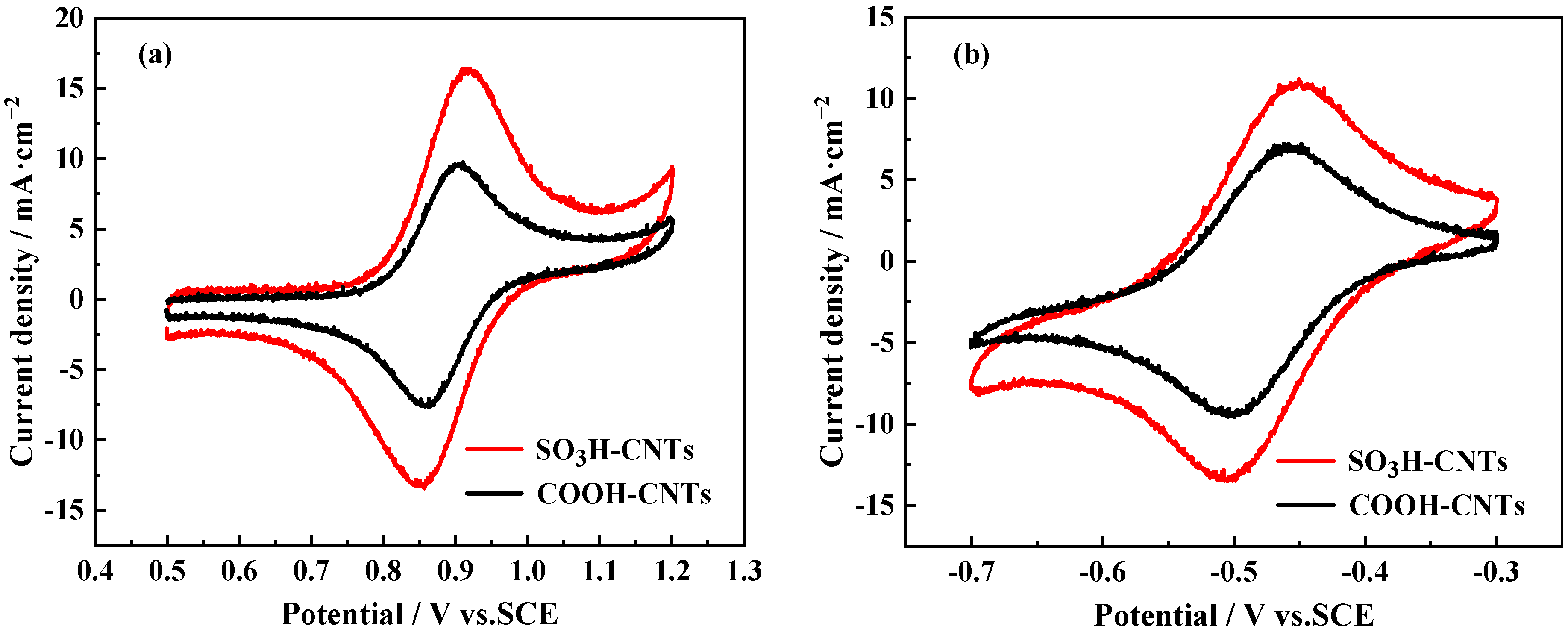
2.1. Electrochemical Properties of Taurine-Functionalized CNTs

Cyclic voltammetry was employed to assess the electrochemical performance of CNTs for the VO2+/VO2+ and V3+/V2+ redox reactions. The results depicted in Figure 1a demonstrate that the anodic and cathodic peak current densities of the VO2+/VO2+ redox reaction show an initial rise, followed by a decline as the reaction temperature increases, reaching its maximum at 60 °C. As the temperature rises further, there is a decrease in the peak current density due to the easy delocalization of carboxyl groups on the CNTs at elevated temperatures, consequently reducing the number of reaction sites [31]. The results obtained for the V3+/V2+ redox reaction, depicted in Figure 1b, indicate that the peak current density attains its highest value at 60 °C. Consequently, the optimal treatment temperature was determined to be 60 °C.
The study examined the efficiency of catalysts in facilitating redox reactions involving VO2+/VO2+ and V2+/V3+ by analyzing the impact of varying mixing durations on the performance of the catalysts. Figure 1c displays the maximum current density observed at the anode and cathode during the redox reaction involving VO2+/VO2+. As depicted in the figure, both peak current densities exhibit an increase as the mixing time progresses from 0 to 4 h, with no substantial changes in the peak current density observed after 2 h. Similarly, in Figure 1d, the maximum current density observed at the anode and cathode for the V2+/V3+ redox reactions does not exhibit a notable rise, even following a duration of 2 h. This is because the modification reaction between CNTs and taurine has reached equilibrium, with the reaction value reaching saturation. This finding led to the conclusion that the most effective reaction time for the combination of taurine and CNTs was 2 h.

2.2. Effect of Taurine-Functionalized CNTs on the Redox Reactivity of Vanadium Ions

The electrocatalytic activity of sulfonated CNTs (SO3H-CNTs) produced through optimized treatment parameters is subsequently evaluated and contrasted with the catalytic efficiency of COOH-CNTs. Figure 2a shows the cyclic voltammograms of 0.1 M VO2+ and 0.1 M VO2+ at SO3H-CNTs and COOH-CNTs electrodes in 2 M H2SO4 as the supporting electrolyte. In both voltammograms, the peak at 0.910 V corresponds to the oxidation of VO2+ to VO2+, while the peak at 0.862 V corresponds to the reduction of VO2+ to VO2+. Similarly, Figure 2b displays the cyclic voltammograms of 0.1 M V2+ and 0.1 M V3+ at the same two electrodes in 2 M H2SO4 as the supporting electrolyte. In these voltammograms, the peak at −0.449 V corresponds to the oxidation of V2+ to V3+, while the peak at −0.500 V corresponds to the reduction of V3+ to V2+. Several electrochemical parameters measured for the VO2+/VO2+ redox pair and the V2+/V3+ pair at the two electrodes are tabulated in Table 1 and Table 2, respectively. The reactivity of SO3H-CNTs is notably superior to that of the COOH-CNTs, as illustrated in Figure 2a. At the positive electrode, the anodic and cathodic peak current densities of the SO3H-CNTs electrode (Jpa and Jpc) are 16.40 and −13.42 mA∙cm−2, respectively. The values showed a 68.21% and 75.65% increase compared to Jpa of 9.75 mA∙cm−2 and Jpc of −7.64 mA∙cm−2 at the COOH-CNTs electrode. Jpc/Jpa serves as an indicator of the reversibility of the electrode reactions [32]. The Jpc/Jpa value of SO3H-CNTs is higher than that of COOH-CNTs, indicating enhanced electrode reversibility. The Jpa and Jpc values for COOH-CNTs are 7.21 and −9.54 mA∙cm−2, respectively, at the negative electrode. The SO3H-CNTs electrode exhibited a Jpa of 11.17 mA∙cm−2 and a Jpc of −13.5 mA∙cm−2, showing a 54.92% and 41.51% increase. The presence of SO3H-CNTs significantly enhances the electrochemical reactivity of vanadium ions in electrode reactions.
Cyclic voltammetry was performed on COOH-CNTs and SO3H-CNTs by increasing the potential scan rate from 10 to 50 mV/s to examine the redox reaction kinetics of CNTs. The cyclic voltammograms of 0.1 M VOSO4 at COOH-CNT and SO3H-CNT electrodes in 2 M H2SO4 at the positive electrode are depicted in Figure 3a and Figure 3b, respectively. Similarly, the cyclic voltametric profiles of COOH-CNTs and SO3H-CNTs at the negative electrode are illustrated in Figure 4a and Figure 4b, respectively.
The findings reveal that the current density of the oxidation and reduction peaks at both electrodes increased with the scan rate, and that the oxidation peak shifted positively and the reduction peak shifted negatively as the scan rate was increased from 10 to 50 mV/s. This suggests that the reactions involving the electron pairs VO2+/VO2+ and V2+/V3+ exhibit reversibility [33]. The peak current density at the SO3H-CNTs electrode is notably higher than that at the COOH-CNTs electrode over the entire range of the scan rate, indicating improved catalytic activity at the former.
The determination of the diffusion coefficient of vanadium ions in the electrolyte can be achieved by analyzing the correlation between the peak current and the potential scan rate [34], as demonstrated in the equation:
I p = 2.69 × 10 5 A D 0 1 / 2 n 3 / 2 v 1 / 2 C
where Ip is the peak current; A is the true surface area of the electrode; D0 is the diffusion coefficient; C is the bulk concentration of the reactants; n is the number of electrons gained or lost in the electrode reaction; and v denotes the scan rate in cyclic voltammetry [35]. As shown in Figure 3c and Figure 4c, the slope can intuitively demonstrate the diffusion ability of the electrolyte through a graphical representation of the square root of the peak current against the scan rate.
The data presented in Figure 3c and Figure 4c illustrate that the peak current has a strong linear correlation with v1/2 of the potential, suggesting that the diffusion step governs the reaction on both electrodes. The linear equation representing the results obtained at the SO3H-CNTs electrode shows a larger slope than that at the COOH-CNTs electrode, indicating an improved diffusion of the active substance, diminishing concentration polarization and elevating the pace of the electrode reactions.

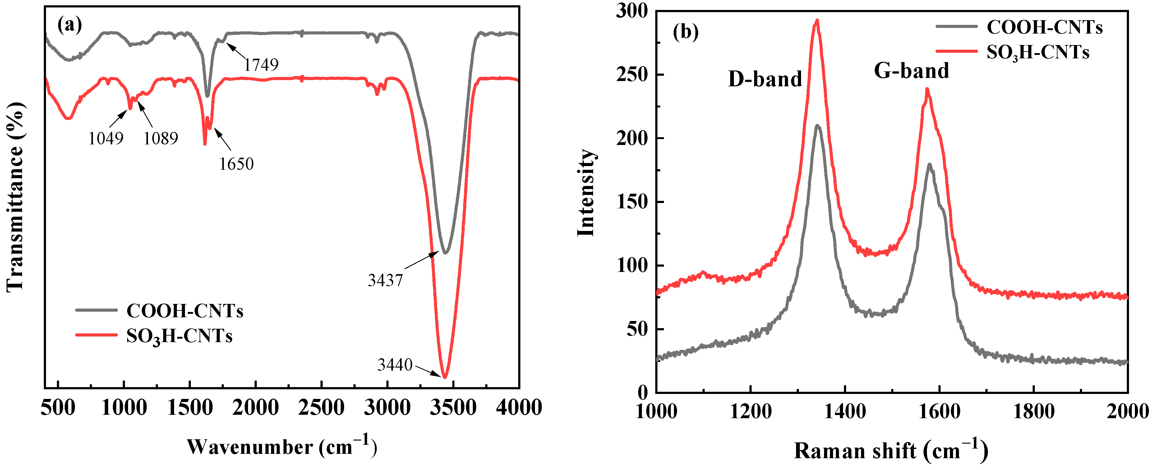
2.3. Effect of Taurine-Functionalized CNTs on their Molecular Composition

X-ray photoelectron spectroscopy measurements were conducted on COOH-CNTs and SO3H-CNTs to analyze their elemental composition within the binding energy spectrum of 0–1350 eV. The respective spectrum is shown in Figure 5a.
Notably, the spectrum of COOH-CNTs exhibits two distinct peaks at 285 and 531 eV, where the aforementioned phenomena are ascribed to the C1s and O1s binding energies, respectively [36,37]. In contrast, SO3H-CNTs exhibit a small new peak at 169 eV, attributed to S2p [38], and a new small peak at 401 eV, attributed to N1s [39]. Quantitative analyses confirm that the elemental N and S content is 0.63% and 0.14%, respectively. The analysis confirms the presence of carbon (C), oxygen (O), sulfur (S), and nitrogen (N) on the surface of the SO3H-CNTs.
The high-resolution N1s X-ray photoelectron spectrum for SO3H-CNTs, depicted in Figure 5b, shows two peaks at 398.83 and 401.53 eV, which are assigned to -NH- and -(O=C)-N, respectively [40]. Additionally, the corresponding high-resolution S2p X-ray photoelectron spectrum in Figure 5c shows two peaks at 168.67 and 172.76 eV, corresponding to the C-SO3H and C-S bonds, respectively. This indicates the chemical bonding of the sulfonic acid group to the carbon backbone. The sulfonic acid group is effectively incorporated onto the surface of the carbon nanotube.
The surface functional groups of the CNT samples were analyzed using infrared spectroscopy, with the results being depicted in Figure 6a. In the case of COOH-CNTs, the peaks at 1749 cm−1 and 3437 cm−1 are attributed to the stretching vibrations associated with -COOH and -OH, respectively. Conversely, in SO3H-CNTs, two additional peaks emerge at 1049 cm−1 and 1089 cm−1, representing the symmetric and asymmetric vibration modes of -SO3H, respectively [41]. Additionally, the -COOH peak at 1749 cm−1 is attenuated and transformed into the amide bond peak at 1650 cm−1. The heightened intensity observed at 3440 cm−1 is attributed to the concurrent stretching vibration of -OH and sulfonic acid moieties. The findings from FTIR substantiate the effective incorporation of sulfonic acid groups onto the carbon nanotube surface, thereby generating supplementary reactive sites conducive to electrode redox reactions.
The Raman spectra of CNTs are depicted in Figure 6b. The two specimens exhibit comparable Raman spectra, featuring two prominent peaks referred to as the D and G bands at 1340 and 1580 cm−1, respectively. The peak observed at 1340 cm−1 signifies disordered graphite (D band), while the peak at 1580 cm−1 is associated with sp2 hybrid carbon atoms (G band). The G band intensity and D band intensity ratio (ID/IG) is commonly used as an indicator to assess defects in disordered carbon materials. Accordingly, an ID/IG of 1.32 for SO3H-CNTs is higher than 1.16 for COOH-CNTs, indicating more structural defect sites in the former, leading to a highly disordered carbon structure. The alteration of carbon structure and the increase in surface defects enhance the electrochemical reactivity.
The discussion pertains to the electrocatalytic mechanism of the sulfonic acid group that is developed on the CNT catalysts for facilitating redox reactions involving VO2+/VO2+ and V3+/V2+. This analysis is based on the existing literature [42] and experimental results. This is illustrated in Figure 7. The procedure of charging and discharging comprises a series of discrete stages. Initially, an ion exchange mechanism takes place, wherein vanadium ions within the electrolyte migrate to the electrode surface and establish coordination bonds with the sulfonic acid groups present on the surface of CNTs. Subsequently, an electron transfer process occurs, facilitated by the S-O-V bond, enabling efficient electron transport. Finally, vanadium ions resulting from oxidation or reduction reactions detach from the electrode surface due to their coordination with sulfonic acid groups and diffuse back into the electrolyte. Taurine plays a crucial role as a facilitator in the mass transfer mechanism and as a mediator in the charge transfer process during the electrode reaction, accelerating the electrode reaction rate of vanadium ions. The hydrogen atom in the sulfonic acid group dissociates more readily than the -COOH group due to the pronounced electron-withdrawing influence exerted by the two oxygen atoms on the sulfur atom within the sulfonic acid group. Consequently, vanadium ions exhibit a stronger attraction towards the S-O bond in comparison to the C-O bond, leading to an acceleration in the redox reaction rate.

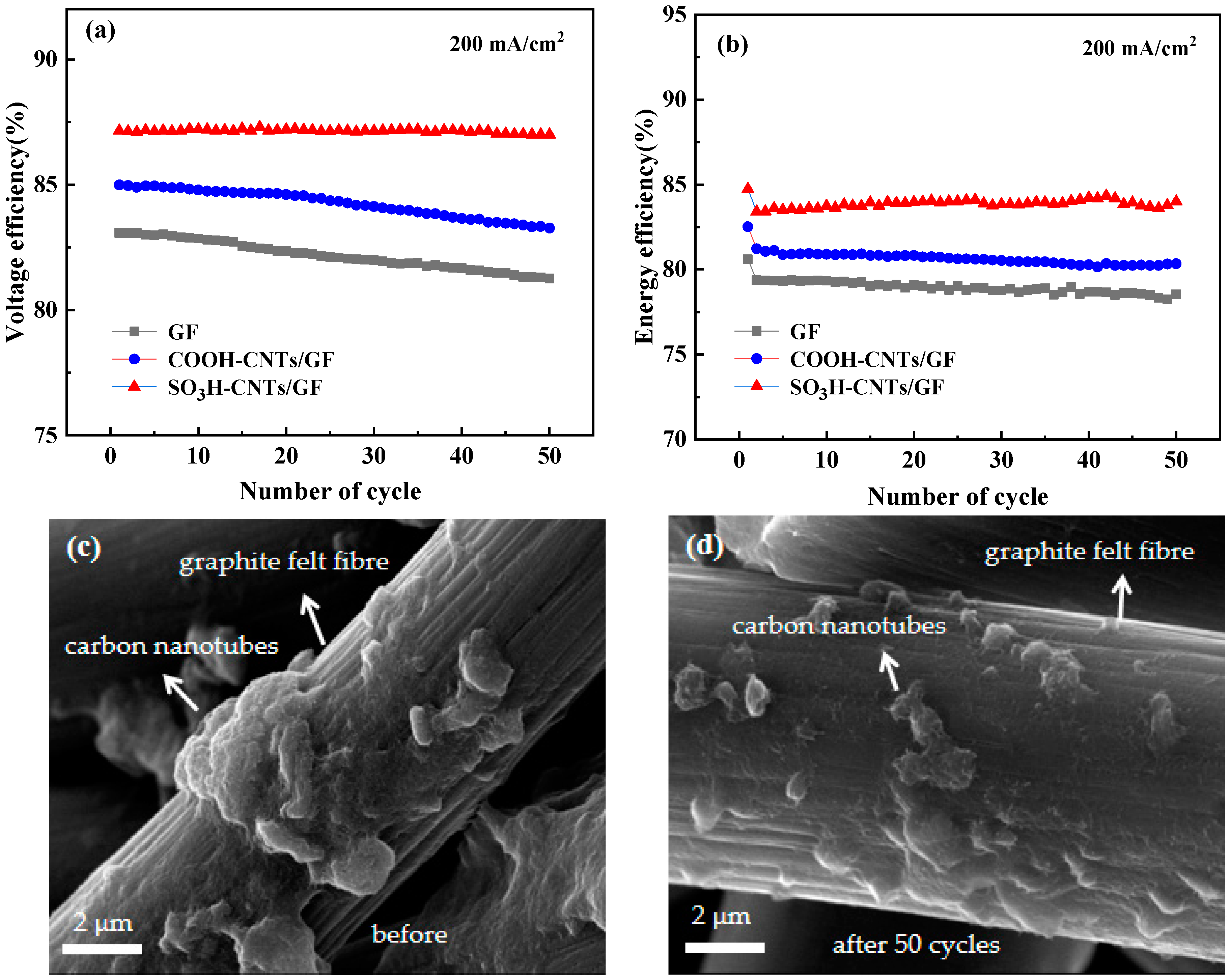
2.4. The Performance Evaluations of VRFB

To clarify the function of SO3H-CNTs in the implementation of the VRFB, individual batteries were constructed using untreated graphite felt and graphite felt coated with catalysts (COOH-CNTs and SO3H-CNTs) as the positive and negative electrodes. Charge–discharge experiments were conducted using an individual battery.
To compare the charge and discharge voltages and capacities of batteries with three different electrodes, constant current charge and discharge experiments were conducted at a current density of 100 mA∙cm−2. The results are presented in Figure 8a. The battery using SO3H-CNTs has a charging capacity of 1.08 Ah and a discharging capacity of 0.99 Ah. The battery containing COOH-CNTs has a charging capacity of 0.99 Ah and a discharging capacity of 0.90 Ah, while the battery with blank graphite felt (GF) has a charging capacity of 0.86 Ah and a discharging capacity of 0.78 Ah. The use of SO3H-CNTs/GF electrodes increases the charge capacity by 25.58% and the discharge capacity by 26.92% compared to conventional GF electrodes. A battery using SO3H-CNTs as electrocatalysts shows lower charge voltages and higher discharge voltages. The graphite felts coated with SO3H-CNTs show improved electrochemical activity, leading to decreased electrochemical polarization. This phenomenon benefits from the reduction in battery overpotential and the enhancement of its capacity.
To analyze thoroughly the impact of sulfonated CNTs on the performance of batteries, experiments were conducted to assess the charge and discharge capabilities under varying current densities. The efficiency was assessed across five cycles at various current densities between 100 and 300 mA∙cm−2. Subsequently, the current density was reset to 200 mA∙cm−2. Figure 8b illustrates that the coulombic efficiency of the VRFB remains consistent across the different current densities. However, there are significant differences in their voltage efficiency and energy efficiency, as shown in Figure 8c and Figure 8d, respectively. The battery utilizing SO3H-CNTs/GF as electrodes shows improved voltage efficiency and energy efficiency in comparison to those with untreated GF electrodes. At a current density of 300 mA∙cm−2, the voltage efficiency and energy efficiency values for the battery using GF as the electrode are 75.31% and 72.71%, respectively. The voltage efficiency and energy efficiency of cells using COOH-CNTs/GF electrodes are 78.58% and 75.76%, respectively. The voltage efficiency and energy efficiency of batteries using SO3H-CNTs/GF as electrodes are 81.46% and 78.83%, respectively. In comparison to cells with standard GF electrodes, the improvements are 6.15% and 6.12%, respectively. This trend aligns with the catalytic activity pattern exhibited by the electrodes. The addition of sulfonic acid groups to electrode surfaces increases active sites, improving the electrochemical activity of graphite felts and reducing electrochemical polarization during high-current-density electrode reactions. This indicates that SO3H-CNTs positively affect the electrochemical performance.
To investigate the impact of SO3H-CNTs catalyst on the operational stability and robustness of the VRFB, a 50-cycle charge–discharge experiment was conducted at a current density of 200 mA∙cm−2. The outcomes are depicted in Figure 9a,b, indicating that the voltage and energy efficiencies of the three cells exhibit a relatively stable performance over 50 cycles. The average voltage efficiency of the battery using conventional GF is 81.75%, with an energy efficiency of 78.71%. The average voltage efficiency and energy efficiency of batteries using COOH-CNTs/GF are 83.85% and 80.42%, respectively. The average voltage efficiency and energy efficiency of batteries using SO3H-CNTs/GF are 87.12% and 83.95%, respectively, showing an increase of 5.37% and 5.24% compared to conventional cells. This phenomenon is attributed to the use of SO3H-CNTs as catalysts, which improves the electrochemical activity by facilitating mass transfer and reducing the activation energy of the reaction. Even when exposed to highly acidic electrolyte conditions (3 M H2SO4), SO3H-CNTs maintained their catalytic activity over a prolonged period. Figure 9c,d show scanning electron micrographs of graphite felt coated with SO3H-CNTs. In Figure 9c, the successful adhesion of CNTs to the surface of the graphite felt is evident. In Figure 9d, it is clear that even after 50 cycles, a portion of CNTs remain firmly attached to the graphite felt.

3. Experimental Section

3.1. Materials

Carboxylic acid functionalized multi-walled CNTs (COOH-CNTs, >95%, outer diameter: 5–15 nm, inner diameter: 2–5 nm, length: 0.5–2 µm, 3.86 wt% carboxylic acid functionalized) were purchased from Xianfeng Nano Materials Technology Co. Ltd. (Nanjing, China). Taurine was purchased from Shanghai Maclin Biochemical Technology Co. Ltd. (Shanghai, China). N-Methylpyrrolidone (NMP) and Nafion 117 solution (~5% in a mixture of lower aliphatic alcohols and water) were purchased from Aladdin (Shanghai, China) and used as received. VOSO4∙nH2O (99 wt%) was acquired from Shanghai Huiyan Chemical Products Co. Ltd. (Shanghai, China).

3.2. Preparation of Functionalized CNTs

In synthesizing sulfonic-acid-functionalized CNTs, 100 mg of taurine was mixed with 2 mL of deionized water, followed by 4 mg of COOH-CNTs. This mixture was heated to a range of temperatures (20 °C, 40 °C, 60 °C, 80 °C, 100 °C) and different durations (0.5 h, 1 h, 2 h, 3 h, 4 h). Afterward, each mixed solution was centrifuged and purified with deionized water five times until a neutral pH was achieved to obtain taurine-modified CNTs. In our study, the changes in the functional groups on CNTs before and after modification were examined using Fourier transform infrared (FTIR) spectroscopy (Thermo Nicolet Nexus 670, Waltham, MA, USA). The chemical characterization of CNTs specimens was assessed using X-ray photoelectron spectroscopy (XPS, Thermo Scientific K-Alpha+, Thermo Fisher, Waltham, MA, USA). The XPS spectra were fit using Avantage 5.9931 software. Raman spectra were acquired by employing a laser as an excitation source on a Raman spectrometer (WITec alpha300R, Ulm, GER).

3.3. Electrochemical Characterizations of Functionalized CNTs

To assess the electrochemical properties of CNTs on vanadium ion redox reactions, cyclic voltammetry was performed using an electrochemical workstation (PARSSTAT 4000A, AMETEK, Berwyn, PA, USA). Cyclic voltammetry was carried out using a standard three-electrode cell consisting of a saturated calomel electrode (SCE; warning: this electrode must be handled with care owing to health risks associated with mercury vapor in the electrode) as the reference electrode, a platinum counter electrode, and a CNTs-coated glassy carbon electrode (GCE; 5 mm diameter) as the working electrode. After ultrasonically mixing 3 mg of CNTs with 1 mL of ethanol for 30 min, 20 µL of a 0.5 wt% Nafion solution was added before the mixture was further ultrasonicated for 10 min to achieve a uniform dispersion. In our work, 30 µL of the solution was applied on a 5 mm diameter glassy carbon electrode, which was then dried using a baking lamp. Electrolytes used in cyclic voltammetry were 0.1 mol/L V4+ + 2 mol/L H2SO4 and 0.1 mol/L V3+ + 2 mol/L H2SO4. A potential window between 0.5 and 1.2 V was used in assessing the anode, while that between −0.3 V and −0.7 V was used in assessing the cathode. The scanning rate for both tests was 10 mV/s.

3.4. The Performance Evaluation of VRFB

A graphite felt was coated with a catalyst in preparation for conducting charge and discharge testing. To prepare the catalyst ink, 10 mg of CNTs was ultrasonically mixed with 10 mL of NMP for 60 min to achieve a homogeneous dispersion. A 3 × 3 × 0.5 cm3 graphite felt was incubated in the ink for 12 h before being dried at 100 °C for 10 h to prepare a CNTs-coated graphite felt.
A single cell was assembled using catalyst-coated graphite felts as negative and positive electrodes. A Nafion 117 ion-exchange membrane (5 cm × 5 cm, Dupont, Minneapolis, MN, USA) was used as a separator. The charge and discharge tests were conducted utilizing the LANHE CT2001A (5 V/10 A) battery test system from Wuhan Electronic Technology Co. Ltd. (Wuhan, China). The current density was increased from 100 mA∙cm−2 to 300 mA∙cm−2 during the tests. An electrolyte consisting of 30 mL of a solution containing 1.5 mol/L VO2+ and 3 mol/L H2SO4 was used in an anodic scan, and an electrolyte consisting of 30 mL of a solution containing 1.5 mol/L V3+ and 3 mol/L H2SO4 was used in a cathodic scan. The charge and discharge voltages were maintained within the range of 1.65 V and 0.65 V, respectively. The flow rate for the electrolyte circulation was set at 60 mL·min−1. All experiments were conducted under ambient conditions.

4. Conclusions

In this investigation, taurine-functionalized CNTs were used as catalysts to improve the electrochemical efficiency of the VRFB. The SO3H-CNTs were prepared through a simple modification process involving treating COOH-CNTs with a taurine solution. The electrocatalytic activities of SO3H-CNTs were compared to those of the COOH-CNTs. At the positive electrode, the peak anodic and cathodic current densities (Jpa and Jpc) of SO3H-CNTs were 16.40 and −13.42 mA∙cm−2, respectively. These values have exceeded those of COOH-CNTs (Jpa: 9.75 mA∙cm−2, Jpc: −7.64 mA∙cm−2). At the negative electrode, the Jpa and Jpc of SO3H-CNTs were 11.17 and −13.50 mA∙cm−2, respectively. These values exceed those of COOH-CNTs (Jpa: 7.21 mA∙cm−2, Jpc: −9.54 mA∙cm−2). The results show a significant improvement in the electrocatalytic activity of CNTs after being modified with taurine. The hydrophilic sulfonic acid groups act as active sites for the redox reactions involving VO2+/VO2+ and V3+/V2+, improving the transport of electrolyte active species at the electrode interface and accelerating the electrochemical reaction kinetics.
Based on single-cell tests on the VRFB, the battery using SO3H-CNTs-coated graphite felts as electrodes shows a higher voltage efficiency and energy efficiency compared to the battery utilizing COOH-CNTs-coated graphite felts and a pristine battery. The battery using SO3H-CNTs/GF electrodes shows greater charge–discharge capacity than the battery with conventional graphite felt electrodes. At a current density of 300 mA∙cm−2, the voltage efficiency and energy efficiency of a battery using SO3H-CNTs/GF as electrodes are 81.46% and 78.83%, respectively. These values reflect a 6.15% and 6.12% increase compared to batteries with GF electrodes. During a 50-turn charge–discharge experiment at a current density of 200 mA∙cm−2, the battery using SO3H-CNTs/GF maintains an energy efficiency of 83.95%, which is 5.24% higher than the original battery. This study shows that taurine-functionalized CNTs are efficient catalysts for the electrodes of the VRFB, with significant potential for practical use.

Author Contributions

Conceptualization, L.W.; methodology, L.W.; software, L.W.; validation, L.W., H.L. and L.G.; formal analysis, L.W.; investigation, L.W.; resources, T.L. and Y.Z.; data curation, L.W.; writing—original draft preparation, L.W.; writing—review and editing, T.L., Y.Z. and H.L.; visualization, H.L. and L.G.; supervision, T.L.; project administration, T.L. and Y.Z.; funding acquisition, Y.Z. and H.L. All authors have read and agreed to the published version of the manuscript.

Funding

This work was financially supported by the National Key R&D Program of China (2023YFC3903900), the Science and technology innovation Talent program of Hubei Province (2022EJD002), and the Natural Science Foundation of Hubei Province of China (2023AFB061).

Data Availability Statement

Data are contained within the article.

Conflicts of Interest

The authors declare no conflict of interest.

References

  1. Anser, M.K.; Hanif, I.; Vo, X.V.; Alharthi, M. The long-run and short-run influence of environmental pollution, energy consumption, and economic activities on health quality in emerging countries. Environ. Sci. Pollut. Res. 2020, 27, 32518–32532. [Google Scholar] [CrossRef] [PubMed]
  2. Fetyan, A.; El-Nagar, G.A.; Lauermann, I.; Schnucklake, M.; Schneider, J.; Roth, C. Detrimental role of hydrogen evolution and its temperature-dependent impact on the performance of vanadium redox flow batteries. J. Energy Chem. 2019, 32, 57–62. [Google Scholar] [CrossRef]
  3. Emmel, D.; Kunz, S.; Blume, N.; Kwon, Y.; Turek, T.; Minke, C.; Schröder, D. Benchmarking organic active materials for aqueous redox flow batteries in terms of lifetime and cost. Nat. Commun. 2023, 14, 6672. [Google Scholar] [CrossRef] [PubMed]
  4. Sánchez-Díez, E.; Ventosa, E.; Guarnieri, M.; Trovò, A.; Flox, C.; Marcilla, R.; Soavi, F.; Mazur, P.; Aranzabe, E.; Ferret, R. Redox flow batteries: Status and perspective towards sustainable stationary energy storage. J. Power Sources 2021, 481, 228804. [Google Scholar] [CrossRef]
  5. Pearre, N.; Swan, L. Combining wind, solar, and in-stream tidal electricity generation with energy storage using a load-perturbation control strategy. Energy 2020, 203, 117898. [Google Scholar] [CrossRef]
  6. Zhang, D.; Li, C.; Lin, N.; Xie, B.; Chen, J. Mica-stabilized polyethylene glycol composite phase change materials for thermal energy storage. Int. J. Miner. Met. Mater. 2022, 29, 168–176. [Google Scholar] [CrossRef]
  7. Sharma, J.; Kulshrestha, V. Advancements in polyelectrolyte membrane designs for vanadium redox flow battery (VRFB). Results Chem. 2023, 5, 100892. [Google Scholar] [CrossRef]
  8. Zhang, M.; Wang, G.; Li, F.; He, Z.; Zhang, J.; Chen, J.; Wang, R. High conductivity membrane containing polyphosphazene derivatives for vanadium redox flow battery. J. Membr. Sci. 2021, 630, 119322. [Google Scholar] [CrossRef]
  9. Lv, Y.; Han, C.; Zhu, Y.; Zhang, T.; Yao, S.; He, Z.; Dai, L.; Wang, L. Recent advances in metals and metal oxides as catalysts for vanadium redox flow battery: Properties, structures, and perspectives. J. Mater. Sci. Technol. 2021, 75, 96–109. [Google Scholar] [CrossRef]
  10. Minke, C.; Ledesma, M.A.D. Impact of cell design and maintenance strategy on life cycle costs of vanadium redox flow batteries. J. Energy Storage 2019, 21, 571–580. [Google Scholar] [CrossRef]
  11. Liu, H.; Zhang, Y.-M.; Liu, T.; Huang, J.; Chen, L.-M.; Hu, Y.-W. Preparation of vanadium electrolyte from vanadium shale leaching solution with high concentration chloride using D2EHPA. Trans. Nonferrous Met. Soc. China 2023, 33, 1594–1608. [Google Scholar] [CrossRef]
  12. Alphonse, P.-J.; Taş, M.; Elden, G. Novel electrode design having gradually increasing porosity in a vanadium redox flow battery. Fuel 2023, 333, 126198. [Google Scholar] [CrossRef]
  13. Roznyatovskaya, N.; Noack, J.; Pinkwart, K.; Tübke, J. Aspects of electron transfer processes in vanadium redox-flow batteries. Curr. Opin. Electrochem. 2020, 19, 42–48. [Google Scholar] [CrossRef]
  14. Jeong, K.I.; Jeong, J.-M.; Oh, J.; Lim, J.W.; Kim, S.S. An integrated composite structure with reduced electrode/bipolar plate contact resistance for vanadium redox flow battery. Compos. B Eng. 2022, 233, 109657. [Google Scholar] [CrossRef]
  15. Bayeh, A.W.; Kabtamu, D.M.; Chang, Y.-C.; Wondimu, T.H.; Huang, H.-C.; Wang, C.-H. Carbon and metal-based catalysts for vanadium redox flow batteries: A perspective and review of recent progress. Sustain. Energy Fuels 2021, 5, 1668–1707. [Google Scholar] [CrossRef]
  16. Abbas, S.; Lee, H.; Hwang, J.; Mehmood, A.; Shin, H.-J.; Mehboob, S.; Lee, J.-Y.; Ha, H.Y. A novel approach for forming carbon nanorods on the surface of carbon felt electrode by catalytic etching for high-performance vanadium redox flow battery. Carbon 2018, 128, 31–37. [Google Scholar] [CrossRef]
  17. Park, S.E.; Lee, K.; Suharto, Y.; Kim, K.J. Enhanced electrocatalytic performance of nitrogen- and phosphorous-functionalized carbon felt electrode for VO2+/VO2+ redox reaction. Int. J. Energy Res. 2021, 45, 1806–1817. [Google Scholar] [CrossRef]
  18. Pasala, V.; Ramavath, J.N.; He, C.; Ramani, V.K.; Ramanujam, K. N- and P-co-doped Graphite Felt Electrode for Improving Positive Electrode Chemistry of the Vanadium Redox Flow Battery. ChemistrySelect 2018, 3, 8678–8687. [Google Scholar] [CrossRef]
  19. Hou, B.; Cui, X.; Chen, Y. In situ TiO2 decorated carbon paper as negative electrode for vanadium redox battery. Solid State Ion. 2018, 325, 148–156. [Google Scholar] [CrossRef]
  20. Zhou, A.; Shao, X.; Li, D.; Du, Y.; Zhang, Y.; Cao, L.; Yang, J. Heteroatom co-doped biomass carbon modified electrodes for all-vanadium redox flow batteries with ultra-low decay rate of energy efficiency. J. Power Sources 2024, 591, 233890. [Google Scholar] [CrossRef]
  21. Li, W.; Liu, J.; Yan, C. The electrochemical catalytic activity of single-walled carbon nanotubes towards VO2+/VO2+ and V3+/V2+ redox pairs for an all vanadium redox flow battery. Electrochim. Acta 2012, 79, 102–108. [Google Scholar] [CrossRef]
  22. González, Z.; Álvarez, P.; Blanco, C.; Vega-Díaz, S.; Tristán-López, F.; Rajukumar, L.P.; Cruz-Silva, R.; Elías, A.L.; Terrones, M.; Menéndez, R. The influence of carbon nanotubes characteristics in their performance as positive electrodes in vanadium redox flow batteries. Sustain. Energy Technol. Assess. 2015, 9, 105–110. [Google Scholar] [CrossRef]
  23. Hwang, S.; Jeong, S.-H. Stretchable carbon nanotube conductors and their applications. Korean J. Chem. Eng. 2016, 33, 2771–2787. [Google Scholar] [CrossRef]
  24. Yang, H.; Fan, C.; Zhu, Q. Sucrose pyrolysis assembling carbon nanotubes on graphite felt using for vanadium redox flow battery positive electrode. J. Energy Chem. 2018, 27, 451–454. [Google Scholar] [CrossRef]
  25. Jiang, Q.; Ren, Y.; Yang, Y.; Wang, L.; Dai, L.; He, Z. Recent advances in carbon-based electrocatalysts for vanadium redox flow battery: Mechanisms, properties, and perspectives. Compos. B Eng. 2022, 242. [Google Scholar] [CrossRef]
  26. Dai, L.; Jiang, Y.; Meng, W.; Zhou, H.; Wang, L.; He, Z. Improving the electrocatalytic performance of carbon nanotubes for VO2+/VO2+ redox reaction by KOH activation. Appl. Surf. Sci. 2017, 401, 106–113. [Google Scholar] [CrossRef]
  27. Wang, S.; Zhao, X.; Cochell, T.; Manthiram, A. Nitrogen-Doped Carbon Nanotube/Graphite Felts as Advanced Electrode Materials for Vanadium Redox Flow Batteries. J. Phys. Chem. Lett. 2012, 3, 2164–2167. [Google Scholar] [CrossRef] [PubMed]
  28. Lin, J.; Shang, Y.; Lin, X.; Yang, L.; Yu, A. Study on Nitrogen-Doped Carbon Nanotubes for Vanadium Redox Flow Battery Application. Int. J. Electrochem. Sci. 2016, 11, 665–674. [Google Scholar] [CrossRef]
  29. Moon, S.; Kwon, B.W.; Chung, Y.; Kwon, Y. Effect of Bismuth Sulfate Coated on Acidified CNT on Performance of Vanadium Redox Flow Battery. J. Electrochem. Soc. 2019, 166, A2602–A2609. [Google Scholar] [CrossRef]
  30. Chung, Y.; Noh, C.; Kwon, Y. Role of borate functionalized carbon nanotube catalyst for the performance improvement of vanadium redox flow battery. J. Power Sources 2019, 438, 227063. [Google Scholar] [CrossRef]
  31. Zhou, A.L.; Wang, H.J.; Fu, X.B.; Peng, F.; Xu, H. Effect of acid oxidation treatment on Surface groups of Multi-walled carbon nanotubes. New Chem. Mater. 2007, 35, 37–39. [Google Scholar]
  32. Ghimire, P.C.; Schweiss, R.; Scherer, G.G.; Wai, N.; Lim, T.M.; Bhattarai, A.; Nguyen, T.D.; Yan, Q. Titanium carbide-decorated graphite felt as high performance negative electrode in vanadium redox flow batteries. J. Mater. Chem. A 2018, 6, 6625–6632. [Google Scholar] [CrossRef]
  33. Noh, C.; Kwon, B.W.; Chung, Y.; Kwon, Y. Effect of the redox reactivity of vanadium ions enhanced by phosphorylethanolamine based catalyst on the performance of vanadium redox flow battery. J. Power Sources 2018, 406, 26–34. [Google Scholar] [CrossRef]
  34. Jelyani, M.Z.; Rashid-Nadimi, S.; Asghari, S. Treated carbon felt as electrode material in vanadium redox flow batteries: A study of the use of carbon nanotubes as electrocatalyst. J. Solid State Electrochem. 2017, 21, 69–79. [Google Scholar] [CrossRef]
  35. Ramasahayam, S.K.; Azam, S.; Viswanathan, T. Phosphorous, nitrogen co-doped carbon from spent coffee grounds for fuel cell applications. J. Appl. Polym. Sci. 2015, 132, 41948. [Google Scholar] [CrossRef]
  36. Noh, C.; Moon, S.; Chung, Y.; Kwon, Y. Chelating functional group attached to carbon nanotubes prepared for performance enhancement of vanadium redox flow battery. J. Mater. Chem. A 2017, 5, 21334–21342. [Google Scholar] [CrossRef]
  37. He, Z.; Jiang, Y.; Meng, W.; Zhu, J.; Liu, Y.; Dai, L.; Wang, L. Advanced LiTi2(PO4)3@N-doped carbon anode for aqueous lithium ion batteries. Electrochim. Acta 2016, 222, 1491–1500. [Google Scholar] [CrossRef]
  38. Li, C.; Xie, B.; Chen, J.; He, J.; He, Z. Enhancement of nitrogen and sulfur co-doping on the electrocatalytic properties of carbon nanotubes for VO2+/VO2+ redox reaction. RSC Adv. 2017, 7, 13184–13190. [Google Scholar] [CrossRef]
  39. Kabtamu, D.M.; Chen, J.-Y.; Chang, Y.-C.; Wang, C.-H. Water-activated graphite felt as a high-performance electrode for vanadium redox flow batteries. J. Power Sources 2017, 341, 270–279. [Google Scholar] [CrossRef]
  40. Shin, M.; Noh, C.; Chung, Y.; Kim, D.-H.; Kwon, Y. Vanadium redox flow battery working even at a high current density by the adoption of tris(hydroxymethyl) aminomethane functionalized acidified carbon nanotube catalyst. Appl. Surf. Sci. 2021, 550, 148977. [Google Scholar] [CrossRef]
  41. Tamborini, L.; Casco, M.; Militello, M.; Silvestre-Albero, J.; Barbero, C.; Acevedo, D. Sulfonated porous carbon catalysts for biodiesel production: Clear effect of the carbon particle size on the catalyst synthesis and properties. Fuel Process. Technol. 2016, 149, 209–217. [Google Scholar] [CrossRef]
  42. Ge, L.; Liu, T.; Zhang, Y.; Liu, H. Characterization and comparison of organic functional groups effects on electrolyte performance for vanadium redox flow battery. Front. Chem. Sci. Eng. 2023, 17, 1221–1230. [Google Scholar] [CrossRef]
Figure 1. Peak current density at functionalized CNTs: (a) VO2+/VO2+ redox reactions at different treatment temperatures, (b) V2+/V3+ redox reactions at different treatment temperatures, (c) VO2+/VO2+ at different treatment times, and (d) V2+/V3+ redox reactions at different treatment times.
Catalysts 14 00281 g001
Figure 2. Cyclic voltammograms of (a) 0.1 M VO2+ and 0.1 M VO2+ and (b) 0.1 M V2+ and 0.1 M V3+ at COOH-CNT and SO3H-CNT electrodes in 2 M H2SO4 supporting electrolyte. Scan rate: 10 mV·s−1.
Catalysts 14 00281 g002
Figure 3. Cyclic voltammetry plots were obtained using an electrolyte solution containing 0.1 M VOSO4 + 2 M H2SO4 for (a) COOH-CNTs and (b) SO3H-CNTs at scan rate from 10 to 50 mV∙s−1; (c) peak current density as a functional of the square root of the scan rate.
Catalysts 14 00281 g003
Figure 4. Cyclic voltammetry plots were obtained using an electrolyte solution containing 0.1 M V3+ + 2 M H2SO4 for (a) COOH-CNTs and (b) SO3H-CNTs at scan rate from 10 to 50 mV∙s−1; (c) peak current density as a functional of the square root of the scan rate.
Catalysts 14 00281 g004
Figure 5. (a) X-ray photoelectron spectra of COOH-CNTs and SO3H-CNTs, (b) high-resolution X-ray photoelectron spectra of SO3H-CNTs for N1s, (c) high-resolution X-ray photoelectron spectra of SO3H-CNTs for S2p. The black line represents the original data, while the red line represents the fitted data.
Catalysts 14 00281 g005
Figure 6. (a) The infrared spectrum of COOH-CNTs and SO3H-CNTs; (b) Raman spectrum of COOH-CNTs and SO3H-CNTs.
Catalysts 14 00281 g006
Figure 7. The catalytic process of SO3H-CNTs in relation to (a) VO2+/VO2+ and (b) V2+/V3+.
Catalysts 14 00281 g007
Figure 8. (a) Charge–discharge capacity, (b) coulombic efficiencies, (c) voltage efficiencies, and (d) energy efficiencies of VRFB.
Catalysts 14 00281 g008
Figure 9. (a) Voltage efficiencies and (b) energy efficiencies of the VRFB, (c) scanning electron micrograph of the composite electrode, (d) scanning electron micrograph of the composite electrode after 50 cycles.
Catalysts 14 00281 g009
Table 1. Electrochemical property of catalyst in 0.1 M VOSO4 + 2 M H2SO4 solution.
VO2+/VO2+Peak Current Density (mA∙cm−2)Peak Potential (V)∆E/VJpc/Jpa
AnodicCathodicAnodicCathodic
COOH-CNTs9.75−7.640.9100.8620.0480.784
SO3H-CNTs16.40−13.420.9200.8570.0630.818
Table 2. Electrochemical property of catalyst in 0.1 M V3+ + 0.2 M H2SO4 solution.
V2+/V3+Peak Current Density (mA∙cm−2)Peak Potential (V)∆E/VJpc/Jpa
AnodicCathodicAnodicCathodic
COOH-CNTs7.21−9.54−0.449−0.5000.0511.323
SO3H-CNTs11.17−13.50−0.450−0.5050.0551.209
Disclaimer/Publisher’s Note: The statements, opinions and data contained in all publications are solely those of the individual author(s) and contributor(s) and not of MDPI and/or the editor(s). MDPI and/or the editor(s) disclaim responsibility for any injury to people or property resulting from any ideas, methods, instructions or products referred to in the content.

