Article

Photodegradation of Wastewater Containing Organic Dyes Using Modified G-C3N4-Doped ZrO2 Nanostructures: Towards Safe Water for Human Beings

by
Ahmed T. Mosleh
1,2,3,
Fatemah F. Al-Harbi
4,
Soumaya M. Gouadria
4,
Samer H. Zyoud
5,6,7,*,
Heba Y. Zahran
8,
Mai S. A. Hussien
1,2 and
Ibrahim S. Yahia
8
1
Department of Chemistry, Faculty of Education, Ain Shams University, Roxy, Cairo 11757, Egypt
2
Nanoscience Laboratory for Environmental and Bio-Medical Applications (NLEBA), Green Research Laboratory (GRL), Faculty of Education, Ain Shams University, Roxy, Cairo 11757, Egypt
3
Nanotechnology Section, Egyptian Company for Carbon Materials, El-Sheraton/El-Nozha, Cairo 11757, Egypt
4
Department of Physics, College of Science, Princess Nourah bint Abdulrahman University, P.O. Box 84428, Riyadh 11671, Saudi Arabia
5
Department of Mathematics and Sciences, Ajman University, Ajman P.O. Box 346, United Arab Emirates
6
Center of Medical and Bio-Allied Health Sciences Research (CMBHSR), Ajman University, Ajman P.O. Box 346, United Arab Emirates
7
Nonlinear Dynamics Research Center (NDRC), Ajman University, Ajman P.O. Box 346, United Arab Emirates
8
Laboratory of Nano-Smart Materials for Science and Technology (LNSMST), Department of Physics, Faculty of Science, King Khalid University, P.O. Box 9004, Abha 61413, Saudi Arabia
*
Author to whom correspondence should be addressed.
Catalysts 2024, 14(1), 42; https://doi.org/10.3390/catal14010042
Submission received: 1 November 2023 / Revised: 30 November 2023 / Accepted: 15 December 2023 / Published: 7 January 2024
(This article belongs to the Special Issue Innovative Functional Materials in Photocatalysis, 2nd Edition)

Abstract

:
Historically, the photocatalytic efficacy of graphitic carbon nitride (g-C3N4) has been constrained by a rapid charge recombination rate and restricted sensitivity to visible light. To overcome these limitations and enhance the performance of g-C3N4, the strategic formation of heterojunctions with semiconductor materials is deemed the optimal approach. The present study employed a facile sonication-assisted pyrolysis method to synthesize a g-C3N4@ZrO2 nanocomposite photocatalyst. This hybrid material was characterized extensively using a comprehensive suite of analytical techniques, including XRD, SEM, EDX, FTIR, and UV-Vis DRS. A comparative analysis of photocatalytic applications under identical conditions was conducted for all synthesized materials, wherein they were subjected to UVc light irradiation. The photocatalytic degradation of various dye models, such as MB, EY, and a combination of dyes, was assessed using the prepared nanocomposites. The g-C3N4@ZrO2 photocatalysts showcased superior photocatalytic performance, with a particular variant, g-CNZ6, exhibiting remarkable activity. With a bandgap energy of 2.57 eV, g-CNZ6 achieved impressive degradation efficiencies of 96.5% for MB and 95.6% for EY within 40 min. Following previous studies, the superoxide radical anions (O2. and h+) were largely accountable for the degradation of MB. Therefore, the observed efficacy of the g-C3N4@ZrO2 nanocomposite photocatalyst can be attributed to the increased generation of these reactive species.

1. Introduction

Human history has been marked by an escalating stress on natural resources, with the past century seeing the most acute increase, principally due to the dramatic surge in the population and the significant demand to feed and sustain such a populace [1]. Numerous global challenges have come to the fore, including mounting demands for, and the scarcity of, freshwater sources, a crisis precipitated by rampant industrialization, a burgeoning population, and relentless aridity [2]. Imperative to environmental preservation is removing hazardous dyes from the wastewater discharge of the industries of textiles and pharmaceuticals [3].
Many water purification techniques have been utilized to cleanse contaminated water, notably reverse osmosis, sedimentation, electrochemical fragmentation, ion exchange, chlorination, and photocatalysis [4,5,6]. Among these, the photocatalytic degradation of harmful pollutants is gaining prominence due to its unique attributes, such as using renewable energy, environmental benignity, and superior efficacy compared to conventional methodologies [7,8]. Solar photocatalysis, which leverages high-efficiency photocatalysts, semiconductor materials, and abundant solar energy, is increasingly recognized by the scientific community as a promising eco-energetic solution [9,10,11,12,13,14,15].
Within materials science, two-dimensional layered materials of graphitic carbon nitride (g-C3N4) have become a focal point due to their semi-conductor nature, manageable energy gap, cost-effectiveness, ease of preparation, high chemical stability, non-polluting feature, and abundant active sites, thereby functioning as an effective metal-free and visible light-responsive photocatalyst [16,17]. g-C3N4, distinguished by its low direct band gap (2.7 eV), has garnered attention for its superior attributes like excellent visible light absorption (>460 nm), remarkable photochemical capabilities, and exceptional thermal and chemical resilience [18,19]. g-C3N4’s structure parallels that of graphite but with layers held together by van der Waals forces and each layer possessing robust covalent C–N bonds instead of C–C bonds. It exhibits substantial stability against thermal and chemical attacks, owing to its “poly (tri-s-triazine)” structure and a high degree of condensation [20].
However, pure g-C3N4’s photocatalytic efficacy is typically limited due to its restricted solar light absorption, small surface area, and short-lived photogenerated electron–hole pairs [21]. As a result, several enhancement strategies have been pursued, including molecular and elemental doping, fabrication, exfoliation to create two-dimensional (2D) nanosheets, combination with conductive materials, nanocomposite structures, and heterojunction creation [2,22,23,24,25].
Heterojunction creation has emerged as an optimal method to enhance g-C3N4’s efficiency. Several heterojunction types exist, classified by the relative positions of the band gaps, including type-I, type-II, p-n, S-scheme, and Z-scheme heterojunctions [26,27,28]. A unique electron transport mechanism enables the congregation of photogenerated electrons and holes in a direct Z-scheme system within the conduction band (CB) with a higher reduction potential and the valence band (VB) with a greater oxidation potential, respectively [29,30]. Due to the electrostatic interactions, it is easier for photogenerated electrons to migrate from component II’s CB to component I’s hole-rich VB [31]. g-C3N4 nanosheets are an excellent choice for creating Z-scheme heterojunctions due to their notable stability, substantial surface area, and fitting band level with ZrO2 [32].
ZrO2, an n-type semiconductor metal oxide, has attracted significant attention due to its desirable attributes such as excellent optical properties, high thermal stability, non-toxicity, oxidation and reduction resistance, and cost-effectiveness [33,34,35]. However, the wide band gap of ZrO2 (around 5.1 eV) restricts its ability to absorb UV–visible light, which comprises about 4% of the solar spectrum, limiting its use in real-world applications. The low separation rate of photogenerated carriers within ZrO2 also inhibits its photocatalytic activity [36,37]. Combining g-C3N4 and nano-structured ZrO2 can improve charge carrier separation and increase specific surface area, rendering g-C3N4@ZrO2 a potentially effective photocatalyst.
Methylene Blue (MB) is a widely used cationic dye in industries concerning printing, pharmaceuticals, cosmetics, and textiles, but it can cause skin irritation, allergic dermatitis, cancer, and genetic mutations [38]. Eosin Yellow (EY), an anionic xanthene dye, is frequently used in producing ink, textiles, and pharmaceutical products. Its effluents, however, can inhibit protein interactions, irritate the skin, and cause genotoxicity in humans, necessitating its detoxification [39,40]. The synthesized g-C3N4@ZrO2 photocatalysts have demonstrated excellent photocatalytic activity for the degradation of MB and EY dyes.
This study utilized thermal combustion to synthesize g-C3N4@ZrO2 nanocomposite photocatalysts easily. XRD, SEM, EDX, FTIR, and UV–Vis DRS characterized all the produced nanocomposites. Our findings unveiled how the ZrO2 mass influenced the morphology and crystal structure of the g-C3N4@ZrO2 nanocomposite and how this subsequently affected the activity and selectivity of the photodegradation of MB, EY, and mixed dye under UV light illuminations.

2. Results and Discussion
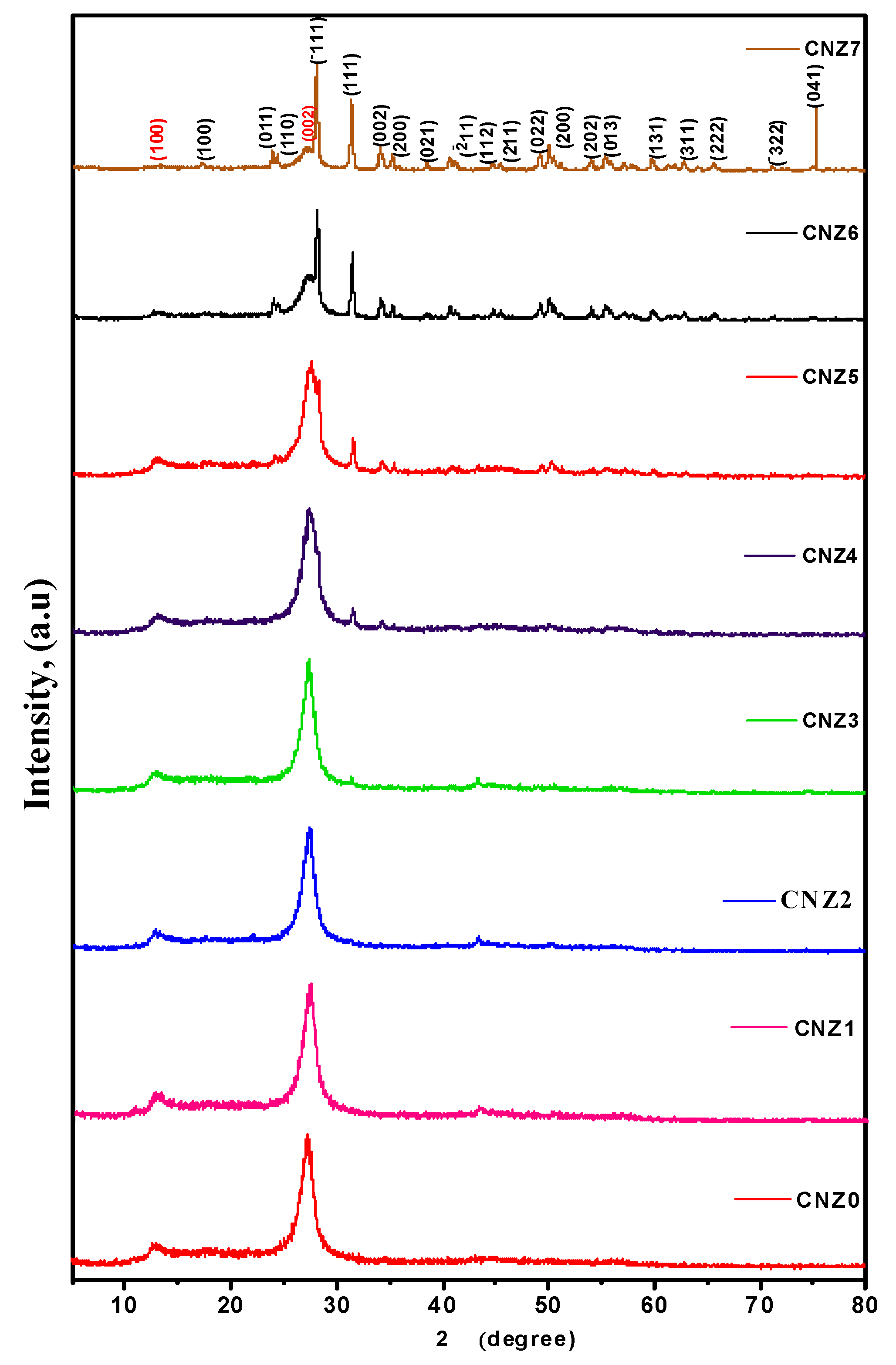
2.1. XRD Analysis

X-ray diffraction (XRD) analysis is a crucial technique in inspecting the heterojunctions and phase structures of pristine materials. Illustrated in Figure 1 are the XRD spectra obtained from the g-CN nanosheet samples. This layer contains an aromatic component, sp2, displaying a hybridized three-s-triazine structure [41]. Concurrently, the (002) planes of the graphitic carbon nitride phase of the hexagonal crystal for [JCPDS 87-1526] resulted in two diffraction peaks, specifically at 12.8° and 27.3° for g-CN [42].
Notably, the (002) diffraction peak appears relatively weaker for the synthesized g-CN nanosheet and particle. This observation considers the surface area ratio between two distinct peaks and suggests a decrease in the layered structural elements. The diffraction peak of the (002) plane in the g-CN nanosheet undergoes a slight shift from 27.3° to 28.1°, signifying the thermal exfoliation of the g-CN [43].
Figure 1 displays the XRD diffraction peaks of ZrO2 with varied morphologies. According to the findings (JCPDS 01-078-0047), the produced ZrO2 exhibits monoclinic phases. Diffraction peaks occur at 2θ:17.28°, 23.96°, 24.42°, 28.15°, 31.4°, 34.16°, 35.30°, 38.52°, 44.82°, 49.22°, 50°, 54.02°, 55.34°, 59.76°, 62.82°, 65.68°, 71.06°, and 75.20°, corresponding to the monoclinic phase, and which are conveniently assigned to the planes of (100), (011), (110), (−111), (111), (002), (200), (021), (−211), (112), (211), (022), (200), (202), (013), (131), (311), (222), (−322), and (041) [44,45] respectively. It has also been found, in Figure 1, that the g-CN diffraction peaks rise while the ZrO2 content decreases in the synthesized samples.
To determine the average crystallite size, lattice strain, and dislocation density of the samples, Debye–Scherrer’s formula was applied [46]:
D = k   λ β   c o s θ  
where D is the size of the crystallite, β is the full width at half maximum (FWHM), λ is the wavelength, and lattice strain (ε) was determined [46]:
ε = β   c o s θ 4
while dislocation density (δ) was obtained through the following:
δ = 1 D 2
Table 1 lists the average crystallite size values derived, the lattice strain determined from the XRD spectra, and the dislocation for all the manufactured samples. Additionally, the FWHM is β, and the diffraction peak angle is θ , respectively. The lattice strain, dislocation, and average crystallite size values computed using the XRD spectra for the first phase was determined to be between 10.011 and 17.029 nm, whereas the average crystallite size for the ZrO2 phase was between 7.422 and 33.167 nm. It should be observed that the size of the crystallites tends to grow as the strain decreases. Equation (4) demonstrates that the lattice strain value relies on both β and cosθ, and are given in Table 1, together with the mean values of the lattice strain for each phase obtained. The range of the g-C3N4 phase’s lattice strain means was 2.683 × 10⁻³ to 3.456 × 10⁻³. At the same time, for the ZrO2 phase, this varied from 1.84 × 10⁻³ to 4.670 × 10⁻⁴. As stated in Equation (5), the dislocation density (δ) can also be used to determine crystallinity. The g-C3N4 phase varied between 6.511 and 10.615 × 10⁻³ and between 1.045 and 8.816 × 10⁻³ for the ZrO2 phase. It was indicating that linked ZrO2 levels were rising. The XRD data generally supported the creation of the gC3N4@ZrO2 heterojunction photocatalyst using the one-pot synthesis method.

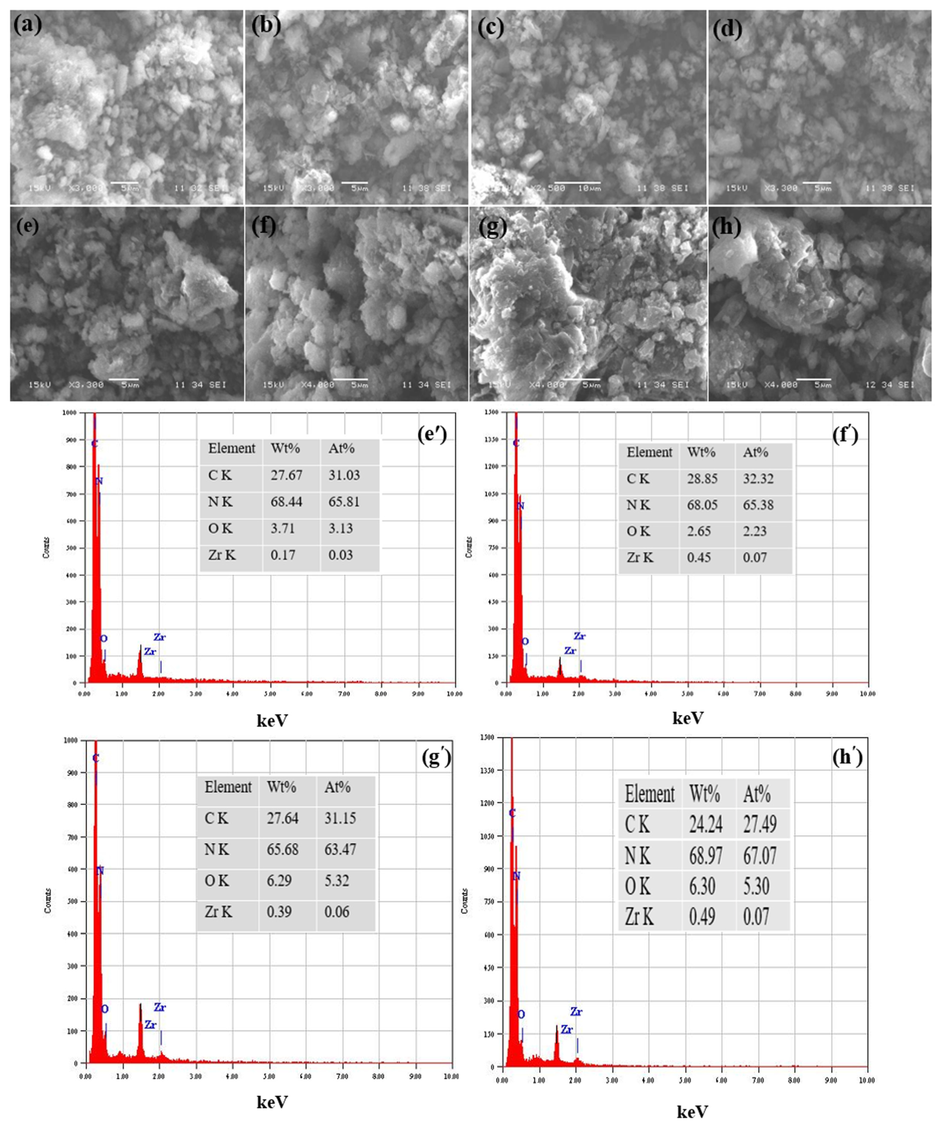
2.2. Morphological Analysis
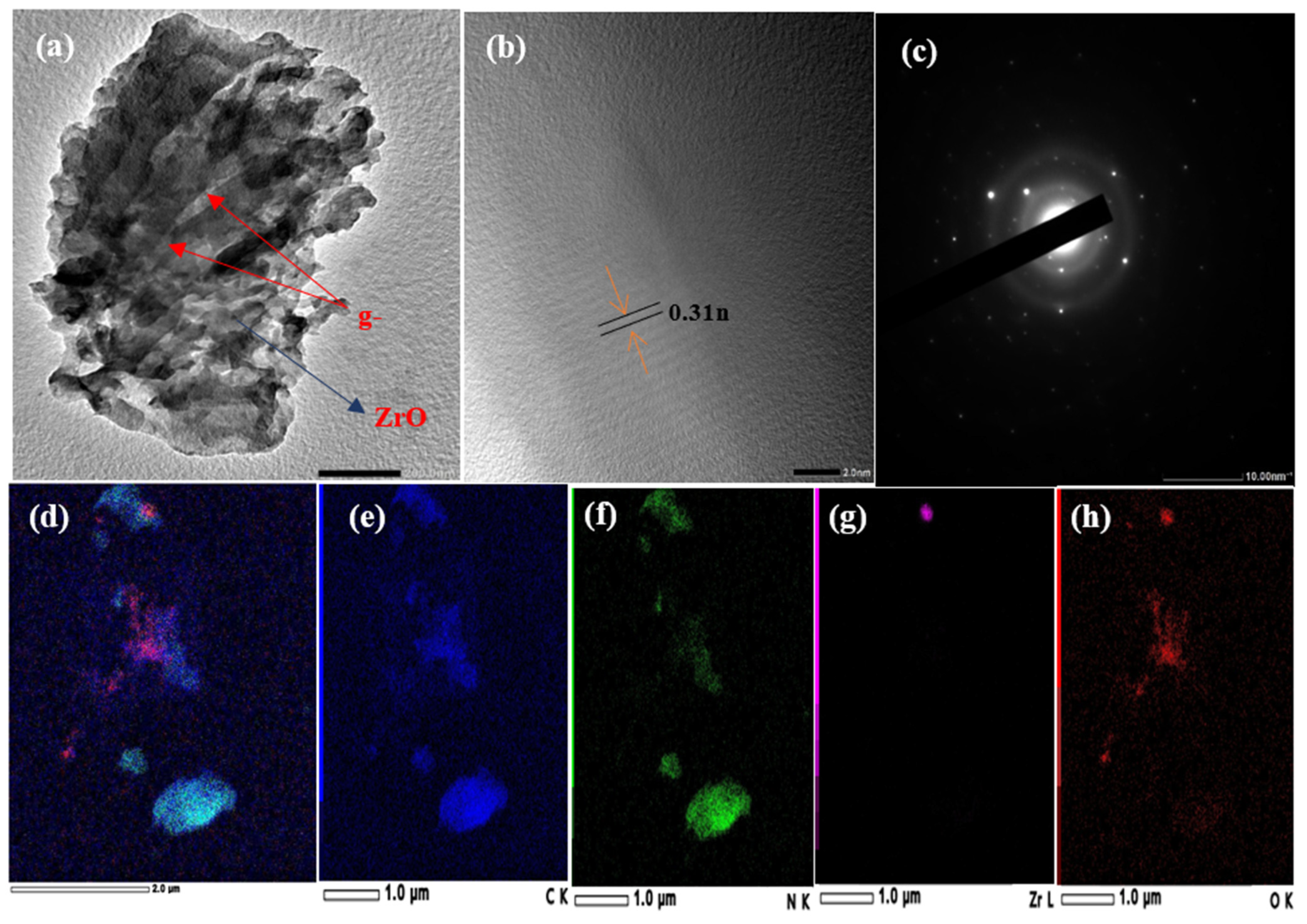
The scanning electron microscopy (SEM) analysis was meticulously conducted on the g-CN and g-CNZ nanocomposite samples to discern the surface topography and underlying microstructure. Figure 2a distinctly illustrates the lamellar framework and multiplex aggregation phenomena characteristic of pure g-CN [47]. The strikingly divergent morphologies of the two materials are readily distinguishable under the lens of the scanning electron microscope, facilitating differentiation. Accumulated research has postulated that this unique structure could potentially provide a wealth of active sites, augment the migration of the resultant carriers, facilitate the optimal catalyst selection process, and stimulate the evolution of a photocatalyst heterojunction [48]. As revealed in Figure 2b–h, the irregular mass is an assembly of ZrO2 enveloped by a layer of flaky g-C3N4, signifying that the two constituents are meticulously compounded. The particulate dimensions fall within a range of 100 to 260 nm. The distinctive morphologies of the ZrO2 and g-CN enable the straightforward identification of the two semiconductors in the SEM images. It is observable within the composites that the ZrO2 nanoparticles are enrobed on the g-CN surface, corroborating that the two components are intimately combined [48]. The composite’s energy-dispersive X-ray spectroscopy (EDX) findings are shown in Figure 2. The evenly distributed constituents—namely, C, N, Zr, and O—illustrated in Figure 2e′–h′, bolster the presence of the dopant and thus corroborate the successful synthesis of the composite. Following aggregation, the photocatalysts’ morphologies exhibit a uniform dispersion, indicative of the crystalline ZrO2’s effect inherent in the composite photocatalyst, a conclusion that aligns with the XRD outcomes [49].

2.3. HRTEM Analysis

Figure 3 shows the TEM images of the g-CNZ6 nanocomposite. g-C3N4 is shown as a nanosheet with its heterojunctions. As observed in Figure 3a, g-C3N4 exhibits a large and ultrathin wrinkled nanosheet morphology, which is because of the thermal exfoliation of the CN bulk, and the ZrO2 irregular spherical nanostructure is deposited on the g-C3N4 nanosheet to form g-C3N4@ ZrO2 heterojunctions. The particle diameters of 6–8 nm of the ZrO2 nanostructures in the heterojunction samples are also shown. The surface energy affected by the size and shape of the ZrO2 nanostructures can be influenced by their amount and distribution over the g-C3N4 nanosheet. Close interfacial contact between g-C3N4 nanosheet and ZrO2 nanoparticle is expected to improve the transfer and separation of the excited eCB—h+VB pairs and increase the heterojunction photocatalytic performance [48]. Compared with the non-crystalline structure of g-C3N4, the g-CNZ nanocomposite displayed crystallinity. The ZrO2 structure, shown in Figure 3b, with an interplanar spacing of 0.31 nm, was related to the (−111) planes of the ZrO2 phases, as shown in Figure 3b [49]. In the SAED patterns in Figure 3c, the bright spots confirm the high crystallinity of the sample. The well-resolved crystalline rings in the SAED correspond to the (111) and (−111) planes of the monoclinic zirconia nanoparticles, which match well with the observed XRD patterns. Figure 3d–h shows the mapping of all the elements in the g-CNZ6 nanocomposite. The photocatalyst confirms that the composite g-CNZ6 samples contain C, N, Zr, and O elements.

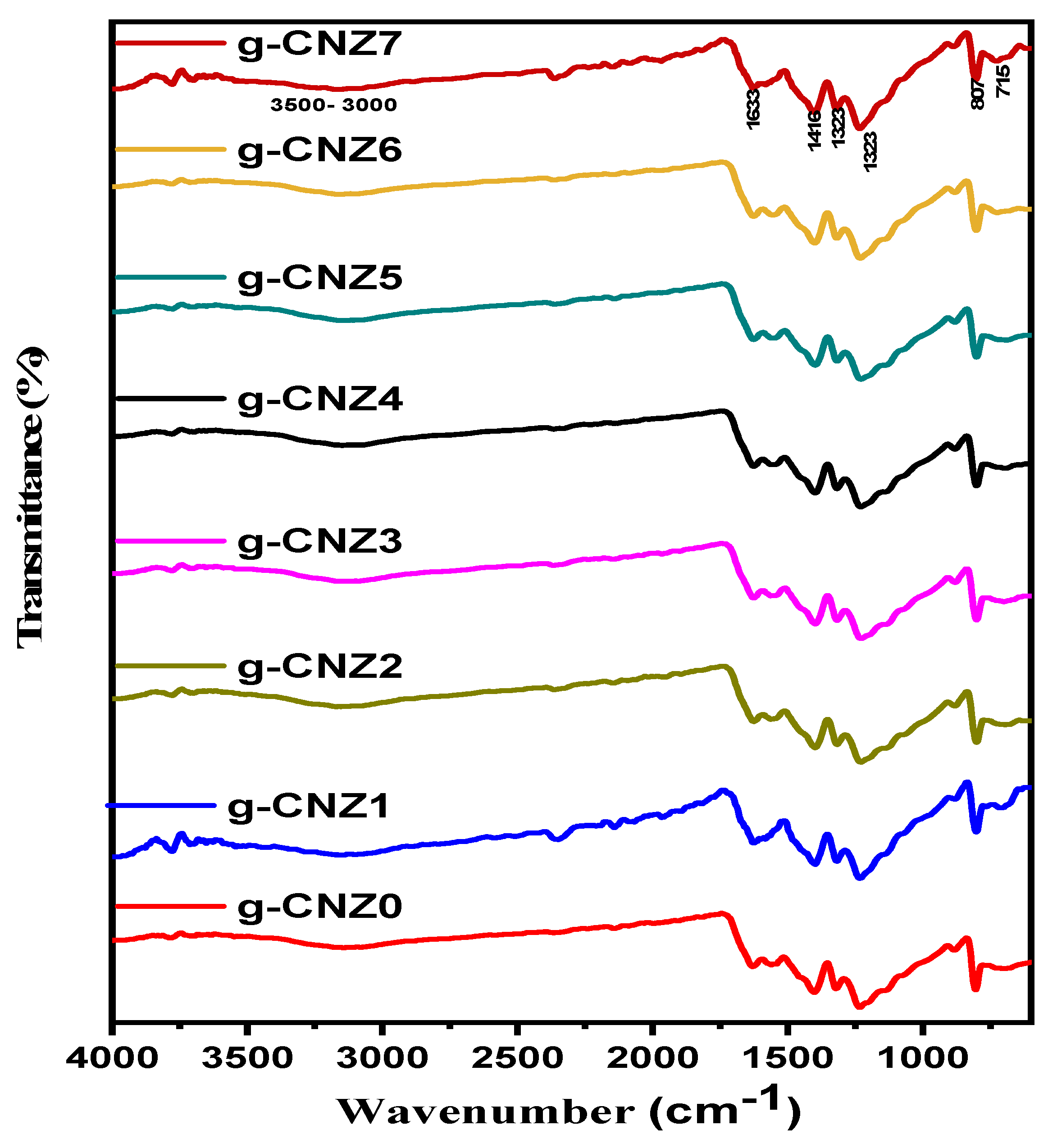
2.4. Functional Group Analysis

Figure 4 delineates the pure g-C3N4 and g-C3N4@ZrO2 nanocomposites with their associated FT-IR spectra. Due to the –NH stretching frequencies and incomplete condensation of the NH2 group, pure g-C3N4 distinctly displays a peak within the range of 3500 to 3000 cm−1 [32]. The vibrational peaks at 1230, 1323, and 1416 cm−1 are attributable to the stretching vibrations of the aromatic C–N, whereas the peak at 1633 cm−1 indicates the tensile stretching of the C=N [50,51]. The characteristic triazine structural unit manifests a notable vibrational peak at 807 cm−1 [52]. The characteristic ZrO2 peaks at 715 cm−1 are predominantly due to the Zr–O molecular chain vibration [53]. Both the g-C3N4 and ZrO2 distinctive peaks are discernible in the g-C3N4@ZrO2 nanocomposite spectrum, thus corroborating the successful ZrO2 incorporation into g-C3N4. Additionally, as the quantity of ZrO2 doping increases, the prominence of the ZrO2 absorption peak is enhanced, as the XRD data substantiates.

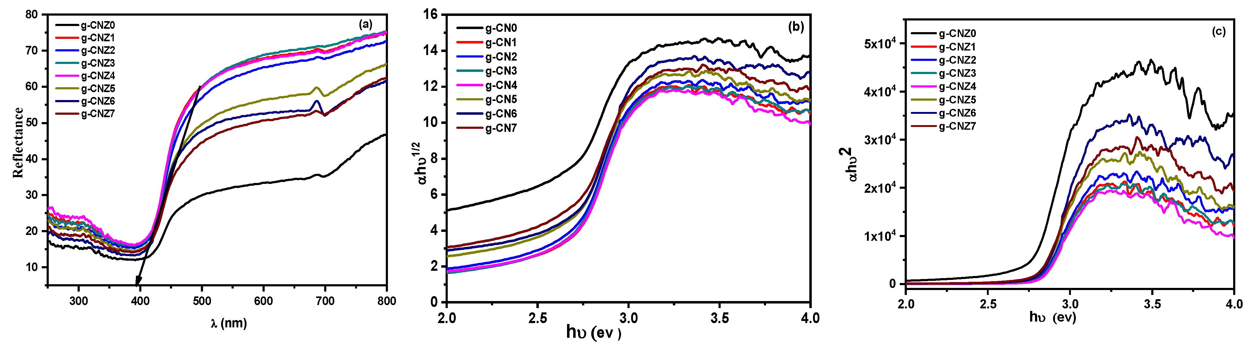
2.5. Optical Analysis

Using the UV–Vis diffuse reflectance spectroscopy (DRS) method, the capacity of the photocatalysts to absorb light and generate charge carriers in the g-CN and g-CNZ nanocomposites is assessed. Using the cut line approach, the absorption wavelength threshold is established by creating a tangent and intersection with the abscissa. The raw g-CN absorption edge, visible in Figure 5a, is like that of paper and has a wavelength of about 407 nm. It is located within the visual zone [54]. The percentage reflectance increases with rising ZrO2 concentrations at extremely low concentrations, peaking for the g-CNZ3 sample. After that, a definite diminishing trend is seen with increasing ZrO2 concentrations. The absorption wavelength threshold values for the g-CNZ3 sample are red-shifted and have a maximum band edge of 388 nm, whereas the pure g-C3N4 can absorb light up to a maximum wavelength of 407 nm. The reflectance rises with rising ZrO2 concentrations at extremely low concentrations, peaking for the g-CNZ3 sample. After that, an obvious decrease is seen with increasing ZrO2 concentrations. The highest band edge for the g-CNZ3 sample is 388 nm, whereas the pure g-C3N4 can absorb light up to a maximum wavelength of 407 nm. The values of the absorption wavelength threshold are red-shifted within the range of (388–407 nm). Therefore, adding ZrO2 makes g-C3N4’s ability to absorb visible light more effective. The interaction of ZrO2 with g-C3N4 may lead to chemical bonds being formed between the two semiconductors, improving the optical characteristics and producing charge carriers [55]. From the Tauc’s relation provided in the following Equation (6), the calculated band gap E g of the samples was determined [56]:
( α h ν ) 1 / n = A ( h ν E g )
where , α, A, and Eg are defined as the incident light frequency, the absorption coefficient, a constant parameter, and the band gap energy, respectively. Also, the value of n depends on the optical transition type in a semiconductor, which is determined to be ½ and 2 for the CNZ0 and g-CNZ nanocomposites, respectively [56,57,58]. The n value is ½ for a direct bandgap semiconductor, while for the indirect bandgap materials, the n value will equal 2. The (αhν)2 and (αhν)1/2 vs. () graphs were plotted for the direct and indirect bandgap semiconductor, as shown in Figure 5b,c. In the graphs, a straight line is fitted for the straight segment. The straight line to the E axis gives the band gap values. e.g., the values were found to be decreased. The rise in the carrier concentration leads to the development of certain chemical bonds between the g-CNZ0 and g-CNZ, which is expected to cause a decrease in the band gap and improve the optical characteristics. Table 2 lists all the estimated values for the direct and indirect bandgaps, respectively.

2.6. Photocatalytic Performance

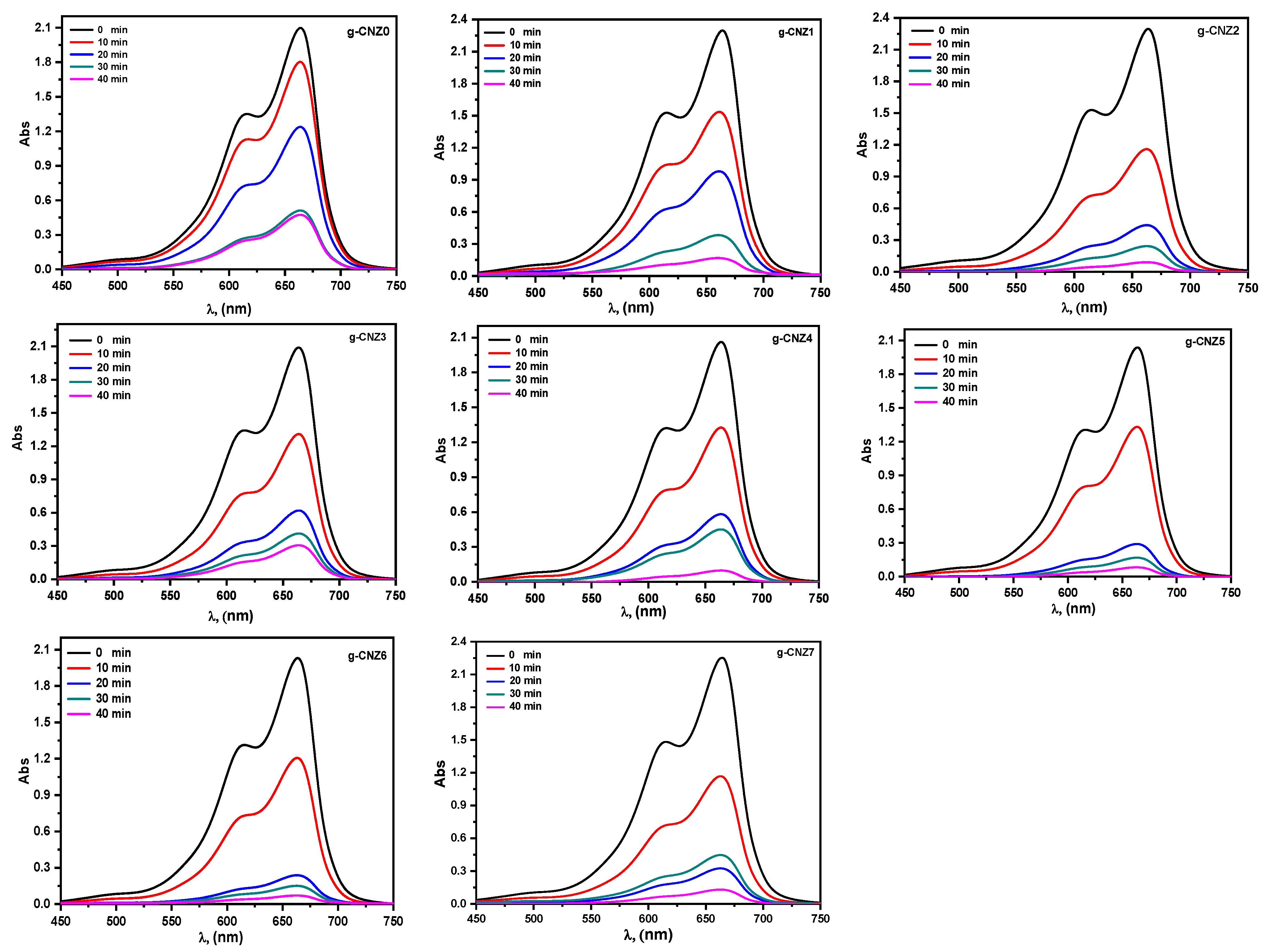
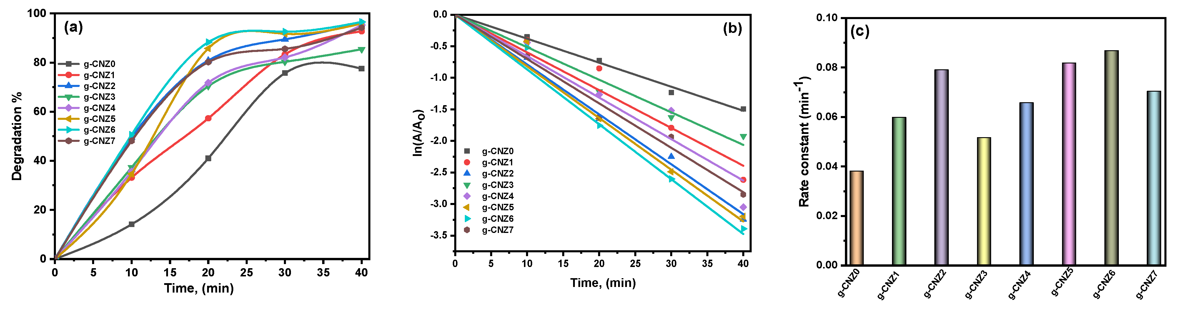
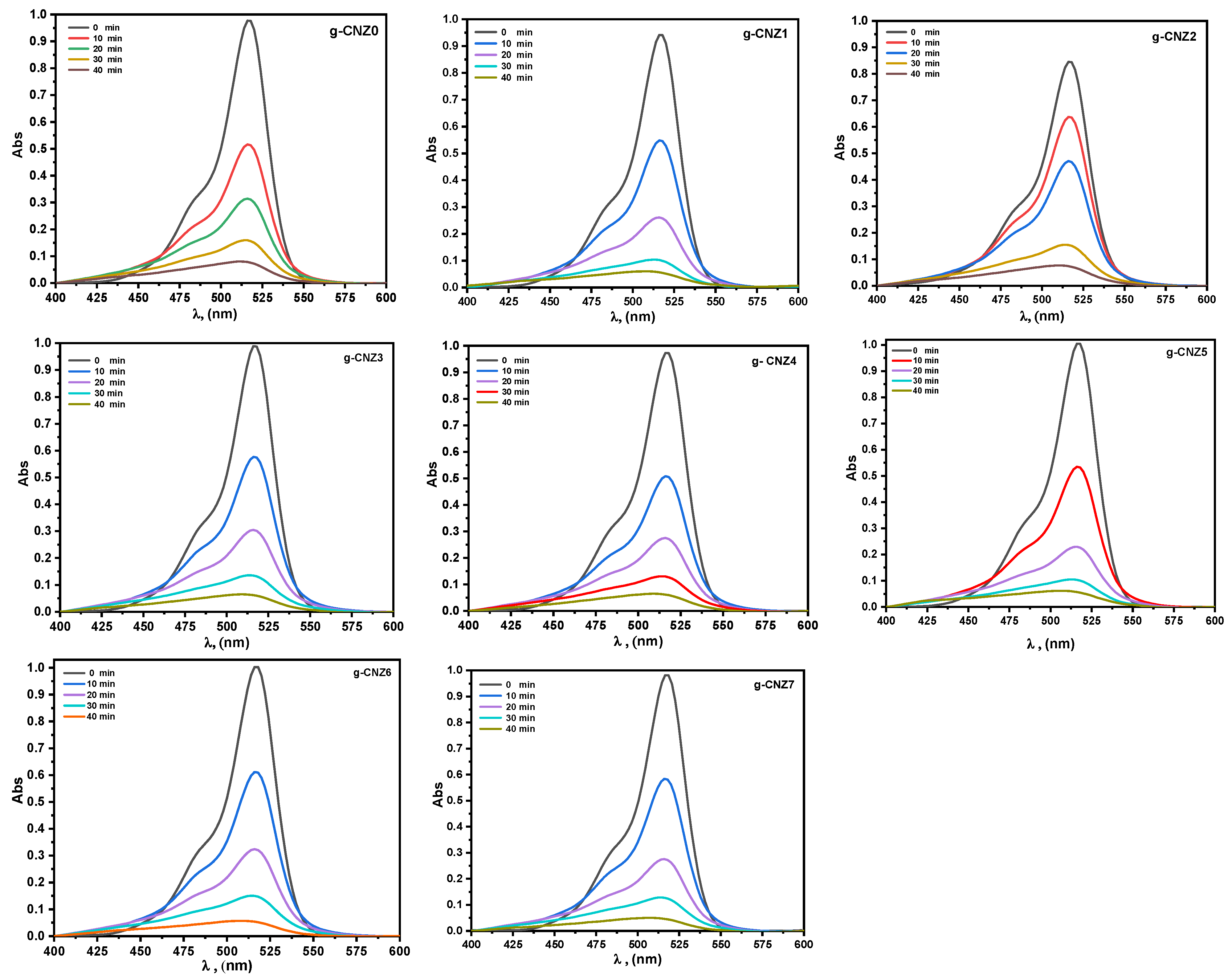
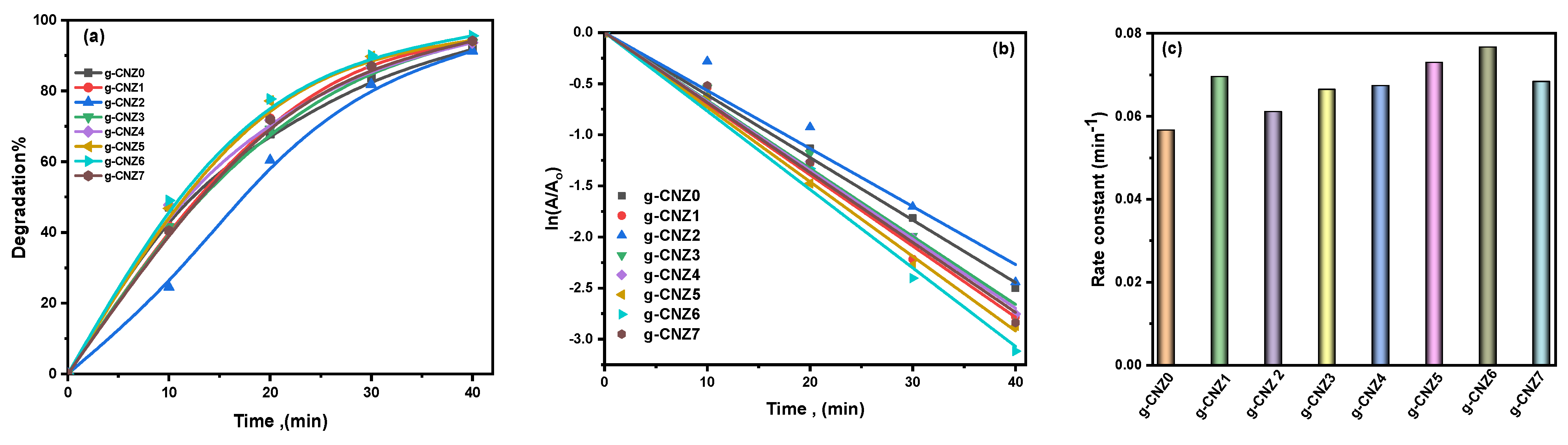
2.6.1. Photocatalytic Degradation of MB and EY Dyes

Methylene Blue (MB) and eosine yellow (EY), acting as model pollutants, were engaged to evaluate the photocatalytic performance under simulated UVc light irradiation. A thoroughly dark environment was ensured to conduct the adsorption assays of the MB and EY dyes. Approximately half an hour later, a dynamic equilibrium state was achieved, satisfying the stability prerequisites for the adsorption/desorption processes of the tested catalyst specimens.
Figure 6 delineates the absorption intensity recorded at 663 nm, further augmented by the absorption spectra of the MB dye interacting with diverse catalysts throughout the photocatalytic response. Once a photocatalyst is incorporated into the catalytic system, a marked reduction in the MB concentration is observed, which intensifies in direct proportion to the prolonged duration of the catalytic process, as depicted in Figure 6. The efficacy of the MB dye degradation, observed over 40 min of photo-irradiation, is presented in Figure 7a. Table 3 exhibits the perceptible degradation of MB as a consequence of the reaction with the g-CNZ nanocomposites. Following the application of Equation (1), the MB degradation efficiency was determined to be 77.5% and 96.5% for the g-CNZ0 and g-CNZ6 nanocomposites, respectively. A substantial enhancement in the photodegradation of the photocatalyst may have been facilitated by the introduction of 0.5 g of ZrO2 nanoparticles onto the g-CN sheets. This enhancement can be attributed to a robust interfacial interaction, expedited charge mobility, a heightened propensity for charge carrier segregation, and a reduced band gap compared to the g-CNZ0 and g-CNZ6 photocatalysts. Photodegradation rate constants, represented by Equation (2) as per [59], were employed to deduce the photodegradation rate constants. The pure g-CNZ0 displayed a degradation rate of 0.035 min−1. Integrating g-C3N4 with ZrO2 resulted in a remarkable augmentation of the electron–hole separation efficiency and UV light absorption capacity. A concurrent increase in the ZrO2 compounding quantity led to an escalated degradation rate of 0.088 min−1 for the g-CNZ6 nanocomposites, thereby outperforming the rate of the pure g-C3N4 by a factor of 2.5.
As shown in Figure 8, the absorption spectra of the EY dye with different catalysts during the photocatalytic reaction for the experiment showed an absorption intensity at 520 nm. The EY was used as color pollution, and the photocatalytic performance of the as-prepared catalysts was evaluated. Where deterioration was placed 40 min after photoirradiation, the g-CNZ nanocomposite-enhanced photocatalytic performance is demonstrated by the high degradation efficiency and degradation rate constant (k) values in Table 3. As shown in Figure 9a–c, the degradation efficiency of the g-CNZ6 nanocomposite within 40 min of light irradiation is up to 95.6%, with a high degradation rate constant (0.0767 min−1).

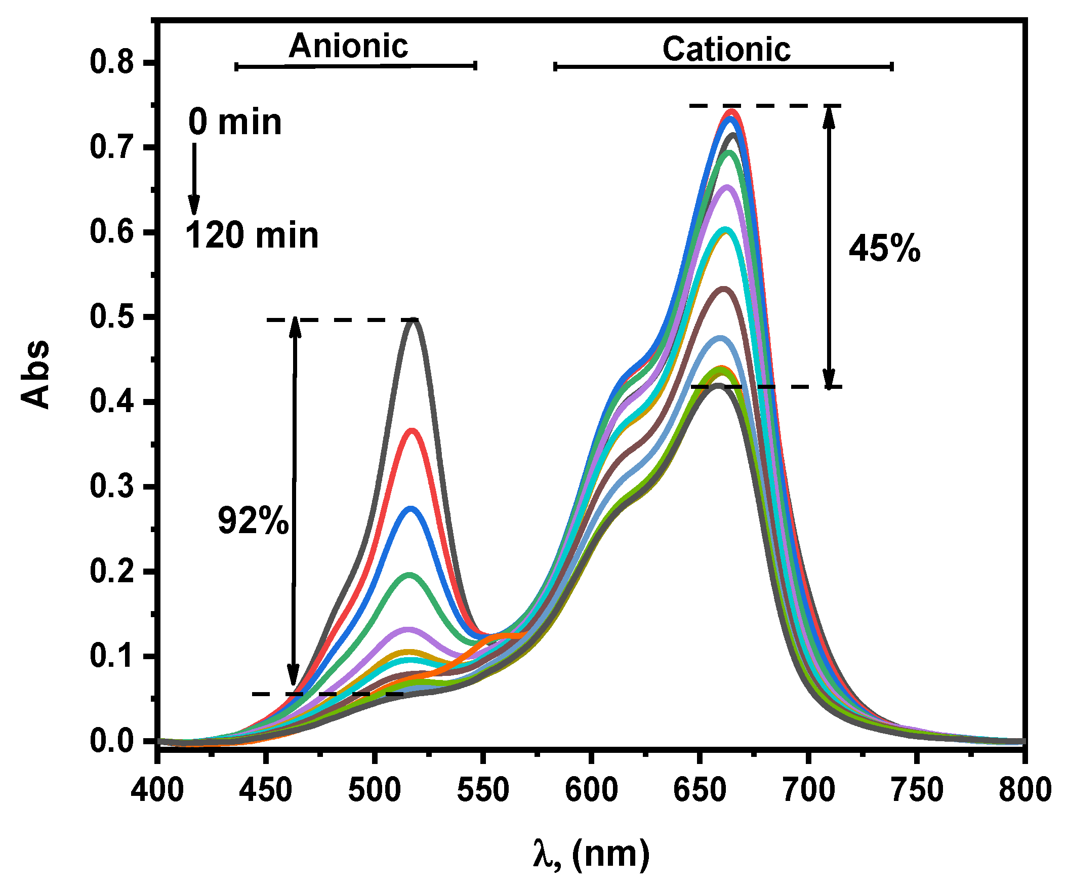
2.6.2. Photodegradation of Mixed Dye

Combining two organic dyes (MB and EY) made it possible to imitate the appearance of real water contamination. The only variation between the experimental setup and the setup for the individual contaminants was the extended adsorption–desorption duration of 30 min. The photocatalyst was dissolved in 200 mL of a solution containing 10 ppm of the MB and EY dye and 0.01 g of the photocatalyst. The results of the evaluation of the g-CNZ6 photocatalyst’s photocatalytic performance for the mixed pollutants are displayed in Figure 10. By observing the UV–vis maximum absorbance peaks of MB and EY at 664 nm and 518 nm, respectively, the photocatalytic performance of the g-CNZ6 nanocomposite towards the matrix of the pollutant was assessed. As shown in Figure 10. their maximum absorbance peaks diminish as the UVc light exposure time increases. At 120 min, photocatalytic rates of above 45% for MB and above 92% for EY were attained. Compared to other cationic dye pollutants (see Table 4), the g-CNZ6 nanocomposite was more effective at removing anionic dyes. According to the above results, our g-CNZ6 photocatalyst can be used in actual wastewater samples even if the better removal efficiency of those pollutants was only attained after a longer irradiation time.

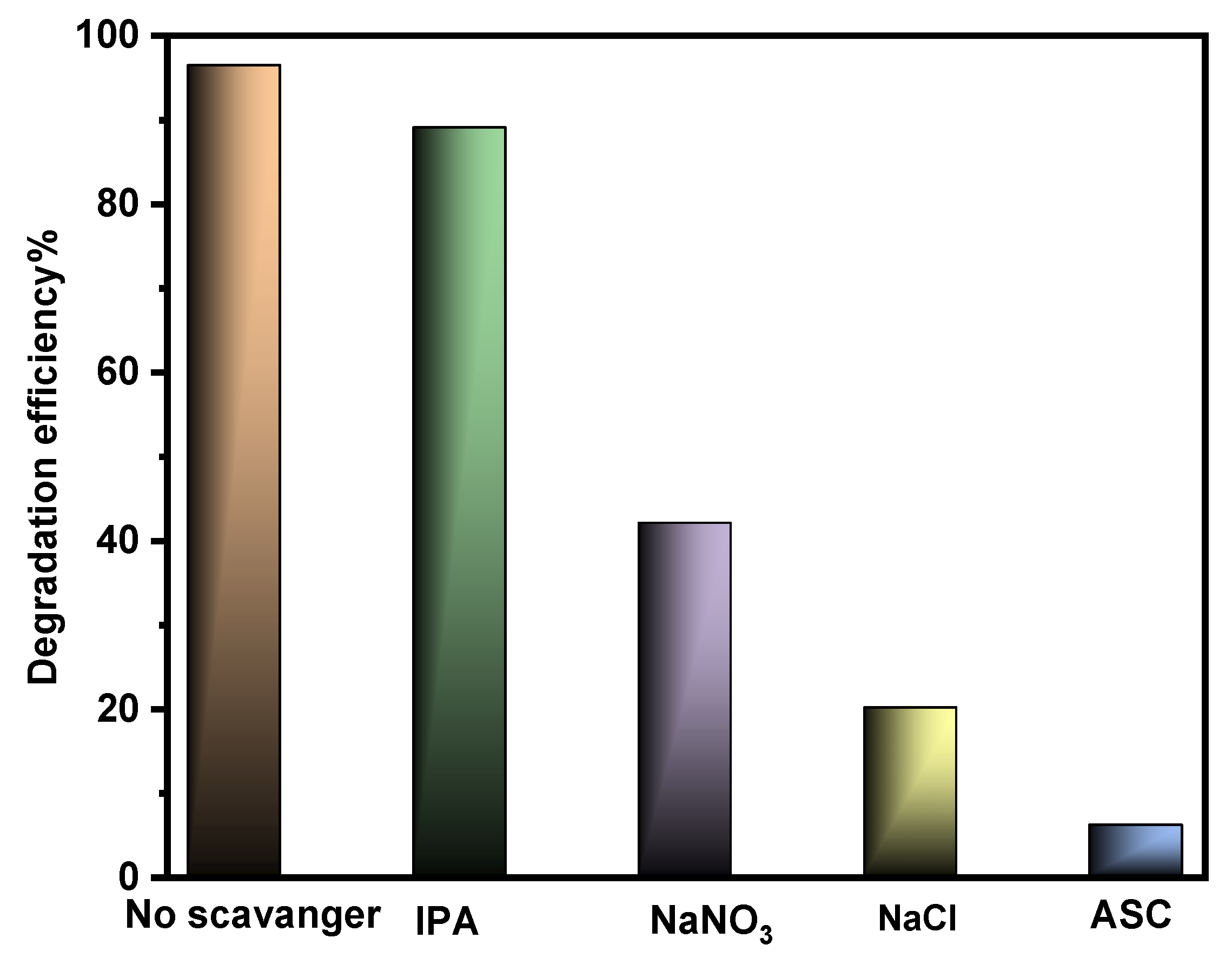
2.6.3. Reactive Species Involved in Photodegradation of MB Dye by g-CNZ6 Nanocomposites

To further understand the g-CNZ6 nanocomposite’s photocatalytic process, free radical capture studies were also conducted. As indicated in Figure 11, four scavengers were added to the pollutant solution before the photocatalytic experiment: isopropyl alcohol (IPA: .OH), sodium chloride (NaCl: h+), ascorbic acid (ASC: O2.), and sodium nitrate (NaNO3: e). The amount of MB degradation was not significantly impacted by ascorbic acid (ASC: O2. scavenger). Since sodium chloride (NaCl) is a h+ scavenger, the degradation percentage dramatically decreases when it is introduced, going from 96.5 % to 20 %. The degradation percentage fell to 10% when ascorbic acid (ASC: O2. scavenger) was present. This implies that h+ and O2. are two important reactive species in the photodegradation of MB by the g-CNZ6 nanocomposites.

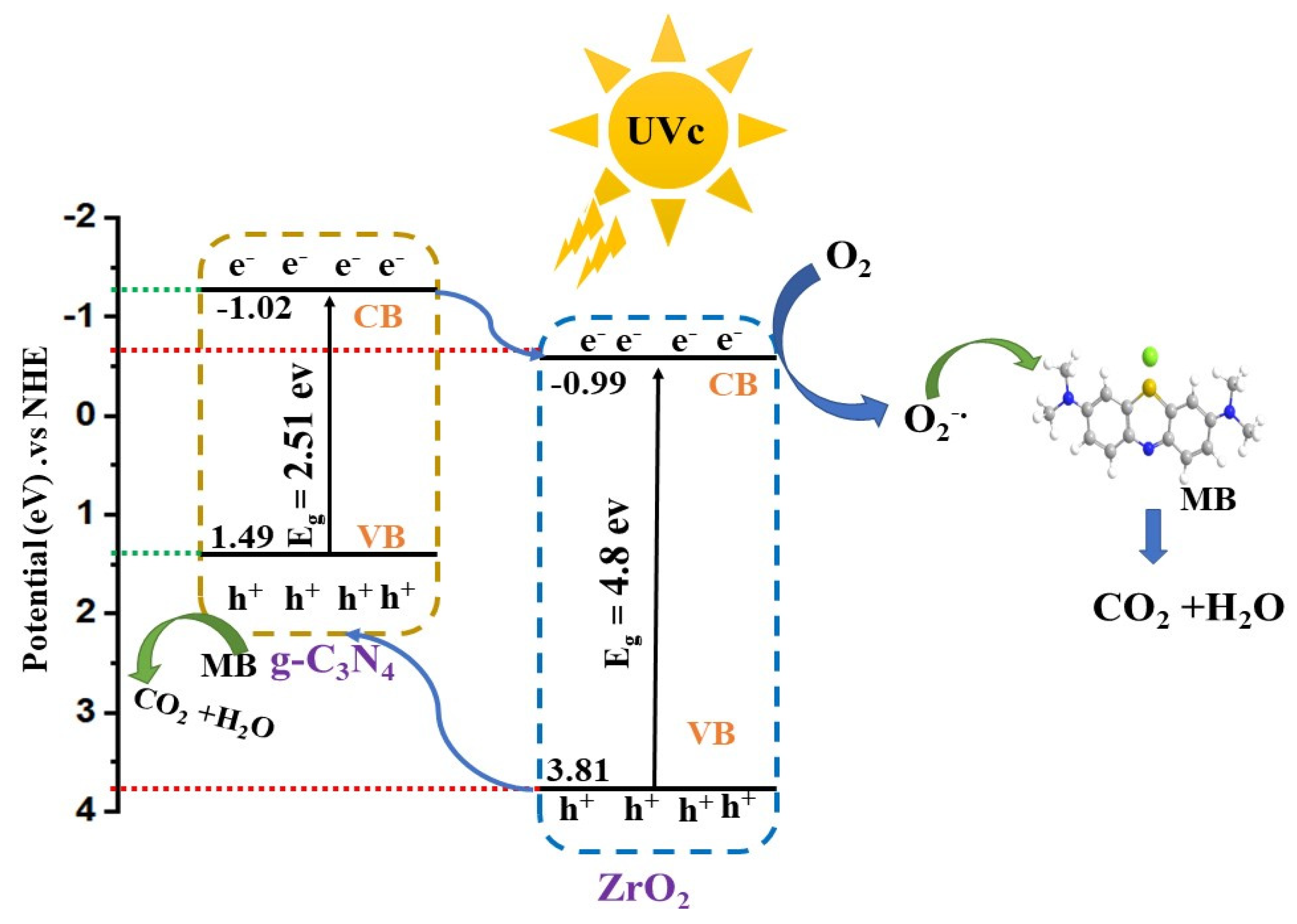
2.6.4. Possible Mechanistic Pathway for Degradation of MB Dye

The following formula describes how the active species in the chemical process in which the semiconductors VB and CB are involved are different [65,66]:
E C B = X E 0 0.5 E g
E V B = E C B + E g
The Eg is the band gap, X is the absolute electronegativity, and the values of g-C3N4 and ZrO2 for X are 4.73 eV and 5.91 eV, respectively. E0 is a constant, regarding the standard H electrode with a value of 4.5 eV [67,68,69]. As a result, the predicted E C B values for the CN nanosheet and ZrO2 nanoparticle are −1.02 and −0.99 eV, respectively. Additionally, the E V B of the samples of the CN nanosheets and ZrO2 nanoparticles is +1.49 and +3.81 eV, respectively. Figure 12 delineates the anticipated method for Methylene Blue (MB) dye degradation by applying a g-CNZ6 nanocomposite under ultraviolet C (UVc) light irradiation. The underpinning of this mechanism is derived from valence band (VB) and conduction band (CB) potentials, extrapolated from diffuse reflectance spectroscopy (DRS) analysis in conjunction with the results from active species experimentation.
The narrow bandgap of pure graphitic carbon nitride (g-C3N4) triggers the generation of electron–conduction band (eCB) and hole–valence band (h+VB) pairs upon exposure to UVc light, a characteristic of individual semiconductors. However, the subsequent rapid recombination of these pairs results in limited photocatalytic activity in pure g-C3N4, attributable to its relatively small bandgap (2.51 eV). Conversely, the large bandgap of pure ZrO2 nanoparticles, estimated at 4.8 eV, inhibits its excitation under UVc light exposure [64]. Consequently, when UVc light is incident on the g-CNZ nanocomposite surface, the valence band (VB) electrons in both semiconductor constituents (g-C3N4 and ZrO2) are instantaneously excited to their respective conduction bands (CBs), leaving behind holes in the VB. The disparity in CB edge potentials between the two materials, with g-C3N4 exhibiting a more negative potential than ZrO2, facilitates the migration of photoexcited electrons from the CB of g-C3N4 to the CB of ZrO2. The resultant electrons reside at the CB of ZrO2, instigating interactions with surface oxygen to form superoxide radicals (O2.), which subsequently interact with MB. Simultaneously, photogenerated holes at the VB of ZrO2 migrate to the VB of g-C3N4 due to the higher VB potential of ZrO2 than g-C3N4. Consequently, these newly formed holes remain in the VB of g-C3N4, where they instigate their reactions with MB. The formation of a type II heterojunction significantly decreases the recombination rate while promoting the separation of photoinduced electrons and holes at the interface between g-C3N4 and ZrO2. The photocarriers at the g-C3N4@ ZrO2 interfaces still maintain the Z-scheme transfer mechanism, like in the case of bare photocatalysis. More interestingly, under the action of the polarization field, the bulk photoelectrons of g-C3N4 and ZrO2 are driven to Z-scheme transfer [65]. The efficiency of the charge transport and separation of electron–hole pairs is contingent on the interaction between ZrO2 and g-C3N4. An excess of ZrO2 can accumulate on the g-C3N4 layer, diminishing the interaction between the two materials and thus compromising the charge separation efficiency. As such, an optimal ZrO2 concentration is deemed crucial. The anticipated mechanism for the degradation of MB by the g-CNZ6 nanocomposite, as represented in Equations (9)–(13), can be described as follows:
g - CNZ 6 + h ν     g - CNZ 6   ( h + V B   +   e C B )
e + O2 → O2
2e + 2H+ + O2 → H2O2
H2O2 + O2.OH + OH + O2
(O2+ h+) + MB → CO2 +H2O

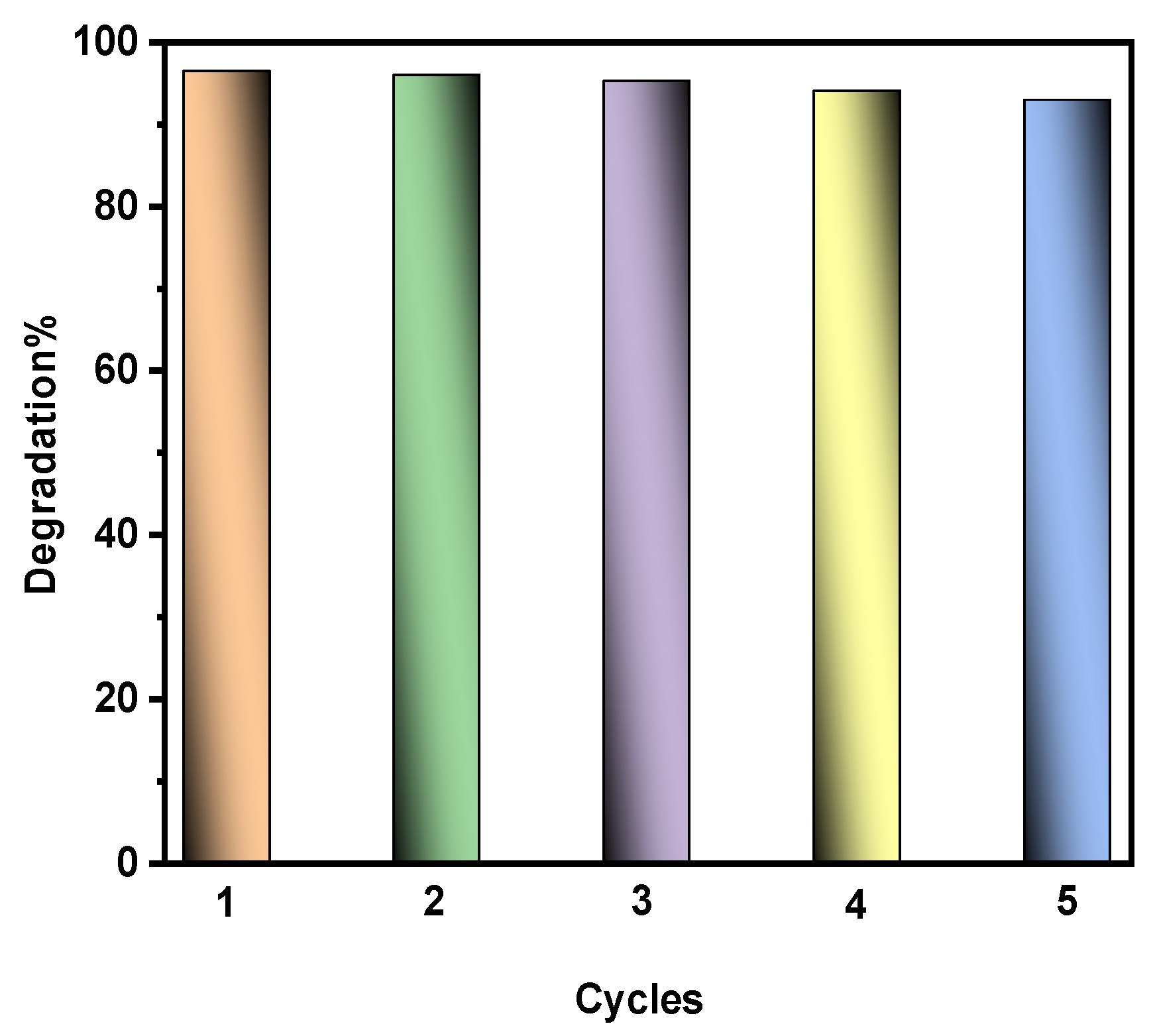
2.6.5. Stability and Recycling

Repeated assessments were executed on M) degradation, extending up to the fifth cycle to validate the scalability of the synthesized g-CNZ6 nanocomposite. Following each cycle, the photocatalyst was retrieved through centrifugation, rinsed with distilled water, and dried in an oven set at a temperature of 80 °C. Figure 13 illustrates a marginal reduction in the photocatalytic efficacy of the g-CNZ6 nanocomposite towards MB photodegradation. However, despite this slight decrement in performance, it was demonstrated that the g-CNZ6 nanocomposite maintains considerable photocatalytic activity over multiple iterations. This observed resilience solidifies g-CNZ6’s position as a competent photocatalyst. The composite can be recycled and reused multiple times while demonstrating substantial activity in a photocatalytic reaction, reinforcing its potential for sustained utilization.

3. Experimental Section

3.1. Materials

Zirconium oxychloride (ZrOCl2·8H2O) was procured from Alpha Chem (Darmstadt, Germany). Urea, thiourea, methylene blue (MB), and eosin yellow (EY) were obtained from Merck (Darmstadt, Germany). Double distilled water (DDW) was employed in the preparation of samples.

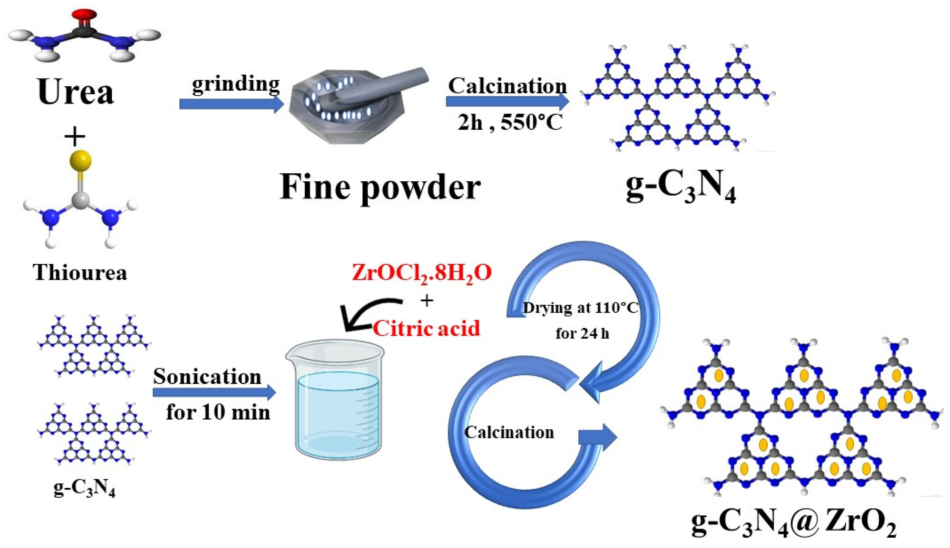
3.2. Preparation of g-C3N4@ZrO2

Porous graphitic carbon nitride (g-CN) was prepared via thermal polycondensation of urea. A predefined amount of 6 g from urea and thiourea was finely ground and placed in a closed crucible and subjected to a controlled heating regimen at a rate of 5 °C/min up to a final temperature of 550 °C, which was maintained for post-cooling to ambient cycles, and the product was finely ground in an agate mortar.
The synthesis of g-C3N4@ZrO2 nanocomposites was conducted following the protocol illustrated in Figure 14. A total of 0.5 g from g-C3N4 was added to 50 mL DDW and placed in an ultrasonic probe for 15 min. A homogenous mixture was created by adding 10 g of Zirconium oxychloride to 10 g of citric acid, into which specific proportions of ZrO2 was added, and was stirred for 30 min to establish homogeneity in the resulting solution. This mixture was subsequently dried at 100 °C for 24 h. The dried composite was then calcinated at 550 °C for 2 h in a muffle furnace and later crushed to a uniform powder. The final composites, bearing different proportions of ZrO2 (0.001, 0.005, 0.01, 0.05, 0.1, 0.5, and 1 g), were designated as g-CNZ0 through g-CNZ7, respectively.

3.3. Characterization Techniques and Devices

X-ray diffraction (XRD) was employed to determine the crystalline structure of the synthesized photocatalysts. Scanning electron microscopy (SEM, model JSM-6360, Tokyo, Japan) operating at 20 kV, supplemented with energy-dispersive X-ray spectroscopy (EDX), was used to probe the surface morphology and elemental composition. The functional chemical bonds were identified from FT-IR Perkin Elme(Waltham, MA, USA) r in the range of 4000 to 400 cm−1 wavenumber. The optical properties were observed using UV–visible DRS (JASCO V-570, Tokyo, Japan).

3.4. Photoreactor Design and Photocatalytic Activity of g-C3N4@ZrO2 Nanocomposites for Photodegradation

The photocatalytic performance of the synthesized g-C3N4@ZrO2 nanocomposites was measured under UVC radiation for the model pollutant using a wooden photoreactor at room temperature, designed by I.S. Yahia and his group at NLEBA/ASU/Egypt; more details about the photoreactor are mentioned in Hussien et al. [70]. The dyes methylene blue (MB) and eosin yellow (EY) were employed as contaminants for this assessment. The structure, chemical formula and type are shown in Table 5. A total of 0.01 g of each composite was dispersed in a 200 mL solution containing either dye at a concentration of 10 ppm, and the mixture was subjected to dark conditions for approximately 30 min to attain adsorption–desorption equilibrium. After this period, samples were extracted and centrifuged at 3000 rpm for 10 min, and the residual mixture was re-illuminated using UVc lamps. Photocatalytic activity was quantified at intervals of 10 min during irradiation, and photodegradation was monitored within the range of 400 to 800 nm using a UV–Vis spectrophotometer (Agilent, Santa Clara, CA, USA). Degradation efficiency and apparent rate constants were calculated using Equations (1) and (2) [71]; the degree of dye degradation, apparent degradation rate constant ( k a p p ) in m i n 1 , and photodegradation efficiency ( P D E % ) were systematically calculated. A o and A denote the dye concentration at the initial time and at a desired time t post-irradiation, respectively.
P D E % = A o A A o × 100 %
ln   ( A A o )   =   K t

4. Conclusions

In this investigation, we have developed an augmented photocatalyst, a g-C3N4@ZrO2 composite, exhibiting an amplified response to direct UVc light exposure, synthesized via a simple pyrolysis process of fabricated g-C3N4@ZrO2 samples, complemented by sonication. Upon exposure to direct UVc radiation, the g-CNZ6 nanocomposite demonstrated superior photocatalytic efficacy in degraded MB, EY, and a mixed dye. Compared to the pure g-C3N4, the degradation efficiency of the g-CNZ6 nanocomposite was remarkably higher, with respective yields of 96.5% and 95.6% for the MB and EY dyes. This significant increase in the photocatalytic performance can be attributed to the synergistic interaction between ZrO2 and g-C3N4, culminating in efficient electron–hole pair separation, a critical driver of photocatalysis. An extensive series of reusability experiments unveiled that the g-CNZ6 nanocomposite maintained its photocatalytic stability and robustness, indicating promising potential for sustainable applications in dye degradation and water treatment.

Author Contributions

Conceptualization, A.T.M., F.F.A.-H., S.M.G., H.Y.Z., M.S.A.H. and I.S.Y.; Methodology, A.T.M., F.F.A.-H., S.M.G., S.H.Z., H.Y.Z. and I.S.Y.; Software, A.T.M., F.F.A.-H., S.M.G., S.H.Z., M.S.A.H. and I.S.Y.; Resources, F.F.A.-H. and S.M.G.; Writing—original draft, A.T.M., F.F.A.-H., S.M.G., S.H.Z., H.Y.Z., M.S.A.H. and I.S.Y.; Writing—review & editing, A.T.M., F.F.A.-H., S.M.G., S.H.Z., H.Y.Z., M.S.A.H. and I.S.Y.; Visualization, A.T.M., F.F.A.-H., S.M.G., S.H.Z., H.Y.Z. and I.S.Y.; Supervision, F.F.A.-H., S.M.G. and I.S.Y.; Project administration, F.F.A.-H., S.M.G. and I.S.Y.; Funding acquisition, F.F.A.-H. and S.M.G. All authors have read and agreed to the published version of the manuscript.

Funding

This research project was funded by the Deanship of Scientific Research, Princess Nourah bint Abdulrahman University, through the program of research project funding after publication, grant NO. 44-PRFA-P-100.

Data Availability Statement

Data are contained within the article.

Conflicts of Interest

The author Ahmed T. Mosleh was employed by the Egyptian Company for Carbon Materials. The remaining authors declare that the research was conducted in the absence of any commercial or financial relationships that could be construed as a potential conflict of interest.

References

  1. Shwetharani, R.; Chandan, H.; Sakar, M.; Balakrishna, G.R.; Reddy, K.R.; Raghu, A.V. Photocatalytic semiconductor thin films for hydrogen production and environmental applications. Int. J. Hydrogen Energy 2020, 45, 18289–18308. [Google Scholar] [CrossRef]
  2. Vickers, N.J. Animal communication: When I am calling you, will you answer too? Curr. Biol. 2017, 27, R713–R715. [Google Scholar] [CrossRef] [PubMed]
  3. Ali, A.; Ahmed, A.; Usman, M.; Raza, T.; Ali, M.S.; Al-Nahari, A.; Liu, C.; Li, D.; Li, C.J.D.; Materials, R. Synthesis of visible light responsive Ce0.2Co0.8Fe2O4/g-C3N4 composites for efficient photocatalytic degradation of rhodamine B. Diam. Relat. Mater. 2023, 133, 109721. [Google Scholar] [CrossRef]
  4. Li, L.; Sun, X.; Xian, T.; Gao, H.; Wang, S.; Yi, Z.; Wu, X.; Yang, H. Template-free synthesis of Bi2O2C3 hierarchical nanotubes self-assembled from ordered nanoplates for promising photocatalytic applications. Phys. Chem. Chem. Phys. 2022, 24, 8279–8295. [Google Scholar] [CrossRef] [PubMed]
  5. Cheng, T.; Gao, H.; Liu, G.; Pu, Z.; Wang, S.; Yi, Z.; Wu, X.; Yang, H.J.C.; Physicochemical, S.A.; Aspects, E. Preparation of core–shell heterojunction photocatalysts by coating CdS nanoparticles onto Bi4Ti3O12 hierarchical microspheres and their photocatalytic removal of organic pollutants and Cr (VI) ions. Colloids Surf. A Physicochem. Eng. Asp. 2022, 633, 127918. [Google Scholar] [CrossRef]
  6. Saravanan, A.; Kumar, P.S.; Jeevanantham, S.; Karishma, S.; Tajsabreen, B.; Yaashikaa, P.; Reshma, B.J.C. Effective water/wastewater treatment methodologies for toxic pollutants removal: Processes and applications towards sustainable development. Chemosphere 2021, 280, 130595. [Google Scholar] [CrossRef] [PubMed]
  7. Zhang, S.; Li, B.; Wang, X.; Zhao, G.; Hu, B.; Lu, Z.; Wen, T.; Chen, J.; Wang, X. Recent developments of two-dimensional graphene-based composites in visible-light photocatalysis for eliminating persistent organic pollutants from wastewater. Chem. Eng. J. 2020, 390, 124642. [Google Scholar] [CrossRef]
  8. Yang, X.; Zhou, J.; Huo, T.; Lv, Y.; Pan, J.; Chen, L.; Tang, X.; Zhao, Y.; Liu, H.; Gao, Q.; et al. Metabolic insights into the enhanced nitrogen removal of anammox by montmorillonite at reduced temperature. Chem. Eng. J. 2021, 410, 128290. [Google Scholar] [CrossRef]
  9. Lim, J.; Kim, H.; Park, J.; Moon, G.-H.; Vequizo, J.J.M.; Yamakata, A.; Lee, J.; Choi, W. How g-C3N4 works and is different from TiO2 as an environmental photocatalyst: Mechanistic view. Environ. Sci. Technol. 2019, 54, 497–506. [Google Scholar] [CrossRef]
  10. Hoffmann, M.R.; Martin, S.T.; Choi, W.; Bahnemann, D.W. Environmental applications of semiconductor photocatalysis. Chem. Rev. 1995, 95, 69–96. [Google Scholar] [CrossRef]
  11. Habibollahi, Z.; Peyravi, M.; Khalili, S.; Jahanshahi, M. ZnO-based ternary nanocomposite for decolorization of methylene blue by photocatalytic dynamic membrane. Mater. Today Chem. 2022, 23, 100748. [Google Scholar] [CrossRef]
  12. Kazemi, M.; Peyravi, M.; Jahanshahi, M. Multilayer UF membrane assisted by photocatalytic NZVI@ TiO2 nanoparticle for removal and reduction of hexavalent chromium. J. Water Process Eng. 2020, 37, 101183. [Google Scholar] [CrossRef]
  13. Kazemi, M.; Jahanshahi, M.; Peyravi, M. Hexavalent chromium removal by multilayer membrane assisted by photocatalytic couple nanoparticle from both permeate and retentate. J. Hazard. Mater. 2018, 344, 12–22. [Google Scholar] [CrossRef] [PubMed]
  14. Kazemi, M.; Jahanshahi, M.; Peyravi, M. Chitosan-sodium alginate multilayer membrane developed by Fe0@ WO3 nanoparticles: Photocatalytic removal of hexavalent chromium. Carbohydr. Polym. 2018, 198, 164–174. [Google Scholar] [CrossRef]
  15. Zakeritabar, S.F.; Jahanshahi, M.; Peyravi, M.; Akhtari, J. Engineering, Photocatalytic study of nanocomposite membrane modified by CeF3 catalyst for pharmaceutical wastewater treatment. J. Environ. Health Sci. 2020, 18, 1151–1161. [Google Scholar]
  16. Luo, W.; Chen, X.; Wei, Z.; Liu, D.; Yao, W.; Zhu, Y. Three-dimensional network structure assembled by g-C3N4 nanorods for improving visible-light photocatalytic performance. Appl. Catal. B Environ. 2019, 255, 117761. [Google Scholar] [CrossRef]
  17. Chen, Y.; Lu, W.; Shen, H.; Gu, Y.; Xu, T.; Zhu, Z.; Wang, G.; Chen, W. Solar-driven efficient degradation of emerging contaminants by g-C3N4-shielding polyester fiber/TiO2 composites. Appl. Catal. B Environ. 2019, 258, 117960. [Google Scholar] [CrossRef]
  18. Singla, S.; Sharma, S.; Basu, S.; Shetti, N.P.; Reddy, K.R. Graphene/graphitic carbon nitride-based ternary nanohybrids: Synthesis methods, properties, and applications for photocatalytic hydrogen production. FlatChem 2020, 24, 100200. [Google Scholar] [CrossRef]
  19. Naseri, A.; Samadi, M.; Pourjavadi, A.; Moshfegh, A.Z.; Ramakrishna, S. Graphitic carbon nitride (g-C3N4)-based photocatalysts for solar hydrogen generation: Recent advances and future development directions. J. Mater. Chem. A 2017, 5, 23406–23433. [Google Scholar] [CrossRef]
  20. Tanzifi, M.; Jahanshahi, M.; Peyravi, M.; Khalili, S. A morphological decoration of g-C3N4/ZrO2 heterojunctions as a visible light activated photocatalyst for degradation of various organic pollutants. J. Environ. Chem. Eng. 2022, 10, 108600. [Google Scholar] [CrossRef]
  21. Liao, G.; Chen, S.; Quan, X.; Yu, H.; Zhao, H. Graphene oxide modified g-C3N4 hybrid with enhanced photocatalytic capability under visible light irradiation. J. Mater. Chem. 2012, 22, 2721–2726. [Google Scholar] [CrossRef]
  22. Panimalar, S.; Uthrakumar, R.; Selvi, E.T.; Gomathy, P.; Inmozhi, C.; Kaviyarasu, K.; Kennedy, J. Studies of MnO2/g-C3N4 hetrostructure efficient of visible light photocatalyst for pollutants degradation by sol-gel technique. Surf. Interfaces 2020, 20, 100512. [Google Scholar] [CrossRef]
  23. Zhang, W.; Xu, D.; Wang, F.; Chen, M. AgCl/Au/g-C3N4 ternary composites: Efficient photocatalysts for degradation of anionic dyes. J. Alloys Compd. 2021, 868, 159266. [Google Scholar] [CrossRef]
  24. Xu, X.; Wang, J.; Shen, Y. An interface optimization strategy for g-C3N4-based S-scheme heterojunction photocatalysts. Langmuir 2021, 37, 7254–7263. [Google Scholar] [CrossRef] [PubMed]
  25. Preeyanghaa, M.; Vinesh, V.; Neppolian, B. Construction of S-scheme 1D/2D rod-like g-C3N4/V2O5 heterostructure with enhanced sonophotocatalytic degradation for Tetracycline antibiotics. Chemosphere 2022, 287, 132380. [Google Scholar] [CrossRef] [PubMed]
  26. Du, H.; Liu, Y.-N.; Shen, C.-C.; Xu, A.-W. Nanoheterostructured photocatalysts for improving photocatalytic hydrogen production. Chin. J. Catal. 2017, 38, 1295–1306. [Google Scholar] [CrossRef]
  27. Jiang, G.; Zheng, C.; Yan, T.; Jin, Z. Cd0.8Mn0.2S/MoO3 composites with an S-scheme heterojunction for efficient photocatalytic hydrogen evolution. Dalton Trans. 2021, 50, 5360–5369. [Google Scholar] [CrossRef] [PubMed]
  28. Li, Y.; Zhou, M.; Cheng, B.; Shao, Y. Recent advances in g-C3N4-based heterojunction photocatalysts. J. Mater. Sci. Technol. 2020, 56, 1–17. [Google Scholar] [CrossRef]
  29. Tian, N.; Huang, H.; He, Y.; Guo, Y.; Zhang, T.; Zhang, Y. Mediator-free direct Z-scheme photocatalytic system: BiVO4/g-C3N4 organic–inorganic hybrid photocatalyst with highly efficient visible-light-induced photocatalytic activity. Dalton Trans. 2015, 44, 4297–4307. [Google Scholar] [CrossRef] [PubMed]
  30. Yu, J.; Wang, S.; Low, J.; Xiao, W. Enhanced photocatalytic performance of direct Z-scheme g-C3N4–TiO2 photocatalysts for the decomposition of formaldehyde in air. Phys. Chem. Chem. Phys. 2013, 15, 16883–16890. [Google Scholar] [CrossRef]
  31. Low, J.; Yu, J.; Jaroniec, M.; Wageh, S.; Al-Ghamdi, A.A. Heterojunction photocatalysts. Adv. Mater. 2017, 29, 1601694. [Google Scholar] [CrossRef]
  32. Zhang, H.; Tang, G.; Wan, X.; Xu, J.; Tang, H. High-efficiency all-solid-state Z-scheme Ag3PO4/g-C3N4/MoSe2 photocatalyst with boosted visible-light photocatalytic performance for antibiotic elimination. Appl. Surf. Sci. 2020, 530, 147234. [Google Scholar] [CrossRef]
  33. Hu, L.; Hu, H.; Lu, W.; Lu, Y.; Wang, S. Novel composite BiFeO3/ZrO2 and its high photocatalytic performance under white LED visible-light irradiation. Mater. Res. Bull. 2019, 120, 110605. [Google Scholar] [CrossRef]
  34. Bhaskaruni, S.V.; Maddila, S.; van Zyl, W.E.; Jonnalagadda, S.B. V2O5/ZrO2 as an efficient reusable catalyst for the facile, green, one-pot synthesis of novel functionalized 1,4-dihydropyridine derivatives. Catal. Today 2018, 309, 276–281. [Google Scholar] [CrossRef]
  35. Botta, S.G.; Navío, J.A.; Hidalgo, M.C.; Restrepo, G.M.; Litter, M.I. Photocatalytic properties of ZrO2 and Fe/ZrO2 semiconductors prepared by a sol–gel technique. J. Photochem. Photobiol. A Chem. 1999, 129, 89–99. [Google Scholar] [CrossRef]
  36. Fil, B.A.; Özmetin, C.; Korkmaz, M. Cationic dye (methylene blue) removal from aqueous solution by montmorillonite. Bull. Korean Chem. Soc. 2012, 33, 3184–3190. [Google Scholar] [CrossRef]
  37. Ndlovu, T.; Kuvarega, A.T.; Arotiba, O.A.; Sampath, S.; Krause, R.W.; Mamba, B.B. Exfoliated graphite/titanium dioxide nanocomposites for photodegradation of eosin yellow. Appl. Surf. Sci. 2014, 300, 159–164. [Google Scholar] [CrossRef]
  38. Vellaichamy, B.; Periakaruppan, P. Ag nanoshell catalyzed dedying of industrial effluents. RSC Adv. 2016, 6, 31653–31660. [Google Scholar] [CrossRef]
  39. Hussien, M.S.; Mohammed, M.I.; Yahia, I.S. Flexible photocatalytic membrane based on CdS/PMMA polymeric nanocomposite films: Multifunctional materials. Environ. Sci. Pollut. Res. 2020, 27, 45225–45237. [Google Scholar] [CrossRef]
  40. Hu, L.; Li, M.; Cheng, L.; Jiang, B.; Ai, J. Solvothermal synthesis of octahedral and magnetic CoFe2O4–reduced graphene oxide hybrids and their photo-Fenton-like behavior under visible-light irradiation. RSC Adv. 2021, 11, 22250–22263. [Google Scholar] [CrossRef]
  41. Lin, B.; Li, H.; An, H.; Hao, W.; Wei, J.; Dai, Y.; Ma, C.; Yang, G. Preparation of 2D/2D g-C3N4 nanosheet@ ZnIn2S4 nanoleaf heterojunctions with well-designed high-speed charge transfer nanochannels towards high-efficiency photocatalytic hydrogen evolution. Appl. Catal. B Environ. 2018, 220, 542–552. [Google Scholar] [CrossRef]
  42. Markgraf, S.; Reader, J. Calculated from ICSD using POWD-12++,(1997). Mineral 1985, 70, 590. [Google Scholar]
  43. Hann, R.E.; Suitch, P.R.; Pentecost, J.L. Monoclinic crystal structures of ZrO2 and HfO2 refined from X-ray powder diffraction data. J. Am. Ceram. Soc. 1985, 68, C-285–C-286. [Google Scholar] [CrossRef]
  44. Bindu, P.; Thomas, S. Estimation of lattice strain in ZnO nanoparticles: X-ray peak profile analysis. J. Theor. Appl. Phys. 2014, 8, 123–134. [Google Scholar] [CrossRef]
  45. Bi, X.; Yu, S.; Liu, E.; Yin, X.; Zhao, Y.; Xiong, W. Nano-zirconia supported by graphitic carbon nitride for enhanced visible light photocatalytic activity. RSC Adv. 2020, 10, 524–532. [Google Scholar] [CrossRef] [PubMed]
  46. Li, C.; Sun, Z.; Zhang, W.; Yu, C.; Zheng, S. Highly efficient g-C3N4/TiO2/kaolinite composite with novel three-dimensional structure and enhanced visible light responding ability towards ciprofloxacin and S. aureus. Appl. Catal. B Environ. 2018, 220, 272–282. [Google Scholar] [CrossRef]
  47. Chand, S.; Mondal, A. g-C3N4/ZrO2 composite material: A pre-eminent visible light-mediated photocatalyst for rhodamine B degradation in the presence of natural sunlight. Ceram. Int. 2023, 49, 5419–5430. [Google Scholar] [CrossRef]
  48. Zhang, X.; Wang, X.; Meng, J.; Liu, Y.; Ren, M.; Guo, Y.; Yang, Y. Robust Z-scheme g-C3N4/WO3 heterojunction photocatalysts with morphology control of WO3 for efficient degradation of phenolic pollutants. Sep. Purif. Technol. 2021, 255, 117693. [Google Scholar] [CrossRef]
  49. Bumajdad, A.; Nazeer, A.A.; Al Sagheer, F.; Nahar, S.; Zaki, M.I. Controlled synthesis of ZrO2 nanoparticles with tailored size, morphology and crystal phases via organic/inorganic hybrid films. Sci. Rep. 2018, 8, 3695. [Google Scholar] [CrossRef]
  50. Yan, H.; Yang, H. TiO2–g-C3N4 composite materials for photocatalytic H2 evolution under visible light irradiation. J. Alloys Compd. 2011, 509, L26–L29. [Google Scholar] [CrossRef]
  51. Bai, X.; Wang, L.; Zong, R.; Zhu, Y. Photocatalytic activity enhanced via g-C3N4 nanoplates to nanorods. J. Phys. Chem. C 2013, 117, 9952–9961. [Google Scholar] [CrossRef]
  52. Sayama, K.; Arakawa, H. Photocatalytic decomposition of water and photocatalytic reduction of carbon dioxide over zirconia catalyst. J. Phys. Chem. 1993, 97, 531–533. [Google Scholar] [CrossRef]
  53. Zhang, Q.; Zhang, Y.; Li, H.; Gao, C.; Zhao, Y. Heterogeneous CaO-ZrO2 acid–base bifunctional catalysts for vapor-phase selective dehydration of 1,4-butanediol to 3-buten-1-ol. Appl. Catal. A Gen. 2013, 466, 233–239. [Google Scholar] [CrossRef]
  54. Xu, M.; Han, L.; Dong, S. Facile fabrication of highly efficient g-C3N4/Ag2O heterostructured photocatalysts with enhanced visible-light photocatalytic activity. ACS Appl. Mater. Interfaces 2013, 5, 12533–12540. [Google Scholar] [CrossRef]
  55. Zhao, Y.; Zhang, Y.; Li, J.; Du, X. Solvothermal synthesis of visible-light-active N-modified ZrO2 nanoparticles. Mater. Lett. 2014, 130, 139–142. [Google Scholar] [CrossRef]
  56. Jiang, D.; Wang, T.; Xu, Q.; Li, D.; Meng, S.; Chen, M. Perovskite oxide ultrathin nanosheets/g-C3N4 2D-2D heterojunction photocatalysts with significantly enhanced photocatalytic activity towards the photodegradation of tetracycline. Appl. Catal. B Environ. 2017, 201, 617–628. [Google Scholar] [CrossRef]
  57. Chen, Q.; Yang, W.; Zhu, J.; Fu, L.; Li, D.; Zhou, L. Enhanced visible light photocatalytic activity of g-C3N4 decorated ZrO2-x nanotubes heterostructure for degradation of tetracycline hydrochloride. J. Hazard. Mater. 2020, 384, 121275. [Google Scholar] [CrossRef] [PubMed]
  58. Bailón-García, E.; Elmouwahidi, A.; Carrasco-Marín, F.; Pérez-Cadenas, A.F.; Maldonado-Hódar, F.J. Development of Carbon-ZrO2 composites with high performance as visible-light photocatalysts. Appl. Catal. B Environ. 2017, 217, 540–550. [Google Scholar] [CrossRef]
  59. Reddy, C.V.; Reddy, K.R.; Shetti, N.P.; Shim, J.; Aminabhavi, T.M.; Dionysiou, D.D. Hetero-nanostructured metal oxide-based hybrid photocatalysts for enhanced photoelectrochemical water splitting—A review. Int. J. Hydrogen Energy 2020, 45, 18331–18347. [Google Scholar] [CrossRef]
  60. Ke, Y.; Guo, H.; Wang, D.; Chen, J.; Weng, W. ZrO2/g-C3N4 with enhanced photocatalytic degradation of methylene blue under visible light irradiation. J. Mater. Res. 2014, 29, 2473–2482. [Google Scholar] [CrossRef]
  61. Ahilandeswari, G.; Arivuoli, D. Enhanced sunlight-driven photocatalytic activity in assembled ZrO2/g-C3N4 nanocomposite. J. Mater. Sci. Mater. Electron. 2022, 33, 23986–24002. [Google Scholar] [CrossRef]
  62. Zhang, K.; Zhou, M.; Yu, C.; Yang, K.; Li, X.; Dai, W.; Guan, J.; Shu, Q.; Huang, W. Construction of S-scheme g-C3N4/ZrO2 heterostructures for enhancing photocatalytic disposals of pollutants and electrocatalytic hydrogen evolution. Dyes Pigment. 2020, 180, 108525. [Google Scholar] [CrossRef]
  63. Zhou, M.; Wu, Y.; Shi, L.; Hu, S.; Li, H.; Gong, Y.; Niu, L.; Liu, X.; Li, C. Excellent Photocatalytic Efficiency of t-ZrO2/g-C3N4 Photocatalyst for Pollutants Degradation: Experiment and theory. Solid State Sci. 2020, 104, 106202. [Google Scholar] [CrossRef]
  64. Zarei, M.; Bahrami, J.; Zarei, M. Zirconia nanoparticle-modified graphitic carbon nitride nanosheets for effective photocatalytic degradation of 4-nitrophenol in water. Appl. Water Sci. 2019, 9, 175. [Google Scholar] [CrossRef]
  65. Sun, X.; Xu, T.; Xian, T.; Yi, Z.; Liu, G.; Dai, J.; Yang, H. Insight on the enhanced piezo-photocatalytic mechanism of In2O3/BiFeO3 heterojunctions for degradation of tetracycline hydrochloride. Appl. Surf. Sci. 2023, 640, 158408. [Google Scholar] [CrossRef]
  66. Luo, J.; Zhou, X.; Ma, L.; Xu, X. Enhancing visible-light photocatalytic activity of g-C3N4 by doping phosphorus and coupling with CeO2 for the degradation of methyl orange under visible light irradiation. RSC Adv. 2015, 5, 68728–68735. [Google Scholar] [CrossRef]
  67. Wang, X.; Zhang, L.; Lin, H.; Nong, Q.; Wu, Y.; Wu, T.; He, Y. Synthesis and characterization of a ZrO2/g-C3N4 composite with enhanced visible-light photoactivity for rhodamine degradation. RSC Adv. 2014, 4, 40029–40035. [Google Scholar] [CrossRef]
  68. Chen, S.; Hu, Y.; Meng, S.; Fu, X. Study on the separation mechanisms of photogenerated electrons and holes for composite photocatalysts g-C3N4-WO3. Appl. Catal. B Environ. 2014, 150, 564–573. [Google Scholar] [CrossRef]
  69. Huang, K.; Hong, Y.; Yan, X.; Huang, C.; Chen, J.; Chen, M.; Shi, W.; Liu, C.J.C. Hydrothermal synthesis of g-C3N4/CdWO4 nanocomposite and enhanced photocatalytic activity for tetracycline degradation under visible light. CrystEngComm 2016, 18, 6453–6463. [Google Scholar] [CrossRef]
  70. Dong, F.; Wang, Z.; Sun, Y.; Ho, W.-K.; Zhang, H. Engineering the nanoarchitecture and texture of polymeric carbon nitride semiconductor for enhanced visible light photocatalytic activity. J. Colloid Interface Sci. 2013, 401, 70–79. [Google Scholar] [CrossRef]
  71. Yu, Y.; Yan, W.; Wang, X.; Li, P.; Gao, W.; Zou, H.; Wu, S.; Ding, K. Surface engineering for extremely enhanced charge separation and photocatalytic hydrogen evolution on g-C3N4. Adv. Mater. 2018, 30, 1705060. [Google Scholar] [CrossRef]
Figure 1. X-ray diffraction patterns of g-CN and g-CNZ nanostructured samples.
Catalysts 14 00042 g001
Figure 2. (ah) SEM images of g-CN and g-CNZ nanocomposite samples, (e′–h′) EDX of g-CNZ4, g-CNZ5, g-CNZ6, and g-CNZ7 nanocomposite samples.
Catalysts 14 00042 g002
Figure 3. (a) TEM, (b) HRTEM, (c) SAED patterns, and (dh) elemental mapping of CNZ6 nanocomposite.
Catalysts 14 00042 g003
Figure 4. FTIR spectra of g-CN and g-CNZ nanocomposite samples.
Catalysts 14 00042 g004
Figure 5. (a) UV–vis DRS spectrum of g-CNZ nanocomposite, (b) direct bandgap, and (c) indirect bandgap.
Catalysts 14 00042 g005
Figure 6. UV–vis absorption spectra of photocatalytic MB degradation over g-CNZ nanocomposite.
Catalysts 14 00042 g006
Figure 7. (a) Photodegradation efficiency toward MB, (b) the photocatalytic rate curves, and (c) the kinetics rate of the g-CNZ nanocomposite.
Catalysts 14 00042 g007
Figure 8. UV-vis absorption spectra of photocatalytic EY degradation over g-CNZ nanocomposite.
Catalysts 14 00042 g008
Figure 9. (a) Photodegradation efficiency toward EY, (b) the photocatalytic rate curves, and (c) kinetics rate of the g-CNZ nanocomposites.
Catalysts 14 00042 g009
Figure 10. Photodegradation of organic dyes in the presence of g-CNZ6 nanocomposite.
Catalysts 14 00042 g010
Figure 11. Scavenger of MB dye in the presence of g-CNZ6 nanocomposite.
Catalysts 14 00042 g011
Figure 12. A possible mechanism for degradation of MB in UVc by MB by g-CNZ6 nanocomposite.
Catalysts 14 00042 g012
Figure 13. Reusability curve for degradation of MB by g-CNZ6 nanocomposite.
Catalysts 14 00042 g013
Figure 14. Schematic route of the synthesis pathway of the g-C3N4@ZrO2 NCs.
Catalysts 14 00042 g014
Table 1. The computed mean values of the crystallite size, dislocation density, and strain from the XRD spectra for CN and CNZ NCs samples.
Samples PhasesCrystallite Size (nm)Dislocation (δ) (nm)2Lattice Strain
CNZ0Phase 1, C3N410.6789.769 × 10−33.366 × 10⁻³
CNZ1Phase 1, C3N410.6879.769 × 10−33.366 × 10⁻³
Phase 2, ZrO27.4221.815 × 10−34.670 × 10⁻³
CNZ2Phase 1, C3N417.0297.438 × 10−32.683 × 10⁻³
Phase 2, ZrO216.6783.675 × 10−32.094 × 10⁻³
CNZ3Phase 1, C3N410.7279.939 × 10−33.381 × 10⁻³
Phase 2, ZrO211.7938.816 × 10−33.151 × 10⁻³
CNZ4Phase 1, C3N414.6278.128 × 10−32.880 × 10⁻³
Phase 2, ZrO215.7095.554 × 10−32.439 × 10⁻³
CNZ5Phase 1, C3N410.01110.615 × 10−33.456 × 10⁻³
Phase 2, ZrO219.1472.997 × 10−31.872 × 10⁻³
CNZ6Phase 1, C3N413.7376.511 × 10−32.706 × 10⁻³
Phase 2, ZrO221.1972.889 × 10−31.782 × 10⁻³
CNZ7Phase 1, C3N412.8908.637 × 10−33.047 × 10⁻³
Phase 2, ZrO234.1671.045 × 10−31.084 × 10⁻³
Table 2. The direct and indirect bandgap of g-CNZ nanocomposites.
SamplesEg (Indirect)Eg (Direct)
g-CNZ02.512.61
g-CNZ12.622.81
g-CNZ22.602.80
g-CNZ32.612.81
g-CNZ42.602.79
g-CNZ52.612.79
g-CNZ62.572.78
g-CNZ72.602.80
Table 3. Degradation efficiency and kinetic rate of MB and EY dyes.
PhotocatalystMethylene BlueEosine Yellow
Degradation (%)K (min−1)Degradation (%)K (min−1)
g-CNZ077.50.03591.80.0567
g-CNZ192.70.05993.80.0696
g-CNZ296.090.07991.30.0616
g-CNZ385.40.05193.70.0665
g-CNZ495.20.06593.60.0674
g-CNZ595.90.08194.30.0730
g-CNZ696.50.08895.60.0767
g-CNZ794.20.07094.10.0684
Table 4. Some g-C3N4/ZrO2 composite photocatalysts and photodegradation efficiency of organic pollutants.
PhotocatalystDyeCatalyst Dose
(g)
Dye Concentration
(ppm)
Light SourcesTime
(min)
Degradation
Efficiency
(%)
Rate Constant
(min−1)
Refs.
ZrO2/g-C3N4MB0.250Xenon lamp 300 W210990.8398[60]
ZrO2/g-C3N4MB0.110Visible light75890.0382[61]
g-C3N4/ZrO2RhB0.610Xenon lamp 300 W15082-[62]
g-C3N4/t-ZrO2RhB110Xenon lamp 300 W4099.6-[63]
(2D/2D) g-C3N4/ZrO2MB0.310Two LED lamps, 50 W8096.760.0114[20]
g-C3N4/ZrO24-NP0.630Solar light120-0.0167[64]
g-C3N4/ZrO2MB
EY
0.01
0.01
10
10
UVc λ = 225 nm
UVc λ = 225 nm
40
40
96.5
95.6
0.0881
0.0767
Our
study
Table 5. Characteristics of Methylene Blue (MB) and Eosin Yellow (EY) dyes.
CharacteristicsMethylene BlueEosin Yellow
Structure:Catalysts 14 00042 i001Catalysts 14 00042 i002
Chemical Formula:C16H18N3S ClC20H8Br4NaO5
Type of dye:Cationic dyeAnionic dye
Disclaimer/Publisher’s Note: The statements, opinions and data contained in all publications are solely those of the individual author(s) and contributor(s) and not of MDPI and/or the editor(s). MDPI and/or the editor(s) disclaim responsibility for any injury to people or property resulting from any ideas, methods, instructions or products referred to in the content.

