Article

Insights into SnO2 Nanoparticles Supported on Fibrous Mesoporous Silica for CO Catalytic Oxidation

1
School of Resources and Environment, Nanchang University, Nanchang 330031, China
2
School of Chemistry and Chemical Engineering, Nanchang University, Nanchang 330031, China
3
School of Chemical Engineering, Nanjing University of Science and Technology, Nanjing 210094, China
4
School of Chemistry and Materials Science, Central South National University, Wuhan 430074, China
*
Authors to whom correspondence should be addressed.
Catalysts 2023, 13(8), 1156; https://doi.org/10.3390/catal13081156
Submission received: 2 June 2023 / Revised: 12 July 2023 / Accepted: 24 July 2023 / Published: 26 July 2023

Abstract

:
A large surface area dendritic mesoporous silica material (KCC-1) was successfully synthesized and used as a support to confine SnO2 nanoparticles (NPs). Owing to the large specific surface area and abundant mesoporous structure of dendritic KCC-1, the SnO2 NPs were highly dispersed, resulting in significantly improved CO catalytic oxidation activity. The obtained Snx/KCC-1 catalysts (x represents the mass fraction of SnO2 loading) exhibited excellent CO catalytic activity, with the Sn7@KCC-1 catalyst achieving 90% CO conversion at about 175 °C. The SnO2 NPs on the KCC-1 surface in a highly dispersed amorphous form, as well as the excellent interaction between SnO2 NPs and KCC-1, positively contributed to the catalytic removal process of CO on the catalyst surface. The CO catalytic removal pathway was established through a combination of in situ diffuse reflectance infrared transform spectroscopy and density-functional theory calculations, revealing the sequential steps: ① CO → CO32−ads, ② CO32−ads → CO2free+SnOx−1, ③ SnOx−1+O2 → SnOx+1. This study provides valuable insights into the design of high-efficiency non-precious metal catalysts for CO catalytic oxidation catalysts with high efficiency.

Graphical Abstract

1. Introduction

Carbon monoxide (CO) is one of the six basic control pollutant items in China’s “environmental air quality standards”. It mainly originates from metallurgical, chemical, and other industries, fossil fuel combustion, waste incineration, and automobile exhaust [1,2]. In sintering flue gas, the concentration of CO can reach 1~3%. It is well known that carbon monoxide (CO) emissions from automobiles and industries are poisonous and harmful gases with adverse effects on the human body, atmosphere, and ecosystem. The catalytic oxidation of CO has been recognized as an extremely effective approach for CO elimination, and it is crucial to design a low-temperature high-efficiency catalyst material to enhance CO catalytic oxidation.
Catalysts are the core of CO catalytic oxidation technology, which significantly affects catalytic activity, and are generally divided into precious metal and non-noble metal catalysts [3,4]. Noble metals, such as Pt and Au, have been widely used as critical active components in CO emission control catalysts owing to their excellent conclusive activity for CO oxidation [5,6,7]. Precious metal catalysts exhibit outstanding CO adsorption and activation properties. However, their widespread application is limited owing to resource scarcity and high prices. Non-noble metal catalysts, particularly transition metal catalysts, such as SnO2 [8], CuO [9,10], Co3O4 [11], Mn3O4 [12], and CeO2 [8,13], also demonstrate high activity in the catalytic oxidation reaction of CO. Among them, tin (Sn)-based catalysts have garnered more attention owing to their excellent catalytic activity and stability, which are comparable to those of precious metals. SnO2 is an efficient gas sensor material with unique optical, catalytic, and electrical properties and high-temperature stability, making it suitable for catalysis, energy storage, and other applications. Zhao et al. [14] reported that an Sn-modified Pd-Cu/APT catalyst exhibited superior catalytic performance for CO oxidation under moisture-rich conditions. Peng et al. [15] demonstrated that mesporous SnO2 nanosheet materials with a higher surface area, larger pore volume, and more active surface oxygen species showed excellent catalytic activity for CO oxidation. However, in CO catalytic reactions, both precious metal and non-noble metal catalysts are often susceptible to the agglomeration of nanoparticles (NPs), which are the active components. To address this issue, several catalyst construction strategies have been suggested [16]: (i) restriction of NPs’ steric by one-dimensional metal oxides (such as carbon nanotubes) [17,18]; (ii) embedding NPs into the silica matrix or porous shell [19,20]; (iii) supported NPs within mesoporous material channels, such as SBA-15 [21,22] and MCM-41 [23]; (iv) stably anchoring NPs to the catalyst surface through strong metal–support interactions [24]. The confinement strategies mentioned above effectively reduce the sintering of active NP components and significantly enhance catalytic stability. However, typical confinement techniques, such as porous or core–shell arrangements, may hinder reactant transport to some extent or sacrifice certain active centers [25]. Therefore, a better strategy for confining active components is needed to achieve a catalyst with superior CO removal performance.
In this study, a series of Snx/KCC-1 catalysts with well-dispersed Sn atomic clusters were synthesized. They achieved CO catalytic performances comparable to those of noble-metal catalysts. The synthesized catalysts and Sn7/MCM-41 catalysts were contrasted. The high dispersion of Sn atomic clusters on KCC-1 was achieved through favorable electron interaction and anchoring effects. The interaction of the Snx/KCC-1 catalyst with CO and O2 gas molecules was investigated through various characterization methods, such as XPS, H2-TPR, O2-TPD, etc. Additionally, the reaction intermediates and CO transient reaction process on the catalyst surface were characterized through a combination of in situ diffuse reflectance infrared Fourier-transform spectroscopy (in situ DRIFTS) and density functional theory (DFT); thus, the CO catalytic oxidation removal path was finally established.

2. Discussion

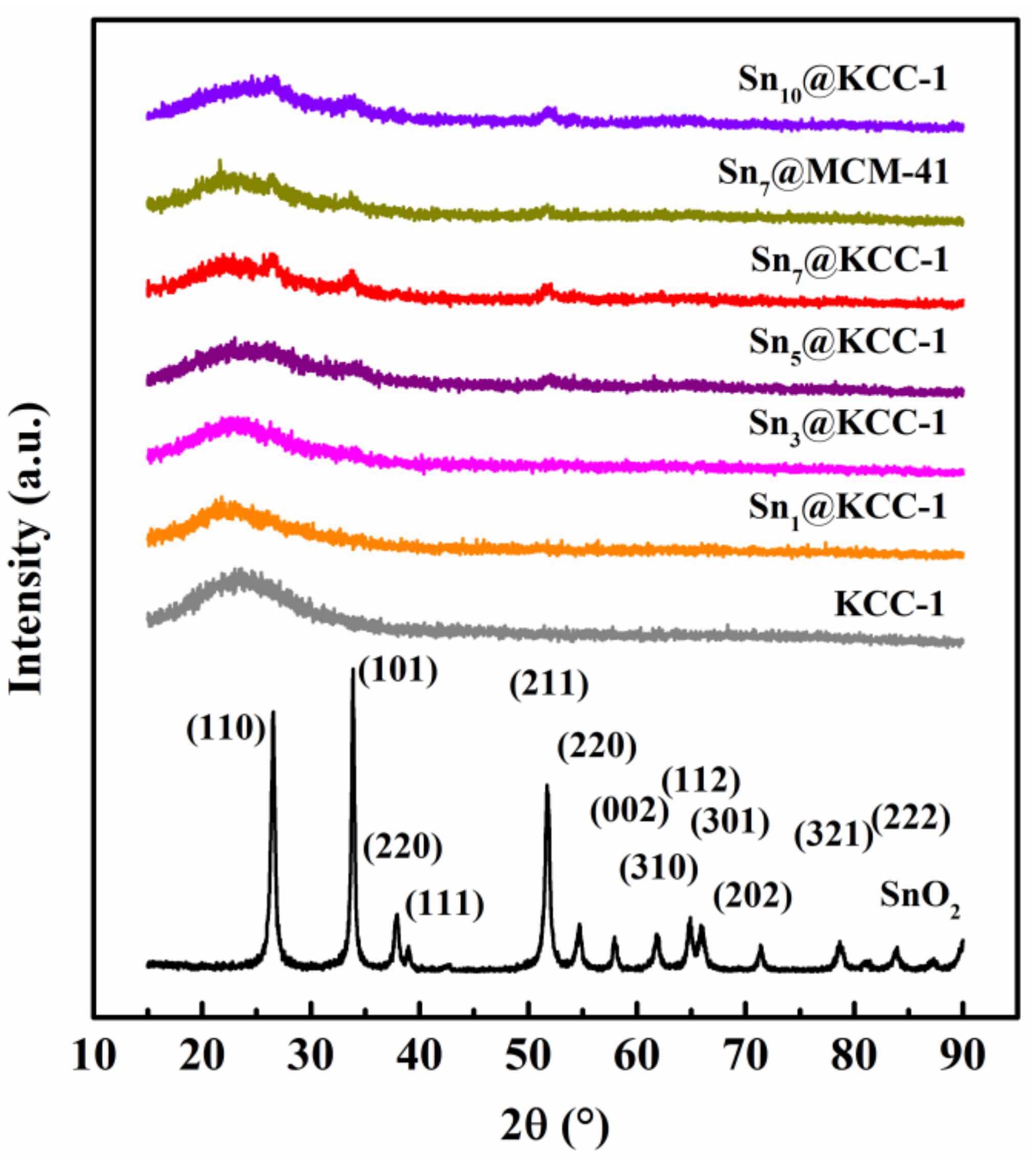
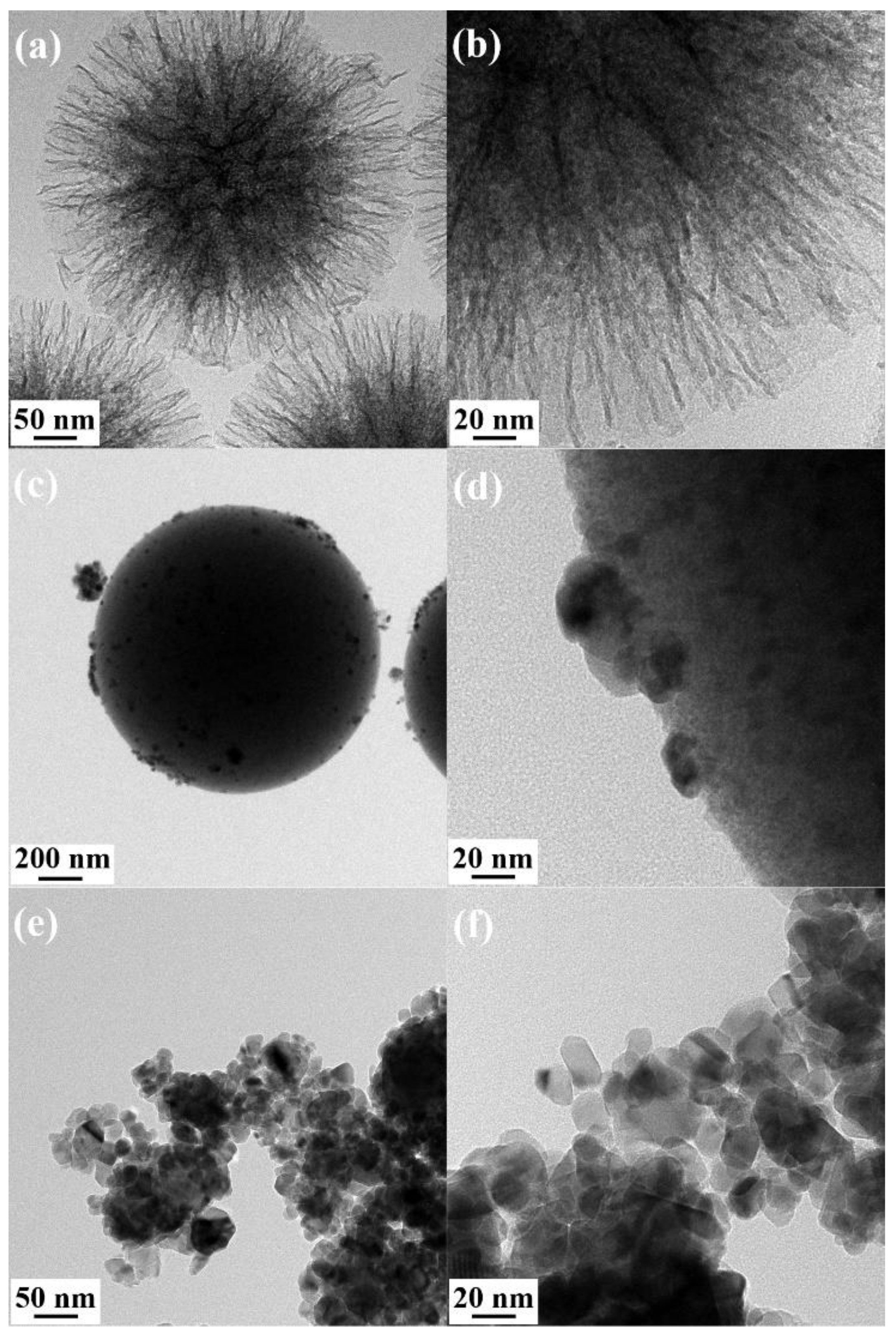
2.1. Basic Morphological Characteristics

The morphologies of KCC-1, Sn7@KCC-1, Sn7@MCM-41, and pure SnO2 catalysts were investigated via SEM. The SEM image (Figure 1d) shows that the pure SnO2 active components were agglomerated microspheres. Figure 1a,b reveals that KCC-1 featured a fibrous microsphere morphology resembling flowers, with an average spherical diameter of ~1500 nm. This morphology remained largely unchanged after SnO2 loading. This structure was conducive to heterogeneous catalytic reactions occurring on the catalyst surface. In the case of the Sn7@MCM-41 catalyst (Figure 1c), the SnO2 particles were distributed within the MCM-41 support, with slight agglomeration.

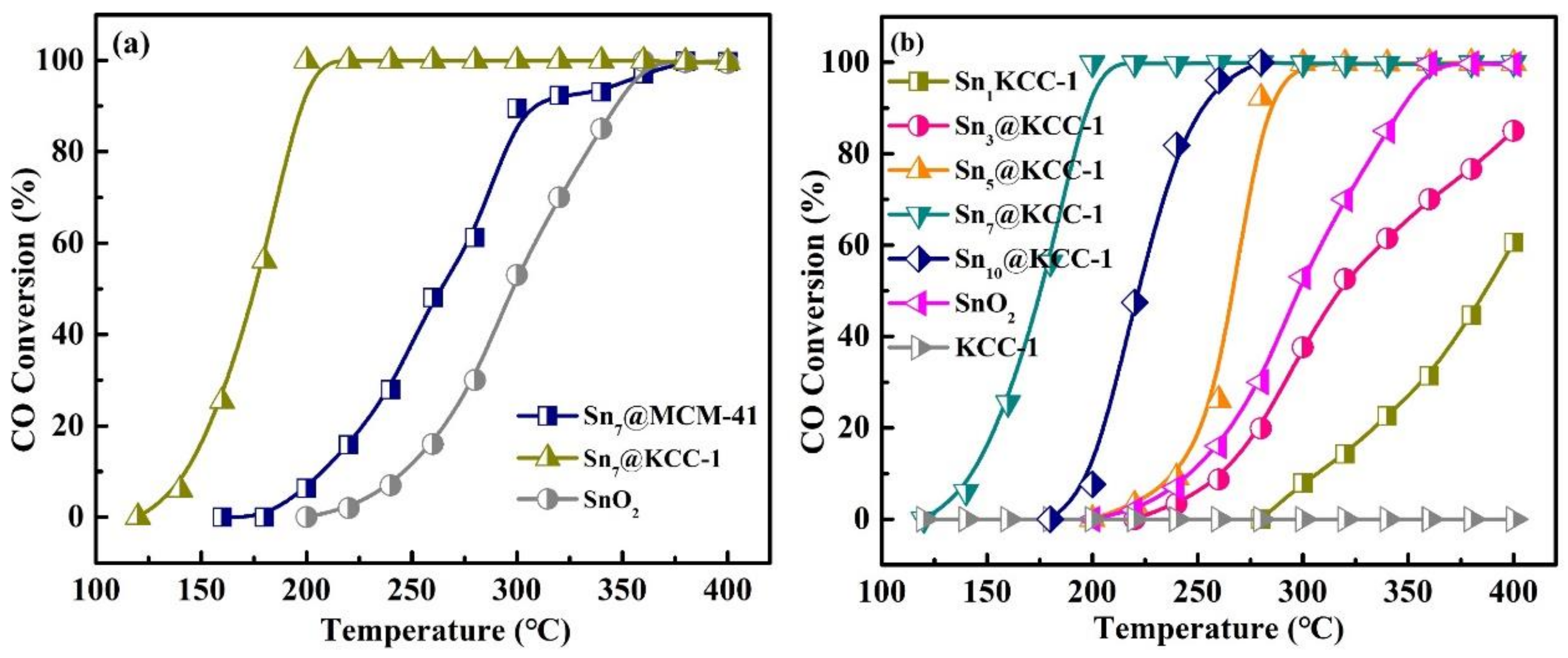
2.2. Evaluation of Catalytic Activity

The CO catalytic oxidation performance of pure SnO2, Sn7@KCC-1, and Sn7@MCM-41 catalysts was evaluated, and the results are shown in Figure 2a. The Sn7@KCC-1 catalyst exhibited a better CO catalytic activity than that of SnO2 and Sn7@MCM-41 catalysts, with over 90% CO conversion achieved over 175 °C. As displayed in Figure 2b, the Snx@KCC-1 catalysts exhibited excellent CO catalytic activity, especially the Sn7@KCC-1 catalyst, indicating that flower-like fibrous microspheres were beneficial to the heterogeneous catalytic reaction. The CO conversion of Sn10@KCC-1 was lower than that of Sn7@KCC-1, which may be caused by the aggregation of high-content active components, which was also shown in other reported catalysts [26,27]. The CO conversion stability of the Snx@KCC-1 catalyst was conducted at 200 °C, and the result is presented in Figure S1. After a 25 h test, almost no reduction in CO catalytic activity for the Sn7@KCC-1 catalyst was found, indicating excellent stability.
The lattice structures of Snx@KCC-1 and related catalysts were analyzed via XRD, and the results are shown in Figure 3. Strong diffraction peaks corresponding to different crystal faces of pure SnO2, such as (110), (101), (220), and (211), were observed. Additionally, the Snx@KCC-1 catalysts featured a broad diffraction peak at a 2θ value of 22.58, attributable to the typical diffraction peak of the amorphous SiO2 present in the mesoporous molecular sieve KCC-1 [16]. These results suggested that SnO2 existed on the surface of KCC-1 in an amorphous form, which was conducive to CO catalytic removal on the catalyst surface.
The morphology and pore structure of Snx@KCC-1 catalysts play a crucial role in heterogeneous catalysis. No distinct lattice structures for KCC-1 and SnO2 were observed in the high-resolution transmission electron micrographs of Sn7@KCC-1, Sn7@MCM-41, and pure SnO2 catalysts (Figure 4). This indicates that the SnO2 NPs were uniformly dispersed within the KCC-1 and/or MCM-41 support, particularly within KCC-1. This uniform dispersion ensured effective contact between the catalyst surface’s active component and gas molecules (CO and O2). Additionally, the high-angle annular dark-field scanning transmission electron microscopy and energy-dispersive X-ray spectroscopy mapping results (Figure S2) revealed well-distributed SnO2 NPs on KCC-1, demonstrating the nonexistence of active component accumulation. The mesoporous molecular sieve KCC-1 exhibited a unique fibrous structure (flower-like fibrous microspheres). This structure allowed the SnO2 NPs to be supported on the surface of the fibrous structure rather than in the pores, resulting in smaller particle sizes for the SnO2 NPs, with some even less than 10 nm, which was an advantage of the KCC-1 molecular sieve compared with MCM-41. Consequently, the Snx@KCC-1 catalysts exhibited excellent CO catalytic activity.
The nitrogen (N2) adsorption–desorption isotherms and corresponding BJH pore size distribution curves of SnO2, KCC-1, SnOx/KCC-1, and Sn7@MCM-41 catalysts in the relative pressure (P/P0) range of 0.05–0.25 are presented in Figure 5, and the analysis results are listed in Table 1. According to the classification by the International Union of Pure and Applied Chemistry (IUPAC), the adsorption–desorption isotherms of Snx@KCC-1 belonged to type IV, with a typical H3-type hysteresis loop, while the hysteresis loop of Sn7@MCM-41 was H2-type [28,29]. Table 1 provides the specific surface area and pore volume data. Pure SnO2 featured a low specific surface area of only 19 m2/g and a small pore volume of 0.16 cm3/g. In contrast, KCC-1 exhibited a significantly higher specific surface area of 552 m2/g and a maximum pore volume of 1.93 cm3/g. MCM-41 exhibited an even higher specific surface area of 1216 m2/g and a pore volume of 0.96 cm3/g, exceeding that of pure SnO2. When doped with SnO2 NPs, both Snx@KCC-1 and Sn7@MCM-41 showed a decrease in specific surface area, pore volume, and pore size compared to their non-doped counterparts. Specifically, as the doping of SnO2 NPs increased from 1% to 10%, the specific surface area of Snx@KCC-1 decreased from 529 to 269 m2/g, and the pore volume decreased from 1.91 to 0.95 cm3/g. Analysis of the pore size distribution of Snx@KCC-1 revealed the presence of two distinct pore sets: a unique mesoporous pore with a size of 2.7 nm embedded within the flower-like fibrous microspheres structure of the KCC-1 molecular sieve and a surface layer stacked pore with a size of 20 nm.
The reducibility of the prepared Snx@KCC-1 catalysts was investigated via the H2-TPR technique. As shown in Figure S3, consistent with previous findings, a single wide peak was observed around 703.4 °C for pure SnO2, corresponding to the reduction of Sn4+ to Sn0 [27]. The reduction peak temperature of Snx/KCC-1 catalysts was ~100 °C lower than that of pure SnO2, indicating excellent redox properties of the catalysts. The lower reduction temperature suggests that CO oxidation was more likely to occur on the Snx/KCC-1 catalyst surface.
To further examine the oxidation state of SnO2 in the Snx@KCC-1 catalysts, XPS analysis was performed on the samples before and after CO oxidation cycles. XPS is a surface-sensitive technique that provides information about the chemical states of components on the catalyst surface. The Sn 3d XPS spectra are shown in Figure 6. The doublet peaks observed at binding energies of approximately 495.5 and 487.1 eV correspond to Sn 3d3/2 and 3d5/2 for Sn4+ species, respectively [30]. The binding energies of both peaks for the different SnO2 loadings remained nearly unchanged, indicating that increasing the SnO2 loading did not alter the chemical states of Sn species on the Snx@KCC-1 catalyst surface. Moreover, as the SnO2 loading increased, the amount of Sn4+ species on the Sn7@KCC-1 catalyst reached its highest value, consistent with the H2-TPR results. These Sn species are considered active centers for activating reactants (CO and O2); hence, having a greater abundance of Sn species with higher positive valences promotes the catalytic oxidation of CO.

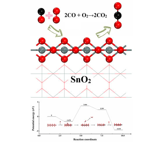
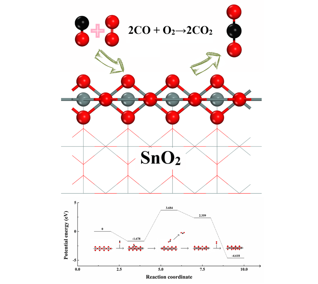
2.3. Adsorption of CO and O2 on SnO2 (110) Catalyst Surface

The optimized structure of the SnO2 (110) catalyst (Figure 7) reveals the intriguing nature of the SnO2 surfaces, which exhibited two potential oxidation states of tin (+2 and +4), reduced atomic coordination, and advantageous compositional alterations and reconstructions. According to the calculated results, the surface Sn and O atoms were likely the adsorption sites for CO and O2 gas molecules. The use of non-precious metal (SnO2) in the catalytic oxidation of CO serves as a design principle for the development of advanced catalytic systems with a wide range of applications.
During CO catalytic oxidation, the adsorption of CO and O2 on the surface of the SnO2 (110) catalyst played a crucial role. Therefore, the adsorption of CO and O2 on the SnO2 (110) surface was investigated separately (Figure 8). Single O2 molecule adsorption was observed around the Sn active center on the SnO2 (110) surface. The formed Sn–O bond featured a length of 2.147 Å, with an adsorption energy of −6.14 eV. According to the projected density of states (PDOS) results, in the adsorption configurations of both CO and O2, the highest occupied molecular orbital of O2 hybridized with the lowest unoccupied molecular orbital of Sn. CO, as the most important reactant, exhibited an adsorption energy value of −1.678 eV on the Sn surface, resulting in the generation of CO32− species. The lengths of the newly formed C–O bonds were 2.116 Å and 2.121 Å, respectively. The PDOS analysis confirmed that the adsorption of these gas molecules on the SnO2 (110) surface involved chemisorption, indicating their effective activation by the catalyst surface. Therefore, CO can be efficiently converted on the SnO2 (110) catalyst surface.

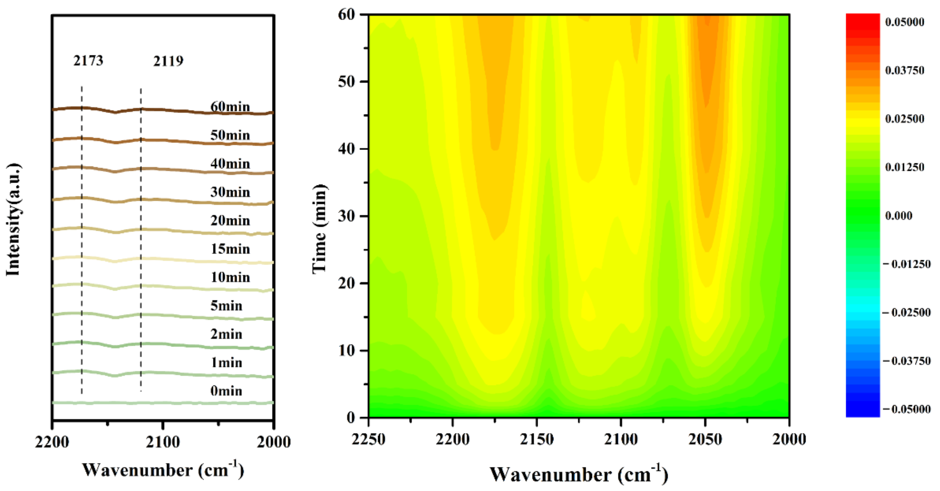
2.4. Instantaneous Intermediates on the Catalysts

To further investigate the instantaneous intermediates of the CO + O2 catalytic oxidation reaction on the Sn7@KCC-1 catalyst surface, a transient CO + O2 adsorption experiment was conducted at 200 °C. Figure 9 presents the CO + O2 reaction spectra of the Sn7@KCC-1 catalyst. The peaks at approximately 2119 and 2173 cm−1 can be attributed to the linearly adsorbed CO species on surface Sn4+ centers (Sn4+-CO) [31]. These results indicate that CO was readily adsorbed on the surface of the Sn7@KCC-1 catalyst with 7% SnO2, forming active intermediates. This finding is consistent with the DFT calculation results (Figure 8). The identified species on the Sn7@KCC-1 catalyst surface suggest that the catalytic oxidation of CO predominantly followed the Mars–van Krevelen (MvK) mechanism.
The CO removal step reaction process on the SnO2 (110) catalyst surface was further explored through DFT calculations. The obtained transient CO + O2 reaction DRIFTS profiles of Sn7@KCC-1 catalyst results are shown in Figure 10. The detailed reaction pathway was as follows: ① CO → CO32−ads, ② CO32−ads → CO2free+SnOx−1, ③ SnOx−1+O2 → SnOx+1. As shown in Figure 10, CO gas molecules first adsorbed onto the SnO2 (110) surface, forming the CO32− species. Subsequently, CO2 was dissociated from the SnO2 (110) catalyst surface; this process was accompanied by the formation of an oxygen vacancy structure (SnOx−1). This step, with a reaction energy (Er) of 5.362 eV, may determine the rate of CO catalytic oxidation. The physicochemical properties of the catalyst remained unchanged before and after the chemical reaction. Therefore, the SnOx−1 structure was restored through the oxidation of O2 gas molecules. In summary, the catalytic oxidation of CO on the SnO2 (110) surface followed the MvK mechanism. The CO gas molecule reacted with the lattice oxygen (Olatt) on the SnO2 (110) surface, forming CO32− species. Subsequently, CO2 was dissociated from the SnO2 (110) catalyst, and gaseous O2 refilled the oxygen vacancy, leading to the restoration of the catalyst. These findings are consistent with the literature reports [32].

3. Conclusions

A series of Snx@KCC-1 catalysts were prepared by loading SnO2 NPs onto flower-like fibrous microspheres of mesoporous silica (KCC-1), in which the SnO2 NPs were supported and highly dispersed. The obtained Snx/KCC-1 catalysts exhibited excellent CO catalytic activity, with the Sn7@KCC-1 catalyst showing the highest performance, achieving 90% CO conversion at ~175 °C. KCC-1 exhibited a significantly larger specific surface area of 552 m2/g and a maximum pore volume of 1.93 cm3/g. The SnO2 NPs on the KCC-1 surface were highly dispersed in an amorphous form, and the strong interaction between SnO2 NPs and KCC-1 contributed to the catalytic removal of CO on the catalyst surface. The presence of Sn4+ species as active centers facilitated the activation of CO and O2, thereby promoting the catalytic oxidation of CO. The CO catalytic removal pathway was established through a combination of in situ DRIFTS and DFT calculations. The oxidation of CO on the SnO2 (110) surface followed the MvK mechanism, with the detailed reaction pathway as follows: ① CO → CO32−ads, ② CO32−ads → CO2free+SnOx−1, ③ SnOx−1+O2 → SnOx+1. This study provides valuable insights into the design of high-efficiency non-precious metal catalysts for CO catalytic oxidation.

4. Experimental

4.1. Catalyst Preparation

The required reagents were supplied by Sinopharm Chemical Reagent Co., Ltd. (Beijing, China). The KCC-1 [33] and MCM-41 [34] supports were prepared according to previously reported procedures.
The detailed preparation process of the KCC-1 support was as follows. First, 60 mL of cyclohexane (99.50%), 3.00 mL of n-pentanol (99.50%), and 5.00 g of tetraethyl orthosilicate (TEOS, 99%, 18.92 mmol) were mixed at 25 °C to obtain liquid A. Then, 2.00 g of cetyltrimethylammonium bromide (CTAB, 99%, 5.48 mmol) and 1.20 g of urea (99%, 19.98 mmol) were dissolved in 60 mL of deionized water to obtain liquid B. Liquid B was slowly poured into liquid A, and the resulting solution was thoroughly mixed. The mixture was then transferred into a stainless steel autoclave, sealed, and maintained at 120 °C for 6 h with constant stirring. After cooling to 25 °C, the precipitation was collected by filtering and washing with acetone (99.50%) and ethanol (99.50%). Then, the final precipitation was dried at 80 °C overnight and calcined in a muffle furnace at 550 °C for 6 h to remove the template agent (the heating 2 °C·min−1). Finally, the white powder of mesoporous molecular sieve material KCC-1 was obtained.
The detailed preparation process of the MCM-41 support was as follows. Cetyltrimethylammonium bromide, as the mesoporous directing agent, was dissolved in water and stirred until it became colorless. Tetraethyl orthosilicate as the Si source was added to the mixture after 30 min. The pH value of this gel mixture was adjusted to 10 by adding NH3·H2O. After being stirred for 3 h, the gel solution was further aged and crystallized at 65 °C for 18 h in an oven. Finally, the solution was filtered, washed with ultrapure water until the pH reached 7, dried, and calcined at 550 °C for 6 h.
The detailed preparation process of the Snx/KCC-1 support was as follows. First, 0.50 g of KCC-1 (or MCM-41) supports was impregnated in a solution containing 10.00 mL of ethylene glycol (99.50%) and the appropriate amount of Sn(NO3)4·6H2O (≥99.00%). The resulting solid–liquid mixture was dried in a vacuum oven at 80 °C until the solvent completely evaporated. Then, the resulting solid was calcined in a tube furnace at 550 °C in an N2 atmosphere for 4 h. Finally, the atmosphere was switched to air and maintained at 550 °C for 2 h. The obtained catalysts were named Snx/KCC-1 (or Snx@MCM-41) catalyst, where x represents the mass fraction of SnO2 loading.
For comparison, pristine SnO2 without a three-dimensional spatial structure was prepared through a homogeneous precipitation method. In a typical process, an appropriate amount of Sn(NO3)4·6H2O (≥99.00%) was first dissolved in deionized water (with a Sn4+ concentration of 0.1 mol·L−1). After 30 min of stirring, ammonia solution (Sinopharm, 25–28 wt.%) was added dropwise to the solution until the pH reached ~10. The mixture was stirred at 25 °C for 3 h. Finally, the precipitate was filtered, washed, dried, and calcined using the same calcination procedures as mentioned above.

4.2. Evaluation of the Catalytic Performance

The CO catalytic oxidation ability of the obtained catalysts was tested in a self-assembled fixed-bed quartz reactor with continuous flow. Furthermore, the Weisz–Prater Criterion was used to assess the effectiveness of internal diffusion. The CO oxidation activity tests were evaluated in a fixed-bed quartz reactor using a U-shaped quartz tube with an inner diameter of 6 mm under the following typical reaction condition: [CO] = 1 vol.%, [O2] = 21 vol.%, N2 as balance gas with a total flow rate of 30 mL min−1, and the catalyst mass for each test is 50 mg. GC9310 gas chromatograph (equipped with a TDX-01 column and a TCD detector) and N-2000 workstation were used for collecting and analyzing the reactants and products. The conversion of CO ( X CO ) was calculated using Equation (1):
X CO = 1 S CO - outlet S CO - inlet × 100 %
where S CO - outlet and S CO - inlet   are the CO concentration in the inlet and outlet gas streams corresponding to the CO inlet and outlet peak areas, respectively, which are derived from the gas chromatograph responses using the modified area normalization method.

4.3. Catalyst Characterization

Powder X-ray diffraction (XRD) patterns of the catalysts were obtained using a Rigaku SmartLab 9 kW (Tokyo, Japan) diffractometer with Cu Kα radiation (λ = 1.5418 Å). The instrument was operated at 40 kV and 150 mA, and scans were collected in the 2θ range from 10° to 90°, with a step of 2° min−1 to analyze the phase structure. The specific surface areas of the catalysts were determined through nitrogen adsorption experiments at 77 K using a Micromeritics ASAP2020 instrument (Micromeritics Corporate, Norcross, GA, USA). Prior to the test, 100 mg of catalyst was degassed at 300 °C for 5 h. Nitrogen adsorption and desorption were then performed to obtain the N2 adsorption–desorption curve. The specific surface areas of the samples were calculated through the Brunauer–Emmett–Teller (BET) method in the relative pressure (p/p0) range of 0.05–0.25. The pore size distributions of the samples were calculated through the Barrett–Joyner–Halenda (BJH) method. Scanning electron microscopy (SEM) and transmission electron microscopy images were captured using a Hitachi S-4800 field emission scanning electron microscope (Hitachi Ltd, Tokyo, Japan) and a Tecnai™ F30 transmission electron microscope (Fei company, Hillsboro, OR, USA), respectively. XPS was performed using a PHI-5000C ESCA system (PerkinElmer, Waltham, MA, USA) with a single Mg-K X-ray source operated at 250 W and 14 kV. The spectra were obtained at ambient temperature under ultrahigh vacuum conditions. The binding energies were calibrated using the standard C 1s peak of graphite at 284.8 eV. In situ DRIFTS experiments were conducted using an is50 spectrometer equipped with a liquid nitrogen-cooled mercury cadmium telluride A (MCT-A) detector and a Harrick Scientific DRIFTS cell. Prior to each test, each sample was pretreated at 400 °C for 60 min under a N2 flow of 30 mL·min−1. The background spectrum at the desired temperature was collected after pretreatment in an N2 atmosphere, which was deduced from the sample spectra for each measurement. For the in situ transient reactions of pre-adsorbed CO, the catalysts were exposed to 1% CO/N2 (30 mL·min−1) for adsorption at 100 °C after pretreatment. After half an hour, the catalyst was purged with N2 for 10 min. Then, the sample was subjected to a flow of 21% O2/N2 (30 mL·min−1), and the reaction process was recorded as a function of time.

4.4. DFT Calculation

The Vienna Ab-initio Simulation Package (VASP) was adopted for the density functional theory (DFT) calculations [35,36,37]. The Projector Augmented Wave (PAW) method was used to solve the Kohn–Sham equations [38]. The generalized gradient approximation and Perdew–Burke–Ernzerhof (GGA-PBE) exchange association functional were adopted [39]. A dipole correction was introduced to describe the total energy and eliminate dipole moment, which is caused by metal atoms adsorption [40].
During the adsorption calculations, a kinetic energy cutoff of 500 eV was used. A Gamma-centered 1 × 1 × 1 mesh was employed for Brillouin zone integration. Geometry optimization was performed using the whole ad-molecule model relaxation. A vacuum layer with a thickness of at least 20 Å in the z-direction was added to simulate the surfaces and ensure that the reaction was not influenced by the next layer. The convergence criteria for electronic and geometry relaxation were set to 10−5 eV and 0.01 eV·Å−1, respectively. Adsorption was allowed on only one side of the exposed surface, and the dipole moment was corrected accordingly in the z-direction. The adsorption energy (Eads) of reaction gas on the SbPdV/N-TiO2 (101) surface was calculated using Equation (2):
Eads = Egas-structure − (Egas + Estructure)
where Eads, Estructure, and Egas are the total energies of adsorbed reaction gas over SnO2 structure (110) surface, interacting SnO2 (110) structure surface, and the isolated gas molecules in vacuum, respectively.
The reaction energy (Er) is defined as Equation (3):
Er = EFSEIS
EIS and EFS are the energies of the initial and final states, respectively.

Supplementary Materials

The following supporting information can be downloaded at: https://www.mdpi.com/article/10.3390/catal13081156/s1. Evaluation of the catalytic performance. Figure S1: CO conversion stability at 200 °C of Sn7@KCC-1 catalyst in the condition of 1% CO + 21% O2, balanced by N2, and WHSV = 18, 000 mL gcat.−1 h−1. Figure S2: HAADF-STEM and EDX-mapping of Sn7@KCC-1. Figure S3: H-TPR of Sn1@KCC-1, Sn1@KCC-1 and SnO2 catalysts.

Author Contributions

Conceptualization by G.L. and Y.Z.; supervision by Y.Z. and J.Y.; writing—original draft by J.Y., Y.L., C.W. and W.F.; writing—review and editing by G.L., Z.Z., H.P., W.L. and S.Z.; methodology by G.L., H.P. and S.Z. All authors have read and agreed to the published version of the manuscript.

Funding

This work was supported by the National Natural Science Foundation of China (21976078, 22276086), the Natural Science Foundation of Jiangxi Province (20202ACB213001), Hubei Provincial Natural Science Foundation of China (2020CFA096), all of which are gratefully acknowledged by the authors.

Data Availability Statement

The data are contained within the article.

Conflicts of Interest

The authors declare no conflict of interest.

References

  1. Lu, Z.S.; Meng, S.J.; Ma, Z.Y.; Yang, M.X.; Ma, D.W.; Yang, Z.X.; Talib, S.H. Electronic and catalytic properties of Ti single atoms@SnO2 and its implications on sensing mechanism for CO. Appl. Surf. Sci. 2022, 594, 153500. [Google Scholar] [CrossRef]
  2. May, Y.A.; Wang, W.W.; Yan, H.; Wei, S.; Jia, C.J. Insights into facet-dependent reactivity of CuO–CeO2 nanocubes and nanorods as catalysts for CO oxidation reaction. Chin. J. Catal. 2020, 41, 1017–1027. [Google Scholar] [CrossRef]
  3. Qian, C.Y.; Bian, J.W.; Ju, F.; Ling, H. Effect of PdSx on sulfur resistance of Pd-Based catalysts for CO oxidation. Ind. Eng. Chem. Res. 2023, 62, 3038–3049. [Google Scholar] [CrossRef]
  4. Zhang, X.D.; Zhang, X.L.; Song, L.; Hou, F.L.; Yang, Y.Q.; Wang, Y.X.; Liu, N. Enhanced catalytic performance for CO oxidation and preferential CO oxidation over CuO/CeO2 catalysts synthesized from metal organic framework: Effects of preparation methods. Int. J. Hydrogen Energy 2018, 43, 18279–18288. [Google Scholar] [CrossRef]
  5. Twigg, M.V. Catalytic control of emissions from cars. Catal. Today 2011, 163, 33–41. [Google Scholar] [CrossRef]
  6. Xiang, G.H.; Zhao, S.; Wei, C.D.; Liu, C.Y.; Fei, H.L.; Liu, Z.G.; Yin, S.F. Atomically dispersed Au catalysts for preferential oxidation of CO in H2-rich stream. Appl. Catal. B Environ. 2021, 296, 120385–120396. [Google Scholar] [CrossRef]
  7. Xin, Y.; Zhang, N.N.; Lv, Y.N.; Wang, J.; Li, Q.; Zhang, Z.L. Room-Temperature CO oxidative coupling for oxamide production over interfacial Au/ZnO catalysts. ACS Catal. 2023, 13, 735–743. [Google Scholar]
  8. Liu, Q.L.; Yang, P.; Tan, W.; Yu, H.W.; Ji, J.W.; Wu, C.; Cai, Y.D.; Xie, S.H.; Liu, F.D.; Hong, S.; et al. Fabricating robust Pt clusters on Sn-Doped CeO2 for CO oxidation: A deep insight into support engineering and surface structural evolution. Chem. Eur. J. 2023, 29, 2034–2045. [Google Scholar]
  9. Wu, C.L.; Guo, Z.Z.; Chen, X.Y.; Liu, H. Cu/CeO2 as efficient low-temperature CO oxidation catalysts: Effects of morphological structure and Cu content. React. Kinet. Mech. Cat. 2020, 131, 691–706. [Google Scholar] [CrossRef]
  10. Liu, X.S.; Jin, Z.N.; Lu, J.Q.; Wang, X.X.; Luo, M.F. Highly active CuO/OMS-2 catalysts for low-temperature CO oxidation. Chem. Eng. J. 2010, 162, 151–157. [Google Scholar] [CrossRef]
  11. Dae, J.M.; Shin, D.; Jeong, H.; Kim, B.S.; Han, J.W.; Lee, H. Highly Water-Resistant La-doped Co3O4 Catalyst for CO oxidation. ACS Catal. 2019, 9, 10093–10100. [Google Scholar]
  12. Bulavchenko, O.A.; Konovalova, V.P.; Saraev, A.A.; Kremneva, A.M.; Rogov, V.A.; Gerasimov, E.Y.; Afonasenko, T.N. The catalytic performance of CO oxidation over MnOx-ZrO2 Catalysts: The role of synthetic routes. Catalysts 2022, 13, 57–72. [Google Scholar] [CrossRef]
  13. Liu, Y.N.; Mao, D.S.; Yu, J.; Guo, X.M.; Ma, Z. Low-temperature CO oxidation on CuO-CeO2 catalyst prepared by facile one-step solvothermal synthesis: Improved activity and moisture resistance via optimizing the activation temperature. Fuel 2023, 332, 126196. [Google Scholar] [CrossRef]
  14. Zhao, W.J.; Li, X.; Dang, H.; Wu, R.F.; Wang, Y.Z.; Zhao, Y.X. Effect of Sn addition on the catalytic performance of a Pd–Cu/attapulgite catalyst for room-temperature CO oxidation under moisture-rich conditions. Reac. Kinet. Mech. Cat. 2021, 134, 759–775. [Google Scholar] [CrossRef]
  15. Peng, H.G.; Peng, Y.; Xu, X.L.; Fang, X.Z.; Liu, Y.; Cai, J.X.; Wang, X. SnO2 nano-sheet as an efficient catalyst for CO oxidation. Chin. J. Catal. 2015, 36, 2004–2010. [Google Scholar] [CrossRef]
  16. Peng, H.G.; Zhang, X.H.; Han, X.; You, X.J.; Lin, S.X.; Chen, H.; Liu, W.M.; Wang, X.; Zhang, N.; Wang, Z.; et al. Catalysts in coronas: A surface spatial confinement strategy for high-performance catalysts in methane dry reforming. ACS Catal. 2019, 9, 9072–9080. [Google Scholar] [CrossRef]
  17. Castillejos, E.; Debouttiere, P.J.; Roiban, L.; Solhy, A.; Martinez, V.; Kihn, Y.; Ersen, O.; Philippot, K.; Chaudret, B.; Serp, P. An efficient strategy to drive nanoparticles into carbon nanotubes and the remarkable effect of confinement on their catalytic performance. Angew. Chem. Int. Ed. Eng. 2009, 48, 2529–2533. [Google Scholar] [CrossRef] [PubMed]
  18. Wang, D.; Yang, G.; Ma, Q.; Wu, M.; Tan, Y.; Yoneyama, Y.; Tsubaki, N. Confinement effect of carbon nanotubes: Copper nanoparticles filled carbon nanotubes for hydrogenation of methyl acetate. ACS Catal. 2012, 2, 1958–1966. [Google Scholar] [CrossRef]
  19. Deng, D.H.; Chen, X.Q.; Yu, L. A single iron site confined in a graphene matrix for the catalytic oxidation of benzene at room temperature. Sci. Adv. 2015, 1, 1500462. [Google Scholar] [CrossRef] [PubMed] [Green Version]
  20. Baudouin, D.; Szeto, K.C.; Laurent, P.; Mallmann, A.D.; Fenet, B.; Veyre, L.; Rodemerck, U.; Coperet, C.; Thieuleux, C. Nickel-silicide colloid prepared under mild conditions as a versatile Ni precursor for more efficient CO2 reforming of CH4 catalysts. J. Am. Chem. Soc. 2012, 134, 20624–20627. [Google Scholar] [CrossRef] [PubMed]
  21. Bian, Z.; Suryawinata, I.Y.; Kawi, S. Highly carbon resistant multicore-shell catalyst derived from Ni-Mg phyllosilicate nanotubes@silica for dry reforming of methane. Appl. Catal. B Environ. 2016, 195, 1–8. [Google Scholar] [CrossRef]
  22. Zhang, X.H.; Zhang, L.; Peng, H.G.; You, X.; Peng, C.; Xu, X.; Liu, W.M.; Fang, X.; Wang, Z.; Zhang, N.; et al. Nickel nanoparticles embedded in mesopores of AlSBA-15 with a perfect peasecod-like structure: A catalyst with superior sintering resistance and hydrothermal stability for methane dry reforming. Appl. Catal. B Environ. 2018, 224, 488–499. [Google Scholar] [CrossRef]
  23. Liu, D.; Quek, X.Y.; Cheo, W.N.E.; Lau, R.; Borgna, A.; Yang, Y. MCM-41 supported nickel-based bimetallic catalysts with superior stability during carbon dioxide reforming of methane: Effect of strong metal–support interaction. J. Catal. 2009, 266, 380–390. [Google Scholar] [CrossRef]
  24. Dadras, J.; Jimenez-Izal, E.; Alexandrova, A.N. Alloying Pt Sub-nano-clusters with boron: Sintering preventative and coke antagonist. ACS Catal. 2015, 5, 5719–5727. [Google Scholar] [CrossRef] [Green Version]
  25. Cai, W.; Zhong, Q.; Zhao, W.; Bu, Y. Focus on the modified CexZr1−xO2 with the rigid benzene-muti-carboxylate ligands and its catalysis in oxidation of NO. Appl. Catal. B Environ. 2014, 158, 258–268. [Google Scholar] [CrossRef]
  26. Feng, B.; Shi, M.; Liu, J.X.; Han, X.C.; Lan, Z.J.; Gu, H.J.; Wang, X.X.; Sun, H.M.; Zhang, Q.X.; Li, H.X.; et al. An efficient defect engineering strategy to enhance catalytic performances of Co3O4 nanorods for CO oxidation. J. Hazard. Mater. 2020, 394, 122540. [Google Scholar] [CrossRef]
  27. Wang, Y.; Liu, C.; Liao, X.; Liu, Y.; Hou, J.; Pham-Huu, C. Enhancing oxygen activation on high surface area Pd-SnO2 solid solution with isolated metal site catalysts for catalytic CH4 combustion. Appl. Surf. Sci. 2021, 564, 150368. [Google Scholar] [CrossRef]
  28. Zhang, G.; Han, W.; Zhao, H.; Zong, L.; Tang, Z. Solvothermal synthesis of well-designed ceria-tin-titanium catalysts with enhanced catalytic performance for wide temperature NH3-SCR reaction. Appl. Catal. B Environ. 2018, 226, 117–126. [Google Scholar] [CrossRef]
  29. Bratan, V.; Munteanu, C.; Hornoiu, C.; Vasile, A.; Papa, F.; State, R.; Preda, S.; Culita, D.; Ionescu, N.I. CO oxidation over Pd supported catalysts—In situ study of the electric and catalytic properties. Appl. Catal. B Environ. 2017, 207, 166–173. [Google Scholar] [CrossRef]
  30. Wang, Z.; Huang, Z.; Brosnahan, J.T.; Zhang, S.; Guo, Y.; Guo, Y.; Wang, L.; Wang, Y.; Zhan, W. Ru/CeO2 Catalyst with Optimized CeO2 Support Morphology and Surface Facets for Propane Combustion. Environ. Sci. Technol. 2019, 53, 5349–5358. [Google Scholar] [CrossRef]
  31. Lu, Z.; Ma, D.; Yang, L.; Wang, X.; Xu, G.; Yang, Z. Direct CO oxidation by lattice oxygen on the SnO2 (110) surface: A DFT study. Phys. Chem. Chem. Phys. 2014, 16, 12488–12494. [Google Scholar] [CrossRef] [PubMed]
  32. Liu, J.; Ji, Q.; Imai, T.; Ariga, K.; Abe, H. Sintering-Resistant Nanoparticles in Wide-Mouthed Compartments for Sustained Catalytic Performance. Sci. Rep. 2017, 7, 41773. [Google Scholar] [CrossRef] [PubMed] [Green Version]
  33. Polshettiwar, V.; Cha, D.; Zhang, X.; Basset, J.M. High-surface-area silica nanospheres (KCC-1) with a fibrous morphology. Angew. Chem. Int. Ed. Eng. 2010, 49, 9652–9656. [Google Scholar] [CrossRef] [PubMed]
  34. Zhao, X.Y.; Ren, X.Y.; Wang, Y.J.; Cao, J.P.; He, Z.M.; Yao, N.Y.; Bai, H.C.; Cong, H.L. Conversion of lignite-derived volatiles into aromatics over Zn@MCM-41 and ZSM-5 tandem catalysts with a high stability. Fuel 2023, 339, 127430. [Google Scholar] [CrossRef]
  35. Kohn, W.; Sham, L.J. Self-Consistent equations including exchange and correlation effects. Phys. Rev. 1965, 140, 1133–1138. [Google Scholar] [CrossRef] [Green Version]
  36. Dong, W.; Kresse, G.; FurthmãLler, J.; Hafner, J. Chemisorption of H on Pd (111): An ab initio approach with ultrasoft pseudopotentials. Phys. Rev. B Condens. Matter. 1996, 54, 2157–2166. [Google Scholar] [CrossRef]
  37. Kresse, G.; Furthmüller, J. Efficiency of Ab-initio total energy calculations for metals and semiconductors using a plane-wave basis set. Comp. Mater. Sci. 1996, 6, 15–50. [Google Scholar] [CrossRef]
  38. Hammer, B.; Hansen, L.B.; NoRskov, J.K. Improved adsorption energetics within density-functional theory using revised Perdew-Burke-Ernzerhof functionals. Phy. Rev. B 1999, 59, 7413–7421. [Google Scholar] [CrossRef] [Green Version]
  39. Perdew, J.P.; Burke, K.; Ernzerhof, M. Generalized gradient approximation made simple. Phys. Rev. Lett. 1996, 77, 3865–3868. [Google Scholar] [CrossRef] [Green Version]
  40. Neugebauer, J.; Scheffler, M. Adsorbate-substrate and adsorbate-adsorbate interactions of Na and K adlayers on Al (111). Phys. Rev. B Condens. Matter. 1992, 46, 16067–16080. [Google Scholar] [CrossRef] [Green Version]
Figure 1. SEM images of (a) KCC-1, (b) Sn7@KCC-1, (c) Sn7@MCM-41, and (d) pure SnO2 catalysts.
Catalysts 13 01156 g001
Figure 2. Catalytic performance of (a) pure SnO2, Sn7@KCC-1, and Sn7@MCM-41, and (b) Snx@KCC-1 catalysts with different content of SnO2 for CO oxidation, respectively. Reaction conditions: 1% CO, 21% O2, balanced by N2, and WHSV = 18,000 mL gcat.−1 h−1.
Catalysts 13 01156 g002
Figure 3. XRD patterns of Snx@KCC-1 and related catalyst materials.
Catalysts 13 01156 g003
Figure 4. TEM images of (a,b) Sn7@KCC-1, (c,d) Sn7@MCM-41, and (e,f) pure SnO2.
Catalysts 13 01156 g004
Figure 5. (a) N2 adsorption–desorption isotherms and (b) pore size distribution curves of SnOx/KCC-1 and related catalyst materials.
Catalysts 13 01156 g005
Figure 6. The Sn 3d XPS survey scans spectra of Snx@KCC-1 catalysts.
Catalysts 13 01156 g006
Figure 7. Top and side view of optimized SnO2 (110) catalyst structure.
Catalysts 13 01156 g007
Figure 8. Optimized adsorption configurations and projected density of states (PDOS) on SnO2 (110) catalyst surface for O2 and CO molecules, respectively.
Catalysts 13 01156 g008
Figure 9. The transient CO + O2 reaction DRIFTs profiles of Sn7@KCC-1 catalyst measured at 200 °C; the right figures are the mapping results derived from the DRITFs profiles.
Catalysts 13 01156 g009
Figure 10. Removal path and energy barrier of CO on the SnO2 (110) catalyst surface.
Catalysts 13 01156 g010
Table 1. Textural parameters of SnKCC-1 and related materials.
Catalyst SamplesSurface Area (m2/g) aPore Volume (cm3/g) bPore Size (nm) b
KCC-15521.933.5
MCM-4112160.963.2
Sn1@KCC-15291.912.7
Sn3@KCC-14991.742.7
Sn5@KCC-14221.532.7
Sn7@KCC-13150.962.7
Sn10@KCC-12690.952.7
Sn7@MCM-418070.612.9
SnO2190.1610.4
a: determined from the linear part of BET equation (P/P0 = 0.05–0.25). b: determined from BJH equation.
Disclaimer/Publisher’s Note: The statements, opinions and data contained in all publications are solely those of the individual author(s) and contributor(s) and not of MDPI and/or the editor(s). MDPI and/or the editor(s) disclaim responsibility for any injury to people or property resulting from any ideas, methods, instructions or products referred to in the content.

