
Emergent CuWO4 Photoanodes for Solar Fuel Production: Recent Progress and Perspectives

Abstract
:
1. Introduction
2. CuWO4 as a Photoanode Material
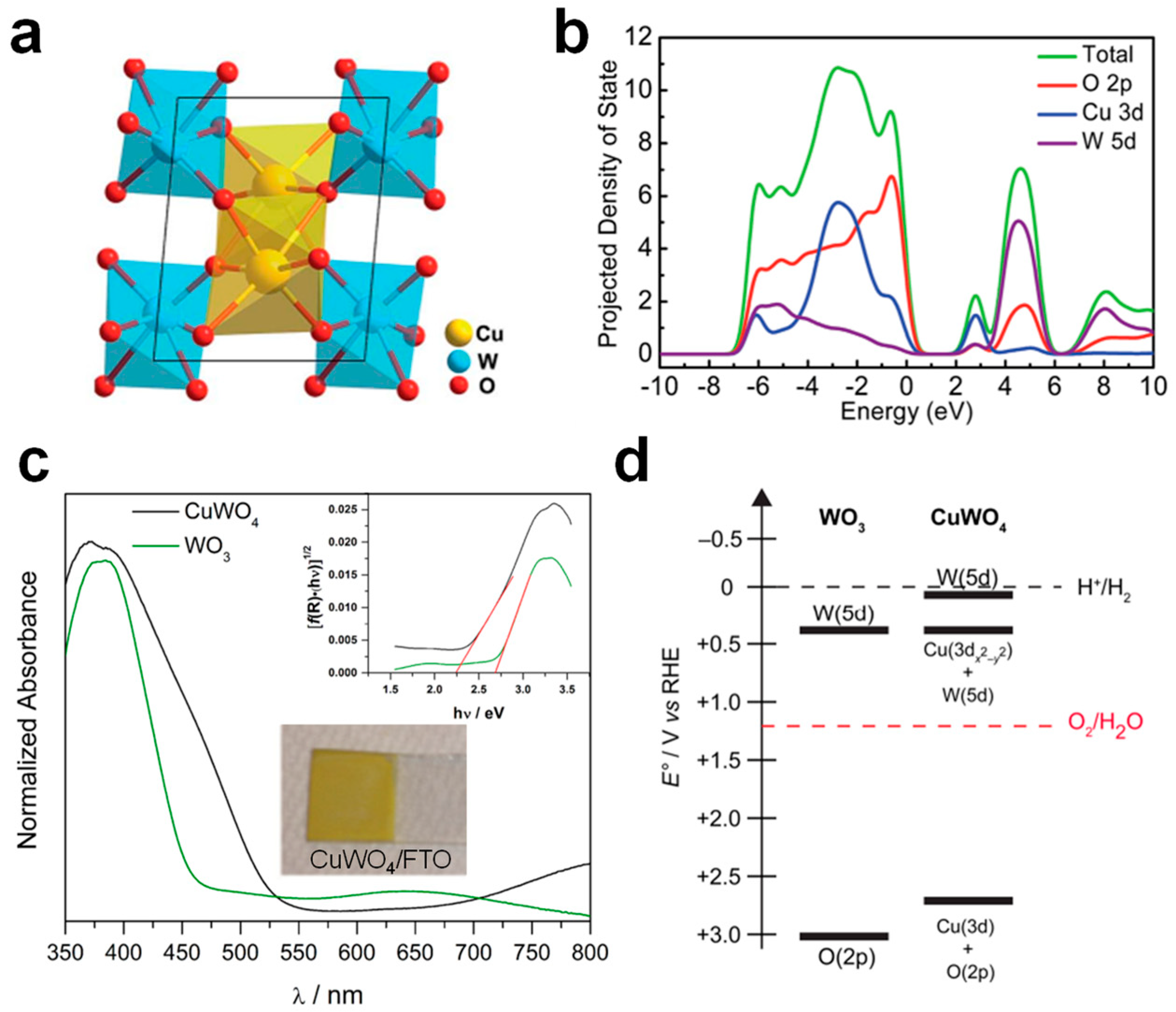
2.1. Crystal Structure of Photoactive CuWO4
2.2. Electronic Structure of Photoactive CuWO4
3. Synthesis Chemistry and Photoelectrochemical Stability
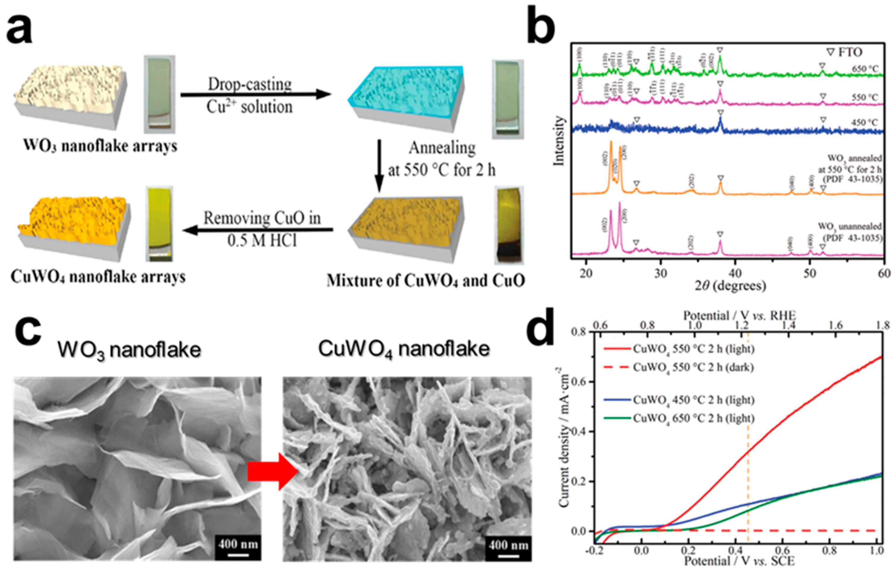
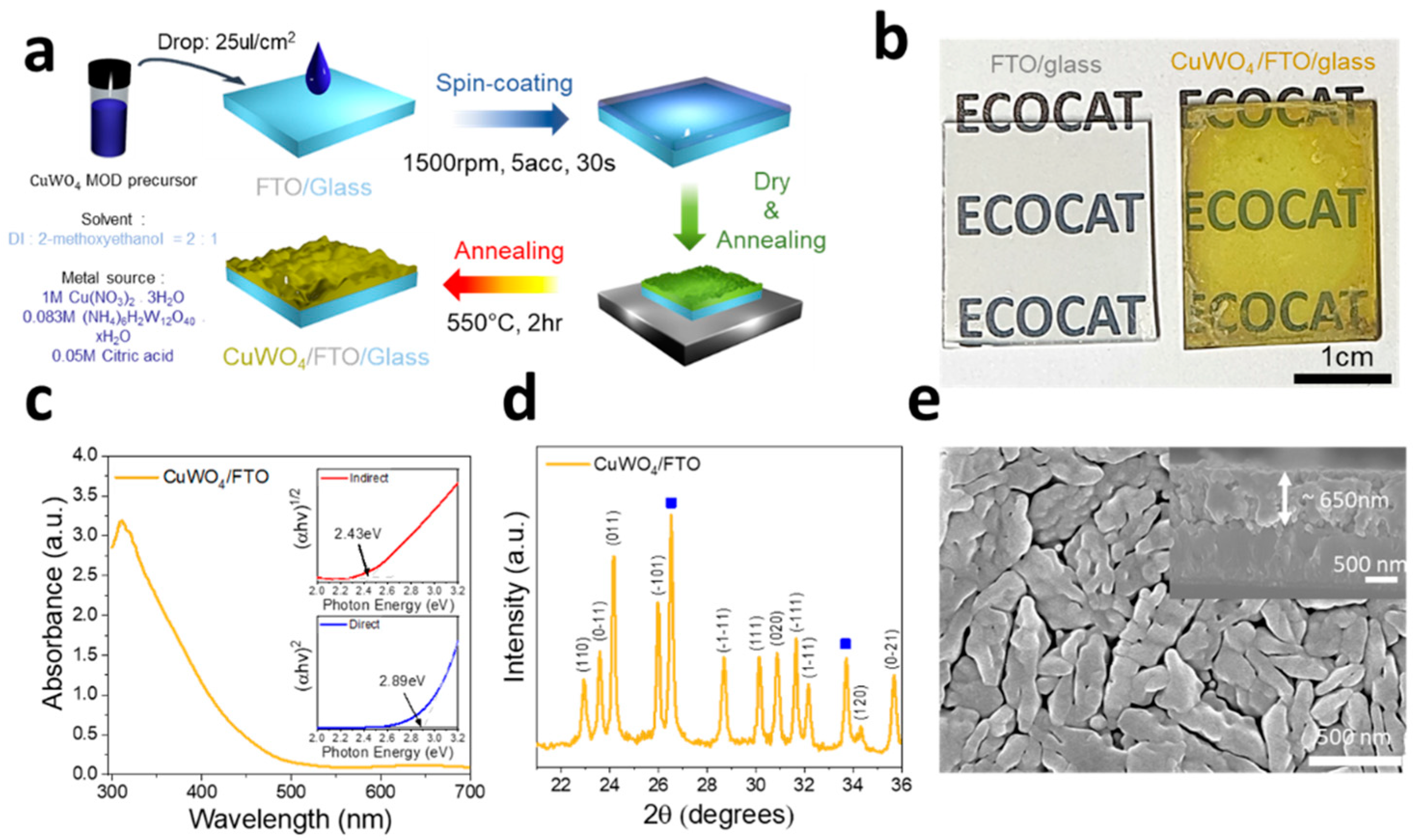
3.1. Synthesis of CuWO4 Thin Film

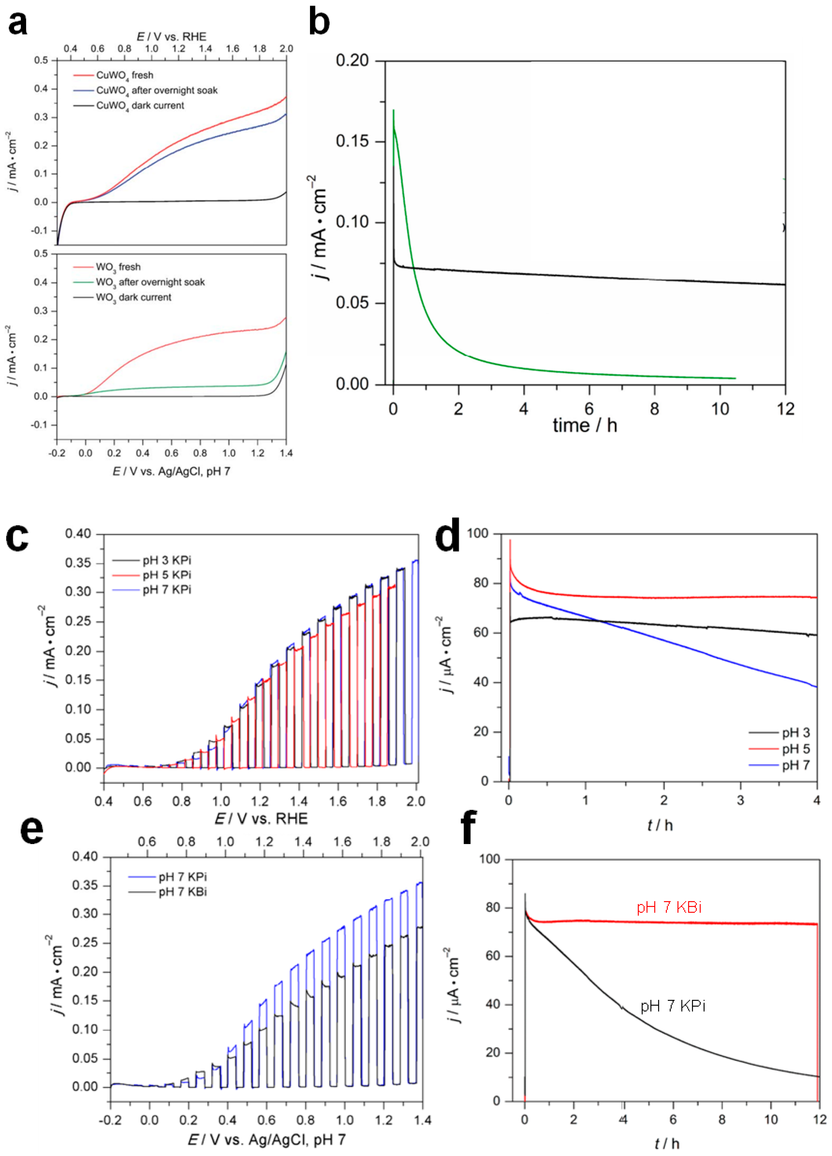
3.2. Stability of CuWO4

4. Photoelectrochemical Properties of CuWO4 Photoanodes
5. Modification Strategies of CuWO4 Photoanodes
5.1. Extrinsic/Intrinsic Defect Engineering via Doping


5.2. Formation of Solid Solution with Mo
5.3. Heterojunction Electron Transfer Layer
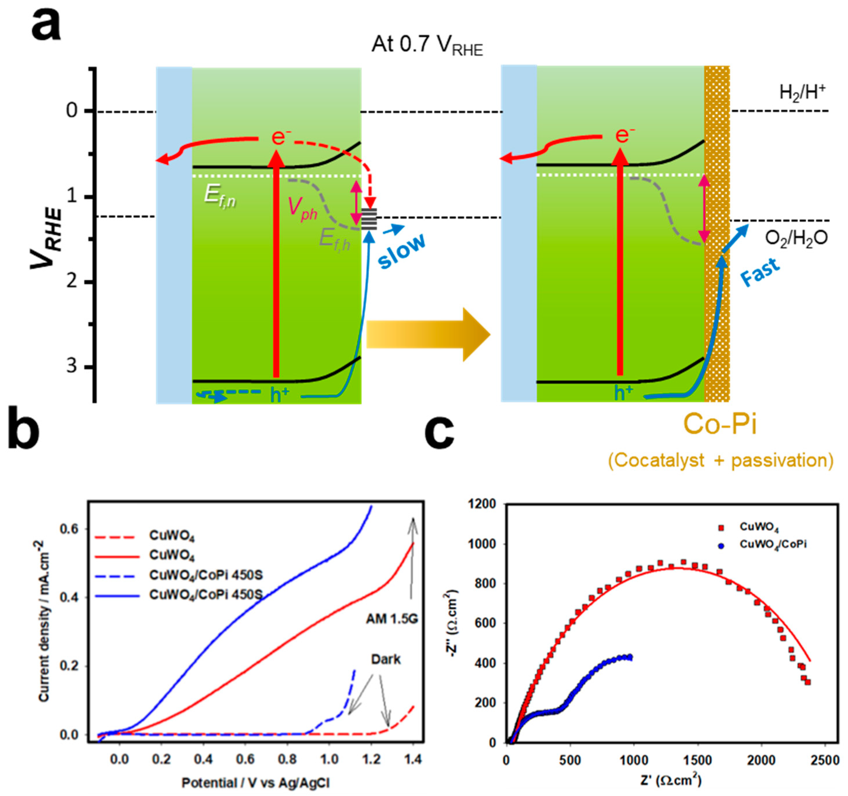
5.4. Surface Modification via Co-Catalyst Loading
6. Conclusions
Author Contributions
Funding
Data Availability Statement
Conflicts of Interest
References
- Davis, S.J.; Lewis, N.S.; Shaner, M.; Aggarwal, S.; Arent, D.; Azevedo, I.L.; Benson, S.M.; Bradley, T.; Brouwer, J.; Chiang, Y.-M.; et al. Net-zero emissions energy systems. Science 2018, 360, eaas9793. [Google Scholar] [CrossRef]
- Lewis, N.S. Research opportunities to advance solar energy utilization. Science 2016, 351, aad1920. [Google Scholar] [CrossRef]
- Jacobsson, T.J.; Fjällström, V.; Edoff, M.; Edvinsson, T. Sustainable solar hydrogen production: From photoelectrochemical cells to PV-electrolyzers and back again. Energy Environ. Sci. 2014, 7, 2056–2070. [Google Scholar] [CrossRef]
- Yao, T.; An, X.; Han, H.; Chen, J.Q.; Li, C. Photoelectrocatalytic materials for solar water splitting. Adv. Energy Mater. 2018, 8, 1800210. [Google Scholar] [CrossRef]
- Grätzel, M. Photoelectrochemical cells. Nature 2001, 414, 338–344. [Google Scholar] [CrossRef] [PubMed]
- Mesa, C.A.; Francas, L.; Yang, K.R.; Garrido-Barros, P.; Pastor, E.; Ma, Y.; Kafizas, A.; Rosser, T.E.; Mayer, M.T.; Reisner, E.; et al. Multihole water oxidation catalysis on haematite photoanodes revealed by operando spectroelectrochemistry and DFT. Nat. Chem. 2020, 12, 82–89. [Google Scholar] [CrossRef] [PubMed]
- Sivula, K.; Van De Krol, R. Semiconducting materials for photoelectrochemical energy conversion. Nat. Rev. Mater. 2016, 1, 15010. [Google Scholar] [CrossRef]
- Walter, M.G.; Warren, E.L.; McKone, J.R.; Boettcher, S.W.; Mi, Q.; Santori, E.A.; Lewis, N.S. Solar Water Splitting Cells. Chem. Rev. 2010, 110, 6446–6473. [Google Scholar] [CrossRef]
- Wang, Q.; Domen, K. Particulate Photocatalysts for Light-Driven Water Splitting: Mechanisms, Challenges, and Design Strategies. Chem. Rev. 2020, 120, 919–985. [Google Scholar] [CrossRef]
- Kudo, A.; Miseki, Y. Heterogeneous photocatalyst materials for water splitting. Chem. Soc. Rev. 2009, 38, 253–278. [Google Scholar] [CrossRef]
- Takata, T.; Jiang, J.; Sakata, Y.; Nakabayashi, M.; Shibata, N.; Nandal, V.; Seki, K.; Hisatomi, T.; Domen, K. Photocatalytic water splitting with a quantum efficiency of almost unity. Nature 2020, 581, 411–414. [Google Scholar] [CrossRef] [PubMed]
- Sarnowska, M.; Bienkowski, K.; Barczuk, P.J.; Solarska, R.; Augustynski, J. Highly Efficient and Stable Solar Water Splitting at (Na)WO3 Photoanodes in Acidic Electrolyte Assisted by Non-Noble Metal Oxygen Evolution Catalyst. Adv. Energy Mater. 2016, 6, 1600526. [Google Scholar] [CrossRef]
- Park, Y.; McDonald, K.J.; Choi, K.-S.J.C.S.R. Progress in bismuth vanadate photoanodes for use in solar water oxidation. Chem. Soc. Rev. 2013, 42, 2321–2337. [Google Scholar] [CrossRef] [PubMed]
- Hill, J.C.; Choi, K.-S. Synthesis and characterization of high surface area CuWO4 and Bi2WO6 electrodes for use as photoanodes for solar water oxidation. J. Mater. Chem. A 2013, 1, 5006–5014. [Google Scholar] [CrossRef]
- Bathula, B.; Eadi, S.B.; Lee, H.-D.; Yoo, K. ZnWO4 nanorod-colloidal SnO2 quantum dots core@shell heterostructures: Efficient solar-light-driven photocatalytic degradation of tetracycline. Environ. Res. 2023, 228, 115851. [Google Scholar] [CrossRef]
- Babu, B.; Peera, S.G.; Yoo, K. Fabrication of ZnWO4-SnO2 Core-Shell Nanorods for Enhanced Solar Light-Driven Photoelectrochemical Performance. Inorganics 2023, 11, 213. [Google Scholar] [CrossRef]
- Lhermitte, C.R.; Bartlett, B.M. Advancing the chemistry of CuWO4 for photoelectrochemical water oxidation. Acc. Chem. Res. 2016, 49, 1121–1129. [Google Scholar] [CrossRef]
- Tian, C.M.; Jiang, M.; Tang, D.; Qiao, L.; Xiao, H.Y.; Oropeza, F.; Hofmann, J.P.; Hensen, E.; Tadich, A.; Li, W.; et al. Elucidating the electronic structure of CuWO4 thin films for enhanced photoelectrochemical water splitting. J. Mater. Chem. A 2019, 7, 11895–11907. [Google Scholar] [CrossRef]
- Souza, E.L.S.; Sczancoski, J.C.; Nogueira, I.C.; Almeida, M.A.P.; Orlandi, M.O.; Li, M.S.; Luz, R.A.S.; Filho, M.G.R.; Longo, E.; Cavalcante, L.S. Structural evolution, growth mechanism and photoluminescence properties of CuWO4 nanocrystals. Ultrason. Sonochem. 2017, 38, 256–270. [Google Scholar] [CrossRef]
- Lalić, M.V.; Popović, Z.S.; Vukajlović, F.R. Ab initio study of electronic, magnetic and optical properties of CuWO4 tungstate. Comput. Mater. Sci. 2011, 50, 1179–1186. [Google Scholar] [CrossRef]
- Yourey, J.E.; Bartlett, B.M. Electrochemical deposition and photoelectrochemistry of CuWO4, a promising photoanode for water oxidation. J. Mater.Chem. 2011, 21, 7651–7660. [Google Scholar] [CrossRef]
- Lalić, M.V.; Popović, Z.S.; Vukajlović, F.R. Electronic structure and optical properties of CuWO4: An ab initio study. Comput. Mater. Sci. 2012, 63, 163–167. [Google Scholar] [CrossRef]
- Peeters, D.; Mendoza Reyes, O.; Mai, L.; Sadlo, A.; Cwik, S.; Rogalla, D.; Becker, H.W.; Schütz, H.M.; Hirst, J.; Müller, S.; et al. CVD-grown copper tungstate thin films for solar water splitting. J. Mater. Chem. A 2018, 6, 10206–10216. [Google Scholar] [CrossRef]
- Hu, D.; Diao, P.; Xu, D.; Xia, M.; Gu, Y.; Wu, Q.; Li, C.; Yang, S. Copper (II) tungstate nanoflake array films: Sacrificial template synthesis, hydrogen treatment, and their application as photoanodes in solar water splitting. Nanoscale 2016, 8, 5892–5901. [Google Scholar] [CrossRef] [PubMed]
- Zhang, Z.; Xiao, C.; Li, S. CuWO4 films grown via seeding-hydrothermal method for photoelectrochemical water oxidation. Mater. Lett. 2018, 232, 25–28. [Google Scholar] [CrossRef]
- Lee, J.U.; Kim, J.H.; Kang, K.; Shin, Y.S.; Kim, J.Y.; Kim, J.H.; Lee, J.S. Bulk and surface modified polycrystalline CuWO4 films for photoelectrochemical water oxidation. Renew. Energy 2023, 203, 779–787. [Google Scholar] [CrossRef]
- dos Santos Costa, M.J.; Lima, A.E.B.; Ribeiro, E.P.; dos Santos Costa, G.; Longo, E.; da Luz, G.E.; Cavalcante, L.S.; da Silva Santos , R. Transition metal tungstates AWO4 (A2+ = Fe, Co, Ni, and Cu) thin films and their photoelectrochemical behavior as photoanode for photocatalytic applications. J. Appl. Electrochem. 2023, 53, 1349–1367. [Google Scholar] [CrossRef]
- Duan, X.; Xu, C.; El Nahrawy, A.M.; Chen, J.; Zhu, Z.; Wang, J.; Liang, Q.; Cao, F. Ultrasonic Spray Pyrolysis-Assisted Fabrication of Ultrathin CuWO4 Films with Improved Photoelectrochemical Performance. ChemNanoMat 2022, 8, e202100419. [Google Scholar] [CrossRef]
- Gaillard, N.; Chang, Y.; DeAngelis, A.; Higgins, S.; Braun, A. A nanocomposite photoelectrode made of 2.2 eV band gap copper tungstate (CuWO4) and multi-wall carbon nanotubes for solar-assisted water splitting. Int. J. Hydrogen Energy 2013, 38, 3166–3176. [Google Scholar] [CrossRef]
- Gao, Y.; Zandi, O.; Hamann, T.W. Atomic layer stack deposition-annealing synthesis of CuWO4. J. Mater. Chem. A 2016, 4, 2826–2830. [Google Scholar] [CrossRef]
- Gonzalez, C.M.; Dunford, J.L.; Du, X.; Post, M.L. Characterization of carrier states in CuWO4 thin-films at elevated temperatures using conductometric analysis. J. Solid State Chem. 2013, 201, 35–40. [Google Scholar] [CrossRef]
- Hrubantova, A.; Hippler, R.; Wulff, H.; Cada, M.; Gedeon, O.; Jiricek, P.; Houdkova, J.; Olejnicek, J.; Nepomniashchaia, N.; Helm, C.A.; et al. Copper tungsten oxide (CuxWOy) thin films for optical and photoelectrochemical applications deposited by reactive high power impulse magnetron co-sputtering. J. Appl. Phys. 2022, 132, 215301. [Google Scholar] [CrossRef]
- Yourey, J.E.; Pyper, K.J.; Kurtz, J.B.; Bartlett, B.M. Chemical stability of CuWO4 for photoelectrochemical water oxidation. J. Phys. Chem. C 2013, 117, 8708–8718. [Google Scholar] [CrossRef]
- Wu, Z.; Zhao, Z.; Cheung, G.; Doughty, R.M.; Ballestas-Barrientos, A.R.; Hirmez, B.; Han, R.; Maschmeyer, T.; Osterloh, F.E. Role of Surface States in Photocatalytic Oxygen Evolution with CuWO4 Particles. J. Electrochem. Soc. 2019, 166, H3014. [Google Scholar] [CrossRef]
- Gao, Y.; Hamann, T.W. Elucidation of CuWO4 surface states during photoelectrochemical water oxidation. J. Phys. Chem. Lett. 2017, 8, 2700–2704. [Google Scholar] [CrossRef]
- Mayer, M.T. Photovoltage at semiconductor–electrolyte junctions. Curr. Opin. Electrochem. 2017, 2, 104–110. [Google Scholar] [CrossRef]
- Pyper, K.J.; Yourey, J.E.; Bartlett, B.M. Reactivity of CuWO4 in photoelectrochemical water oxidation is dictated by a midgap electronic state. J. Phys. Chem. C 2013, 117, 24726–24732. [Google Scholar] [CrossRef]
- Gao, Y.; Hamann, T.W. Quantitative hole collection for photoelectrochemical water oxidation with CuWO4. Chem. Commun. 2017, 53, 1285–1288. [Google Scholar] [CrossRef]
- Rodríguez-Gutiérrez, I.; Djatoubai, E.; Rodríguez-Pérez, M.; Su, J.; Rodríguez-Gattorno, G.; Vayssieres, L.; Oskam, G. Photoelectrochemical water oxidation at FTO|WO3@CuWO4 and FTO|WO3@CuWO4|BiVO4 heterojunction systems: An IMPS analysis. Electrochim. Acta 2019, 308, 317–327. [Google Scholar] [CrossRef]
- Peng, B.; Li, C.; Yue, C.; Diao, P. Sacrificial Template Synthesis of Copper Tungstate: Influence of Preparing Conditions on Morphology and Photoactivity. Int. J. Electrochem. Sci. 2019, 14, 2574–2588. [Google Scholar] [CrossRef]
- Bohra, D.; Smith, W.A. Improved charge separation via Fe-doping of copper tungstate photoanodes. Phys. Chem. Chem. Phys. 2015, 17, 9857–9866. [Google Scholar] [CrossRef] [PubMed]
- Li, C.; Diao, P. Fluorine doped copper tungsten nanoflakes with enhanced charge separation for efficient photoelectrochemical water oxidation. Electrochim. Acta 2020, 352, 136471. [Google Scholar] [CrossRef]
- González-Poggini, S.; Sánchez, B.; Colet-Lagrille, M. Enhanced Photoelectrochemical Activity of CuWO4 Photoanode by Yttrium Doping. J. Electrochem. Soc. 2023, 170, 066512. [Google Scholar] [CrossRef]
- Ikeue, K.; Ueno, T. Photoelectrochemical water oxidation properties of Mo-doped CuWO4: Effect of p-type sulfide loading and annealing. Mater. Lett. 2023, 348, 134690. [Google Scholar] [CrossRef]
- Hill, J.C.; Ping, Y.; Galli, G.A.; Choi, K.-S. Synthesis, photoelectrochemical properties, and first principles study of n-type CuW1−xMoxO4 electrodes showing enhanced visible light absorption. Energy Environ. Sci 2013, 6, 2440–2446. [Google Scholar] [CrossRef]
- Liang, Q.; Guo, Y.; Zhang, N.; Qian, Q.; Hu, Y.; Hu, J.; Li, Z.; Zou, Z. Improved water-splitting performances of CuW1−xMoxO4 photoanodes synthesized by spray pyrolysis. Sci. China Mater. 2018, 61, 1297–1304. [Google Scholar] [CrossRef]
- Yang, J.; Li, C.; Diao, P. Molybdenum doped CuWO4 nanoflake array films as an efficient photoanode for solar water splitting. Electrochim. Acta 2019, 308, 195–205. [Google Scholar] [CrossRef]
- Polo, A.; Nomellini, C.; Grigioni, I.; Dozzi, M.V.; Selli, E. Effective Visible Light Exploitation by Copper Molybdo-Tungstate Photoanodes. ACS Appl. Energy Mater. 2020, 3, 6956–6964. [Google Scholar] [CrossRef]
- Wang, D.; Bassi, P.S.; Qi, H.; Zhao, X.; Gurudayal; Wong, L.H.; Xu, R.; Sritharan, T.; Chen, Z. Improved Charge Separation in WO3/CuWO4 Composite Photoanodes for Photoelectrochemical Water Oxidation. Materials 2016, 9, 348. [Google Scholar] [CrossRef]
- Wang, T.; Fan, X.; Gao, B.; Jiang, C.; Li, Y.; Li, P.; Zhang, S.; Huang, X.; He, J. Self-Assembled Urchin-like CuWO4/WO3 Heterojunction Nanoarrays as Photoanodes for Photoelectrochemical Water Splitting. ChemElectroChem 2021, 8, 125–134. [Google Scholar] [CrossRef]
- Ye, W.; Chen, F.; Zhao, F.; Han, N.; Li, Y. CuWO4 nanoflake array-based single-junction and heterojunction photoanodes for photoelectrochemical water oxidation. ACS Appl. Mater. Interfaces 2016, 8, 9211–9217. [Google Scholar] [CrossRef]
- Chen, S.; Hossain, M.N.; Chen, A. Significant enhancement of the photoelectrochemical activity of CuWO4 by using a cobalt phosphate nanoscale thin film. ChemElectroChem 2018, 5, 523–530. [Google Scholar] [CrossRef]
- Li, C.; Guo, B.; Peng, B.; Yue, C.; Diao, P. Copper Tungstate (CuWO4) Nanoflakes Coupled with Cobalt Phosphate (Co-Pi) for Effective Photoelectrochemical Water Splitting. Int. J. Electrochem. Sci. 2019, 14, 9017–9029. [Google Scholar] [CrossRef]
- Rosa, W.S.; Rabelo, L.G.; Tiveron Zampaulo, L.G.; Gonçalves, R.V. Ternary Oxide CuWO4/BiVO4/FeCoOx Films for Photoelectrochemical Water Oxidation: Insights into the Electronic Structure and Interfacial Band Alignment. ACS Appl. Mater. Interfaces 2022, 14, 22858–22869. [Google Scholar] [CrossRef] [PubMed]
- Nam, K.M.; Cheon, E.A.; Shin, W.J.; Bard, A.J. Improved Photoelectrochemical Water Oxidation by the WO3/CuWO4 Composite with a Manganese Phosphate Electrocatalyst. Langmuir 2015, 31, 10897–10903. [Google Scholar] [CrossRef] [PubMed]
- Fan, L.; Sunarso, J.; Zhang, X.; Xiong, X.; He, L.; Luo, L.; Wang, F.; Fan, Z.; Wu, C.; Han, D.; et al. Regulating the hole transfer from CuWO4 photoanode to NiWO4 electrocatalyst for enhanced water oxidation performance. Int. J. Hydrogen Energy 2022, 47, 20153–20165. [Google Scholar] [CrossRef]
- Shadabipour, P.; Raithel, A.L.; Hamann, T.W. Charge-Carrier Dynamics at the CuWO4/Electrocatalyst Interface for Photoelectrochemical Water Oxidation. ACS Appl. Mater. Interfaces 2020, 12, 50592–50599. [Google Scholar] [CrossRef]
- Davi, M.; Mann, M.; Ma, Z.; Schrader, F.; Drichel, A.; Budnyk, S.; Rokicinska, A.; Kustrowski, P.; Dronskowski, R.; Slabon, A. An MnNCN-Derived Electrocatalyst for CuWO4 Photoanodes. Langmuir 2018, 34, 3845–3852. [Google Scholar] [CrossRef]
- Xiong, X.; Fan, L.; Chen, G.; Wang, Y.; Wu, C.; Chen, D.; Lin, Y.; Li, T.; Fu, S.; Ren, S. Boosting water oxidation performance of CuWO4 photoanode by surface modification of nickel phosphate. Electrochim. Acta 2019, 328, 135125. [Google Scholar] [CrossRef]
- Salimi, R.; Sabbagh Alvani, A.A.; Mei, B.T.; Naseri, N.; Du, S.F.; Mul, G. Ag-Functionalized CuWO4/WO3 nanocomposites for solar water splitting. New J. Chem. 2019, 43, 2196–2203. [Google Scholar] [CrossRef]
- Li, C.; Diao, P. Boosting the Activity and Stability of Copper Tungsten Nanoflakes toward Solar Water Oxidation by Iridium-Cobalt Phosphates Modification. Catalysts 2020, 10, 913. [Google Scholar] [CrossRef]
- Tang, Y.; Rong, N.; Liu, F.; Chu, M.; Dong, H.; Zhang, Y.; Xiao, P. Enhancement of the photoelectrochemical performance of CuWO4 films for water splitting by hydrogen treatment. Appl. Surf. Sci 2016, 361, 133–140. [Google Scholar] [CrossRef]
- Ma, Z.; Linnenberg, O.; Rokicinska, A.; Kustrowski, P.; Slabon, A. Augmenting the Photocurrent of CuWO4 Photoanodes by Heat Treatment in the Nitrogen Atmosphere. J. Phys. Chem. C 2018, 122, 19281–19288. [Google Scholar] [CrossRef]
- Wang, K.; Chen, L.; Liu, X.; Li, J.; Liu, Y.; Liu, M.; Qiu, X.; Li, W. Gradient surficial forward Ni and interior reversed Mo-doped CuWO4 films for enhanced photoelectrochemical water splitting. Chem. Eng. J. 2023, 471, 144730. [Google Scholar] [CrossRef]
- Kim, J.H.; Lee, J.S. Elaborately modified BiVO4 photoanodes for solar water splitting. Adv. Mater. 2019, 31, 1806938. [Google Scholar] [CrossRef] [PubMed]
- Sivula, K.; Formal, F.L.; Grätzel, M. WO3-Fe2O3 Photoanodes for Water Splitting: A Host Scaffold, Guest Absorber Approach. Chem. Mater. 2009, 21, 2862–2867. [Google Scholar] [CrossRef]
- Shi, X.; Zhang, K.; Shin, K.; Ma, M.; Kwon, J.; Choi, I.T.; Kim, J.K.; Kim, H.K.; Wang, D.H.; Park, J.H. Unassisted photoelectrochemical water splitting beyond 5.7% solar-to-hydrogen conversion efficiency by a wireless monolithic photoanode/dye-sensitised solar cell tandem device. Nano Energy 2015, 13, 182–191. [Google Scholar] [CrossRef]
- Bignozzi, C.A.; Caramori, S.; Cristino, V.; Argazzi, R.; Meda, L.; Tacca, A. Nanostructured photoelectrodes based on WO3: Applications to photooxidation of aqueous electrolytes. Chem. Soc. Rev. 2013, 42, 2228–2246. [Google Scholar] [CrossRef]
- Wang, D.; Li, R.; Zhu, J.; Shi, J.; Han, J.; Zong, X.; Li, C. Photocatalytic Water Oxidation on BiVO4 with the Electrocatalyst as an Oxidation Cocatalyst: Essential Relations between Electrocatalyst and Photocatalyst. J. Phys. Chem. C 2012, 116, 5082–5089. [Google Scholar] [CrossRef]
- Nellist, M.R.; Qiu, J.; Laskowski, F.A.; Toma, F.M.; Boettcher, S.W. Potential-sensing electrochemical AFM shows CoPi as a hole collector and oxygen evolution catalyst on BiVO4 water-splitting photoanodes. ACS Energy Lett. 2018, 3, 2286–2291. [Google Scholar] [CrossRef]


| Strategies | Reported Substances | Typical Effects |
|---|---|---|
| Synthesis method | Electrodeposition [14,21] Thermal conversion [39,40] Sol–gel method [26,29,35] Hydrothermal [25] | Electrodeposition (Jph 0.2 mA/cm2 at 1.23 VRHE) [21] |
| ALD [30] | Thermal conversion (Jph 0.33 mA/cm2 at 1.23 VRHE) [24] | |
| CVD [23] Ultrasonic spray pyrolysis [28] Impulse magnetron co-sputtering [32] PLD [31] | Sol–gel (Jph 0.5mA/cm2 at 1.23 VRHE, 1.0 mA/cm2 at 1.23 VRHE for SA oxidation) [18] Sol–gel (Jph 0.07mA/cm2 at 1.23 VRHE, 0.15 mA/cm2 at 1.23 VRHE for SA oxidation) [26] | |
| Doping | Fe3+ [41] | 0.3% Fe:CuWO4/FTO, ~1.5 times greater ηbulk (Jph 0.5 mA/cm2 at 1.23 VRHE for SA oxidation) [41] |
| F [42] Y3+ [43] Mo6+ [44] | ||
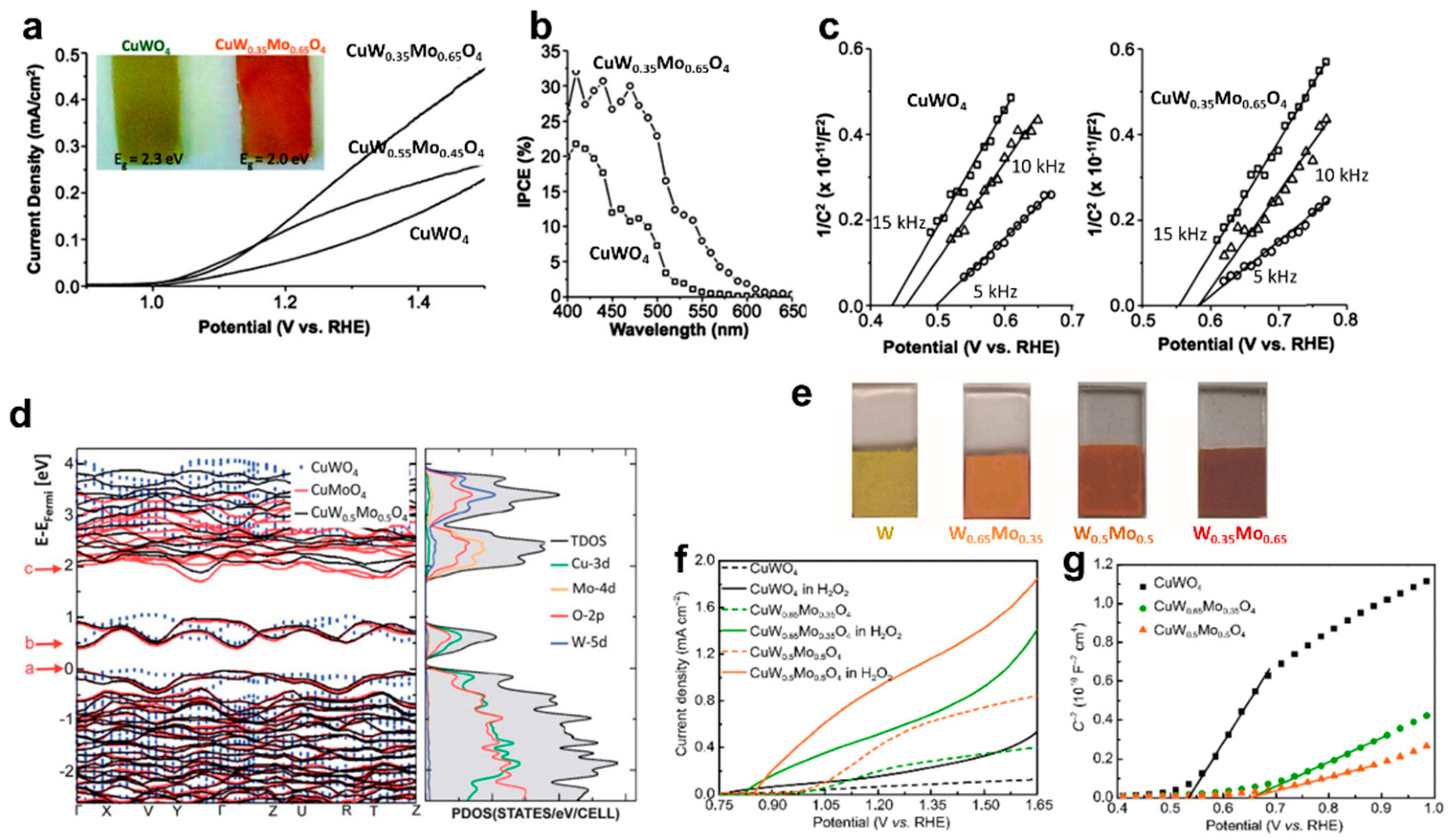
| Mo solid solution | Mo6+ [45,46,47,48] | Red shift of photoresponse (from 550 nm to 600 nm) [45] CuW0.35Mo0.65O4/FTO (Jph 1.0 mA/cm2 at 1.23 VRHE for SA oxidation) [46] |
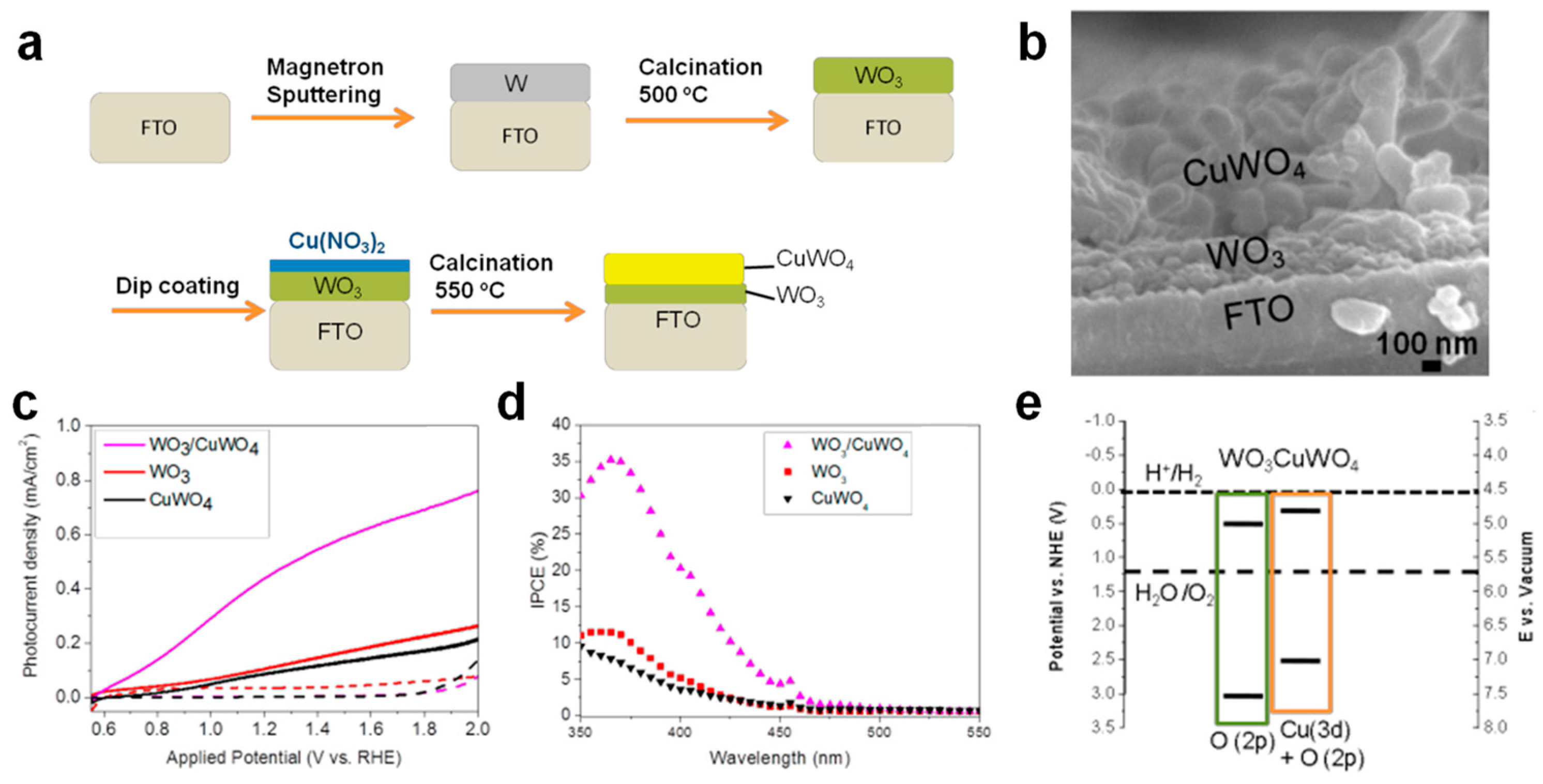
| Heterojunction and electron transfer layer | WO3 (flat) [49] WO3 (nanorod) [39] WO3 (urchin like) [50] SnO2 [26] BiVO4 [51] | CuWO4/flat WO3/FTO. ~4 times increment (Jph 0.55 mA/cm2 at 1.23 VRHE) [49] |
| Electrocatalyst | Co-Pi [26,52,53] Co3O4 [18] FeCoOx [54] MnPO4 [55] NiWO4 [56] NiFeOx [57] P-type sulfide (MoS2, NbS2, NiSx) [44] MnNCN [58] Ni-Pi [59] Ag [60] | Co-Pi/CuWO4/FTO, 30% increment (Jph 0.4 mA/cm2 at 0.6 VAg/AgCl) [52] |
| IrCo-Pi [61] | ||
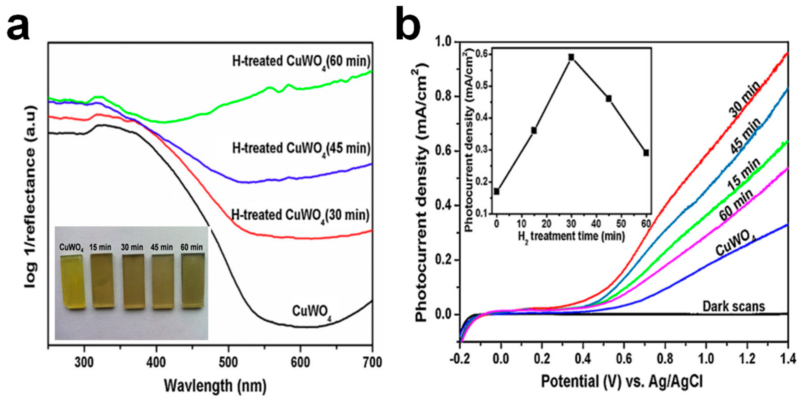
| Post-treatment | H2 treatment [62] | H2 treatment (300 °C), 3-time increment (Jph 0.6 mA/cm2 at 1.01 VAg/AgCl) [62] |
Disclaimer/Publisher’s Note: The statements, opinions and data contained in all publications are solely those of the individual author(s) and contributor(s) and not of MDPI and/or the editor(s). MDPI and/or the editor(s) disclaim responsibility for any injury to people or property resulting from any ideas, methods, instructions or products referred to in the content. |
© 2023 by the authors. Licensee MDPI, Basel, Switzerland. This article is an open access article distributed under the terms and conditions of the Creative Commons Attribution (CC BY) license (https://creativecommons.org/licenses/by/4.0/).
Share and Cite
Lee, J.U.; Kim, J.H.; Lee, J.S. Emergent CuWO4 Photoanodes for Solar Fuel Production: Recent Progress and Perspectives. Catalysts 2023, 13, 1408. https://doi.org/10.3390/catal13111408
Lee JU, Kim JH, Lee JS. Emergent CuWO4 Photoanodes for Solar Fuel Production: Recent Progress and Perspectives. Catalysts. 2023; 13(11):1408. https://doi.org/10.3390/catal13111408
Chicago/Turabian StyleLee, Jin Uk, Jin Hyun Kim, and Jae Sung Lee. 2023. "Emergent CuWO4 Photoanodes for Solar Fuel Production: Recent Progress and Perspectives" Catalysts 13, no. 11: 1408. https://doi.org/10.3390/catal13111408