
ZnO Particles Stabilized in Polymeric Matrix for Liquid-Phase Methanol Synthesis
 , ,
, ,
Abstract
:1. Introduction
2. Results and Discussion
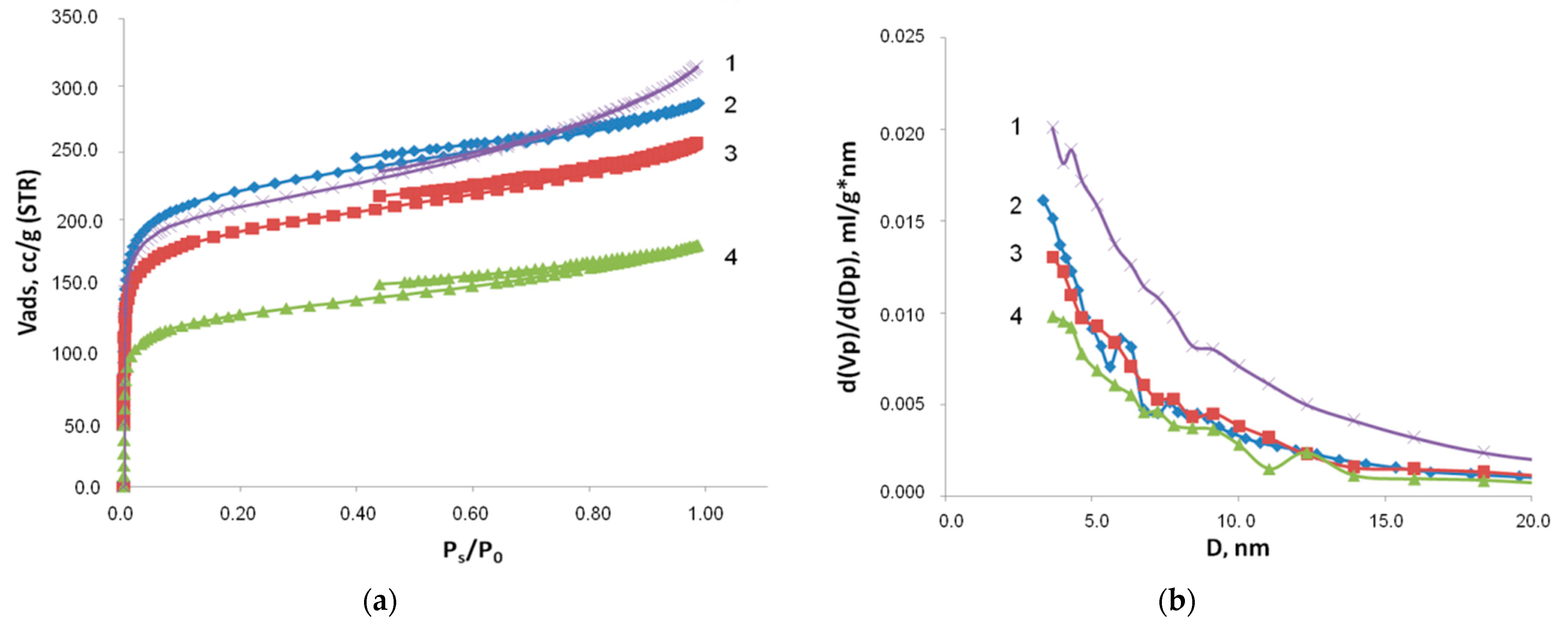
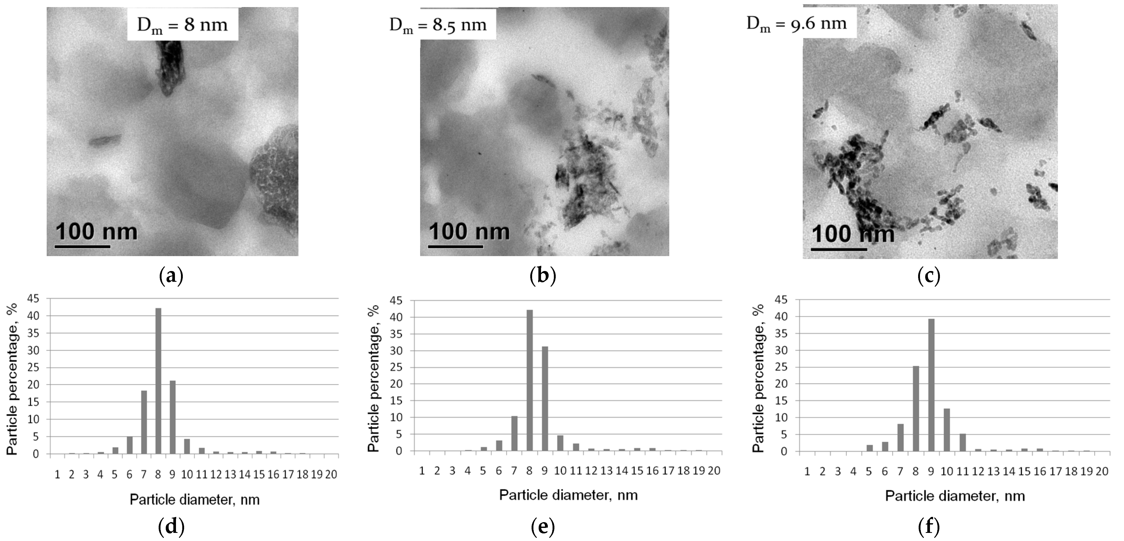
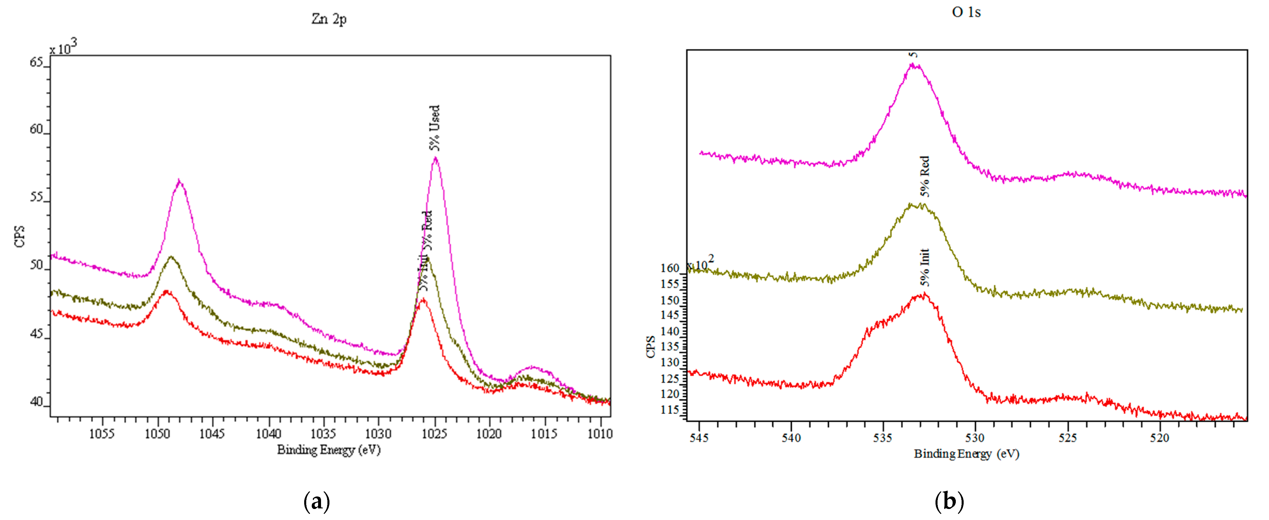
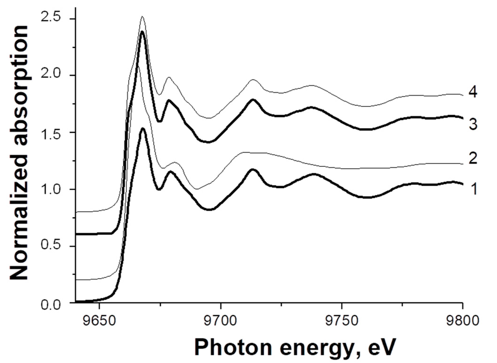
2.1. Characterization of Catalyst Samples
2.2. Catalytic Performance Study
3. Materials and Methods
3.1. Materials
3.2. ZnO Catalyst Synthesis
3.3. Catalyst Characterization
3.4. Catalytic Performance Study
4. Conclusions
Supplementary Materials
Author Contributions
Funding
Data Availability Statement
Conflicts of Interest
References
- Farsi, M.; Jahanmiri, A. Application of water vapor-permselective alumina–silica composite membrane in methanol synthesis process to enhance CO2 hydrogenation and catalyst life time. J. Ind. Eng. Chem. 2012, 18, 1088–1095. [Google Scholar] [CrossRef]
- Olah, G.A. Towards Oil Independence Through Renewable Methanol Chemistry. Angew. Chem. Int. Ed. 2012, 52, 104–107. [Google Scholar] [CrossRef] [PubMed]
- Choudhury, J. New Strategies for CO2-to-Methanol Conversion. ChemCatChem 2012, 4, 609–611. [Google Scholar] [CrossRef]
- Din, I.U.; Shaharun, M.S.; Alotaibi, M.A.; Alharthi, A.I.; Naeem, A. Recent developments on heterogeneous catalytic CO2 reduction to methanol. J. CO2 Util. 2019, 34, 20–33. [Google Scholar] [CrossRef]
- Gautam, P.; Upadhyay, S.N.; Dubey, S.K. Bio-methanol as a renewable fuel from waste biomass: Current trends and future perspective. Fuel 2020, 273, 117783. [Google Scholar] [CrossRef]
- Detchusananard, T.; Prasertcharoensuk, P.; Patcharavorachot, Y.; Maréchal, F.; Arpornwichanop, A. Exergy and exergoeconomic assessment of sustainable light olefins production from an integrated methanol synthesis and methanol-to-olefins system. J. Clean. Prod. 2022, 347, 131209. [Google Scholar] [CrossRef]
- Im-orb, K.; Arpornwichanop, A. Process and sustainability analyses of the integrated biomass pyrolysis, gasification, and methanol synthesis process for methanol production. Energy 2020, 193, 116788. [Google Scholar] [CrossRef]
- Olah, G.A.; Prakash, G.K.S. Efficient and Selective Conversion of Carbon Dioxide to Methanol, Dimethyl Ether and Derived Products. Patent EP1871731B1, 26 December 2012. [Google Scholar]
- Christiansen, J.A. Method of Producing Methyl Alcohol from Alkyl Formate. U.S. Patent No 1,302-011, 29 April 1919. [Google Scholar]
- Olah, G.A.; Gupta, B.; Farina, M. Selective monohalogenation of methane over supported acid or platinum metal catalysts and hydrolysis of methyl halides over gamma-alumina-supported metal oxide/hydroxide catalysts. A feasible path for the oxidative conversion of methane into methyl alcohol/dimethyl ether. J. Am. Chem. Soc. 1985, 107, 7097–7105. [Google Scholar]
- Deutschmann, O.; Knozinger, H.; Kochloefl, K.; Turek, T. Heterogneous Catalysis and Solid Catalysts; Wiley-VCH Verlag GmhH & Co. KGaA: Weinheim, Germany, 2009; pp. 82–93. [Google Scholar]
- Li, Y.; Sorribes, I.; Yan, T.; Junge, K.; Beller, M. Selective methylation of amines with carbon dioxide and H2. Angew. Chem. 2013, 52, 12156–12160. [Google Scholar] [CrossRef]
- Li, C.; Yuan, X.; Fujimoto, K. Development of highly stable catalyst for methanol synthesis from carbon dioxide. Appl. Catal. A Gen. 2014, 469, 306–311. [Google Scholar] [CrossRef]
- Karelovic, A.; Ruiz, P. The role of copper particle size in low pressure methanol synthesis via CO2 hydrogenation over Cu/ZnO catalysts. Catal. Sci. Technol. 2015, 5, 869–881. [Google Scholar] [CrossRef]
- Pinto, A.; Rogerson, P.L. Impact of high fuel cost on plant design. Chem. Eng. Prog. 1977, 73, 95–100. [Google Scholar]
- Haid, J.; Koss, U. Lurgi’s Mega-Methanol technology opens the door for a new era in down-stream applications. Stud. Surf. Sci. Catal. 2001, 136, 399–404. [Google Scholar]
- Takase, I.; Niwa, K. Mitsubishi (MGC/MHI) methanol process CEER. Chem. Econ. Eng. Rev. 1985, 17, 24–30. [Google Scholar]
- Fiedler, E.; Grossmann, G.; Kersebohm, D.B.; Weiss, G.; Witte, C. Methanol. In Ullmann’s Encyclopedia of Industrial Chemistry Release, 6th ed.; Wiley-VCH, Verlag GmbH & Co. KGaA: Weinheim, Germany, 2003; pp. 1–23. [Google Scholar]
- Wang, J.; Anthony, R.G.; Akgerman, A. Mathematical simulations of the performance of trickle bed and slurry reactors for methanol synthesis. Comput. Chem. Eng. 2005, 29, 2474–2484. [Google Scholar] [CrossRef]
- Heydorn, E.C.; Diamond, B.W.; Lilly, R.D. Commercial-Scale Demonstration of the Liquid Phase Methanol (LPMEOH_) Process: Final Report; Air Products Liquid Phase Conversion Company for the US DOE National Energy Technology Laboratory: Allentown, PA, USA, 2003.
- Nassirpour, M.; Khademi, M.H. Evaluation of different cooling technologies for industrial methanol synthesis reactor in terms of energy efficiency and methanol yield: An economic-optimization. J. Taiwan Inst. Chem. Eng. 2020, 113, 302–314. [Google Scholar] [CrossRef]
- Van der Laan, G.P.; Beenackers, A.A.C.M.; Ding, B.; Strikwerda, J.C. Liquid-phase methanol synthesis in apolar (squalane) and polar (tetraethylene glycol dimethylether) solvents. Catal. Today 1999, 48, 93–100. [Google Scholar] [CrossRef]
- Schimpf, S.; Rittermeier, A.; Zhang, X.; Li, Z.-A.; Spasova, M.; van den Berg, M.W.E.; Farle, M.; Wang, Y.; Fischer, R.A.; Muhler, M. Stearate-Based Cu Colloids in Methanol Synthesis: Structural Changes Driven by Strong Metal–Support Interactions. ChemCatChem 2010, 2, 214–222. [Google Scholar] [CrossRef]
- Zhang, X.; Zhong, L.; Guo, Q.; Fan, H.; Zheng, H.; Xie, K. Influence of the calcination on the activity and stability of the Cu/ZnO/Al2O3 catalyst in liquid phase methanol synthesis. Fuel 2010, 89, 1348–1352. [Google Scholar] [CrossRef]
- Mabuse, H.; Hagihara, K.; Watanabe, T.; Saito, M. Liquid phase methanol synthesis catalyst. Energy Convers. Manag. 1997, 38, S437–S442. [Google Scholar] [CrossRef]
- Meesattham, S.; Kim-Lohsoontorn, P. Low-temperature alcohol-assisted methanol synthesis from CO2 and H2: The effect of alcohol type. Int. J. Hydrog. Energy 2022, 47, 22691–22703. [Google Scholar] [CrossRef]
- Kriprasertkul, W.; Witoon, T.; Kim-Lohsoontorn, P. Dimethyl ether (DME) synthesis from CO2 and H2 through ethanol-assisted methanol synthesis and methanol dehydration. Int. J. Hydrog. Energy 2022, 47, 33338–33351. [Google Scholar] [CrossRef]
- Boonamnuay, T.; Laosiripojana, N.; Assabumrungrat, S.; Kim-Lohsoontorn, P. Effect 3A and 5A molecular sieve on alcohol-assisted methanol synthesis from CO2 and H2 over Cu/ZnO catalyst. Int. J. Hydrog. Energy 2021, 46, 30948–30958. [Google Scholar] [CrossRef]
- Kung, H.H. Deactivation of methanol synthesis catalysts—A review. Catal. Today 1992, 11, 443–453. [Google Scholar] [CrossRef]
- Lee, S. Methanol Synthesis Technology; CRC Press: Boca Raton, FL, USA, 1990. [Google Scholar]
- Klier, K.; Chatikavanij, V.; Herman, R.G.; Simmons, G.W. Catalytic synthesis of methanol from CO/H2: IV. The effects of carbon dioxide. J. Catal. 1982, 74, 343–360. [Google Scholar] [CrossRef]
- Cazelles, R.; Drone, J.; Fajula, F.; Ersen, O.; Moldovan, S.; Galarneau, A. Reduction of CO2 to methanol by a polyenzymatic system encapsulated in phospholipids–silica nanocapsules. New J. Chem. 2013, 37, 3721–3730. [Google Scholar] [CrossRef]
- Frei, E.; Schaadt, A.; Ludwig, T.; Hillebrecht, H.; Krossing, I. The Influence of the Precipitation/Ageing Temperature on a Cu/ZnO/ZrO2 Catalyst for Methanol Synthesis from H2 and CO2. ChemCatChem 2014, 6, 1721–1730. [Google Scholar] [CrossRef]
- Gao, P.; Li, F.; Zhan, H.; Zhao, N.; Xiao, F.; Wei, W.; Zhong, L.; Sun, Y. Fluorine-modified Cu/Zn/Al/Zr catalysts via hydrotalcite-like precursors for CO2 hydrogenation to methanol. Catal. Commun. 2014, 50, 78–82. [Google Scholar] [CrossRef]
- Santiago, M.; Barbera, K.; Ferreira, C.; Curulla-Ferré, D.; Kolb, P.; Pérez-Ramírez, J. By-product co-feeding reveals insights into the role of zinc on methanol synthesis catalysts. Catal. Commun. 2012, 21, 63–67. [Google Scholar] [CrossRef]
- Akbarzadeh, H.; Abbaspour, M.; Salemi, S. Carbon monoxide adsorption on the single-walled carbon nanotube supported gold–silver nanoalloys. New J. Chem. 2016, 40, 310–319. [Google Scholar] [CrossRef]
- Yang, H.; Gao, P.; Zhang, C.; Zhong, L.; Li, X.; Wang, S.; Wang, H.; Wei, W.; Sun, Y. Core–shell structured Cu@m-SiO2 and Cu/ZnO@m-SiO2 catalysts for methanol synthesis from CO2 hydrogenation. Catal. Commun. 2016, 84, 56–60. [Google Scholar] [CrossRef]
- Kaluza, S.; Behrens, M.; Schiefenhövel, N.; Kniep, B.; Fischer, R.; Schlögl, R.; Muhler, M. A Novel Synthesis Route for Cu/ZnO/Al2O3 Catalysts used in Methanol Synthesis: Combining Continuous Consecutive Precipitation with Continuous Aging of the Precipitate. ChemCatChem 2011, 3, 189–199. [Google Scholar] [CrossRef]
- Zhang, P.; Araki, Y.; Feng, X.; Li, H.; Fang, Y.; Chen, F.; Shi, L.; Peng, X.; Yoneyama, Y.; Yang, G.; et al. Urea-derived Cu/ZnO catalyst being dried by supercritical CO2 for low-temperature methanol synthesis. Fuel 2020, 268, 117213. [Google Scholar] [CrossRef]
- Ay, S.; Ozdemir, M.; Melikoglu, M. Effects of metal promotion on the performance, catalytic activity, selectivity and deactivation rates of Cu/ZnO/Al2O3 catalysts for methanol synthesis. Chem. Eng. Res. Des. 2021, 175, 146–160. [Google Scholar] [CrossRef]
- Spath, P.L.; Dayton, D.C. Preliminary Screening—Technical and Economic Assessment of Synthesis Gas to Fuels and Chemicals with Emphasis on the Potential for Biomass-Derived Syngas. Available online: wwwnrelgov/docs/fy04osti/34929pdf (accessed on 20 September 2022).
- Chen, F.; Gao, W.; Wang, K.; Wang, C.; Wu, X.; Liu, N.; Guo, X.; He, Y.; Zhang, P.; Yang, G.; et al. Enhanced performance and stability of Cu/ZnO catalyst by introducing MgO for low-temperature methanol synthesis using methanol itself as a catalytic promote. Fuel 2022, 315, 123272. [Google Scholar] [CrossRef]
- Wernicke, H.-J.; Plass, L.; Schmidt, F. Methanol generation. In Methanol: The Basic Chemical and Energy Feedstock of the Future; Bertau, M., Offermanns, H., Plass, L., Schmidt, F., Wernicke, H.-J., Eds.; Springer: Berlin/Heidelberg, Germany, 2014; pp. 51–300. [Google Scholar]
- Poto, S.; van Berkel, D.V.; Gallucci, F.; d’Angelo, M.F.N. Kinetic modeling of the methanol synthesis from CO2 and H2 over a CuO/CeO2/ZrO2 catalyst: The role of CO2 and CO hydrogenation. Chem. Eng. J. 2022, 435, 134946. [Google Scholar] [CrossRef]
- Li, Z.; Du, T.; Li, Y.; Jia, H.; Wang, Y.; Song, Y.; Fang, X. Water- and reduction-free preparation of oxygen vacancy rich Cu-ZnO-ZrO2 catalysts for promoted methanol synthesis from CO2. Fuel 2022, 322, 124264. [Google Scholar] [CrossRef]
- Ovesen, C.V. Kinetic Modeling of Reactions on Cu Surfaces. Ph.D. Thesis, Laboratory of Applied Physics, Technical University of Denmark, Lyngby, Denmark, 1992. [Google Scholar]
- Clausen, B.S.; Steffensen, G.; Fabius, B.; Villadsen, J.; Feidenhans’l, R.; Topsoe, H. In situ cell for combined XRD and on-line catalysis tests: Studies of Cu-based water gas shift and methanol catalysts. J. Catal. 1991, 132, 524–535. [Google Scholar] [CrossRef]
- Fujitani, T.; Nakamura, J. The chemical modification seen in the Cu/ZnO methanol synthesis catalysts. Appl. Catal. A Gen. 2000, 191, 111–129. [Google Scholar] [CrossRef]
- Ostrovskii, V.E. Mechanisms of methanol synthesis from hydrogen and carbon oxides at Cu–Zn-containing catalysts in the context of some fundamental problems of heterogeneous catalysis. Catal. Today 2002, 77, 141–160. [Google Scholar] [CrossRef]
- Doluda, V.Y.; Sulman, E.M.; Matveeva, V.G.; Sulman, M.G.; Bykov, A.V.; Lakina, N.V.; Sidorov, A.I.; Valetsky, P.M.; Bronstein, L.M. Phenol Catalytic Wet Air Oxidation Over Ru Nanoparticles Formed in Hypercrosslinked Polystyrene. Top. Catal. 2013, 56, 688–695. [Google Scholar] [CrossRef]
- Manaenkov, O.V.; Matveeva, V.G.; Sulman, E.M.; Filatova, A.E.; Makeeva, O.Y.; Kislitza, O.V.; Sidorov, A.I.; Doluda, V.Y.; Sulman, M.G. Ru-Containing Polymeric Catalysts for Cellulose Conversion to Polyols. Top. Catal. 2014, 57, 1476–1482. [Google Scholar] [CrossRef]
- Sapunov, V.N.; Stepacheva, A.A.; Sulman, E.M.; Warna, J.; Maki-Arvela, P.; Sulman, M.G.; Sidorov, A.I.; Stein, B.D.; Murzin, D.Y.; Matveeva, V.G. Stearic acid hydrodeoxygenation over Pd nanoparticles embedded in mesoporous hypercrosslinked polystyrene. J. Ind. Eng. Chem. 2017, 46, 426–435. [Google Scholar] [CrossRef]
- Thommes, M.; Kaneko, K.; Neimark, A.V.; Olivier, J.P.; Rodriguez-Reinoso, F.; Rouquerol, J.; Sing, K.S. Physisorption of Gases, with Special Reference to the Evaluation of Surface Area and Pore Size Distribution (IUPAC Technical Report). Pure Appl. Chem. 2015, 87, 1051–1069. [Google Scholar] [CrossRef]
- Guo, H.-L.; Zhu, Q.; Wu, X.-L.; Jiang, Y.-F.; Xie, X.; Xu, A.-W. Oxygen deficient ZnO1−x nanosheets with high visible light photocatalytic activity. Nanoscale 2015, 7, 7216–7223. [Google Scholar] [CrossRef] [PubMed]
- Armelao, L.; Barreca, D.; Bottaro, G. ZnO:Er(III) Nanosystems Analyzed by XPS. Surf. Sci. Spectra 2006, 13, 9–16. [Google Scholar] [CrossRef]
- Pauly, N.; Yubero, F.; Espinós, J.P.; Tougaard, S. XPS primary excitation spectra of Zn 2p, Fe 2p, and Ce 3d from ZnO, α-Fe2O3, and CeO2. Surface Interface Anal. 2018, 51, 353–360. [Google Scholar] [CrossRef]
- Arefi, M.; Rezaei-Zarchi, S. Synthesis of Zinc Oxide Nanoparticles and Their Effect on the Compressive Strength and Setting Time of Self-Compacted Concrete Paste as Cementitious Composites. Int. J. Mol. Sci. 2012, 13, 4340–4350. [Google Scholar] [CrossRef]
- Bindu, P.; Thomas, S. Estimation of lattice strain in ZnO nanoparticles: X-ray peak profile analysis. J. Theor. Appl. Phys. 2014, 8, 123–134. [Google Scholar] [CrossRef] [Green Version]
- Ovesen, C.V.; Clausen, B.S.; Schiotz, J.; Stoltze, P.; Topsøe, H.; Nørskov, J.K. Kinetic Implications of Dynamical Changes in Catalyst Morphology during Methanol Synthesis over Cu/ZnO Catalysts. J. Catal. 1997, 168, 133–142. [Google Scholar] [CrossRef]
- Kuzmin, A.; Larcheri, S.; Rocca, F. Zn K-edge XANES in nanocrystalline ZnO. J. Phys. Conf. Ser. 2007, 93, 012045. [Google Scholar] [CrossRef] [Green Version]
- Molenbroek, A.M.; Helveg, S.; Topsøe, H.; Clausen, B.S. Nano-particles in heterogeneous catalysis. Top. Catal. 2009, 52, 1303–1311. [Google Scholar] [CrossRef]
- Ankudinov, A.L.; Ravel, B.; Rehrand, J.J.; Conradson, S.D. Real-space multiple-scattering calculation and interpretation of x-ray-absorption near-edge structure. Phys. Rev. B 1998, 58, 7565–7576. [Google Scholar] [CrossRef] [Green Version]
- Frenkel, A.I.; Kleifeld, O.; Wasserman, S.R.; Sagi, I. Phase speciation by extended x-ray absorption fine structure spectroscopy. J. Chem. Phys. 2002, 116, 9449–9456. [Google Scholar] [CrossRef]
- Bykov, A.V.; Rubin, M.A.; Sulman, M.G.; Sulman, E.M. Liquid phase synthesis of methanol using a commercial copper-zinc catalyst. Catal. Ind. 2014, 1, 60–67. [Google Scholar]
- Corro, G.; Cebada, S.; Pal, U.; García Fierro, J.L.; Alvarado, J. Hydrogen-reduced Cu/ZnO composite as efficient reusable catalyst for diesel particulate matter oxidation. Appl. Catal. B Environ. 2015, 165, 555–565. [Google Scholar] [CrossRef]


| Sample | Vpores, mL/g | SBET, m2/g | t-Plot Surface Area, m2/g | Dpores, nm |
|---|---|---|---|---|
| HPS (MN-100) | 0.57 ± 0.02 | 770 ± 1 | External 135 ± 1 Micropore 635 ± 1 | 4–20 |
| Initial ZnO-HPS | 0.53 ± 0.02 | 723 ± 1 | External 100 ± 1 Micropore 623 ± 1 | 4–20 |
| Treated ZnO-HPS | 0.53 ± 0.02 | 720 ± 1 | External 98 ± 1 Micropore 622 ± 1 | 4–20 |
| ZnO-HPS after catalysis | 0.50 ± 0.02 | 693 ± 1 | External 82 ± 1 Micropore 611 ± 1 | 4–20 |
| Sample | Elemental Composition, at. % | ||||
|---|---|---|---|---|---|
| C | O | N | Zn | Cl | |
| Initial ZnO-HPS | 85.7 ± 1.1 | 10.8 ± 0.2 | 1.8 ± 0.1 | 1.2 ± 0.1 | 0.5 ± 0.1 |
| Treated ZnO-HPS | 88.8 ± 1.1 | 7.5 ± 0.2 | 1.6 ± 0.1 | 1.6 ± 0.1 | 0.5 ± 0.1 |
| ZnO-HPS after catalysis | 81.8 ± 1.1 | 12.3 ± 0.2 | 1.7 ± 0.1 | 3.6 ± 0.1 | 0.6 ± 0.1 |
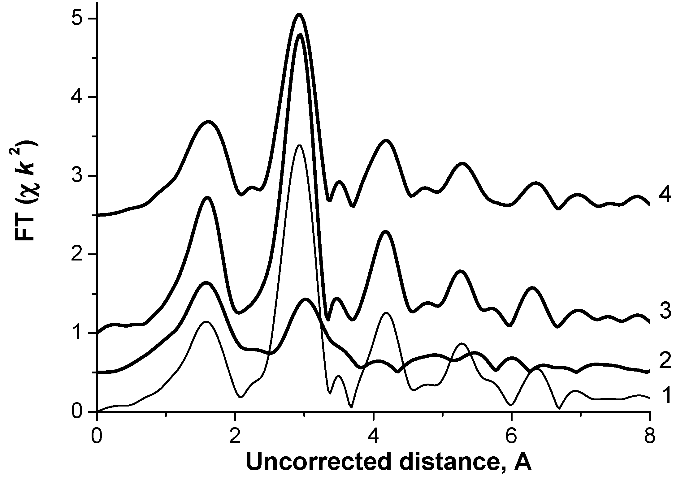
| Sample | Path | R, Å | CN | σ × 10−3, Å−2 | Δ E, eV |
|---|---|---|---|---|---|
| Initial | Zn–O | 2.04 ± 0.01 | 3.3 ± 0.2 | 8.2 ± 1 | 11.6 ± 0.9 |
| Zn–Zn | 3.26 ± 0.01 | 4.7 ± 0.6 | 9.8 ± 1 | 23.1 ± 1.3 | |
| Treated | Zn–O | 2.00 ± 0.02 | 3.2 ± 0.6 | 5.2 ± 2.3 | 13.9 ± 3.4 |
| Zn–Zn | 3.22 ± 0.05 | 11.3 ± 1.1 | 6.1 ± 0.7 | 7.5 ± 0.8 | |
| After catalysis | Zn–O | 2.02 ± 0.02 | 3.4 ± 0.7 | 7.6 ± 2.0 | 15.0 ± 3.2 |
| Zn–Zn | 3.22 ± 0.01 | 10.2 ± 1.1 | 7.8 ± 0.8 | 6.8 ± 1.0 |
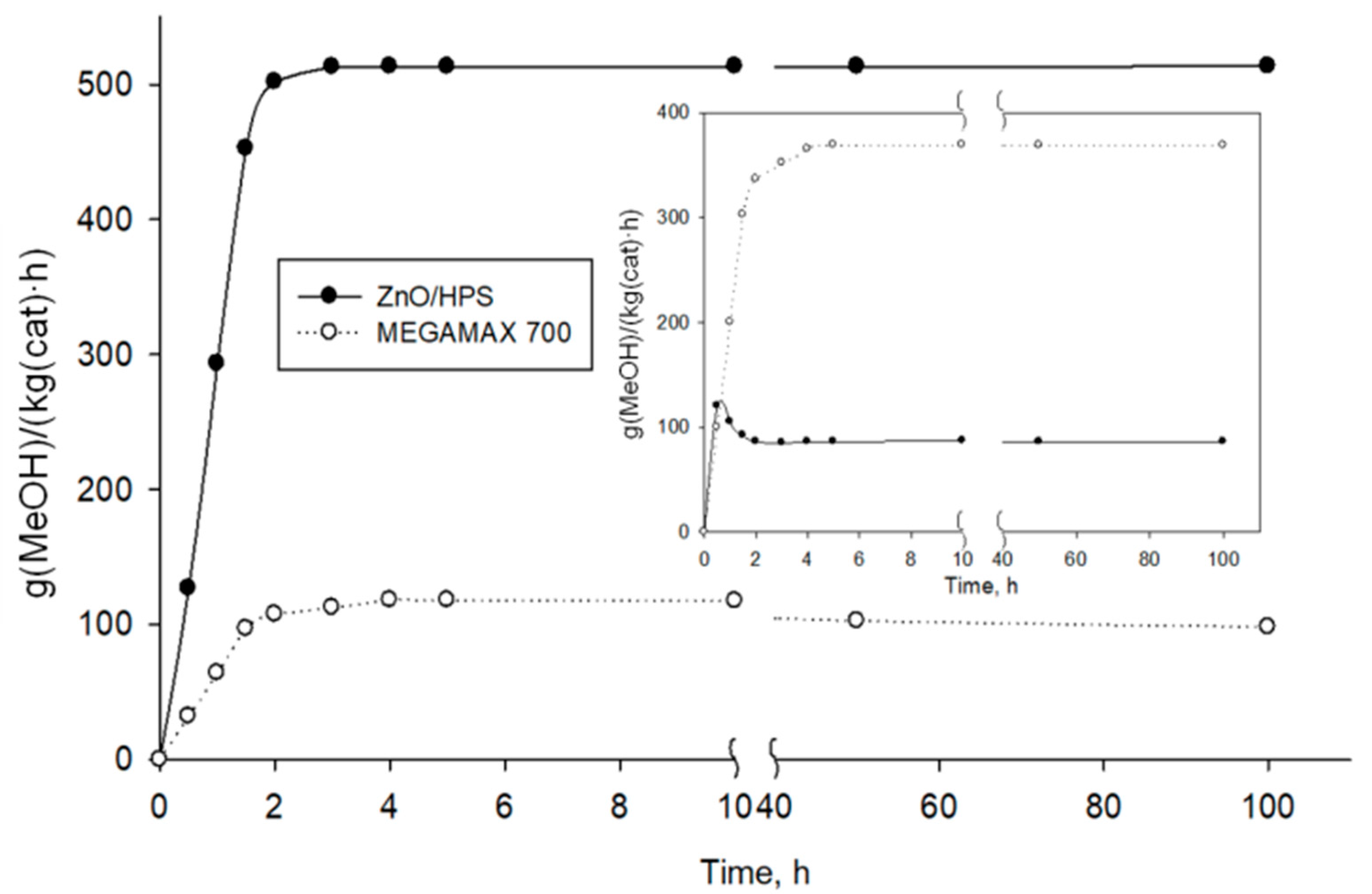
| Sample | CO Conversion, mol.% | MeOH Selectivity, mol.% | Selectivity after 100 h, mol.% |
|---|---|---|---|
| ZnO-HPS | 67.2 | 99.8 | 99.8 |
| MEGAMAX® 700 | 30.4 | 97.5 | 95.3 |
| Cu/ZnO/Al2O3 [24] | 44.5 | 99.4 | 97.8 |
Disclaimer/Publisher’s Note: The statements, opinions and data contained in all publications are solely those of the individual author(s) and contributor(s) and not of MDPI and/or the editor(s). MDPI and/or the editor(s) disclaim responsibility for any injury to people or property resulting from any ideas, methods, instructions or products referred to in the content. |
© 2023 by the authors. Licensee MDPI, Basel, Switzerland. This article is an open access article distributed under the terms and conditions of the Creative Commons Attribution (CC BY) license (https://creativecommons.org/licenses/by/4.0/).
Share and Cite
Doluda, V.Y.; Tkachenko, O.P.; Stepacheva, A.A.; Sidorov, A.I.; Bykov, A.V.; Sulman, M.G.; Kosivtsov, Y.Y. ZnO Particles Stabilized in Polymeric Matrix for Liquid-Phase Methanol Synthesis. Catalysts 2023, 13, 116. https://doi.org/10.3390/catal13010116
Doluda VY, Tkachenko OP, Stepacheva AA, Sidorov AI, Bykov AV, Sulman MG, Kosivtsov YY. ZnO Particles Stabilized in Polymeric Matrix for Liquid-Phase Methanol Synthesis. Catalysts. 2023; 13(1):116. https://doi.org/10.3390/catal13010116
Chicago/Turabian StyleDoluda, Valentin Yu., Olga P. Tkachenko, Antonina A. Stepacheva, Alexander I. Sidorov, Alexey V. Bykov, Mikhail G. Sulman, and Yury Yu. Kosivtsov. 2023. "ZnO Particles Stabilized in Polymeric Matrix for Liquid-Phase Methanol Synthesis" Catalysts 13, no. 1: 116. https://doi.org/10.3390/catal13010116