
Oxygenated Hydrocarbons from Catalytic Hydrogenation of Carbon Dioxide


Abstract
:1. Introduction
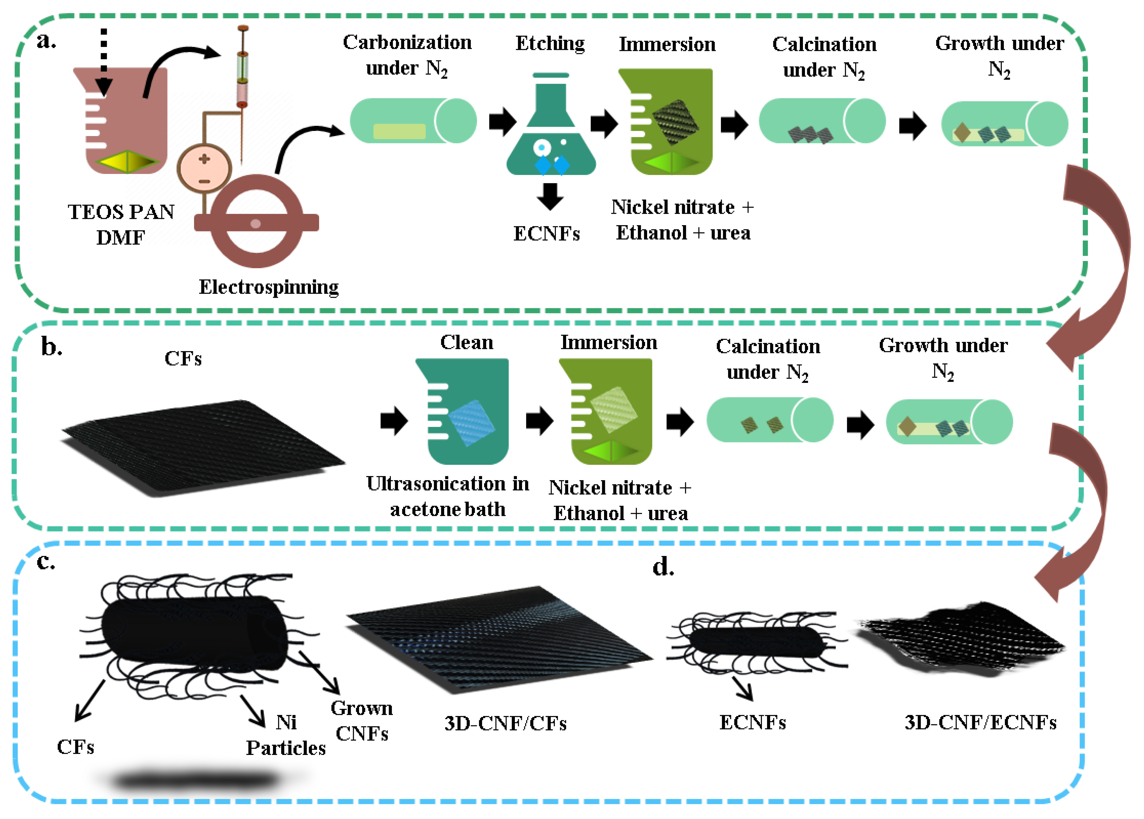
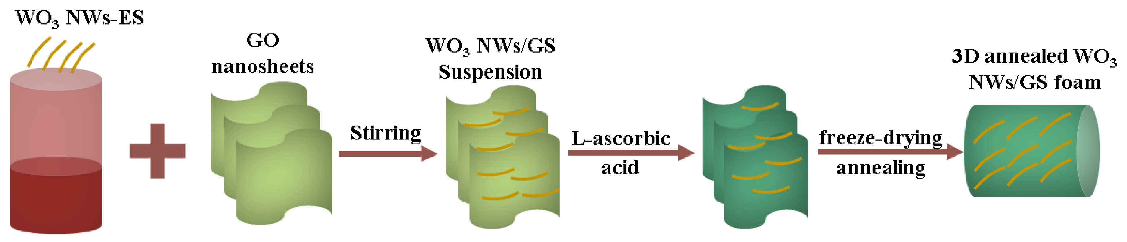
2. Synthesis of 3D-Structure Materials
3. Graphene Production Methods
3.1. Chemical Vapor Deposition (CVD)-Based Methods
3.2. Solution-Based Methods
3.3. Three-Dimensional (3D) Printing
3.4. Hydrothermal Method
3.5. In Situ Chemical Reduction
3.6. Pyrolysis of Organic Precursors
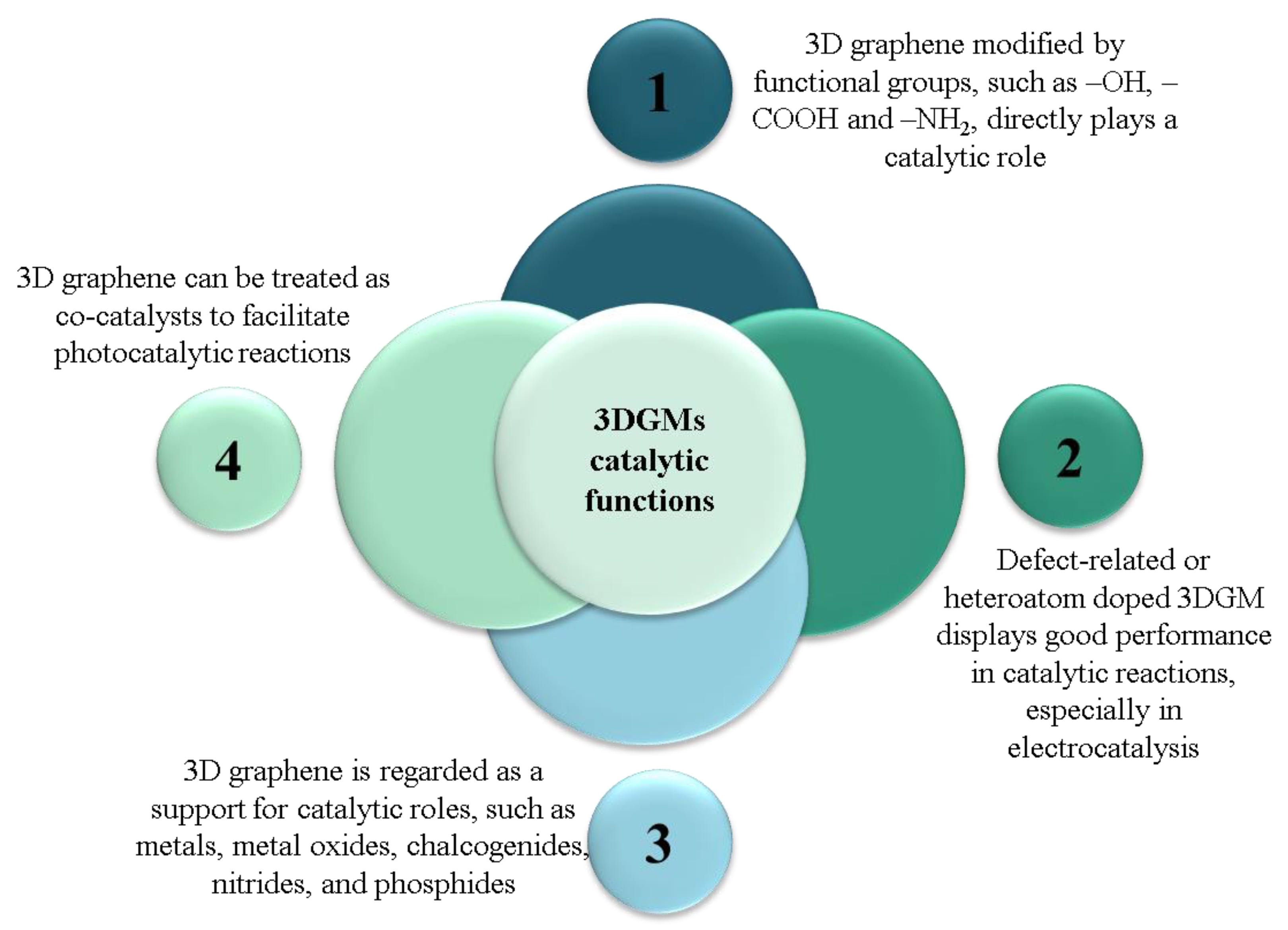
4. Uses of Graphene as a Catalyst
5. CNT Production Methods
5.1. Arc Discharge
5.2. Laser Ablation
5.3. Chemical Vapor Deposition (CVD)
5.4. Plasma Torch
6. Uses of CNT as a Catalyst
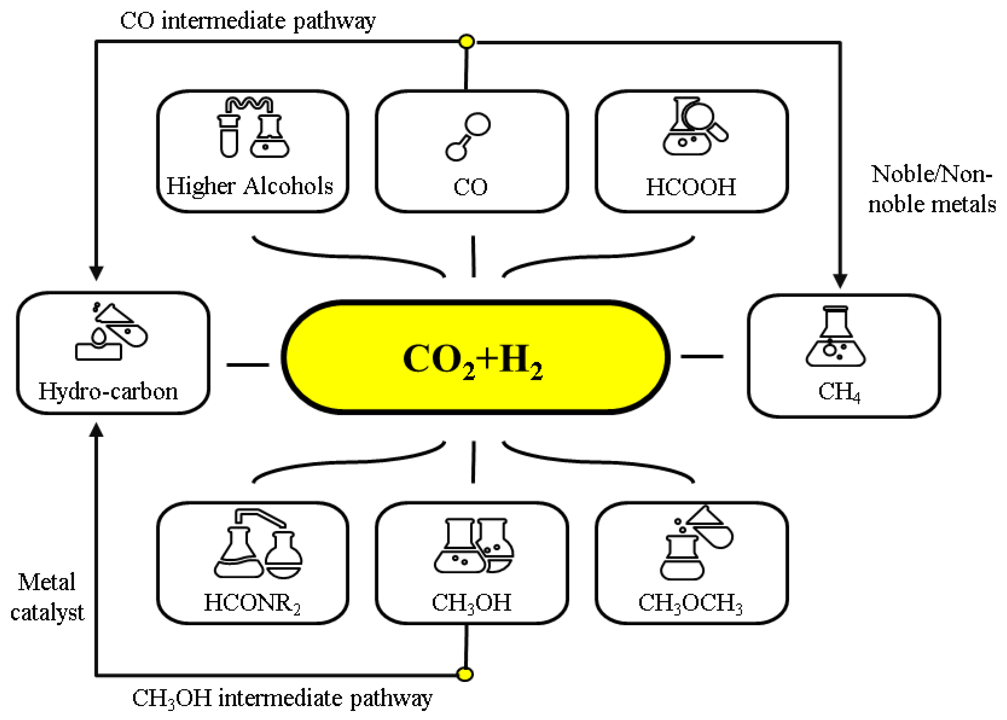
7. CO2 Hydrogenation into Hydrocarbons and Oxygenated Hydrocarbons
8. Mechanism of Conversion
Examples of Conversion Mechanisms
9. Theoretical Studies of CO2 Conversion
10. Preparation and Approximate Cost of CNTs
11. CNTs as Catalysts
12. Conclusions
Author Contributions
Funding
Acknowledgments
Conflicts of Interest
References
- Ma, R.; Xu, B.; Zhang, X. Catalytic partial oxidation (CPOX) of natural gas and renewable hydrocarbons/oxygenated hydrocarbons—A review. Catal. Today 2019, 338, 18–30. [Google Scholar] [CrossRef]
- Hasan, S.Z.; Ahmad, K.N.; Isahak, W.N.R.W.; Pudukudy, M.; Masdar, M.S.; Jahim, J.M. Synthesis, Characterisation and Catalytic Activity of NiO supported Al2O3 for CO2 Hydrogenation to Carboxylic Acids: Influence of Catalyst Structure. IOP Conf. Ser. Earth Environ. Sci. 2019, 268, 012079. [Google Scholar] [CrossRef]
- Palmeri, N.; Chiodo, V.; Freni, S.; Frusteri, F.; Bart, J.; Cavallaro, S. Hydrogen from oxygenated solvents by steam reforming on Ni/Al2O3 catalyst. Int. J. Hydrogen Energy 2008, 33, 6627–6634. [Google Scholar] [CrossRef]
- Kahn, B. Earth’s CO2 Passes the 400 PPM Threshold—Maybe Permanently. Sci. Am. 2016. Available online: https://www.scientificamerican.com/article/earth-s-co2-passes-the-400-ppm-threshold-maybe-permanently/ (accessed on 1 November 2022).
- Capros, P.; Tasios, N.; De Vita, A.; Mantzos, L.; Paroussos, L. Model-based analysis of decarbonising the EU economy in the time horizon to 2050. Energy Strat. Rev. 2012, 1, 76–84. [Google Scholar] [CrossRef]
- European Commission. A Roadmap for Moving to a Competitive Low Carbon Economy in 2050. COM(2011) 112 Final; European Commission: Brussels, Belgium, 2011; Volume 34, pp. 1–34. [Google Scholar]
- Dimitriou, I.; García-Gutiérrez, P.; Elder, R.H.; Cuéllar-Franca, R.M.; Azapagic, A.; Allen, R.W.K. Carbon dioxide utilisation for production of transport fuels: Process and economic analysis. Energy Environ. Sci. 2015, 8, 1775–1789. [Google Scholar] [CrossRef] [Green Version]
- Ma, X.; Wang, X.; Song, C. “Molecular Basket” Sorbents for Separation of CO2 and H2S from Various Gas Streams. J. Am. Chem. Soc. 2009, 131, 5777–5783. [Google Scholar] [CrossRef]
- Du, G.; Lim, S.; Yang, Y.; Wang, C.; Pfefferle, L.; Haller, G.L. Methanation of carbon dioxide on Ni-incorporated MCM-41 catalysts: The influence of catalyst pretreatment and study of steady-state reaction. J. Catal. 2007, 249, 370–379. [Google Scholar] [CrossRef]
- Duyar, M.S.; Treviño, M.A.A.; Farrauto, R.J. Dual function materials for CO2 capture and conversion using renewable H2. Appl. Catal. B Environ. 2015, 168–169, 370–376. [Google Scholar] [CrossRef]
- Lee, C.-Y.; Zhao, Y.; Wang, C.; Mitchell, D.R.G.; Wallace, G.G. Rapid formation of self-organised Ag nanosheets with high efficiency and selectivity in CO2 electroreduction to CO. Sustain. Energy Fuels 2017, 1, 1023–1027. [Google Scholar] [CrossRef]
- Li, K.; Peng, B.; Peng, T. Recent Advances in Heterogeneous Photocatalytic CO2 Conversion to Solar Fuels. ACS Catal. 2016, 6, 7485–7527. [Google Scholar] [CrossRef]
- Welch, A.J.; DuChene, J.S.; Tagliabue, G.; Davoyan, A.R.; Cheng, W.-H.; Atwater, H.A. Nanoporous Gold as a Highly Selective and Active Carbon Dioxide Reduction Catalyst. ACS Appl. Energy Mater. 2019, 2, 164–170. [Google Scholar] [CrossRef] [Green Version]
- Xie, H.; Wang, T.; Liang, J.; Li, Q.; Sun, S. Cu-based nanocatalysts for electrochemical reduction of CO2. Nano Today 2018, 21, 41–54. [Google Scholar] [CrossRef]
- Huang, H.; Jia, H.; Liu, Z.; Gao, P.; Zhao, J.; Luo, Z.; Yang, J.; Zeng, J. Understanding of Strain Effects in the Electrochemical Reduction of CO2: Using Pd Nanostructures as an Ideal Platform. Angew. Chem. Int. Ed. 2017, 56, 3594–3598. [Google Scholar] [CrossRef]
- Ma, M.; Trześniewski, B.J.; Xie, J.; Smith, W.A. Selective and Efficient Reduction of Carbon Dioxide to Carbon Monoxide on Oxide-Derived Nanostructured Silver Electrocatalysts. Angew. Chem. Int. Ed. 2016, 55, 9748–9752. [Google Scholar] [CrossRef] [Green Version]
- Su, P.; Xu, W.; Qiu, Y.; Zhang, T.; Li, X.; Zhang, H. Ultrathin Bismuth Nanosheets as a Highly Efficient CO2 Reduction Electrocatalyst. Chemsuschem 2018, 11, 848–853. [Google Scholar] [CrossRef]
- Li, Q.; Fu, J.; Zhu, W.; Chen, Z.; Shen, B.; Wu, L.; Xi, Z.; Wang, T.; Lu, G.; Zhu, J.-J.; et al. Tuning Sn-Catalysis for Electrochemical Reduction of CO2 to CO via the Core/Shell Cu/SnO2 Structure. J. Am. Chem. Soc. 2017, 139, 4290–4293. [Google Scholar] [CrossRef]
- Hu, X.-M.; Rønne, M.H.; Pedersen, S.U.; Skrydstrup, T.; Daasbjerg, K. Enhanced Catalytic Activity of Cobalt Porphyrin in CO2 Electroreduction upon Immobilization on Carbon Materials. Angew. Chem. Int. Ed. 2017, 56, 6468–6472. [Google Scholar] [CrossRef]
- Chen, Q.; Tsiakaras, P.; Shen, P. Electrochemical Reduction of Carbon Dioxide: Recent Advances on Au-Based Nanocatalysts. Catalysts 2022, 12, 1348. [Google Scholar] [CrossRef]
- Brouzgou, A.; Song, S.; Liang, Z.-X.; Tsiakaras, P. Non-Precious Electrocatalysts for Oxygen Reduction Reaction in Alkaline Media: Latest Achievements on Novel Carbon Materials. Catalysts 2016, 6, 159. [Google Scholar] [CrossRef]
- Alaba, P.A.; Abbas, A.; Daud, W.M.W. Insight into catalytic reduction of CO2: Catalysis and reactor design. J. Clean. Prod. 2017, 140, 1298–1312. [Google Scholar] [CrossRef]
- Centi, G.; Perathoner, S. CO2-based energy vectors for the storage of solar energy. Greenh. Gases Sci. Technol. 2011, 1, 21–35. [Google Scholar] [CrossRef]
- Porosoff, M.D.; Yan, B.; Chen, J.G. Catalytic reduction of CO2 by H2 for synthesis of CO, methanol and hydrocarbons: Challenges and opportunities. Energy Environ. Sci. 2016, 9, 62–73. [Google Scholar] [CrossRef]
- Gao, P.; Li, S.; Bu, X.; Dang, S.; Liu, Z.; Wang, H.; Zhong, L.; Qiu, M.; Yang, C.; Cai, J.; et al. Direct conversion of CO2 into liquid fuels with high selectivity over a bifunctional catalyst. Nat. Chem. 2017, 9, 1019–1024. [Google Scholar] [CrossRef] [PubMed]
- Song, H.; Zhang, N.; Zhong, C.; Liu, Z.; Xiao, M.; Gai, H. Hydrogenation of CO2 into formic acid using a palladium catalyst on chitin. New J. Chem. 2017, 41, 9170–9177. [Google Scholar] [CrossRef]
- Visconti, C.G.; Martinelli, M.; Falbo, L.; Infantes-Molina, A.; Lietti, L.; Forzatti, P.; Iaquaniello, G.; Palo, E.; Picutti, B.; Brignoli, F. CO2 hydrogenation to lower olefins on a high surface area K-promoted bulk Fe-catalyst. Appl. Catal. B Environ. 2017, 200, 530–542. [Google Scholar] [CrossRef]
- Larmier, K.; Liao, W.-C.; Tada, S.; Lam, E.; Verel, R.; Bansode, A.; Urakawa, A.; Comas-Vives, A.; Copéret, C. CO2-to-Methanol Hydrogenation on Zirconia-Supported Copper Nanoparticles: Reaction Intermediates and the Role of the Metal-Support Interface. Angew. Chem. Int. Ed. 2017, 56, 2318–2323. [Google Scholar] [CrossRef]
- Bai, S.; Shao, Q.; Wang, P.; Dai, Q.; Wang, X.; Huang, X. Highly Active and Selective Hydrogenation of CO2 to Ethanol by Ordered Pd–Cu Nanoparticles. J. Am. Chem. Soc. 2017, 139, 6827–6830. [Google Scholar] [CrossRef]
- Sorcar, S.; Hwang, Y.; Lee, J.; Kim, H.; Grimes, K.M.; Grimes, C.A.; Jung, J.-W.; Cho, C.-H.; Majima, T.; Hoffmann, M.R.; et al. CO2, water, and sunlight to hydrocarbon fuels: A sustained sunlight to fuel (Joule-to-Joule) photoconversion efficiency of 1%. Energy Environ. Sci. 2019, 12, 2685–2696. [Google Scholar] [CrossRef] [Green Version]
- Tan, Z.; Ni, K.; Chen, G.; Zeng, W.; Tao, Z.; Ikram, M.; Zhang, Q.; Wang, H.; Sun, L.; Zhu, X.; et al. Incorporating Pyrrolic and Pyridinic Nitrogen into a Porous Carbon made from C60Molecules to Obtain Superior Energy Storage. Adv. Mater. 2017, 29, 160341. [Google Scholar] [CrossRef]
- Chen, J.; Xue, C.; Ramasubramaniam, R.; Liu, H. A new method for the preparation of stable carbon nanotube organogels. Carbon 2006, 44, 2142–2146. [Google Scholar] [CrossRef]
- Navrotskaya, A.G.; Aleksandrova, D.D.; Krivoshapkina, E.F.; Sillanpää, M.; Krivoshapkin, P.V. Hybrid Materials Based on Carbon Nanotubes and Nanofibers for Environmental Applications. Front. Chem. 2020, 8, 546. [Google Scholar] [CrossRef]
- Worsley, M.A.; Shin, S.J.; Merrill, M.D.; Lenhardt, J.; Nelson, A.J.; Woo, L.Y.; Gash, A.E.; Baumann, T.F.; Orme, C.A. Ultralow Density, Monolithic WS2, MoS2, and MoS2/Graphene Aerogels. ACS Nano 2015, 9, 4698–4705. [Google Scholar] [CrossRef] [Green Version]
- Mamba, G.; Mishra, A.K. Graphitic carbon nitride (g-C3N4) nanocomposites: A new and exciting generation of visible light driven photocatalysts for environmental pollution remediation. Appl. Catal. B Environ. 2016, 198, 347–377. [Google Scholar] [CrossRef]
- Kovtyukhova, N.I.; Mallouk, T.E.; Pan, A.L.; Dickey, E.C. Individual Single-Walled Nanotubes and Hydrogels Made by Oxidative Exfoliation of Carbon Nanotube Ropes. J. Am. Chem. Soc. 2003, 125, 9761–9769. [Google Scholar] [CrossRef]
- Sun, Y.; Wu, Q.; Xu, Y.; Bai, H.; Li, C.; Shi, G. Highly conductive and flexible mesoporous graphitic films prepared by graphitizing the composites of graphene oxide and nanodiamond. J. Mater. Chem. 2011, 21, 7154–7160. [Google Scholar] [CrossRef]
- Bryning, M.B.; Milkie, D.E.; Islam, M.F.; Hough, L.A.; Kikkawa, J.M.; Yodh, A.G. Carbon Nanotube Aerogels. Adv. Mater. 2007, 19, 661–664. [Google Scholar] [CrossRef]
- Gui, X.; Wei, J.; Wang, K.; Cao, A.; Zhu, H.; Jia, Y.; Shu, Q.; Wu, D. Carbon Nanotube Sponges. Adv. Mater. 2010, 22, 617–621. [Google Scholar] [CrossRef]
- Zhang, L.L.; Xiong, Z.; Zhao, X.S. Pillaring Chemically Exfoliated Graphene Oxide with Carbon Nanotubes for Photocatalytic Degradation of Dyes under Visible Light Irradiation. ACS Nano 2010, 4, 7030–7036. [Google Scholar] [CrossRef]
- Zhu, Y.; Li, L.; Zhang, C.; Casillas, G.; Sun, Z.; Yan, Z.; Ruan, G.; Peng, Z.; Raji, A.-R.; Kittrell, C.; et al. A seamless three-dimensional carbon nanotube graphene hybrid material. Nat. Commun. 2012, 3, 1225. [Google Scholar] [CrossRef] [Green Version]
- Tripathi, M.; Valentini, L.; Rong, Y.; Bon, S.B.; Pantano, M.F.; Speranza, G.; Guarino, R.; Novel, D.; Iacob, E.; Liu, W.; et al. Free-Standing Graphene Oxide and Carbon Nanotube Hybrid Papers with Enhanced Electrical and Mechanical Performance and Their Synergy in Polymer Laminates. Int. J. Mol. Sci. 2020, 21, 8585. [Google Scholar] [CrossRef] [PubMed]
- Liu, J.; Zhang, L.; Bin Wu, H.; Lin, J.; Shen, Z.; Lou, X.W. High-performance flexible asymmetric supercapacitors based on a new graphene foam/carbon nanotube hybrid film. Energy Environ. Sci. 2014, 7, 3709–3719. [Google Scholar] [CrossRef]
- Jin, S.; Xin, S.; Wang, L.; Du, Z.; Cao, L.; Chen, J.; Kong, X.; Gong, M.; Lu, J.; Zhu, Y.; et al. Covalently Connected Carbon Nanostructures for Current Collectors in Both the Cathode and Anode of Li-S Batteries. Adv. Mater. 2016, 28, 9094–9102. [Google Scholar] [CrossRef]
- Peng, Q.; Li, Y.; He, X.; Gui, X.; Shang, Y.; Wang, C.; Wang, C.; Zhao, W.; Du, S.; Shi, E.; et al. Graphene Nanoribbon Aerogels Unzipped from Carbon Nanotube Sponges. Adv. Mater. 2014, 26, 3241–3247. [Google Scholar] [CrossRef]
- Chen, L.; Du, R.; Zhu, J.; Mao, Y.; Xue, C.; Zhang, N.; Hou, Y.; Zhang, J.; Yi, T. Three-Dimensional Nitrogen-Doped Graphene Nanoribbons Aerogel as a Highly Efficient Catalyst for the Oxygen Reduction Reaction. Small 2015, 11, 1423–1429. [Google Scholar] [CrossRef] [PubMed]
- Chen, L.-F.; Zhang, X.-D.; Liang, H.-W.; Kong, M.; Guan, Q.-F.; Chen, P.; Wu, Z.-Y.; Yu, S.-H. Synthesis of Nitrogen-Doped Porous Carbon Nanofibers as an Efficient Electrode Material for Supercapacitors. ACS Nano 2012, 6, 7092–7102. [Google Scholar] [CrossRef] [PubMed]
- Chen, L.-F.; Huang, Z.-H.; Liang, H.-W.; Gao, H.-L.; Yu, S.-H. Three-Dimensional Heteroatom-Doped Carbon Nanofiber Networks Derived from Bacterial Cellulose for Supercapacitors. Adv. Funct. Mater. 2014, 24, 5104–5111. [Google Scholar] [CrossRef]
- Yan, X.; You, H.; Liu, W.; Wang, X.; Wu, D. Free-Standing and Heteroatoms-Doped Carbon Nanofiber Networks as a Binder-Free Flexible Electrode for High-Performance Supercapacitors. Nanomaterials 2019, 9, 1189. [Google Scholar] [CrossRef] [Green Version]
- He, Z.; Yang, Y.; Liu, J.-W.; Yu, S.-H. Emerging tellurium nanostructures: Controllable synthesis and their applications. Chem. Soc. Rev. 2017, 46, 2732–2753. [Google Scholar] [CrossRef]
- Luo, W.; Chen, X.; Wei, Z.; Liu, D.; Yao, W.; Zhu, Y. Three-dimensional network structure assembled by g-C3N4 nanorods for improving visible-light photocatalytic performance. Appl. Catal. B Environ. 2019, 255, 117761. [Google Scholar] [CrossRef]
- Ou, H.; Yang, P.; Lin, L.; Anpo, M.; Wang, X. Carbon Nitride Aerogels for the Photoredox Conversion of Water. Angew. Chem. Int. Ed. 2017, 56, 10905–10910. [Google Scholar] [CrossRef] [PubMed]
- Abu-Zied, B.M.; Alamry, K.A. Green synthesis of 3D hierarchical nanostructured Co3O4/carbon catalysts for the application in sodium borohydride hydrolysis. J. Alloy. Compd. 2019, 798, 820–831. [Google Scholar] [CrossRef]
- Liu, J.J.; Xu, Y.X. Three-dimensional Graphene-based Composites and Two-dimensional Polymers: Synthesis and Application in Energy Storage and Conversion. Acta Polym. Sin. 2019, 50, 219–232. [Google Scholar]
- Alali, K.T.; Yu, J.; Moharram, D.; Liu, Q.; Chen, R.; Zhu, J.; Li, R.; Liu, P.; Liu, J.; Wang, J. In situ construction of 3-dimensional hierarchical carbon nanostructure; investigation of the synthesis parameters and hydrogen evolution reaction performance. Carbon 2021, 178, 48–57. [Google Scholar] [CrossRef]
- Ferrari, A.C.; Bonaccorso, F.; Fal’Ko, V.; Novoselov, K.S.; Roche, S.; Bøggild, P.; Borini, S.; Koppens, F.H.L.; Palermo, V.; Pugno, N.; et al. Science and technology roadmap for graphene, related two-dimensional crystals, and hybrid systems. Nanoscale 2015, 7, 4598–4810. [Google Scholar] [CrossRef] [Green Version]
- Arjmandi-Tash, H.; Lebedev, N.; van Deursen, P.M.; Aarts, J.; Schneider, G.F. Hybrid cold and hot-wall reaction chamber for the rapid synthesis of uniform graphene. Carbon 2017, 118, 438–442. [Google Scholar] [CrossRef]
- Alnuaimi, A.; Almansouri, I.; Saadat, I.; Nayfeh, A. Toward fast growth of large area high quality graphene using a cold-wall CVD reactor. RSC Adv. 2017, 7, 51951–51957. [Google Scholar] [CrossRef] [Green Version]
- Al-Hagri, A.; Li, R.; Rajput, N.S.; Lu, C.; Cong, S.; Sloyan, K.; Almahri, M.A.; Tamalampudi, S.R.; Chiesa, M.; Al Ghaferi, A. Direct growth of single-layer terminated vertical graphene array on germanium by plasma enhanced chemical vapor deposition. Carbon 2019, 155, 320–325. [Google Scholar] [CrossRef]
- Chen, Y.-C.; Lin, W.-H.; Tseng, W.-S.; Chen, C.-C.; Rossman, G.; Chen, C.-D.; Wu, Y.-S.; Yeh, N.-C. Direct growth of mm-size twisted bilayer graphene by plasma-enhanced chemical vapor deposition. Carbon 2020, 156, 212–224. [Google Scholar] [CrossRef]
- Sohn, K.; Na, Y.J.; Chang, H.; Roh, K.-M.; Jang, H.D.; Huang, J. Oil absorbing graphene capsules by capillary molding. Chem. Commun. 2012, 48, 5968–5970. [Google Scholar] [CrossRef]
- Yan, J.; Ding, Y.; Hu, C.; Cheng, H.; Chen, N.; Feng, Z.; Zhang, Z.; Qu, L. Preparation of multifunctional microchannel-network graphene foams. J. Mater. Chem. A 2014, 2, 16786–16792. [Google Scholar] [CrossRef]
- Shunxin, J. A Simple Solution-Based Method to Prepare Honeycomb-Like Li2S/Graphene Composite for Lithium-Sulfur Batteries. Int. J. Electrochem. Sci. 2018, 13, 3407–3419. [Google Scholar] [CrossRef]
- Moura, D.; Pereira, R.F.; Gonçalves, I.C. Recent advances on bioprinting of hydrogels containing carbon materials. Mater. Today Chem. 2022, 23, 100617. [Google Scholar] [CrossRef]
- Sha, J.; Li, Y.; Salvatierra, R.V.; Wang, T.; Dong, P.; Ji, Y.; Lee, S.-K.; Zhang, C.; Zhang, J.; Smith, R.H.; et al. Three-Dimensional Printed Graphene Foams. ACS Nano 2017, 11, 6860–6867. [Google Scholar] [CrossRef] [PubMed] [Green Version]
- Tang, X.; Zhou, H.; Cai, Z.; Cheng, D.; He, P.; Xie, P.; Zhang, D.; Fan, T. Generalized 3D Printing of Graphene-Based Mixed-Dimensional Hybrid Aerogels. ACS Nano 2018, 12, 3502–3511. [Google Scholar] [CrossRef]
- Yu, Z.-Y.; Chen, L.-F.; Song, L.-T.; Zhu, Y.-W.; Ji, H.-X.; Yu, S.-H. Free-standing boron and oxygen co-doped carbon nanofiber films for large volumetric capacitance and high rate capability supercapacitors. Nano Energy 2015, 15, 235–243. [Google Scholar] [CrossRef]
- Bai, X.-L.; Gao, Y.-L.; Gao, Z.-Y.; Ma, J.-Y.; Tong, X.-L.; Sun, H.-B.; Wang, J.A. Supercapacitor performance of 3D-graphene/MnO2 foam synthesized via the combination of chemical vapor deposition with hydrothermal method. Appl. Phys. Lett. 2020, 117, 183901. [Google Scholar] [CrossRef]
- Li, J.; Yang, S.; Jiao, P.; Peng, Q.; Yin, W.; Yuan, Y.; Lu, H.; He, X.; Li, Y. Three-dimensional macroassembly of hybrid C@CoFe nanoparticles/reduced graphene oxide nanosheets towards multifunctional foam. Carbon 2020, 157, 427–436. [Google Scholar] [CrossRef]
- Liu, W.; Cai, J.; Li, Z. Self-Assembly of Semiconductor Nanoparticles/Reduced Graphene Oxide (RGO) Composite Aerogels for Enhanced Photocatalytic Performance and Facile Recycling in Aqueous Photocatalysis. ACS Sustain. Chem. Eng. 2015, 3, 277–282. [Google Scholar] [CrossRef]
- Zhang, M.; Song, Z.; Liu, H.; Wang, A.; Shao, S. MoO2 coated few layers of MoS2 and FeS2 nanoflower decorated S-doped graphene interoverlapped network for high-energy asymmetric supercapacitor. J. Colloid Interface Sci. 2021, 584, 418–428. [Google Scholar] [CrossRef] [PubMed]
- Park, S.; An, J.; Potts, J.R.; Velamakanni, A.; Murali, S.; Ruoff, R.S. Hydrazine-reduction of graphite- and graphene oxide. Carbon 2011, 49, 3019–3023. [Google Scholar] [CrossRef]
- Yan, L.; Zhou, M.; Pang, X.; Gao, K. One-Step in Situ Synthesis of Reduced Graphene Oxide/Zn–Al Layered Double Hydroxide Film for Enhanced Corrosion Protection of Magnesium Alloys. Langmuir 2019, 35, 6312–6320. [Google Scholar] [CrossRef]
- Shandilya, P.; Mittal, D.; Sudhaik, A.; Soni, M.; Raizada, P.; Saini, A.; Singh, P. GdVO4 modified fluorine doped graphene nanosheets as dispersed photocatalyst for mitigation of phenolic compounds in aqueous environment and bacterial disinfection. Sep. Purif. Technol. 2019, 210, 804–816. [Google Scholar] [CrossRef]
- Santos, F.C.U.; Paim, L.L.; da Silva, J.L.; Stradiotto, N.R. Electrochemical determination of total reducing sugars from bioethanol production using glassy carbon electrode modified with graphene oxide containing copper nanoparticles. Fuel 2016, 163, 112–121. [Google Scholar] [CrossRef] [Green Version]
- Chen, W.; Li, S.; Chen, C.; Yan, L. Self-Assembly and Embedding of Nanoparticles by In Situ Reduced Graphene for Preparation of a 3D Graphene/Nanoparticle Aerogel. Adv. Mater. 2011, 23, 5679–5683. [Google Scholar] [CrossRef] [PubMed]
- Kabtamu, D.M.; Chang, Y.-C.; Lin, G.-Y.; Bayeh, A.W.; Chen, J.-Y.; Wondimu, T.H.; Wang, C.-H. Three-dimensional annealed WO3 nanowire/graphene foam as an electrocatalytic material for all vanadium redox flow batteries. Sustain. Energy Fuels 2017, 1, 2091–2100. [Google Scholar] [CrossRef]
- Cai, L.; Lin, Z.; Wang, M.; Pan, F.; Chen, J.; Wang, Y.; Shen, X.; Chai, Y. Improved interfacial H2O supply by surface hydroxyl groups for enhanced alkaline hydrogen evolution. J. Mater. Chem. A 2017, 5, 24091–24097. [Google Scholar] [CrossRef]
- Worsley, M.A.; Pauzauskie, P.J.; Olson, T.Y.; Biener, J.; Satcher, J.J.H.; Baumann, T.F. Synthesis of Graphene Aerogel with High Electrical Conductivity. J. Am. Chem. Soc. 2010, 132, 14067–14069. [Google Scholar] [CrossRef]
- Zhang, L.; Li, H.; Lai, X.; Wu, W.; Zeng, X. Hindered phenol functionalized graphene oxide for natural rubber. Mater. Lett. 2018, 210, 239–242. [Google Scholar] [CrossRef]
- Bustos-Ramírez, K.; Martínez-Hernández, A.L.; Martínez-Barrera, G.; De Icaza, M.; Castaño, V.M.; Velasco-Santos, C. Covalently Bonded Chitosan on Graphene Oxide via Redox Reaction. Materials 2013, 6, 911–926. [Google Scholar] [CrossRef] [Green Version]
- To, J.W.F.; Chen, Z.; Yao, H.; He, J.; Kim, K.; Chou, H.-H.; Pan, L.; Wilcox, J.; Cui, Y.; Bao, Z. Ultrahigh Surface Area Three-Dimensional Porous Graphitic Carbon from Conjugated Polymeric Molecular Framework. ACS Central Sci. 2015, 1, 68–76. [Google Scholar] [CrossRef] [PubMed] [Green Version]
- Fang, B.; Chang, D.; Xu, Z.; Gao, C. A Review on Graphene Fibers: Expectations, Advances, and Prospects. Adv. Mater. 2020, 32, e1902664. [Google Scholar] [CrossRef] [PubMed]
- Hummers, W.S., Jr.; Offeman, R.E. Preparation of Graphitic Oxide. J. Am. Chem. Soc. 1958, 80, 1339. [Google Scholar] [CrossRef]
- Lawal, A.T. Graphene-based nano composites and their applications. A review. Biosens. Bioelectron. 2019, 141, 111384. [Google Scholar] [CrossRef] [PubMed]
- Zhao, W.; Liu, H.; Meng, N.; Jian, M.; Wang, H.; Zhang, X. Graphene oxide incorporated thin film nanocomposite membrane at low concentration monomers. J. Membr. Sci. 2018, 565, 380–389. [Google Scholar] [CrossRef]
- Akyüz, D.; Koca, A. Photocatalytic hydrogen production with reduced graphene oxide (RGO)-CdZnS nano-composites synthesized by solvothermal decomposition of dimethyl sulfoxide as the sulfur source. J. Photochem. Photobiol. A Chem. 2018, 364, 625–634. [Google Scholar] [CrossRef]
- Kumar, N.; Rodriguez, J.R.; Pol, V.G.; Sen, A. Facile synthesis of 2D graphene oxide sheet enveloping ultrafine 1D LiMn2O4 as interconnected framework to enhance cathodic property for Li-ion battery. Appl. Surf. Sci. 2019, 463, 132–140. [Google Scholar] [CrossRef] [Green Version]
- Aghazadeh, M. One-step electrophoretic/electrochemical synthesis of reduced graphene oxide/manganese oxide (RGO-Mn3O4) nanocomposite and study of its capacitive performance. Anal. Bioanal. Electrochem. 2018, 10, 961–973. [Google Scholar]
- Jasmi, F.; Azeman, N.H.; Bakar, A.A.A.; Zan, M.S.D.; Badri, K.H.; Su’Ait, M.S. Ionic Conductive Polyurethane-Graphene Nanocomposite for Performance Enhancement of Optical Fiber Bragg Grating Temperature Sensor. IEEE Access 2018, 6, 47355–47363. [Google Scholar] [CrossRef]
- Novoselov, K.S.; Geim, A.K.; Morozov, S.V.; Jiang, D.; Zhang, Y.; Dubonos, S.V.; Grigoreieva, I.V.; Firsov, A.A. Electric Field Effect in Atomically Thin Carbon Films Supplementary. Science 2004, 5, 105–110. [Google Scholar] [CrossRef] [Green Version]
- Qiu, B.; Li, Q.; Shen, B.; Xing, M.; Zhang, J. Stöber-like method to synthesize ultradispersed Fe3O4 nanoparticles on graphene with excellent Photo-Fenton reaction and high-performance lithium storage. Appl. Catal. B Environ. 2016, 183, 216–223. [Google Scholar] [CrossRef]
- Wang, Y.; Zheng, Y.; Xu, X.; Dubuisson, E.; Bao, Q.; Lu, J.; Loh, K.P. Electrochemical Delamination of CVD-Grown Graphene Film: Toward the Recyclable Use of Copper Catalyst. ACS Nano 2011, 5, 9927–9933. [Google Scholar] [CrossRef] [PubMed]
- Geim, A.K.; Novoselov, K.S. The rise of graphene. Nat. Mater. 2007, 6, 183–191. [Google Scholar] [CrossRef] [PubMed]
- Dong, Z.; Jiang, C.; Cheng, H.; Zhao, Y.; Shi, G.; Jiang, L.; Qu, L. Facile Fabrication of Light, Flexible and Multifunctional Graphene Fibers. Adv. Mater. 2012, 24, 1856–1861. [Google Scholar] [CrossRef] [PubMed]
- Kim, K.S.; Zhao, Y.; Jang, H.; Lee, S.Y.; Kim, J.M.; Kim, K.S.; Ahn, J.-H.; Kim, P.; Choi, J.-Y.; Hong, B.H. Large-scale pattern growth of graphene films for stretchable transparent electrodes. Nature 2009, 457, 706–710. [Google Scholar] [CrossRef] [PubMed]
- Qiu, B.; Deng, Y.; Du, M.; Xing, M.; Zhang, J. Ultradispersed Cobalt Ferrite Nanoparticles Assembled in Graphene Aerogel for Continuous Photo-Fenton Reaction and Enhanced Lithium Storage Performance. Sci. Rep. 2016, 6, 29099. [Google Scholar] [CrossRef] [PubMed] [Green Version]
- Chen, S.; Duan, J.; Ran, J.; Jaroniec, M.; Qiao, S.Z. N-doped graphene film-confined nickel nanoparticles as a highly efficient three-dimensional oxygen evolution electrocatalyst. Energy Environ. Sci. 2013, 6, 3693–3699. [Google Scholar] [CrossRef]
- Shen, Y.; Fang, Q.; Chen, B. Environmental Applications of Three-Dimensional Graphene-Based Macrostructures: Adsorption, Transformation, and Detection. Environ. Sci. Technol. 2015, 49, 67–84. [Google Scholar] [CrossRef]
- Qiu, B.; Deng, Y.; Li, Q.; Shen, B.; Xing, M.; Zhang, J. Rational Design of a Unique Ternary Structure for Highly Photocatalytic Nitrobenzene Reduction. J. Phys. Chem. C 2016, 120, 12125–12131. [Google Scholar] [CrossRef]
- Belver, C.; Bedia, J.; Gómez-Avilés, A.; Peñas-Garzón, M.; Rodriguez, J.J. Semiconductor Photocatalysis for Water Purification. Nanoscale Mater. Water Purif. 2018, 22, 581–651. [Google Scholar]
- Zhang, M.; Luo, W.; Wei, Z.; Jiang, W.; Liu, D.; Zhu, Y. Separation free C3N4/SiO2 hybrid hydrogels as high active photocatalysts for TOC removal. Appl. Catal. B Environ. 2016, 194, 105–110. [Google Scholar] [CrossRef] [Green Version]
- Qiu, B.; Xing, M.; Zhang, J. Mesoporous TiO2 Nanocrystals Grown in Situ on Graphene Aerogels for High Photocatalysis and Lithium-Ion Batteries. J. Am. Chem. Soc. 2014, 136, 5852–5855. [Google Scholar] [CrossRef] [PubMed]
- Fan, Y.; Ma, W.; Han, D.; Gan, S.; Dong, X.; Niu, L. Convenient Recycling of 3D AgX/Graphene Aerogels (X = Br, Cl) for Efficient Photocatalytic Degradation of Water Pollutants. Adv. Mater. 2015, 27, 3767–3773. [Google Scholar] [CrossRef] [PubMed]
- Iijima, S. Helical microtubules of graphitic carbon. Nature 1991, 354, 56–58. [Google Scholar] [CrossRef]
- Sun, D.; Hong, R.; Liu, J.; Wang, F.; Wang, Y. Preparation of carbon nanomaterials using two-group arc discharge plasma. Chem. Eng. J. 2016, 303, 217–230. [Google Scholar] [CrossRef]
- Zhao, X.; Zhao, T.; Peng, X.; Hu, J.; Yang, W. Catalyst effect on the preparation of single-walled carbon nanotubes by a modified arc discharge. Full-Nanotub. Carbon Nanostruct. 2019, 27, 52–57. [Google Scholar] [CrossRef]
- Tepale-Cortés, A.; Moreno-Saavedra, H.; Hernández-Tenorio, C.; Rojas-Ramírez, T.; Illescas, J. Multi-walled Carbon Nanotubes Synthesis by Arc Discharge Method in a Glass Chamber. J. Mex. Chem. Soc. 2021, 65, 480–490. [Google Scholar] [CrossRef]
- Smalley, R.E. Discovering the Fullerenes (Nobel Lecture). Angew. Chem. (Int. Ed. Engl.) 1997, 36, 1594–1601. [Google Scholar] [CrossRef]
- Khashan, K.S.; Sulaiman, G.; Mahdi, R. Preparation of iron oxide nanoparticles-decorated carbon nanotube using laser ablation in liquid and their antimicrobial activity. Artif. Cells Nanomed. Biotechnol. 2017, 45, 1699–1709. [Google Scholar] [CrossRef] [Green Version]
- Wu, X.; Yin, H.; Li, Q. Ablation and Patterning of Carbon Nanotube Film by Femtosecond Laser Irradiation. Appl. Sci. 2019, 9, 3045. [Google Scholar] [CrossRef] [Green Version]
- Mostafa, A.M.; Mwafy, E.A.; Toghan, A. ZnO nanoparticles decorated carbon nanotubes via pulsed laser ablation method for degradation of methylene blue dyes. Colloids Surfaces A Physicochem. Eng. Asp. 2021, 627, 127204. [Google Scholar] [CrossRef]
- Jourdain, V.; Bichara, C. Current understanding of the growth of carbon nanotubes in catalytic chemical vapour deposition. Carbon 2013, 58, 2–39. [Google Scholar] [CrossRef] [Green Version]
- Razak, S.A.; Nordin, N.N.; Sulaiman, M.A.; Yusoff, M.; Masri, M.N. A Brief Review on Recent Development of Carbon Nanotubes by Chemical Vapor Deposition. J. Trop. Resour. Sustain. Sci. 2021, 4, 68–71. [Google Scholar] [CrossRef]
- Gspann, T.S.; Juckes, S.M.; Niven, J.F.; Johnson, M.B.; Elliott, J.A.; White, M.A.; Windle, A.H. High thermal conductivities of carbon nanotube films and micro-fibres and their dependence on morphology. Carbon 2017, 114, 160–168. [Google Scholar] [CrossRef]
- Duc Vu Quyen, N.; Khieu, D.Q.; Tuyen, T.N.; Tin, D.X.; Thi Hoang Diem, B. Carbon Nanotubes: Synthesis via Chemical Vapour Deposition without Hydrogen, Surface Modification, and Application. J. Chem. 2019, 2019, 4260153. [Google Scholar] [CrossRef] [Green Version]
- McLean, B.; Kauppinen, E.I.; Page, A.J. Initial competing chemical pathways during floating catalyst chemical vapor deposition carbon nanotube growth. J. Appl. Phys. 2021, 129, 044302. [Google Scholar] [CrossRef]
- Zhao, N.; Wu, Q.; Zhang, X.; Yang, T.; Li, D.; Zhang, X.; Ma, C.; Liu, R.; Xin, L.; He, M. Chemical vapor deposition growth of single-walled carbon nanotubes from plastic polymers. Carbon 2022, 187, 29–34. [Google Scholar] [CrossRef]
- Asinovsky, E.I.; Amirov, R.H.; Isakaev, E.K.; Kiselev, V.I. Thermal plasma torch for synthesis of carbon nanotubes. High Temp. Mater. Process. 2006, 10, 197–206. [Google Scholar] [CrossRef]
- Hong, Y.C.; Uhm, H.S. Production of carbon nanotubes by microwave plasma torch at atmospheric pressure. Phys. Plasmas 2005, 12, 053504. [Google Scholar] [CrossRef]
- Amirov, R.H.; Isakaev, E.K.; Shavelkina, M.B.; Shatalova, T. Synthesis of carbon nanotubes by high current divergent anode-channel plasma torch. J. Phys. Conf. Ser. 2014, 550, 012023. [Google Scholar] [CrossRef] [Green Version]
- Bodnaryk, W.J.; Fong, D.; Adronov, A. Enrichment of Metallic Carbon Nanotubes Using a Two-Polymer Extraction Method. ACS Omega 2018, 3, 16238–16245. [Google Scholar] [CrossRef]
- Aïssa, B.; Ali, A.; Bentouaf, A.; Khan, W.; Zakaria, Y.; Mahmoud, K.A.; Ali, K.; Muhammad, N.M.; Mansour, S.A. Influence of single-walled carbon nanotubes induced exciton dissociation improvement on hybrid organic photovoltaic devices. J. Appl. Phys. 2019, 126, 113101. [Google Scholar] [CrossRef]
- Gotthardt, J.M.; Schneider, S.; Brohmann, M.; Leingang, S.; Sauter, E.; Zharnikov, M.; Himmel, H.-J.; Zaumseil, J. Molecular n-Doping of Large- and Small-Diameter Carbon Nanotube Field-Effect Transistors with Tetrakis(tetramethylguanidino)benzene. ACS Appl. Electron. Mater. 2021, 3, 804–812. [Google Scholar] [CrossRef]
- Ajayan, P.M.; Ebbesen, T.W. Nanometre-size tubes of carbon. Rep. Prog. Phys. 1997, 60, 1025–1062. [Google Scholar] [CrossRef]
- Ruoff, R.S.; Lorents, D.C. Mechanical and thermal properties of carbon nanotubes. Carbon 1995, 33, 925–930. [Google Scholar] [CrossRef]
- Dong, X.; Zhang, H.-B.; Lin, G.-D.; Yuan, Y.-Z.; Tsai, K. Highly Active CNT-Promoted Cu–ZnO–Al2O3 Catalyst for Methanol Synthesis from H2/CO/CO2. Catal. Lett. 2003, 85, 237–246. [Google Scholar] [CrossRef]
- Huang, J.; Zhang, Q.; Zhao, M.; Wei, F. A review of the large-scale production of carbon nanotubes: The practice of nanoscale process engineering. Chin. Sci. Bull. 2012, 57, 157–166. [Google Scholar] [CrossRef] [Green Version]
- Schnorr, J.M.; Swager, T.M. Emerging Applications of Carbon Nanotubes. Chem. Mater. 2011, 23, 646–657. [Google Scholar] [CrossRef] [Green Version]
- Zhang, Q.; Zuo, Y.-Z.; Han, M.-H.; Wang, J.-F.; Jin, Y.; Wei, F. Long carbon nanotubes intercrossed Cu/Zn/Al/Zr catalyst for CO/CO2 hydrogenation to methanol/dimethyl ether. Catal. Today 2010, 150, 55–60. [Google Scholar] [CrossRef]
- Ozden, S.; Tiwary, C.S.; Hart, A.H.C.; Chipara, A.C.; Romero-Aburto, R.; Rodrigues, M.-T.F.; Taha-Tijerina, J.; Vajtai, R.; Ajayan, P.M. Density Variant Carbon Nanotube Interconnected Solids. Adv. Mater. 2015, 27, 1842–1850. [Google Scholar] [CrossRef]
- Ozden, S.; Narayanan, T.N.; Tiwary, C.S.; Dong, P.; Hart, A.H.C.; Vajtai, R.; Ajayan, P.M. 3D Macroporous Solids from Chemically Cross-linked Carbon Nanotubes. Small 2015, 11, 688–693. [Google Scholar] [CrossRef] [PubMed] [Green Version]
- Guiderdoni, C.; Estournes, C.; Peigney, A.; Weibel, A.; Turq, V.; Laurent, C. The preparation of double-walled carbon nanotube/Cu composites by spark plasma sintering, and their hardness and friction properties. Carbon 2011, 49, 4535–4543. [Google Scholar] [CrossRef] [Green Version]
- Ozden, S.; Brunetto, G.; Karthiselva, N.S.; Galvão, D.S.; Roy, A.; Bakshi, S.R.; Tiwary, C.S.; Ajayan, P.M. Controlled 3D Carbon Nanotube Structures by Plasma Welding. Adv. Mater. Interfaces 2016, 3, 1500755. [Google Scholar] [CrossRef]
- Al-Hakami, S.M.; Khalil, A.B.; Laoui, T.; Atieh, M.A. Fast Disinfection of Escherichia coli Bacteria Using Carbon Nanotubes Interaction with Microwave Radiation. Bioinorg. Chem. Appl. 2013, 2013, 458943. [Google Scholar] [CrossRef] [PubMed]
- Khalid, N.; Majid, A.; Tahir, M.B.; Niaz, N.; Khalid, S. Carbonaceous-TiO2 nanomaterials for photocatalytic degradation of pollutants: A review. Ceram. Int. 2017, 43, 14552–14571. [Google Scholar] [CrossRef]
- Chen, M.-L.; Zhang, F.-J.; Oh, W.-C. Synthesis, characterization, and photocatalytic analysis of CNT/TiO2 composites derived from MWCNTs and titanium sources. New Carbon Mater. 2009, 24, 159–166. [Google Scholar] [CrossRef]
- Jauris, I.M.; Fagan, S.B.; Adebayo, M.A.; Machado, F.M. Adsorption of acridine orange and methylene blue synthetic dyes and anthracene on single wall carbon nanotubes: A first principle approach. Comput. Theor. Chem. 2016, 1076, 42–50. [Google Scholar] [CrossRef]
- Zhang, W.; Li, G.; Liu, H.; Chen, J.; Ma, S.; An, T. Micro/nano-bubble assisted synthesis of Au/TiO2@CNTs composite photocatalyst for photocatalytic degradation of gaseous styrene and its enhanced catalytic mechanism. Environ. Sci. Nano 2019, 6, 948–958. [Google Scholar] [CrossRef]
- Wang, W.; Wang, S.; Ma, X.; Gong, J. Recent advances in catalytic hydrogenation of carbon dioxide. Chem. Soc. Rev. 2011, 40, 3703–3727. [Google Scholar] [CrossRef] [Green Version]
- Wang, D.; Xie, Z.; Porosoff, M.D.; Chen, J.G. Recent advances in carbon dioxide hydrogenation to produce olefins and aromatics. Chem 2021, 7, 2277–2311. [Google Scholar] [CrossRef]
- Duyar, M.; Ramachandran, A.; Wang, C.; Farrauto, R.J. Kinetics of CO2 methanation over Ru/γ-Al2O3 and implications for renewable energy storage applications. J. CO2 Util. 2015, 12, 27–33. [Google Scholar] [CrossRef]
- Mutz, B.; Carvalho, H.W.; Mangold, S.; Kleist, W.; Grunwaldt, J.-D. Methanation of CO2: Structural response of a Ni-based catalyst under fluctuating reaction conditions unraveled by operando spectroscopy. J. Catal. 2015, 327, 48–53. [Google Scholar] [CrossRef]
- Younas, M.; Kong, L.L.; Bashir, M.J.K.; Nadeem, H.; Shehzad, A.; Sethupathi, S. Recent Advancements, Fundamental Challenges, and Opportunities in Catalytic Methanation of CO2. Energy Fuels 2016, 30, 8815–8831. [Google Scholar] [CrossRef]
- Rönsch, S.; Schneider, J.; Matthischke, S.; Schlüter, M.; Götz, M.; Lefebvre, J.; Prabhakaran, P.; Bajohr, S. Review on methanation—From fundamentals to current projects. Fuel 2016, 166, 276–296. [Google Scholar] [CrossRef]
- Potocnik, P. Natural Gas; BoD–Books on Demand; IntechOpen: London, UK, 2010. [Google Scholar]
- Thampi, K.R.; Kiwi, J.; Grätzel, M. Methanation and photo-methanation of carbon dioxide at room temperature and atmospheric pressure. Nature 1987, 327, 506–508. [Google Scholar] [CrossRef]
- Koschany, F.; Schlereth, D.; Hinrichsen, O. On the kinetics of the methanation of carbon dioxide on coprecipitated NiAl(O)x. Appl. Catal. B Environ. 2016, 181, 504–516. [Google Scholar] [CrossRef]
- Fujiwara, M.; Satake, T.; Shiokawa, K.; Sakurai, H. CO2 hydrogenation for C2+ hydrocarbon synthesis over composite catalyst using surface modified HB zeolite. Appl. Catal. B Environ. 2015, 179, 37–43. [Google Scholar] [CrossRef]
- Zhang, J.; Qian, Q.; Cui, M.; Chen, C.; Liu, S.; Han, B. Synthesis of ethanol from paraformaldehyde, CO2 and H2. Green Chem. 2017, 19, 4396–4401. [Google Scholar] [CrossRef]
- Le Duff, C.S.; Lawrence, M.J.; Rodriguez, P. Role of the Adsorbed Oxygen Species in the Selective Electrochemical Reduction of CO2 to Alcohols and Carbonyls on Copper Electrodes. Angew. Chem. 2017, 129, 13099–13104. [Google Scholar] [CrossRef]
- Climent, V.; Feliu, J.M. Cyclic Voltammetry. In Encyclopedia of Interfacial Chemistry: Surface Science and Electrochemistry; Elsevier: Amsterdam, The Netherlands, 2018; pp. 48–74. [Google Scholar]
- Ezenarro, J.J.; Párraga-Niño, N.; Sabrià, M.; Del Campo, F.; Muñoz-Pascual, F.-X.; Mas, J.; Uria, N. Rapid Detection of Legionella pneumophila in Drinking Water, Based on Filter Immunoassay and Chronoamperometric Measurement. Biosensors 2020, 10, 102. [Google Scholar] [CrossRef]
- Ali, A.; Oh, W.-C. Preparation of Nanowire like WSe2-Graphene Nanocomposite for Photocatalytic Reduction of CO2 into CH3OH with the Presence of Sacrificial Agents. Sci. Rep. 2017, 7, 1867. [Google Scholar] [CrossRef] [PubMed] [Green Version]
- Biswas, R.U.D.; Ali, A.; Cho, K.Y.; Oh, W.-C. Novel synthesis of WSe2-Graphene-TiO2 ternary nanocomposite via ultrasonic technics for high photocatalytic reduction of CO2 into CH3OH. Ultrason. Sonochem. 2018, 42, 738–746. [Google Scholar] [CrossRef]
- Dinh, C.-T.; Burdyny, T.; Kibria, M.G.; Seifitokaldani, A.; Gabardo, C.M.; de Arquer, F.P.G.; Kiani, A.; Edwards, J.P.; De Luna, P.; Bushuyev, O.S.; et al. CO2 electroreduction to ethylene via hydroxide-mediated copper catalysis at an abrupt interface. Science 2018, 360, 783–787. [Google Scholar] [CrossRef] [PubMed] [Green Version]
- Ma, Z.; Porosoff, M.D. Development of Tandem Catalysts for CO2 Hydrogenation to Olefins. ACS Catal. 2019, 9, 2639–2656. [Google Scholar] [CrossRef]
- Huan, T.N.; Corte, D.A.D.; Lamaison, S.; Karapinar, D.; Lutz, L.; Menguy, N.; Foldyna, M.; Turren-Cruz, S.-H.; Hagfeldt, A.; Bella, F.; et al. Low-cost high-efficiency system for solar-driven conversion of CO2 to hydrocarbons. Proc. Natl. Acad. Sci. USA 2019, 116, 9735–9740. [Google Scholar] [CrossRef] [PubMed] [Green Version]
- Wu, Y.; Jiang, Z.; Lu, X.; Liang, Y.; Wang, H. Domino electroreduction of CO2 to methanol on a molecular catalyst. Nature 2019, 575, 639–642. [Google Scholar] [CrossRef]
- Ramirez, A.; Ould-Chikh, S.; Gevers, L.; Chowdhury, A.D.; Abou-Hamad, E.; Aguilar-Tapia, A.; Hazemann, J.; Wehbe, N.; Al Abdulghani, A.J.; Kozlov, S.M.; et al. Tandem Conversion of CO2 to Valuable Hydrocarbons in Highly Concentrated Potassium Iron Catalysts. Chemcatchem 2019, 11, 2879–2886. [Google Scholar] [CrossRef]
- Tada, S.; Otsuka, F.; Fujiwara, K.; Moularas, C.; Deligiannakis, Y.; Kinoshita, Y.; Uchida, S.; Honma, T.; Nishijima, M.; Kikuchi, R. Development of CO2-to-Methanol Hydrogenation Catalyst by Focusing on the Coordination Structure of the Cu Species in Spinel-Type Oxide Mg1–xCuxAl2O4. ACS Catal. 2020, 10, 15186–15194. [Google Scholar] [CrossRef]
- Tada, S.; Kinoshita, H.; Ochiai, N.; Chokkalingam, A.; Hu, P.; Yamauchi, N.; Kobayashi, Y.; Iyoki, K. Search for solid acid catalysts aiming at the development of bifunctional tandem catalysts for the one-pass synthesis of lower olefins via CO2 hydrogenation. Int. J. Hydrogen Energy 2021, 46, 36721–36730. [Google Scholar] [CrossRef]
- Rahmani, A.; Aubert, X.; Fagnon, N.; Nikravech, M. Liquid oxygenated hydrocarbons produced during reforming of CH4 and CO2 in a surface dielectric barrier discharge: Effects of steam on conversion and products distribution. J. Appl. Phys. 2021, 129, 193304. [Google Scholar] [CrossRef]
- Islam, H.; Burheim, O.S.; Hihn, J.-Y.; Pollet, B. Sonochemical conversion of CO2 into hydrocarbons: The Sabatier reaction at ambient conditions. Ultrason. Sonochem. 2021, 73, 105474. [Google Scholar] [CrossRef] [PubMed]
- Tian, G.; Wu, Y.; Wu, S.; Huang, S.; Gao, J. Influence of Mn and Mg oxides on the performance of In2O3 catalysts for CO2 hydrogenation to methanol. Chem. Phys. Lett. 2022, 786, 139173. [Google Scholar] [CrossRef]
- Chernyak, S.A.; Kustov, A.L.; Stolbov, D.N.; Tedeeva, M.A.; Isaikina, O.Y.; Maslakov, K.I.; Usol’Tseva, N.V.; Savilov, S.V. Chromium catalysts supported on carbon nanotubes and graphene nanoflakes for CO2-assisted oxidative dehydrogenation of propane. Appl. Surf. Sci. 2022, 578, 152099. [Google Scholar] [CrossRef]
- Davis, B.H. Fischer–Tropsch synthesis: Current mechanism and futuristic needs. Fuel Process. Technol. 2001, 71, 157–166. [Google Scholar] [CrossRef]
- Wang, H.; Li, J. Microporous Metal–Organic Frameworks for Adsorptive Separation of C5–C6 Alkane Isomers. Acc. Chem. Res. 2019, 52, 1968–1978. [Google Scholar] [CrossRef]
- Golubev, K.; Batova, T.; Kolesnichenko, N.; Maximov, A. Synthesis of C2–C4 olefins from methanol as a product of methane partial oxidation over zeolite catalyst. Catal. Commun. 2019, 129, 105744. [Google Scholar] [CrossRef]
- Zhang, Z.; Liu, Y.; Jia, L.; Sun, C.; Chen, B.; Liu, R.; Tan, Y.; Tu, W. Effects of the reducing gas atmosphere on performance of FeCeNa catalyst for the hydrogenation of CO2 to olefins. Chem. Eng. J. 2022, 428, 131388. [Google Scholar] [CrossRef]
- Saeidi, S.; Amin, N.A.S.; Rahimpour, M.R. Hydrogenation of CO2 to value-added products—A review and potential future developments. J. CO2 Util. 2014, 5, 66–81. [Google Scholar] [CrossRef]
- Aziz, M.A.A.; Jalil, A.A.; Triwahyono, S.; Ahmad, A. CO2 methanation over heterogeneous catalysts: Recent progress and future prospects. Green Chem. 2015, 17, 2647–2663. [Google Scholar] [CrossRef]
- Reimer, J.; Müller, S.; De Boni, E.; Vogel, F. Hydrogen-enhanced catalytic hydrothermal gasification of biomass. Biomass-Convers. Biorefinery 2017, 7, 511–519. [Google Scholar] [CrossRef]
- Navarro-Jaén, S.; Navarro, J.C.; Bobadilla, L.F.; Centeno, M.A.; Laguna, O.H.; Odriozola, J.A. Size-tailored Ru nanoparticles deposited over γ-Al2O3 for the CO2 methanation reaction. Appl. Surf. Sci. 2019, 483, 750–761. [Google Scholar] [CrossRef]
- Jin, S.; Hao, Z.; Zhang, K.; Yan, Z.; Chen, J. Advances and Challenges for the Electrochemical Reduction of CO2 to CO: From Fundamentals to Industrialization. Angew. Chem. Int. Ed. 2021, 60, 20627–20648. [Google Scholar] [CrossRef] [PubMed]
- Fu, S.; Angelidaki, I.; Zhang, Y. In situ Biogas Upgrading by CO2-to-CH4 Bioconversion. Trends Biotechnol. 2021, 39, 336–347. [Google Scholar] [CrossRef] [PubMed]
- Miletto, I.; Catizzone, E.; Bonura, G.; Ivaldi, C.; Migliori, M.; Gianotti, E.; Marchese, L.; Frusteri, F.; Giordano, G. In Situ FT-IR Characterization of CuZnZr/Ferrierite Hybrid Catalysts for One-Pot CO2-to-DME Conversion. Materials 2018, 11, 2275. [Google Scholar] [CrossRef]
- Boreriboon, N.; Jiang, X.; Song, C.; Prasassarakich, P. Higher Hydrocarbons Synthesis from CO2 Hydrogenation over K- and La-Promoted Fe–Cu/TiO2 Catalysts. Top. Catal. 2018, 61, 1551–1562. [Google Scholar] [CrossRef]
- Liu, M.; Yi, Y.; Wang, L.; Guo, H.; Bogaerts, A. Hydrogenation of Carbon Dioxide to Value-Added Plasma Catalysis. Catalysts 2019, 9, 275. [Google Scholar] [CrossRef] [Green Version]
- Ahmad, K.N.; Anuar, S.A.; Isahak, W.N.R.W.; Rosli, M.I.; Yarmo, M.A. Influences of calcination atmosphere on nickel catalyst supported on mesoporous graphitic carbon nitride thin sheets for CO methanation. ACS Appl. Mater. Interfaces 2020, 12, 7102–7113. [Google Scholar] [CrossRef]
- Ahmad, K.N.; Isahak, W.N.R.W.; Rosli, M.I.; Yusop, M.R.; Kassim, M.B.; Yarmo, M.A. Rare earth metal doped nickel catalysts supported on exfoliated graphitic carbon nitride for highly selective CO and CO2 methanation. Appl. Surf. Sci. 2022, 571, 151321. [Google Scholar] [CrossRef]
- Bahari, N.A.; Isahak, W.N.R.W.; Masdar, M.S.; Yaakob, Z. Clean hydrogen generation and storage strategies via CO2 utilization into chemicals and fuels: A review. Int. J. Energy Res. 2020, 43, 5128–5150. [Google Scholar] [CrossRef]
- Hasan, S.Z.; Ahmad, K.N.; Isahak, W.N.R.W.; Masdar, M.S.; Jahim, J.M. Synthesis of low-cost catalyst NiO (111) for CO2 hydrogenation into short-chain carboxylic acids. Int. J. Hydrog. Energy 2020, 45, 22281–22290. [Google Scholar] [CrossRef]
- Zhu, M.; Tian, P.; Cao, X.; Chen, J.; Pu, T.; Shi, B.; Xu, J.; Moon, J.; Wu, Z.; Han, Y.-F. Vacancy engineering of the nickel-based catalysts for enhanced CO2 methanation. Appl. Catal. B Environ. 2021, 282, 119561. [Google Scholar] [CrossRef]
- Gac, W.; Zawadzki, W.; Rotko, M.; Greluk, M.; Słowik, G.; Pennemann, H.; Neuberg, S.; Zapf, R.; Kolb, G. Direct Conversion of Carbon Dioxide to Methane over Ceria- and Alumina-Supported Nickel Catalysts for Biogas Valorization. Chempluschem 2021, 86, 889–903. [Google Scholar] [CrossRef] [PubMed]
- Chang, Y.-B.; Zhang, C.; Lu, X.-L.; Zhang, W.; Lu, T.-B. Graphdiyene enables ultrafine Cu nanoparticles to selectively reduce CO2 to C2+ products. Nano Res. 2022, 15, 195–201. [Google Scholar] [CrossRef]
- Kattel, S.; Yan, B.; Yang, Y.; Chen, J.G.; Liu, P. Optimizing Binding Energies of Key Intermediates for CO2 Hydrogenation to Methanol over Oxide-Supported Copper. J. Am. Chem. Soc. 2016, 138, 12440–12450. [Google Scholar] [CrossRef] [PubMed]
- Kumari, N.; Haider, M.A.; Agarwal, M.; Sinha, N.; Basu, S. Role of Reduced CeO2(110) Surface for CO2 Reduction to CO and Methanol. J. Phys. Chem. C 2016, 120, 16626–16635. [Google Scholar] [CrossRef]
- Cheng, Z.; Lo, C.S. Mechanistic and microkinetic analysis of CO2 hydrogenation on ceria. Phys. Chem. Chem. Phys. 2016, 18, 7987–7996. [Google Scholar] [CrossRef]
- Chai, G.-L.; Guo, Z.-X. Highly effective sites and selectivity of nitrogen-doped graphene/CNT catalysts for CO2 electrochemical reduction. Chem. Sci. 2016, 7, 1268–1275. [Google Scholar] [CrossRef] [Green Version]
- Zhang, W.; Ma, X.-L.; Xiao, H.; Lei, M.; Li, J. Mechanistic Investigations on Thermal Hydrogenation of CO2 to Methanol by Nanostructured CeO2(100): The Crystal-Plane Effect on Catalytic Reactivity. J. Phys. Chem. C 2019, 123, 11763–11771. [Google Scholar] [CrossRef]
- Jiang, F.; Wang, S.; Liu, B.; Liu, J.; Wang, L.; Xiao, Y.; Xu, Y.; Liu, X. Insights into the Influence of CeO2 Crystal Facet on CO2 Hydrogenation to Methanol over Pd/CeO2 Catalysts. ACS Catal. 2020, 10, 11493–11509. [Google Scholar] [CrossRef]
- Coufourier, S.; Gaillard, Q.G.; Lohier, J.-F.; Poater, A.; Gaillard, S.; Renaud, J.-L. Hydrogenation of CO2, Hydrogenocarbonate, and Carbonate to Formate in Water using Phosphine Free Bifunctional Iron Complexes. ACS Catal. 2020, 10, 2108–2116. [Google Scholar] [CrossRef]
- Cao, A.; Wang, Z.; Li, H.; Elnabawy, A.O.; Nørskov, J.K. New insights on CO and CO2 hydrogenation for methanol synthesis: The key role of adsorbate-adsorbate interactions on Cu and the highly active MgO-Cu interface. J. Catal. 2021, 400, 325–331. [Google Scholar] [CrossRef]
- Rasteiro, L.F.; De Sousa, R.A.; Vieira, L.H.; Ocampo-Restrepo, V.K.; Verga, L.G.; Assaf, J.M.; Da Silva, J.L.; Assaf, E.M. Insights into the alloy-support synergistic effects for the CO2 hydrogenation towards methanol on oxide-supported Ni5Ga3 catalysts: An experimental and DFT study. Appl. Catal. B Environ. 2022, 302, 120842. [Google Scholar] [CrossRef]
- Kovalskii, A.M.; Volkov, I.N.; Evdokimenko, N.D.; Tkachenko, O.P.; Leybo, D.V.; Chepkasov, I.V.; Popov, Z.I.; Matveev, A.T.; Manakhov, A.; Permyakova, E.S.; et al. Hexagonal BN- and BNO-supported Au and Pt nanocatalysts in carbon monoxide oxidation and carbon dioxide hydrogenation reactions. Appl. Catal. B Environ. 2022, 303, 120891. [Google Scholar] [CrossRef]
- Wang, Z.-Q.; Liu, H.-H.; Wu, X.-P.; Hu, P.; Gong, X.-Q. Hydride Generation on the Cu-Doped CeO2(111) Surface and Its Role in CO2 Hydrogenation Reactions. Catalysts 2022, 12, 963. [Google Scholar] [CrossRef]
- Patel, J.; Parikh, S.; Patel, S.; Patel, R.; Patel, P. Carbon Nanotube (CNTs): Structure, Synthesis, Purification, Functionalisation, Pharmacology, Toxicology, Biodegradation and Application as Nanomedicine and Biosensor. J. Pharm. Sci. Med. Res. 2021, 1, 17–44. [Google Scholar] [CrossRef]
- Saravanan, M.; Babu, S.; Sivaprasad, K.; Jagannatham, M. Techno-economics of carbon nanotubes produced by open air arc discharge method. Int. J. Eng. Sci. Technol. 2010, 2, 100–108. [Google Scholar] [CrossRef]
- O’Byrne, J.P.; Owen, R.E.; Minett, D.R.; Pascu, S.I.; Plucinski, P.K.; Jones, M.D.; Mattia, D. High CO2 and CO conversion to hydrocarbons using bridged Fe nanoparticles on carbon nanotubes. Catal. Sci. Technol. 2013, 3, 1202–1207. [Google Scholar] [CrossRef] [Green Version]
- Serp, P.; Corrias, M.; Kalck, P. Carbon nanotubes and nanofibers in catalysis. Appl. Catal. A Gen. 2003, 253, 337–358. [Google Scholar] [CrossRef]


| Catalysts | Metal/Metal-free | Preparation Method | Process Type | Conversion | Selectivity |
|---|---|---|---|---|---|
| Cu-Zn-Al oxide and HB zeolite | Metal | Co-precipitation method | The production of C2+ hydrocarbons by CO2 hydrogenation. | 2.8% | 12.6 C-mol% |
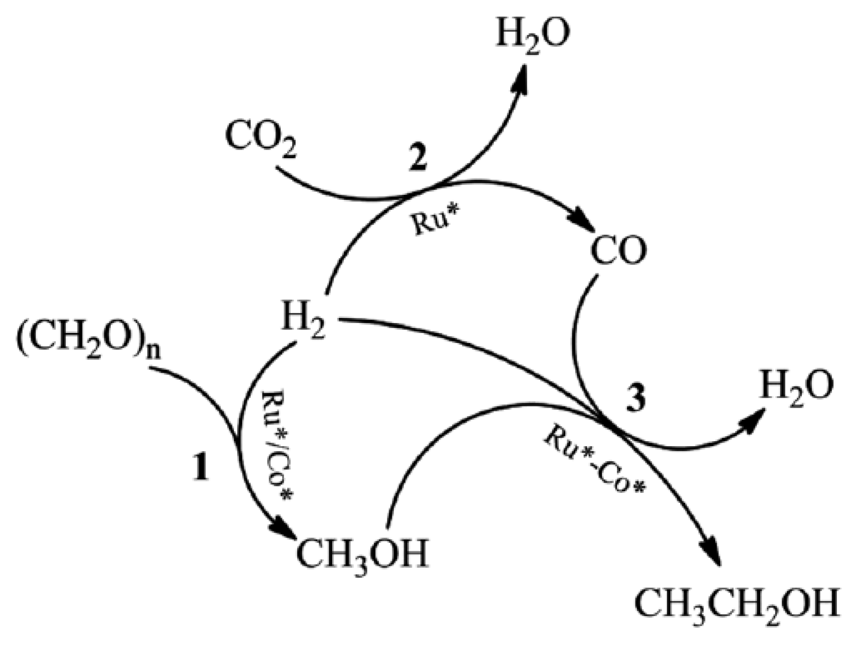
| Ru-Co | Metal | - | The production of ethanol from paraformaldehyde, CO2, and H2 | - | 50.9 C-mol% |
| WSe2-graphene | Metal | Ultra-sonication method | Photocatalytic reduction of CO2 into CH3OH | 5.0278 μmol g−1 h−1. | - |
| WSe2-graphene-TiO2 | Hybrid | Ultra-sonication method | CO2 reduction to CH3OH | 6.3262 μmol g−1 h−1 | - |
| hydroxide-mediated Cu | Metal | Hydroxide-mediated abrupt reaction interface | CO2 conversion to ethylene | 70% | 65% |
| CoPc/CNT | Hybrid | CO2 reduction to methanol | Dispersion process | 40% | - |
| Fe2O3@K2CO3 | Metal | CO2 conversion to olefins | Mortar mixing | 40% | 60% |
| Method | Set up | Purity | Cost in USD |
|---|---|---|---|
| Conventional arc discharge in vacuum | TIG power source, inert atmosphere, metal cabinet with water cooling system, automated process, and chemical purification | 80–95 wt% | 15 USD/gm |
| Chemical vapor deposition (CVD) | Furnace, inert atmosphere, metal catalyst | 95% | 40 USD/gm |
| Laser ablation | Laser source, furnace, inert atmosphere, metal catalyst–graphite composite | 20–80 wt% | Due to the high capital cost of the laser and the lower quantity of CNT after final purification, this method is not commercially viable. |
| Floating catalyst method | Tubular reactor, quartz tube, thermocouples, inert gas | 70–90 wt% | It requires a complicated set up. The cost of aromatic hydrocarbons is very high (Benzene: 44 USD/10 g). |
| Cyclic oxidation | Plant materials, ceramic reactor | No reports on purity | Even though the source materials are cheap, pre-treatment and heating takes longer duration in a high pressure vacuum chamber. Yield details are not available. |
| EDM process | Plasma sputtering unit, microelectric discharge apparatus, metal catalyst | No reports on purity | It requires costly equipment such as plasma-sputtering unit and microelectric discharge unit. Yield details are not mentioned. |
| Combustion process | Bunsen burner, liquefied butane, metal catalyst | No reports on purity | This method is simple but the yield seems to be much less compared to other methods (in mg). |
| Simplified arc discharge in air | Manual metal arc welding machine and chemical purification | 75–80 wt% | 3 USD/gm |
Disclaimer/Publisher’s Note: The statements, opinions and data contained in all publications are solely those of the individual author(s) and contributor(s) and not of MDPI and/or the editor(s). MDPI and/or the editor(s) disclaim responsibility for any injury to people or property resulting from any ideas, methods, instructions or products referred to in the content. |
© 2023 by the authors. Licensee MDPI, Basel, Switzerland. This article is an open access article distributed under the terms and conditions of the Creative Commons Attribution (CC BY) license (https://creativecommons.org/licenses/by/4.0/).
Share and Cite
Isahak, W.N.R.W.; Shaker, L.M.; Al-Amiery, A. Oxygenated Hydrocarbons from Catalytic Hydrogenation of Carbon Dioxide. Catalysts 2023, 13, 115. https://doi.org/10.3390/catal13010115
Isahak WNRW, Shaker LM, Al-Amiery A. Oxygenated Hydrocarbons from Catalytic Hydrogenation of Carbon Dioxide. Catalysts. 2023; 13(1):115. https://doi.org/10.3390/catal13010115
Chicago/Turabian StyleIsahak, Wan Nor Roslam Wan, Lina Mohammed Shaker, and Ahmed Al-Amiery. 2023. "Oxygenated Hydrocarbons from Catalytic Hydrogenation of Carbon Dioxide" Catalysts 13, no. 1: 115. https://doi.org/10.3390/catal13010115