Article

Monolayer CoMoS Catalysts on Hierarchically Porous Alumina Spheres as Bifunctional Nanomaterials for Hydrodesulfurization and Energy Storage Applications

by
Anabel D. Delgado
1,
Lorena Álvarez-Contreras
1,*,
Karen A. Beltrán
1,
Noé Arjona
2,
Minerva Guerra-Balcázar
3,
José Béjar
1 and
Alfredo Aguilar-Elguezabal
1
1
Centro de Investigación en Materiales Avanzados S.C. (CIMAV), Miguel de Cervantes No. 120, Complejo Industrial Chihuahua, Chihuahua C.P. 31136, Mexico
2
Centro de Investigación y Desarrollo Tecnológico en Electroquímica S.C., Pedro Escobedo, Querétaro C.P. 76703, Mexico
3
Facultad de Ingeniería, División de Investigación y Posgrado, Universidad Autónoma de Querétaro, Querétaro C.P. 76010, Mexico
*
Author to whom correspondence should be addressed.
Catalysts 2022, 12(8), 913; https://doi.org/10.3390/catal12080913
Submission received: 16 July 2022 / Revised: 5 August 2022 / Accepted: 8 August 2022 / Published: 19 August 2022
(This article belongs to the Section Catalytic Reaction Engineering)

Abstract

:
In this work, CoMoS catalysts were synthesized onto porous alumina spheres obtained using Pluronic P-123 (PS) or urea (US) and used as bifunctional nanomaterials for two energy applications: hydrodesulfurization and energy storage. For the first application, the catalysts were assessed in a hydrodesulfurization reactor using two model sulfur molecules, dibenzothiophene and 4,6-dimethyl dibenzothiophene, as well as feeding a heavy oil fraction. The results indicated that the spheres obtained by Pluronic P-123 allowed a greater dispersion degree of MoS2 slabs than US, indicating that the size and hierarchically porous structure of alumina spheres played a principal role as a booster of the HDS catalytic efficiency of DBT, 4,6 DMDBT and diesel fuel. Then, these catalysts were used for the electrocatalysis of the oxygen reduction and oxygen evolution reactions (ORR/OER), which take place in rechargeable Zn-air batteries. For the ORR, the CoMoS catalyst on PS in the presence of a conductive support (N-doped carbon nanotubes + graphene) displayed an overpotential of only 90 mV in comparison with Pt/C. Importantly, the chalcogenide enabled an increase in the stability, maintaining almost two times higher current retention than Pt/C for the ORR and IrO2/C for the OER. These results suggest that expended chalcogenides from the hydrodesulfurization industry can have a second life as co-catalysts for renewable energy storage systems, enabling a circular economy.

1. Introduction

The production of clean fuels for both renewable and traditional energy sources is essential to decrease contamination. The production of fossil fuels with an ultra-low sulfur content (<10 ppm) has challenges to overcome due to crude oil with a higher sulfur content and more refractory compounds nowadays being obtained, requiring that the hydrodesulfurization (HDS) catalysts have higher catalytic activity. Moreover, stringent environmental regulations increase the demand of high-quality refining products, establishing many requisites for the HDS capacity in refineries [1,2,3]. There are two ways to improve the fuel quality: first, through modifying the engineering behind the actual processes, resulting in a significant impact on investment, or by increasing the catalytic activity of materials for HDS, which is critical to obtaining ultra-clean fuels, this being a cost-effective solution. Hence, the design and development of highly active and multipurpose catalysts to produce clean fuels becomes a relevant field of study [4,5]. Conventionally, HDS catalysts are formed by molybdenum disulfide or tungsten disulfide particles, which are promoted using metals such as cobalt or nickel, and a support material, which is typically γ-alumina [1,4,5,6,7].
The support plays a key role for the active phase dispersion, and it also assists in the catalytic properties by inhibiting the crystalline phase growth or by enhancing the mass transport. Numerous studies dealing with new materials as catalytic supports have been reported, including those based on metal oxides Al2O3, TiO2 and ZrO2 [6,8,9], or in ordered mesoporous materials such as silica and alumina (MCM-41, SBA-15, KIT-6) [10,11]. Additionally, mixtures of metal oxides [12], and carbon materials [13] have also been reported as supports. All these materials exhibited promising properties for HDS. However, their application is restricted because of some of these present poor textural properties, whereas others have lower acidity, lower metal dispersion or lower hydrothermal stability in reaction conditions [14]. Nowadays, γ-alumina remains as the most widely used support in HDS catalysts. Nevertheless, the standard Al2O3 has some disadvantage such as a low surface area, wide pore size distribution, and low pore volume, limiting its catalytic performance and industrial applications. Recently, several investigations have been focused on developing new synthesis methods using a variety of surfactants (templates) and hydrolysis/poly-condensation conditions with the aim to promote the formation of different Al-O-network structures and morphologies, which can enhance the intrinsic properties of Al2O3 [15]. Moreover, the selectivity and activity of catalysts are strongly structure-, morphology- and support-composition dependent [16]. The morphology and pore size of the support determine the active species dispersion-degree; a suitable pore size reduces mass transfer problems during the catalytic reaction, which is crucial to increase the catalytic activity. Gao et al. [17] reported the study of HDS catalysts using SBA-15 supports with diverse morphologies such as spheres, rods, and hexagonal prisms. They found that the mesoporous SBA-15 silica with spherical morphologies exhibited the highest catalytic activity because of the presence of meso-channels and the high dispersion of active species. Dong et al. [18] prepared hierarchically structured alumina hollow microspheres with suitable textural characteristics as supports for HDS. The prepared catalysts reached higher activities than benchmarked NiMo/Al2O3 because the support assisted in achieving a greater surface area, appropriate acidity, and the highest active phases sulfidation and dispersion degree. In the work reported by Xie et al. [19], NiMo catalysts were prepared on porous Al-glycolate spheres obtained through alcoholysis or hydrolysis treatments. Then, they were used for the simultaneous HDS of DBT and hydrodenitrogenation (HDN) of naphthalene, obtaining conversions of greater than 70% for both compounds.
On the other hand, in recent years, molybdenum dichalcogenides (MoS2) have attracted substantial attention for energy conversion and storage applications due to the resemblance in free-energy of adsorbed atomic hydrogen existing with the Pt-group metals, and their variety in active sites, appropriate electronic band structure, high specific capacity, and excellent mechanical and thermal stability [20,21]. However, their low conductivity and limited surface area affects their performance as electrocatalysts [22,23,24]. To address the above issues, it has been found that defect engineering often allows the modulation of the electronic structure and generation of optimal multifunctional MoS2 materials [25,26]. For instance, Asadi et al. [27] demonstrated that MoS2 nanoflakes were potential cathode materials for lithium-air batteries. Dai et al. [21] reported that Co-doped MoS2 nanosheet catalysts showed excellent electrochemical performance due to their high exchange current density; low onset potential and excellent stability resulting from the structural and electronic modulation between MoS2 and Co ions; the abundance of defects in the active edge sites; and the good balance between active sites and electronic conductivity. Encouragingly, Wu’s group [28] presented a comprehensive overview of MoS2 and MoS2-based compounds in energy-related applications. Specifically, they systematically summarized the atomic structures and properties of the different MoS2 phases and the various synthesis methods to optimize their properties.
In general terms, the physio-chemical characteristics and the morphology of the support modulate the dispersion degree of the active phase and the metal-support interactions and, thus, the catalytic performance. It is worth mentioning that studies focused on the adjustment of the textural characteristics of alumina with specific morphology are scarce. Moreover, there are no reports on the electrochemical re-utilization of chalcogenides, which were first employed for HDS. These materials are known to have activity for electrochemical reactions such as the hydrogen evolution reaction (HER), the oxygen evolution reaction (OER), and oxygen reduction reaction (ORR) [29]. In addition, these oxygen reactions are especially important for the production of clean energy through energy storage systems such as metal-air batteries [30].
In the present study, porous alumina spheres were synthesized using Pluronic-123 (as a pore promoter) or urea (typically used as a precipitating agent) to analyze their effect on the textural properties. Then, a controlled amount of CoMoS was employed to form a CoMoS monolayer on the alumina supports. These materials were firstly used as catalysts for hydrocarbon HDS and, then, as electrochemical catalysts (electrocatalysts) for the oxygen reduction/evolution reactions (ORR/OER) as the cathode-side reactions in a metal-air battery. The results showed that the best performance for HDS, OER and ORR can be attributed to the formation of a Co-Mo-S phase with high dispersion, which effectively decreased the resistance to charge-transfer during the electrochemical evaluation. Additionally, it synergistically increased the structural and electronic modulations between MoS2 and Co, while increasing the active surface area, which is beneficial to achieve good results for HDS and batteries.

2. Results

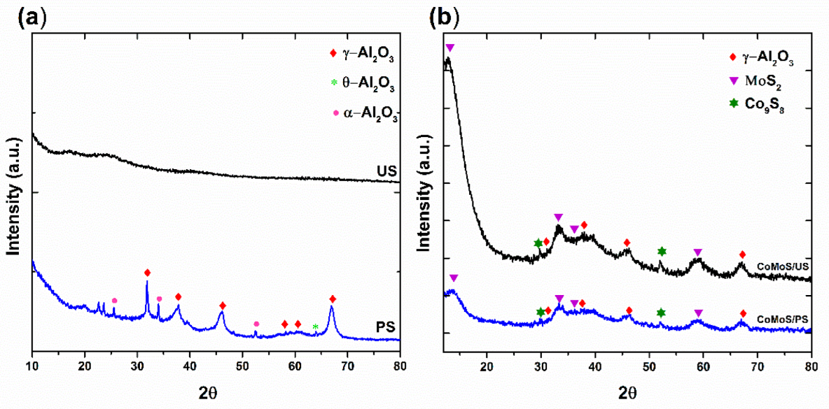
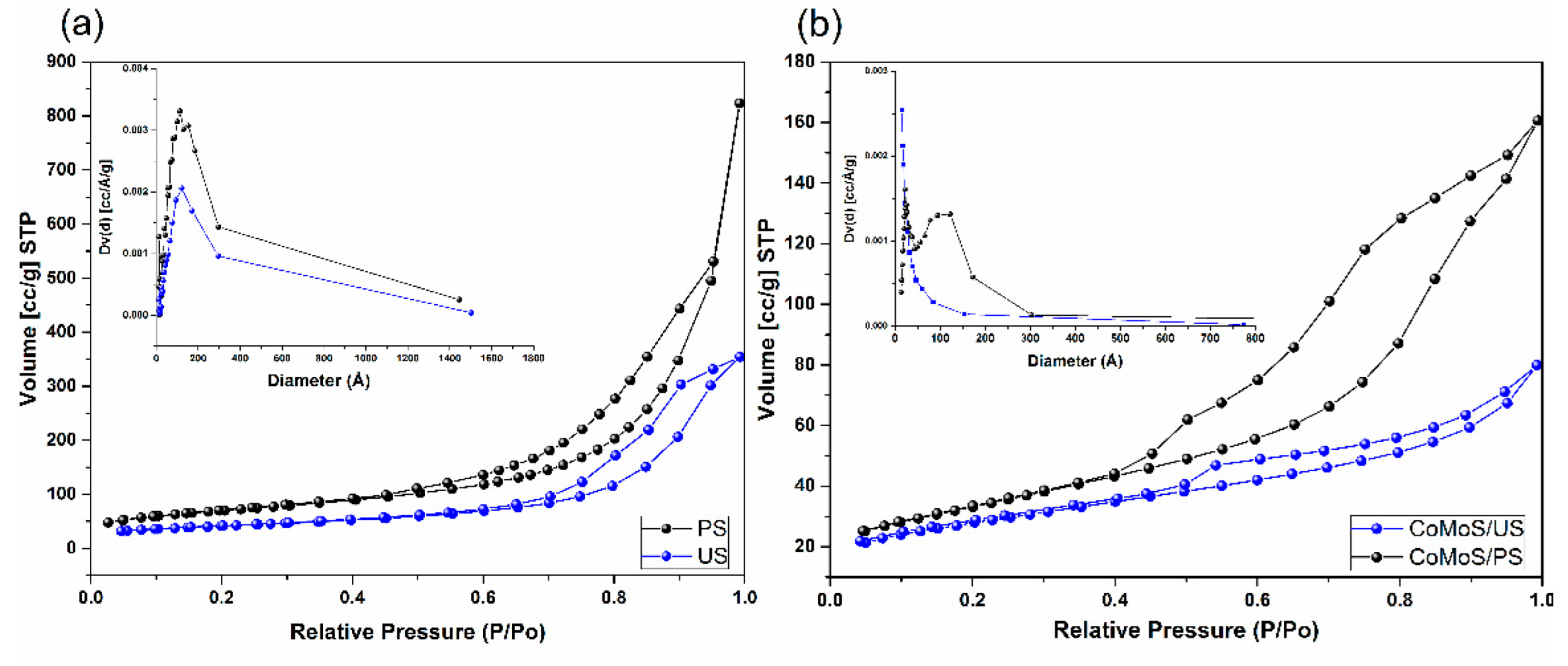
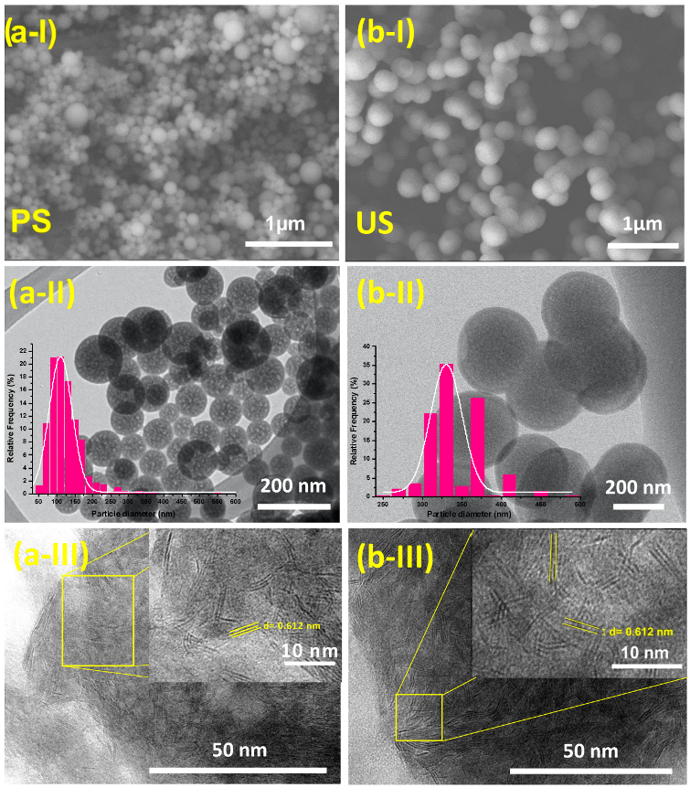
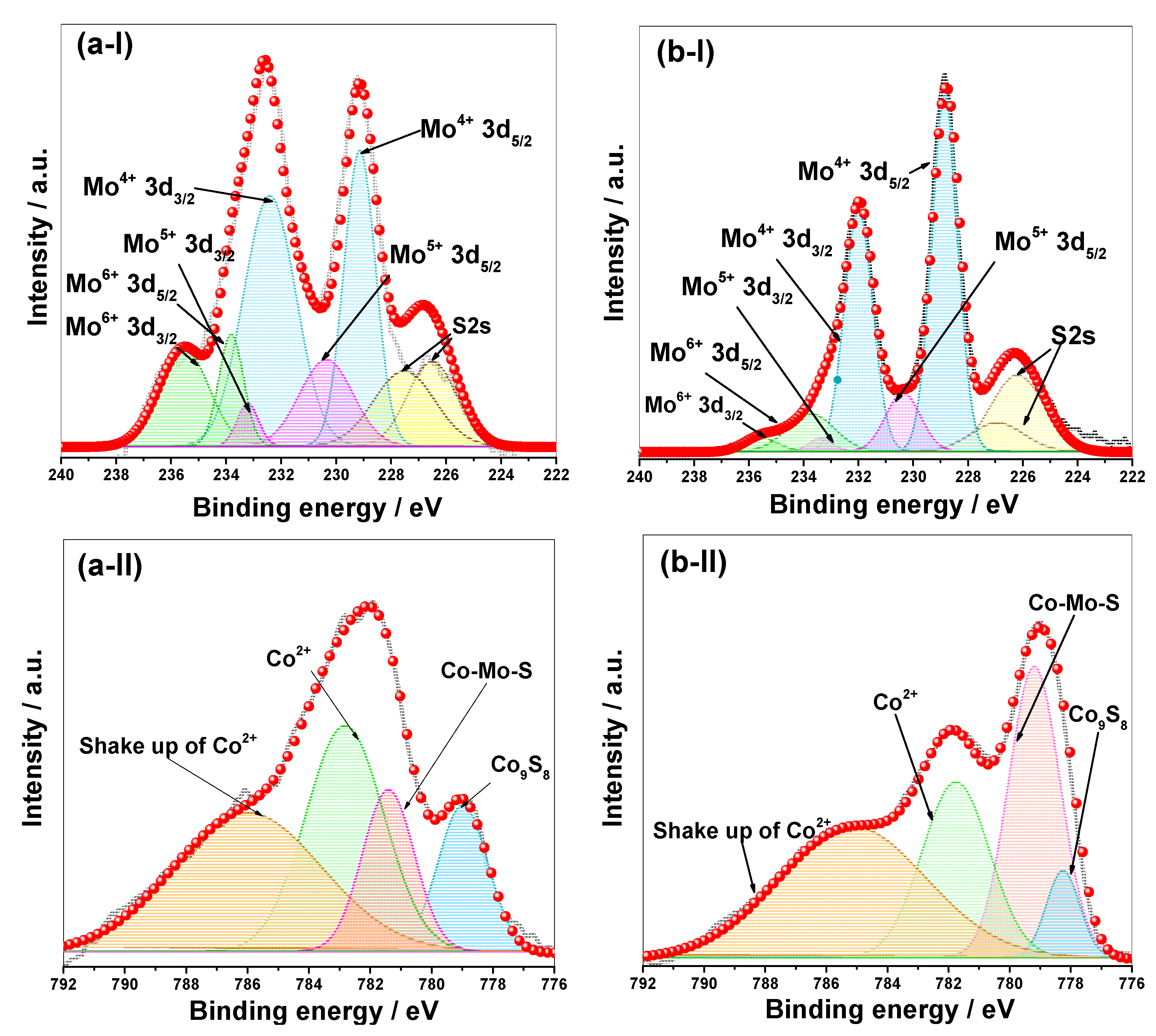
2.1. Physicochemical Characterization

The X-ray diffractograms showed structural differences between the alumina obtained using urea and P-123 (Figure 1a). The XRD pattern for Al2O3 synthesized with urea (US) exhibited a broad diffraction peak around 25° that can be ascribed to the amorphous nature of alumina spheres [31]. The XRD pattern of alumina spheres synthetized with Pluronic 123 (PS) exhibited a mixture of crystalline phases. Six diffraction peaks at 31.84°, 37.74°, 46.12°, 58.22°, 61.01° and 67.05° were indexed to the (220), (311), (400), (422), (511) and (440) planes of a cubic crystal structure (Fd-3m) of γ-Al2O3 transition phase (crystalline card # 00-050-0741), while the signal at 63.99° was associated to the (511) plane of a cubic crystal structure of θ-Al2O3 intermediate phase (card # 86-1410). In addition, the small peaks observed at 25.73°, 34.78° and 52.43° were indexed to the (012), (104) and (024) planes of a hexagonal crystal structure of α-Al2O3 phase (card # 46-1212). The X-ray results agree with those results reported by Norbert Eisenreich et al. [32], who found that γ- and θ-Al2O3 particles with sizes of a few micrometers in the first step are transformed to α-Al2O3.
XRD patterns were obtained after metal deposition on the alumina spheres and subsequent drying. The CoMoS catalysts exhibited the characteristic diffraction peaks of γ-Al2O3 crystalline phase (Figure 1b). The X-ray diffraction pattern of CoMoS/US displayed five diffraction peaks and, according to their positions, they confirmed the presence of γ-Al2O3 phase in the catalyst. In addition, the appearance of these well-defined diffraction peaks indicated that the amorphous phase of alumina was modified after the sulfidation treatment. Furthermore, the CoMoS/US and CoMoS/PS also displayed diffraction peaks at 14.02°, 32.86° and 58.8°, corresponding to the (002), (100) and (110) planes related with the hexagonal MoS2 phase (crystalline card #37-1492). The XRD patterns also revealed the presence of Co9S8 (crystalline card #00-019-0364) due to the small signals at 29.8°, 41.1° and 52.1°, which are related to the (311), (331) and (440) reflections (Figure 1b).
The N2-adsorption-desorption isotherms and pore size distributions of the supports and the CoMoS/US and CoMoS/PS catalysts are shown in Figure 2. In agreement with the IUPAC classification, the isotherms obtained for the supports corresponded to type IV, which are related to mesoporous materials. The hysteresis loop was associated with type H3, which was observed at P/P0 ranges of 0.5–1.0, representing macro-porous materials [33]. Nevertheless, the macro-porosity is attributed to the pores that are formed randomly due to the packing of spheres. The pore size distributions (Figure 2a insert) revealed that both US and PS supports have a wide pore size distribution with a peak centered around 16 and 20 nm for PS and US, respectively. The BET specific surface area (SBET) and pore structure metrics (size and volume) of the obtained US and PS supports are summarized in Table 1. SBET of 245 and 144 m2/g were obtained for PS and US supports, respectively. Consequently, a higher pore volume (1.27 cm3/g) was obtained for the PS support compared to that obtained for US (0.55 cm3/g). Thus, it is clear that the enhanced surface area found for the PS support can be related to its porous structure, which also explains the higher pore volume, being 2.3 times higher than that of the US support.
On the other side, the cobalt and molybdenum species impregnated and activated on the US and PS supports did not provide important modifications in the N2-adsorption–desorption isotherms (Figure 2b), confirming that the support initial pore structure was well-preserved in the catalysts. Nevertheless, as expected, a considerable decrease in the SBET, the nitrogen adsorbed volume and pore diameter was observed after metal deposition for both catalysts. The BET surface area, total pore volume and average pore diameter were reduced by 51.9, 76.4 and 48.1% to CoMoS/PS, and by 32.6, 78.2 and 87.5% to CoMoS/US. This suggests that the pore size distribution observed in the materials based on the US support could be attributed to an apparent porosity associated with the packing of the alumina spheres, which was hindered in the presence of the active phase.
The FE-SEM micrographs for US and PS supports are shown in Figure 3a-I,b-I, respectively. The PS support (Figure 3a-I) is composed of spherical-shaped particles displaying a narrow particle size distribution, whereas the US support (Figure 3b-I) also displays a spherical morphology. However, it has a wide particle size distribution. Although TEM micrographs confirmed the spherical shape for both supports (Figure 3a-II,b-II), the histograms for the particle size distribution of PS (Figure 3a-II, inset) and US (Figure 3b-II, inset), which were obtained by counting at least 500 particles for each material, indicated that the particle size of PS was 2.7 times smaller to that obtained for the US support (126 nm vs. 345 nm, Table 1). Moreover, the TEM micrographs revealed that the PS support spheres are constituted by the agglomeration of primary particles with sizes of less than 10 nm to form hierarchically porous alumina spheres (Figure 3a-II). In the case of the US support, the uniform spherical-shaped morphology consists of non-porous particles, as shown in the TEM micrograph (Figure 3b-II). On the other hand, the results of the EDS analysis are shown in Figure S1, where an atomic ratio of Co/(Co + Mo) close to 0.3 for both catalysts is observed, and a Mo load of 13.5 and 19.8% wt. for catalyst on US and PS, respectively, were obtained.
In order to analyze the active phase structure on the supports, TEM micrographs at high magnifications were taken (Figure 3a-III,b-III). Uniformly distributed MoS2 nanocrystals on the PS surface were observed (Figure 3a-III), while more agglomerated MoS2 nanocrystals were found on the US spheres (Figure 3b-III). Moreover, HRTEM micrographs were used to further investigate the detailed inner structures of bulk MoS2. The MoS2 particles stack in the range of 1 to 6 slabs with a length of less than 10 nm for the CoMoS/PS vs. 1 to 7 slabs with a length between 1 and 14 nm for the CoMoS/US. Table 2 summarizes the average slab length and average stacking number distributions of MoS2 slabs and Mo species dispersion (fMo) in the CoMoS catalysts. It can be noticed that the average slab length of the MoS2 over the CoMoS/PS catalysts was 4.5 ± 0.5 nm, whereas for the CoMoS/US catalysts it was 6.5 ± 0.5 nm. Concerning the average stacking degree, for both catalysts, it resulted in 2.2 ± 0.2 stacking. The values of fMo for CoMoS/PS and CoMoS/US were 0.26 and 0.24, respectively. These values confirmed an increment in the ratio of the Mo free-atoms to interact with reactants in the CoMoS catalyst supported on PS. The interplanar distance of the fringes is 0.612 nm, which is characteristic of the MoS2 slab [34,35]. Thus, TEM confirmed the activation of CoMo by H2S to form MoS2 slabs.
The XPS analysis provides information on the sulfidation state of the active phase over the surface of the catalysts. Figure 4 show the Mo3d and Co2p XPS spectra and their decomposition into different chemical species, according to previous works [35,36,37]. The two doublets encountered for Mo3d (Figure 4a-I,b-I) were adjusted with the characteristic distance of 3.2 eV and a ratio among spin-orbit doublets of 0.71. Three different oxidation degrees (Mo4+, Mo5+ and Mo6+, respectively) are reported for the sulfided catalysts [33,34,35]. (i) The binding energies at 228.9 ± 0.2 eV and 231.9 ± 0.3 eV are associated to Mo 3d5/2 and Mo 3d3/2, demonstrating the formation of the MoS2 phase. (ii) Binding energies at 230.3 ± 0.1 eV and 233.2 ± 0.1 eV are ascribed to the Mo 3d5/2 and Mo 3d3/2 of the oxysulfide phase. (iii) Binding energies at 233.7 ± 0.1 eV and 236.7 ± 0.1 eV are related to the Mo 3d5/2 and Mo 3d3/2 of an oxide phase, suggesting that either a fraction of Mo oxide remained after the process of sulfidation, or the sample quickly oxidized the previous XPS characterization. S2s contributions are reported. Nevertheless, they were not considered during the quantification of Mo species. The binding energies of the main contributions are reported in Table 3, and they agreed with the values reported in the literature, as previously mentioned.
The sulfidation degree of Mo species (Mosulfidation) was estimated using the equation: Mo4+/(Mo4+ + Mo5+ + Mo6+) [18,36]. The calculated contributions of the distinct Mo species onto the CoMoS/PS and CoMoS/US catalysts are presented in Table 3. It can be observed that the ratio of Mo4+ onto the CoMoS/PS catalyst was 78.01%, which was greater than the 62.81% for the CoMoS/US catalyst, indicating that the sulfidation of supported Mo oxide on Al2O3 spheres using P-123 was the most complete. This can be attributed to the higher dispersion of molybdenum atoms, which are more accessible during the sulfidation treatment. The Co 2p3/2 levels are shown in Figure 4a-II,b-II. The Co2p spectra were deconvoluted according to the literature [8,35,38] Therefore, the Co species in the CoMoS/US and CoMoS/PS catalysts are expected to belong to CoMoS, Co9S8 and cobalt oxide Co2+ [8,35,38,39]. The Co 2p3/2 signal centered at 778.2 ± 0.4 eV was associated to the Co9S8 phase. The Co 2p binding energy of CoMoS species was situated at 779.3 ± 0.5 eV, while the signal for cobalt oxide Co(II) was found at 781.6 ± 0.5 eV. The relative concentrations of different Co species in the CoMoS/US and CoMoS/PS catalysts are summarized in Table 3. It is clearly observed that the CoMoS/PS catalyst had more than twice the amount of CoMoS phase (30.35%) compared to the CoMoS/US catalyst (13.52%). The XPS results indicated that the hierarchically porous alumina spheres support not only assisted the generation of further MoS2 slabs, but also contributed to the interplay of the Mo with Co species, resulting in the creation of more CoMoS active phases in the CoMoS/PS catalyst, which could improve the catalytic performance.

2.2. Catalytic Evaluation of HDS of DBT in Batch Reactor

The HDS reactions of DBT were performed in a high-pressure batch reactor on the CoMoS catalysts with the objective of determining the influence of the textural parameters of the catalysts over the catalytic activity. Results from the conversion of DBT through HDS reactions after 5 h are presented in Table 4. The conversion of DBT obtained for CoMoS/PS and CoMoS/US was 65 and 50%, respectively. The lower catalytic yield achieved by the CoMoS/US catalyst can be explained in terms of dispersion of the active species on the carrier, for which a value of 0.24 was obtained, indicating that the active phase of MoS2 is more agglomerated in this support than in the PS support. Additionally, Table 4 shows the kinetic constants for the initial reaction rates assuming a pseudo first-order [40]. The best result was presented by the CoMoS/PS catalyst with a kinetic constant of 18.8 × 10⁻⁷ mol∙s−1∙g−1. The selectivity analysis given by the HYD/DDS ratio indicated that it was 0.17 and 0.79 for CoMoS/PS and CoMoS/US, respectively. The CoMoS/PS catalyst achieved the highest selectivity towards direct desulfurization (DDS), suggesting that the DDS route was predominant in the HDS reactions of dibenzothiophene.

2.3. Catalytic Evaluation of HDS of DBT, 4,6-DMDBT and Heavy Oil Fraction in High-Pressure Continuous Flow Tubular

To further evaluate the activity of the catalysts, two complementary HDS reactions were performed to discard the diffusional problems. All the reactions were carried out in a high-pressure continuous flow tubular stainless steel reactor with an inside diameter of 2.54 cm and a length of 60.96 cm. These HDS evaluations were performed with different feeds to the system (DBT, 4,6-DMDBT and diesel) under the conditions above described. The conversion results of the HDS of DBT, 4,6-DMDBT and diesel fuel are presented in Table 4. The experimental findings of the catalytic activity of the CoMoS catalysts indicated that for the two model molecules of sulfur, molybdenum deposited over PS is similarly active than molybdenum deposited in US. On CoMoS/PS, the DBT and 4,6-DMDBT molecules showed similar reactivity, as can be noted from Table 4, suggesting that the accessibility of these molecules to the active sites is similar, and that both reactions probably have the identical rate-limiting step [17]. The resemblance in activity also indicated that the difference in steric hindrance between molecules due to the additional methyl groups in the 4,6 DMDBT has no effect, likely because both molecules are absorbed by means of a II adsorption site type. These results agreed with those reported by Tuxen et al. [41], where they analyzed the adsorption mechanism of DBT and 4,6-DMDBT for model catalysts by means of a density functional theory (DFT) analysis and scanning tunneling microscopy (STM), concluding that DBT pi-adsorption can be found with an adsorption energy equal to 4,6-DMDBT. It should be noted that only the DFT results succeeded in presenting evidence for this adsorption type [41]. In the CoMoS/US catalyst, the reactivity of DBT and 4,6-DMDBT present similar behavior to that described for the CoMoS/PS catalyst. It is noted that both catalysts decrease the sulfur content to values below 10 ppm.
The catalysts were also analyzed in the HDS of diesel fuel. The conversion of diesel fuel for the HDS is shown in Table 4, finding a higher HDS degree with the CoMoS/PS catalyst (96.9%). The increase in HDS activity for the CoMoS/PS catalyst is potentially associated with increased hydrogenation activity, as already reported in a previous work [42]. Eijsbouts et al. reported that the size of MoS2 slabs directly influences the hydrogenation efficiency of the catalyst due to corner and edge sites, which are considered to be active sites for hydrogenation [43].
It is worth mentioning that the boosted catalytic activity is due to the addition of several factors that are found in the catalyst supported on PS. First, it is well-known that a determining aspect in the activity and selectivity of HDS catalysts is extremely linked to the presence of rim-edge sites, to which it attributes greater affinity for the adsorption of species such as H2 in the initial stages of the reaction and, thus, a more efficient desulfurization of hydrocarbons. Second, the presence of porosity in the PS support in a wide size range (hierarchical porous structure) can achieve a better mass transport, as has been reported in hierarchical alumina systems, which also allows more active sites and, hence, higher activity. Moreover, the small size of the porous sphere promotes a lower amount of deep porous that could not allow the access to active sites. All these factors enhanced the HDS catalytic efficiency of the CoMoS/PS catalyst compared to the conventional alumina-based catalysts. As shown in Table 5, CoMoS/PS displays competitive HDS catalytic efficiency compared with that of different reported catalysts.

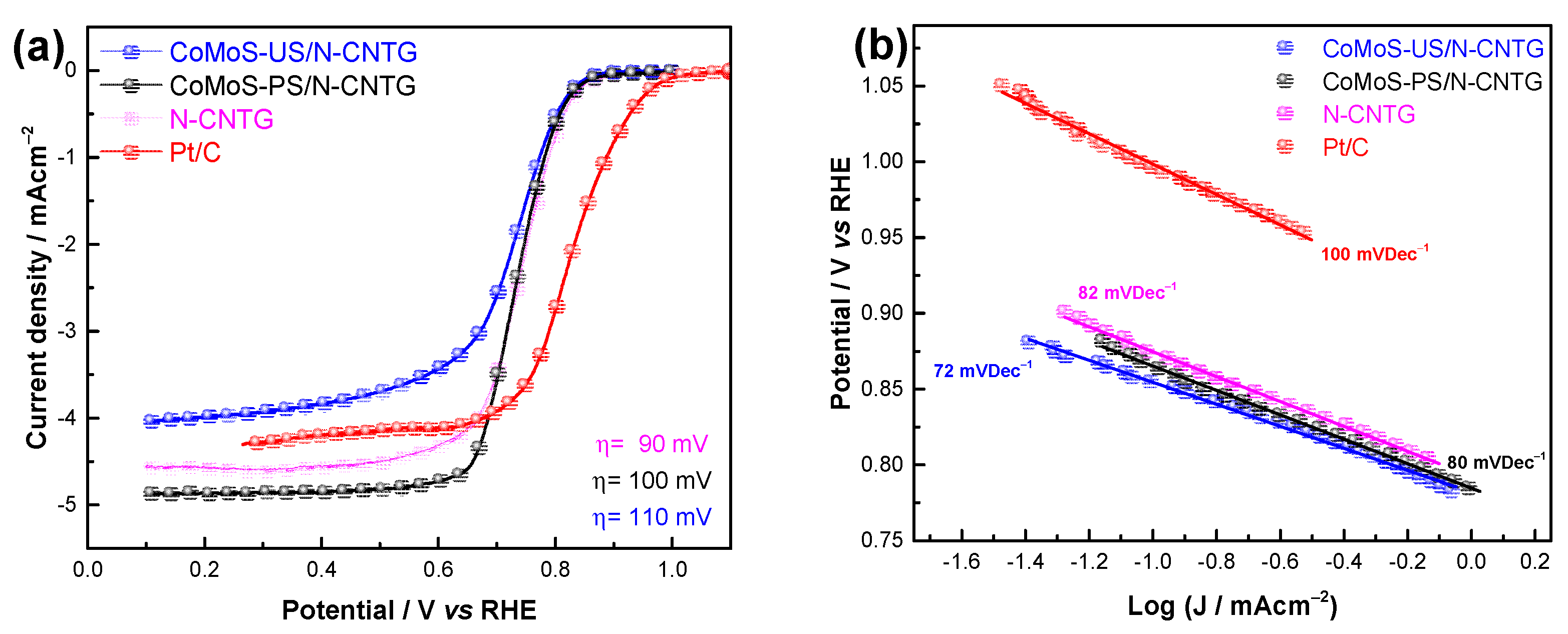
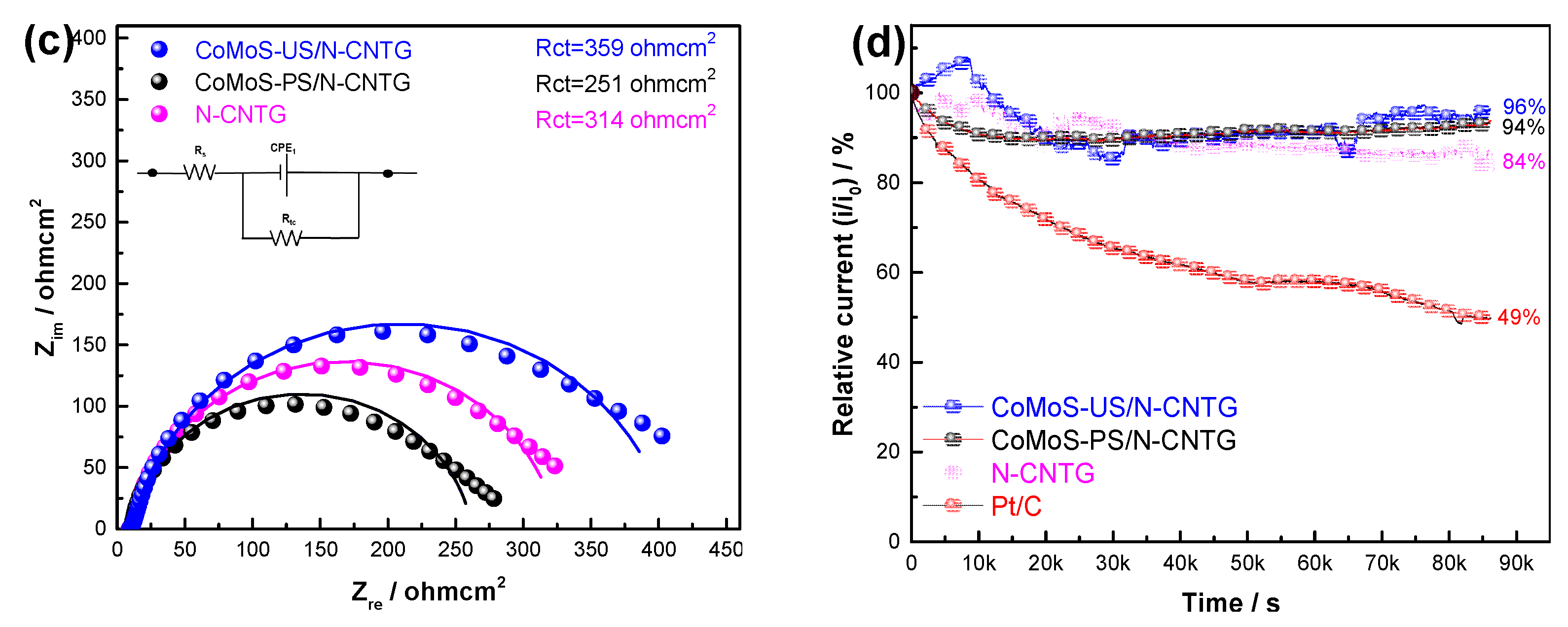
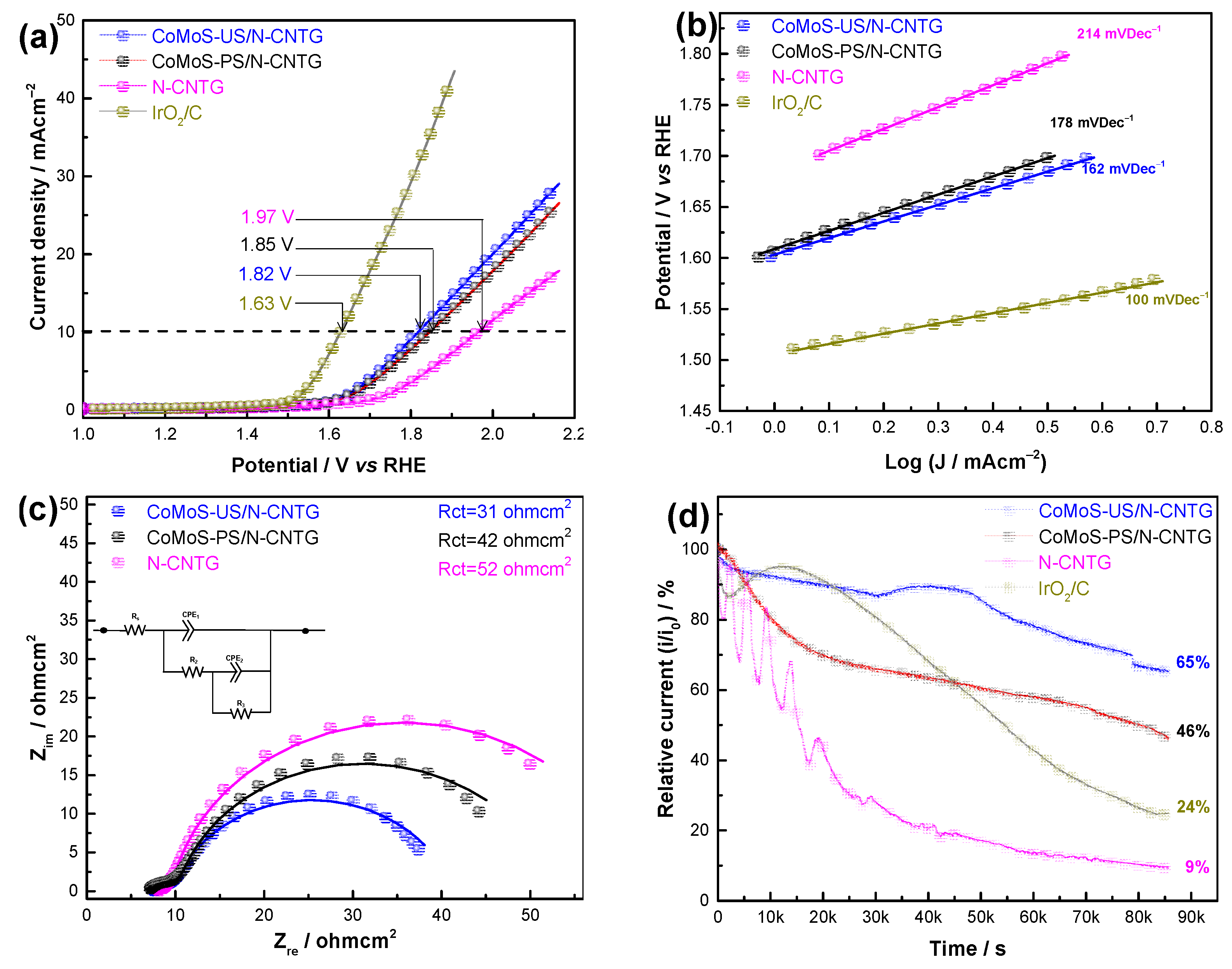
2.4. Electrochemical Evaluation for ORR/OER

The synthesized materials were electrochemically evaluated for the oxygen reduction and evolution reactions by linear scan voltammetry (LSV), using a rotating disk electrode to determine the potential re-utilization of expended chalcogenides for clean energy storage. The LSV curves for ORR are presented in Figure S1, which shows that these curves display the characteristic behavior of convective-controlled processes because a limiting current is achieved, and this increases with the increase in the rotatory speed (Figure S2a,b). Additionally, the Koutecky–Levich plots (insets) revealed a clear 4e pathway mechanism with a number of transferred electrons of 3.6 and four electrons for CoMoS/US and CoMoS/PS, respectively. Comparatively, Figure 5a displays the LSV curves at 1600 rpm for CoMoS materials, N-CNTG composite and benchmarked Pt/C. The onset potential for these materials was of 0.9 V and 1.0 V (V vs. RHE) for non-noble metallic catalysts and Pt/C, respectively. Moreover, the obtained half-wave potentials were 0.75, 0.74, 0.73 and 0.84 (V vs. RHE) for N-CNTG, CoMoS-PS/N-CNTG, CoMoS-US/N-CNTG and Pt/C, respectively. Concerning the limiting current density, CoMoS-PS/N-CNTG displayed the highest value, which, as mentioned before can be related to a better exposure of active sites.
The kinetics aspects were studied by a Tafel analysis (Figure 5b), where the tested materials exhibited Tafel slopes of 82, 72, 80 and 100 mV Dec−1 for N-CNTG, CoMoS-US/N-CNTG, CoMoS-PS/N-CNTG and Pt/C, respectively. According to the literature, under alkaline conditions, values near to 60 mVDec−1 are associated with a pseudo two-electrons reaction. Further, when the slope values are close to 120 mV Dec−1, the first electron is the rate-determining step (RDS), which is related to the oxygen adsorption as RDS [48]. In this sense, only the CoMoS-US/N-CNTG exhibits pseudo two-electrons behavior. Additionally, in order to calculate the resistance to charge transference (Rct), electrochemical impedance spectroscopy (EIS) was performed. The EIS spectra for the synthesized materials are displayed in Figure 5c where the lower Rct was obtained for the CoMoS-US/N-CNTG, according to the LSV curves. Additionally, it enables us to suggest the synergic effect between the N-CNTG support and CoMoS-PS material. Concerning the stability test (Figure 5d), this was improved by CoMoS-based materials, because both materials retained almost 100% of their initial current. On the contrary, N-CNTG and Pt/C lost 16% and 51% of their initial values, respectively.
Concerning the OER, Figure 6a exhibits the comparative LSVs for non-noble catalysts and IrO2/C. The CoMoS catalyst displayed onset potentials of only 100 mV higher than that of IrO2/C (1.61 V vs. RHE). Moreover, the N-CNTG support possesses the highest onset with 1.70 V. An important parameter during the OER is the potential required to achieve a current density of 10 mA cm−2. In this manner, potential values of 1.63, 1.82, 1.85 and 1.97 V were obtained for IrO2/C, CoMoS-US/N-CNTG, CoMoS-PS/N-CNTG and N-CNTG, respectively. Regarding the kinetic aspects, Tafel plots were calculated for the tested materials (Figure 6b), obtaining values of 214, 178, 162 and 100 mV Dec−1 for N-CNTG, CoMoS-US/N-CNTG, CoMoS-PS/N-CNTG and IrO2/C, respectively. The trend in Tafel slopes agrees with the LSV curves. Additionally, this trend in activity agreed with the Rct values obtained by EIS tests (Figure 6c), with the CoMoS-US/N-CNTG catalyst being the material showing the lower resistance to charge transference for the synthetized materials. As observed, the use of the chalcogenide decreased the potential in contrast to the carbonaceous support. However, the activity was lower to that presented by the reference material, indicating that further modifications are required to obtain a more suitable catalyst. Nonetheless, the use of alumina spheres enabled a superior stability (Figure 6d). The CoMoS-US/N-CNTG retained 65% of its initial current value. The PS material also provided stability, enabling it to retain 46% of its initial current, which is higher than the 24% that was obtained for IrO2/C and 9% for the carbonaceous support. As before mentioned, the CoMoS/PS material presented high activity for the production of clean fuels, as well as excellent activity/durability for the ORR. In the case of the OER, it is possible that the oxygen bubbles formed during the OER block the active sites of this catalyst by the effect of its morphology (Figure 3a-II), limiting the stability, while a 30 mV in potential difference is not electrochemically relevant. Nonetheless, despite the stability differences in the OER, the CoMoS/PS is the most suitable material for the clean production of fuels and the clean energy storage because of its high activity, selectivity and durability in comparison with the CoMoS supported on US alumina spheres.

3. Materials and Methods

3.1. Materials

Pluronic P123, Sigma-Aldrich; aluminum sulfate (Al2O12S3) 98.0%, Sigma-Aldrich; ethanol absolute, Sigma-Aldrich; ammonium hydroxide (NH4OH) 28.0–30.0%, Sigma-Aldrich; aluminum nitrate (Al(NO3)3·9H2O) 98%, Sigma-Aldrich; urea, CO(NH2)2 99.0–100.5%, Sigma-Aldrich; cobalt(II) nitrate hexahydrate (Co(NO3)2·6H2O) 98%, Sigma-Aldrich; Ammonium molybdate tetrahydrate ((NH4)6Mo7O24·4H2O) 99.98%, Sigma-Aldrich; dibenzothiophene (C12H8S) 98%, Alfa Aesar; decahydronaphthalene (C10H18) 99%, Sigma-Aldrich; 4,6-Dimethyldibenzothiophene (4,6-DMDBT,C14H12S) 97%, Sigma-Aldrich; glassy carbon (AMETEK®), potassium hydroxide (KOH) 85%, Sigma-Aldrich; commercial catalysts (Pt/C 20 wt%, IrO2/C 20 wt%), E-TEK; isopropyl alcohol 98%, Sigma-Aldrich; Nafion® 117 at 5 wt% in isopropyl alcohol, Sigma-Aldrich; N2 (Praxair 5.0, for research purpose); H2(Praxair 5.0, for research purpose); H2S(AOC 5.0, for research purpose), O2 (Praxair 5.0, for research purpose). The reagents were used as received without any further treatment.

3.2. Synthesis of Alumina Spheres

Porous alumina spheres were synthesized using the modified soft template method [49]. On a typical synthesis, 70 g of surfactant was dissolved in 700 mL of distilled water. Then, a solution of aluminum sulfate in ethanol with a concentration of 10.5 g of precursor/100 mL of ethanol was added at a 50 mL/hour rate. Subsequently, 15 mL of ammonium hydroxide was incorporated. The dissolution was left to stir for 24 h at 60 °C, then, the product was aged at 80 °C in a static atmosphere, e.g., without stirring (48 h). Hereafter, the solution was dried at 60 °C for 14 h. The calcination treatment was carried out in an air atmosphere at 700 °C for 3 h. For comparison purposes, no porous alumina spheres were synthesized following the methodology reported by Su et al. [50] using an aqueous solution of a mixture of aluminum sulfate and aluminum nitrate with an Al3+ concentration of 0.5 mmol/L and 10 mmol/L, respectively. Thereafter, a precipitating agent (urea) was incorporated into the dissolution. The mixture was strongly stirred for 30 min at 95 °C, then it was left in static conditions for 3 h. The recovered precipitate was first water-washed and then washed using ethanol. It was later dried at 60 °C and finally, calcined at 700 °C for 2 h.

3.3. Synthesis of Supported Catalysts

Mo and Co were loaded on the PS and US supports via the two-step incipient-wetness impregnation technique, obtaining CoMo/PS and CoMo/US catalysts precursors. The suitable amounts of metallic precursors required to form a monolayer of CoMoS2 phase were calculated based on the support’s specific surface area and an atomic ratio of Co/Co + Mo = 0.3. First a Co(NO3)2·6H2O aqueous solution was dropped on the support until a homogeneous paste was obtained. Afterward, the paste was dried at 60 °C for 2 h. After that, in a similar way, an aqueous solution of (NH4)6Mo7O24·4H2O was added on the Co pre-impregnated support and dried at the same conditions. Finally, the obtained materials were activated under a flow of 45 mL/minutes of a mixture of 15% H2S/H2 at 25 °C for 3 h, then heated up at 300 °C and left for 3 h. Lastly, the mixture was switched (10% N2/H2); the flow increased to 50 mL/minutes and was heated up at 400 °C, and the samples were kept for 2 h to obtain CoMoS/US and CoMoS/PS catalysts. The Mo contents were close 18.9 wt% and 13.3 wt% for CoMoS/PS and CoMoS/US, respectively.

3.4. Physicochemical Characterization

X-ray diffractograms were obtained using PANalytical X’Pert Pro apparatus operated at a 40 kV voltage and CuKα radiation within a 2θ interval between 10 and 80°, with a step size of 0.05° at a 100 s step time. The N2 adsorption–desorption analysis was obtained using Quantachrome NOVA 4200 at −196 °C. Before the measurement, the materials were outgassed at approximately 300 °C for 4 h under vacuum. The pore size distributions were determined by the adsorption branches of the isotherms by employing a Barrett–Joyner–Halenda (BJH) analysis. The Brunauer–Emmett–Teller (BET) model was utilized to estimate the specific surface area at a relative pressure (P/P0) range of 0.05 to 0.3. Surface and spheres morphology scanning electron microscopy micrographs were taken using a JEOL JSM–7401F field–emission scanning electron microscope (FE–SEM) operated at 3.0 kV. The size distribution was determined through the software Image Pro Plus version 6.0. A transmission electron microscopy (TEM) analysis was carried out using Hitachi™ 7700 with a 200 kV working voltage. In order to measure the morphological parameters from different particles, 800 MoS2 particles were considered, and the average slab length ( L ¯ ) and average number of layers for crystal ( N ¯ ) were determined according to Equations (1) and (2), respectively [34,35].
L ¯ = i = 1 n n i B i i = 1 n n i
N ¯ = i = 1 n n i A i i = 1 n n i
where B i is the length of the MoS2 nanoparticles, n i is the number of MoS2 crystal with length B i , and A i is the number of layers in slab i [36].
The average fraction of Mo atoms on the support surface, denoted as fMo, was statistically measured by dividing the total sum of the molybdenum atoms number situated on the edge (MoE) and corner sites (MoC) of the CoMoS nanoparticles, between the total number of molybdenum atoms (MoT). The fMo value is determined from Equation (3) [37]:
f M o = M o E + M o C M o T = i = 1 x 6 ( m i 1 ) i = 1 x ( 3 m i 2 3 m i + 1 )
where m i is the number of molybdenum atoms along one side of the MoS2 crystal calculated from its length (LS = 3.2 (2 m i − 1) Å), and x is the total number of slabs determined from the TEM images [37].
XPS measurements were performed on a Thermo Scientific Escalab 250Xi spectrometer using a monochromatic Al Kα (1486.6 eV) X-ray source. All binding energies (BE) were calibrated considering the reported position of the adventitious C1s (284.8 eV).

3.5. Catalytic Evaluation in Batch Reaction System

The catalytic activity was first evaluated in the HDS reaction of DBT, using a high-pressure batch reactor, Parr, model 4520, which was equipped with a magnetic stirrer to prevent the vortex formation, allowing a better gas mixture and diffusion into the liquid phase. The synthetic fuel (150 mL of dibenzothiophene in decahydronaphthalene, 4250 ppm of initial sulphur and 0.5 g of sulfided CoMoS/PS or CoMoS/US catalysts) was placed inside the reactor vessel. Prior to the reaction, the reactor was tightly closed, purged twice with H2, and pressurized up to 1.1 MPa of initial H2 pressure at room temperature. The sealed reactor was heated at 350 °C, reaching a final H2 pressure of 3.4 MPa. In order to track the reaction advance, liquid samples were collected every 30 min for 5 h. Then the samples were analyzed into a gas chromatograph (Perkin-Elmer, Waltham, MA, USA, Claus 500) fitted with an autosampler and packed column (OV-17), and coupled to a flame ionization detector (FID).
The hydrogenation (HYD) pathway/direct desulfurization (DDS) pathway ratio was used to determine the catalysts’ selectivity. The main reaction product from the DDS rout is biphenyl (BP), and tetrahydrobenzothiophene (THDBT), cyclohexylbenzene (CHB) and dicyclohexyl (DCH) are produced through the HYD pathway [51,52]. Thus, selectivity was evaluated from the product concentration ratio ([THDBT + CHB + DCH]/BP).

3.6. Catalytic Evaluation in a Continuous Reactor System

To determine the catalytic activity of the obtained catalysts, the HDS of DBT, 4,6-DMDBT and heavy oil fraction was evaluated in a continuous flow tubular reactor (Parr Instrument Company, Model 5403 with a 2.54 cm inside diameter X, 60.96 cm length, 3-zone split-tube furnace with gas feed system, cooling condenser and gas/liquid separator vessel), operated under down-flow mode. In a typical evaluation, 8 mL of CoMoS/PS or CoMoS/US catalyst (60 mesh) was placed in the steady temperature reactor site. The reaction conditions were fixed at 350 °C, 4.4 MPa, and the liquid hourly space velocity (LHSV) was 1 h−1 and a 300–400 H2-to-HC (hydrocarbon, DBT, 4,6-DMDBT or diesel) ratio (mL H2/mL HC) Decahydronaphthalene solutions with different initial sulfur contents, 4250 ppm of S and 500 ppm of S for DBT and 4,6-DMDBT, respectively, were prepared. The heavy oil fraction used was analyzed through the ASTM Standard D-4294-98, resulting in 1.562% of S (about 15,000 ppm of S). After 3 h, the steady state was attained, and the HDS products were condensed and collected. The reaction was performed for 12 h, obtaining samples every 2 h for further analysis. A significant decline in the catalytic performance was not recorded in the course of the testing. The S residual was surveyed on an Agilent 6850 gas chromatograph (GC) that was fitted with a sulfur chemiluminescence detector (SCD).

3.7. Electrocatalytic Evaluation

To study the electrocatalytic activity of CoMoS-US and CoMoS-PS materials, they were supported on an N-doped carbon nanotubes/graphene composite, which was synthesized using a similar method, as reported by [53,54], where the N-doping was achieved by thermal treatment using urea as nitrogen source [55,56]. The CoMoS-based materials were supported on an N-Doped composite in a 50–50 wt% ratio. The electrocatalytic evaluation was performed employing an AMETEK® VersaSTAT 3 Potentiostat/Galvanostat in a three-electrodes configuration cell, using a 0.196 cm2 glassy carbon as a working electrode, a Hg/HgO (4.24 M KOH) as a reference electrode and a graphite rod as a counter electrode. All the experiments were conducted using 0.1 M KOH solution as electrolyte. Synthesized materials and commercial catalysts were deposited onto glassy carbon through catalytic inks. The inks were prepared using isopropyl alcohol as dispersant and Nafion as the binder. The catalytic ink was prepared using 3 mg of material dispersed in 300 µL of isopropyl alcohol and 45 µL of Nafion for 30 min, then, 5 layers of 3µL were deposited on the polished glassy carbon. The total mass loading was 65µg/cm2 and 26 µg/cm2 for non-noble and noble catalysts, respectively. Electrochemical profiles were obtained by cyclic voltammetry using a scan rate of 20 mV/s in a potential window of −0.135 to 1.46 V vs. RHE (reversible hydrogen electrode). The total cycle number was 50, while a constant N2 bubbling was maintained during all the experiments. The electrocatalytic activity toward ORR and OER was studied using linear scan voltammetry (LSV) through the rotating disk electrode (RDE) technique. For ORR, LSVs were acquired in a potential range from 1 to 0.1 V vs. RHE for non-noble catalysts and 1.1 to 0.4 V vs. the RHE for Pt/C using a scan rate of 5 mV/s for both cases, varying the rotatory speeds (400, 600, 900, 1200, 1600, 2000 and 2500 rpm) and maintaining a constant O2 flow. In addition, the OER experiments were performed in a N2-rich solution using only 1600 rpm as the rotation speed, in a potential window from 1 to 2.16 V vs. RHE for CoMoS based materials and 1 to 1.9 V vs. RHE for IrO2/C at 5 mV/s. The catalytic stability was evaluated by the chronoamperometry technique: for ORR, the stability was determined using the half-wave potential of each material, maintaining a rotation speed of 1600 rpm and constant oxygen bubbling for 24 h. On the other hand, OER stability was evaluated at the potential where each material displays 10 mA/cm2, maintaining a rotation speed of 1600 rpm and constant nitrogen bubbling for 24 h. Then, the current was normalized by the initial value at t = 0. Finally, for a better understanding of N-CNTG and CoMoS materials interaction, electrochemical impedance spectroscopy was performed using the onset potential of each material for both reactions (ORR and OER), and a frequency range from 100 kHz to 0.1 Hz.

4. Conclusions

The alumina spheres were synthesized via combined sol-gel and soft-templating techniques, employing alkoxide free precursors. After the deposition of cobalt and molybdenum active species, the form of the alumina spheres remained; however, differences were found in the quantity of accessible active sites. The CoMoS/PS catalyst had better dispersion and stacking numbers of MoS2 nanocrystal, which supply more active sites for the HDS reactions of DBT, 4,6 DMDBT and diesel fuel than the CoMoS/US catalyst. Between these two catalysts, the catalyst (CoMoS/PS) showed a higher dispersion of Mo and a higher kinetic constant, as well as higher DBT conversion and sulfur removal than the catalyst CoMoS/US, despite the lower content of molybdenum and cobalt. The high HDS activity of the catalyst CoMoS/PS could conceivably relate to the capability of its surface to be reached by catalyst precursors without diffusion problems. This accessibility remained for most of the active sites that were formed after the sulfidation treatment. These results demonstrate that the amount of active phase that must be used for a support has to be determined based not only on its surface area, but also considering the characteristics of its porosity. Moreover, the electrochemical evaluation of these chalcogenides indicated that they are suitable electrochemical catalysts because the stability increased almost two times with regards to the benchmarked noble metals (Pt/C and IrO2/C). The CoMoS/PS material presented high activity for the production of clean fuels, as well as excellent activity/durability for the ORR. Due to this, CoMoS/PS resulted to be the most suitable material for the clean production of fuels and clean energy storage. In this manner, the sustainable re-use of expended chalcogenides for clean energy storage is attractive for a circular economy.

Supplementary Materials

The following supporting information can be downloaded at: https://www.mdpi.com/article/10.3390/catal12080913/s1, Figure S1: TEM images of the (a) CoMoS/US, (b) CoMoS/PS and EDS analysis of the catalysts (inset). Figure S2: Linear scan voltammetries and K-L plots (insets) of (a) N-CNTG and (b) Benchmarked Pt/C.

Author Contributions

Conceptualization, A.D.D., L.Á.-C. and N.A.; methodology, A.D.D., K.A.B. and J.B.; formal analysis, A.D.D., L.Á.-C., M.G.-B., N.A. and A.A.-E.; investigation, A.D.D.; K.A.B. and J.B.; writing—review and editing, A.D.D., L.Á.-C., J.B., M.G.-B., N.A and A.A.-E.; project administration, A.D.D. and L.Á.-C.; funding acquisition, L.Á.-C. All authors have read and agreed to the published version of the manuscript.

Funding

This research was funded by the Mexican National Council for Science and Technology (CONACYT) through projects grant #39569 and # 319645 and Centro de Investigación en Materiales Avanzados S., C. (CIMAV) through the internal project grant #. PI-22-10/2022.

Data Availability Statement

Not applicable.

Acknowledgments

The authors acknowledge the technical support of Karla Campos, Luis Gerardo Silva Vidaurri, Raul Ochoa and Luis de la Torre for physicochemical characterization.

Conflicts of Interest

The authors declare no conflict of interest.

References

  1. Huirache-Acuña, R.; Zepeda, T.A.; Vázquez, P.J.; Rivera-Muñoz, E.M.; Maya-Yescas, R.; Pawelec, B.; Alonso-Núñez, G. The use of inorganic Al-HMS as a support for NiMoW sulfide HDS catalysts. Inorg. Chim. Acta 2021, 524, 120450. [Google Scholar] [CrossRef]
  2. Asadi, A.A.; Royaee, S.J.; Alavi, S.M.; Bazmic, M. Ultra-deep hydrodesulfurization of cracked and atmospheric gasoil blend: Direct and interactive impacts of support composition, chelating agent, metal and promoter loadings. Fuel Process. Technol. 2019, 187, 36–51. [Google Scholar] [CrossRef]
  3. Yu, K.; Kong, W.; Zhao, Z.; Duan, A.; Kong, L.; Wang, X. Hydrodesulfurization of dibenzothiophene and 4,6-dimethyldibenzothiophene over NiMo supported on yolk-shell silica catalysts with adjustable shell thickness and yolk size. J. Catal. 2022, 410, 128–143. [Google Scholar] [CrossRef]
  4. Wang, G.; Chena, G.; Xie, W.; Wang, W.; Bing, L.; Zhang, Q.; Fu, H.; Wang, F.; Han, D. Three-dimensionally ordered macroporous bulk catalysts with enhanced catalytic performance for thiophene hydrodesulfurization. Fuel Process. Technol. 2020, 199, 106–268. [Google Scholar] [CrossRef]
  5. Amaya, S.L.; Alonso-Núñez, G.; Díaz De León, J.N.; Fuentes, S.; Chavarría, A.E. Synthesis and characterization of metal oxides complexes with potential application in HDS reactions. Mater. Lett. 2021, 291, 129562. [Google Scholar] [CrossRef]
  6. Yue, S.; Xu, D.; Sheng, Y.; Yin, Z.; Zou, X.; Wang, X.; Zou, X.; Lu, X. One-step synthesis of mesoporous alumina-supported molybdenum carbide with enhanced activity for thiophene hydrodesulfurization. J. Environ Chem. Eng. 2021, 9, 105693. [Google Scholar] [CrossRef]
  7. Han, D.; Li, Q.; Wang, E.; Xie, W.; Chen, G.; Zhang, Q.; Bing, L.; Wang, F.; Fu, H.; Wang, G. The evolution of NiMo unsupported catalysts with 3DOM structure for thiophene hydrodesulfurization. Catal. Today 2022. [Google Scholar] [CrossRef]
  8. Garcia, E.D.; Chen, J.; Oliviero, E.; Oliviero, L.; Maugéa, F. New insight into the support effect on HDS catalysts: Evidence for the role of Mo-support interaction on the MoS2 slab morphology. Appl. Catal. B Environ. 2020, 260, 117975. [Google Scholar] [CrossRef]
  9. Mendoza-Nieto, J.A.; Vizueth-Montes de Oca, A.; Calzada, L.A.; Klimova, T.E. Trimetallic NiMoW and CoMoW catalysts supported on SBA-15 modified with titania or zirconia for deep hydrodesulfurization. Catal. Today 2021, 360, 78–89. [Google Scholar] [CrossRef]
  10. Shafiq, I.; Shafique, S.; Akhter, P.; Yang, W.; Hussain, M. Recent developments in alumina supported hydrodesulfurization catalysts for the production of sulfur-free refinery products: A technical review. Catal. Rev. 2022, 64, 1–86. [Google Scholar] [CrossRef]
  11. Huirache-Acuña, R.; Pérez-Ayala, E.; Cervantes-Gaxiola, M.E.; Alonso-Nuñez, G.; Zepeda, T.A.; Rivera-Muñoz, E.M.; Pawelec, B. Dibenzothiophene hydrodesulfurization over ternary metallic NiMoW/Ti-HMS mesoporous catalysts. Catal. Commun. 2021, 155, 106316. [Google Scholar] [CrossRef]
  12. Obeso-Estrella, R.; Pawelec, B.; Mota, N.; Flores, L.; Melgoza, J.M.Q.; Yocupicio-Gaxiola, R.I.; Zepeda, T.A. Elucidating the mechanisms of titanium–induced morphological and structural changes in catalysts on mesoporous Al2O3–TiOx mixed oxides: Effect of non–stoichiometric TiOx phase. Microporous Mesoporous Mater. 2022, 339, 111991. [Google Scholar] [CrossRef]
  13. Chen, Z.; Liu, Y.; Chen, J.; Zhao, Y.; Jiang, T.; Zhao, F.; Yu, J.; Yang, H.; Yang, F.; Xu, C. Synthesis of alumina-nitrogen-doped carbon support for CoMo catalysts in hydrodesulfurization process. Chin. J. Chem. Eng. 2022, 40, 392–402. [Google Scholar] [CrossRef]
  14. Mahmoudabadi, Z.S.; Rashidi, A.; Tavasoli, A. Synthesis of MoS2 quantum dots as a nanocatalyst for hydrodesulfurization of Naphtha: Experimental and DFT study. J. Environ. Chem. Eng. 2020, 8, 103736. [Google Scholar] [CrossRef]
  15. Zhao, J.; Han, P.; Li, J.; Hu, X.; Guo, A.; Yang, S.; Du, H. Compound surfactant-based emulsion method for the preparation of high-porosity alumina microspheres. Ceram. Int. 2022, 48, 23111–23118. [Google Scholar] [CrossRef]
  16. Delgado, A.D.; Contreras, L.A.; Beltran, K.A.; Elguezabal, A.A. Effect of the SiO2 support morphology on the hydrodesulfurzation performance of NiMo catalysts. J. Mater. Res. 2018, 33, 3646–3655. [Google Scholar] [CrossRef]
  17. Gao, D.; Duan, A.; Zhang, X.; Zhao, Z.; Li, J.; Wang, H. Synthesis of NiMo Catalysts supported on mesoporous Al-SBA-15 with different morphologies and their catalytic performance of DBT HDS. Appl. Catal. B Environ. 2015, 165, 269–284. [Google Scholar] [CrossRef]
  18. Dong, Y.; Xu, Y.; Zhang, Y.; Lian, X.; Yi, X.; Zhou, Y.; Fang, W. Synthesis of hierarchically structured alumina support with adjustable nanocrystalline aggregation towards efficient hydrodesulfurization. Appl. Catal. A Gen. 2018, 165, 30–39. [Google Scholar] [CrossRef]
  19. Xie, K.; Fang, Y.; Liu, B.; Li, C. Enhanced catalytic activity of monodispersed porous Al2O3 colloidal spheres with NiMo for simultaneous hydrodesulfurization and hydrogenation. RSC Adv. 2018, 8, 18059–18066. [Google Scholar] [CrossRef]
  20. Morales-Guio, C.G.; Hu, X.L. Amorphous Molybdenum Sulfides as Hydrogen Evolution Catalysts. Acc. Chem. Res. 2014, 47, 2671–2681. [Google Scholar] [CrossRef]
  21. Dai, X.; Du, K.; Li, Z.; Liu, M.; Ma, Y.; Sun, H.; Zhang, X.; Yang, Y. Co–doped MoS2 Nanosheets with Dominant CoMoS Phase Coated on Carbon as an Excellent Electrocatalyst for Hydrogen Evolution. ACS Appl. Mater. Interfaces 2015, 49, 27242–27253. [Google Scholar] [CrossRef] [PubMed]
  22. Zhang, N.; Gan, S.Y.; Wu, T.S.; Ma, W.G.; Han, D.X.; Niu, L. Growth Control of MoS2 Nanosheets on Carbon Cloth for Maximum Active Edges Exposed: An Excellent Hydrogen Evolution 3D Cathode. ACS Appl. Mater. Interfaces 2015, 7, 12193–12202. [Google Scholar] [CrossRef] [PubMed]
  23. Zou, X.X.; Zhang, Y. Noble Metal–Free Hydrogen Evolution Catalysts for Water Splitting. Chem. Soc. Rev. 2015, 44, 5148–5180. [Google Scholar] [CrossRef]
  24. Zheng, X.L.; Xu, J.B.; Yan, K.Y.; Wang, H.; Wang, Z.L.; Yang, S.H. Space–Confined Growth of MoS2 Nanosheets within Graphite: The Layered Hybrid of MoS2 and Graphene as an Active Catalyst for Hydrogen Evolution Reaction. Chem. Mater. 2014, 26, 2344–2353. [Google Scholar] [CrossRef]
  25. Zhou, W.J.; Zhou, K.; Hou, D.M.; Liu, X.J.; Li, G.Q.; Sang, Y.H.; Liu, H.; Li, L.G.; Chen, S.W. Three-Dimensional Hierarchical Frameworks Based on MoS2 Nanosheets Self-Assembled on Graphene Oxide for Efficient Electrocatalytic Hydrogen Evolution. ACS Appl. Mater. Interfaces 2014, 6, 21534–21540. [Google Scholar] [CrossRef] [PubMed]
  26. Zhang, Y.; Zhang, Y.; Zhang, H.; Bai, L.; Hao, L.; Ma, T.; Huang, H. Defect engineering in metal sulfides for energy conversion and storage. Coord. Chem Rev. 2021, 448, 214147. [Google Scholar] [CrossRef]
  27. Asadi, M.; Kumar, B.; Liu, C.; Phillips, P.; Yasaei, P.; Behranginia, A.; Zapol, P.; Klie, R.F.; Curtiss, L.A.; Salehi-Khojin, A. Cathode Based on Molybdenum Disulfide Nanoflakes for Lithium−Oxygen Batteries. ACS Nano 2016, 10, 2167–2175. [Google Scholar] [CrossRef]
  28. Wu, J.; Ciucci, F.; Kim, J.-K. Molybdenum sulfide-based nanomaterials for rechargeable batteries. Chem. Eur. J. 2020, 26, 6296–6319. [Google Scholar] [CrossRef]
  29. Zhao, J.; Wang, J.; Chen, Z.; Ju, J.; Han, X.; Deng, Y. Metal Chalcogenides: An Emerging Material for Electrocatalysis. APL Mater. 2021, 9, 050902. [Google Scholar] [CrossRef]
  30. Yang, Q.; Liu, R.; Gao, J.; Liu, Y.; Hu, S.; Song, H.; Zhang, S. Boosting the Oxygen Reduction Reaction in Zn-Air Batteries via a Uniform Trace N-Doped Carbon-Based Pore Structure. ACS Appl. Energy Mater. 2022, 5, 1041–1051. [Google Scholar] [CrossRef]
  31. Boretskaya, A.; Il’yasov, I.; Egorova, S.; Popov, A.; Lamberov, A. Modification of a phase-inhomogeneous alumina support of a palladium catalyst. Part I: Effect of the amorphous phase on the textural and acidic characteristics of alumina and methods for controlling its phase homogeneity. Mater. Today Chem. 2020, 18, 18059–18066. [Google Scholar] [CrossRef]
  32. Eisenreich, N.; Fietzek, H.; Juez-Lorenzo, M.M.; Kolarik, V.; Koleczko, A.; Weiser, V. On the Mechanism of Low Temperature Oxidation for Aluminum Particles down to the Nano-Scale. Propellants Explos. Pyrotech. 2004, 29, 137–145. [Google Scholar] [CrossRef]
  33. Thommes, M.; Kaneko, K.; Neimark, A.V.; Olivier, J.P.; Rodriguez-Reinoso, F.; Rouquerol, J.; Sing, K.S. Physisorption of gases, with special reference to the evaluation of surface area and pore size distribution (IUPAC Technical Report). Pure Appl. Chem. 2015, 87, 1051–1069. [Google Scholar] [CrossRef]
  34. Liu, H.; Yin, C.; Liu, B.; Li, X.; Li, Y.; Chai, Y.; Liu, C. Effect of calcination temperature of unsupported NiMo catalysts on the hydrodesulfurization of dibenzothiophene. Energy Fuels 2014, 28, 2429–2436. [Google Scholar] [CrossRef]
  35. Yu, Q.; Zhang, L.; Guo, R.; Sun, J.; Fu, W.; Tang, T.; Tang, T. Catalytic performance of CoMo catalysts supported on mesoporous ZSM-5 zeolite-alumina composites in the hydrodesulfurization of 4,6-dimethyldibenzothiophene. Fuel Process. Technol. 2017, 159, 76–87. [Google Scholar] [CrossRef]
  36. Han, W.; Nie, H.; Long, X.; Li, M.; Yang, Q.; Li, D. Effects of the support BrØnsted acidity on the hydrodesulfurization and hydrodenitrogention activity of sulfided NiMo/Al2O3 catalysts. Catal. Today 2017, 292, 58–66. [Google Scholar] [CrossRef]
  37. Zhou, W.; Liu, M.; Zhou, Y.; Wei, Q.; Zhang, Q.; Ding, S.; Zhang, Y.; Yu, T.; You, Q. 4,6-dimethyldibenzothiophene hydrodesulfurization on nickel-modified USY- Supported NiMoS catalysts: Effects of modification method. Energy Fuels 2017, 31, 7445–7455. [Google Scholar] [CrossRef]
  38. Beltrán, K.A.; Alvarez-Contreras, L.; Delgado, A.D.; Leyva-Porras, C.C.; Aguilar-Elguezaba, L.A. Effect of pre-activation treatment temperature on hydrodesulfurization catalytic activity of CoMoS/KIT-6. Catal. Today 2021, 360, 106–115. [Google Scholar] [CrossRef]
  39. Klimov, O.V.; Nadeina, K.A.; Vatutina, Y.V.; Stolyarova, E.A.; Danilova, I.G.; Gerasimov, E.Y.; Prosvirin, I.P.; Noskov, A.S. CoMo/Al2O3 hydrotreating catalysts of diesel fuel with improved hydrodenitrogenation activity. Catal. Today 2018, 307, 73–83. [Google Scholar] [CrossRef]
  40. Dorneles de Mello, M.; De Almeida Braggio, F.; Da Costa Magalhães, B.; Zotin, J.L.; Da Silva, M.A.P. Kinetic modeling of deep hydrodesulfurization of dibenzothiophenes on NiMo/alumina catalysts modified by phosphorus. Fuel Process. Technol. 2018, 177, 66–74. [Google Scholar] [CrossRef]
  41. Tuxen, A.K.; Fuchtbauer, H.G.; Temel, B.; Hinnemann, B.; Topsoe, H.; Knudsen, K.G.; Besenbacher, F.; Lauritsen, J.V. Atomic-scale insight into adsorption of sterically hindered dibenzothiophenes on MoS2 and Co–Mo–S hydrotreating catalysts. J. Catal. 2012, 295, 146–154. [Google Scholar] [CrossRef]
  42. Yin, H.; Liu, X.; Zhou, T.; Lin, A. Effect of preparation method of nanosized zeolite HY-Al2O3 composite as NiMo catalyst support on diesel HDS. J. Fuel Chem. Technol. 2018, 46, 950–956. [Google Scholar] [CrossRef]
  43. Eijsbouts, S.; Heinerman, J.J.L.; Elzerman, H.J.W. MoS2 structures in high-activity hydrotreating catalysts: I. Semi-quantitative method for evaluation of transmission electron microscopy results. Correlations between hydrodesulfurization and hydrodenitrogenation activities and MoS2 dispersion. Appl. Catal. A Gen. 1993, 105, 53–68. [Google Scholar] [CrossRef]
  44. Kabe, T.; Qian, W.; Ogawa, S.; Ishihara, A. Mechanism of hydrodesulfurization of dibenzothiophene on CoMoAl2O3 and CoAl2O3 catalyst by the use of radioisotope 35S tracer. J. Catal. 1993, 143, 239–248. [Google Scholar] [CrossRef]
  45. Choi, K.H.; Kunisada, N.; Korai, Y.; Mochida, I.; Nakano, K. Facile ultra-deep desulfurization of gas oil through two-stage or -layer catalyst bed. Catal. Today 2003, 86, 277–286. [Google Scholar] [CrossRef]
  46. Morales-Ortuño, J.C.; Klimova, T.E. Development of new hydrodesulfurization NiMo catalysts supported on Al2O3-TiSBA-15 hybrid materials. Fuel 2017, 15, 99–109. [Google Scholar] [CrossRef]
  47. Miño, A.; Lancelot, C.; Blanchard, P.; Lamonier, C.; Rouleau, L.; Roy-Auberger, M.; Royer, S.; Payen, E. Strategy to produce highly loaded alumina supported CoMo-S catalyst for straight run gas oil hydrodesulfurization. Appl. Catal. A Gen. 2017, 530, 145–153. [Google Scholar] [CrossRef]
  48. Shinagawa, T.; Garcia-Esparza, A.T.; Takanabe, K. Insight on Tafel slopes from a microkinetic analysis of aqueous electrocatalysis for energy conversion. Sci. Rep. 2015, 5, 13801. [Google Scholar] [CrossRef]
  49. Wu, Y.; Xu, P.; Li, L. Synthesis of alumina with coarse particle by precipitating aluminum ammonium sulfate solution with ammonia. Adv. Powder Technol. 2016, 27, 124–129. [Google Scholar] [CrossRef]
  50. Su, X.; Chen, S.; Zhou, Z. Synthesis and characterization of monodisperse porous α-Al2O3 nanoparticles. Appl. Surf. Sci. 2012, 258, 5712–5715. [Google Scholar] [CrossRef]
  51. Glotov, A.P.; Vutolkina, A.V.; Vinogradov, N.A.; Pimerzin, A.A.; Vinokurov, V.A.; Pimerzin, A.A. Enhanced HDS and HYD activity of sulfide Co-PMo catalyst supported on alumina and structured mesoporous silica composite. Catal. Today 2021, 377, 82–92. [Google Scholar] [CrossRef]
  52. Saha, B.; Vedachalam, S.; Dalai, A.K. Review on recent advances in adsorptive desulfurization. Fuel Process. Technol. 2021, 214, 106685. [Google Scholar] [CrossRef]
  53. Sharma, B.; Shekhar, S.; Malik, P.; Jain, P. Study of mechanism involved in synthesis of graphene oxide and reduced graphene oxide from graphene nanoplatelets. Mater. Res. Express 2018, 5, 065012. [Google Scholar] [CrossRef]
  54. Chen, Y.; Xu, C.; Hou, Z.; Zhou, M.; He, B.; Wang, W.; Ren, W.; Liu, Y.; Chen, L.; Xu, W. 3D N, S-co-doped carbon nanotubes/graphene/MnS ternary hybrid derived from Hummers’ method for highly efficient oxygen reduction reaction. Mater. Today Energy 2020, 16, 100402. [Google Scholar] [CrossRef]
  55. Ratso, S.; Kruusenberg, I.; Vikkisk, M.; Joost, U.; Shulga, E.; Kink, I.; Kallio, T.; Tammeveski, K. Highly active nitrogen-doped few-layer graphene/carbon nanotube composite electrocatalyst for oxygen reduction reaction in alkaline media. Carbon 2014, 73, 361–370. [Google Scholar] [CrossRef]
  56. Xing, X.; Liu, R.; Anjass, M.; Cao, K.; Kaiser, U.; Zhang, G. Environmental Bimetallic manganese-vanadium functionalized N,S-doped carbon nanotubes as efficient oxygen evolution and oxygen reduction electrocatalysts. Appl. Catal. B Environ. 2020, 277, 119195. [Google Scholar] [CrossRef]
Figure 1. X-ray diffraction patterns of (a) US and PS supports; (b) CoMoS/PS and CoMoS/US catalysts.
Catalysts 12 00913 g001
Figure 2. N2 adsorption–desorption isotherm: (a) US and PS and (b) CoMoS/PS and CoMoS/US. The inserts in (a,b) show the pore size distributions.
Catalysts 12 00913 g002
Figure 3. FE-SEM micrographs of PS (a-I) and US (b-I); TEM micrographs and inset from particle diameter distribution of PS (a-II) and US (b-II); and HRTEM micrographs of CoMoS/PS catalyst (a-III) and CoMoS/US (b-III).
Catalysts 12 00913 g003
Figure 4. XPS spectra of the catalysts after sulfidation: Mo3d (a-I) and Co2p (a-II) of CoMoS/US and Mo3d (b-I) and Co2p (b-II) of CoMoS/PS.
Catalysts 12 00913 g004
Figure 5. (a) Comparative LSV at 1600 rpm for the evaluated materials; (b) Tafel plots obtained by the corresponding LSV curves; (c) Nyquist plots for the synthesized materials; and (d) ORR stability curves under O2-saturated 0.1 M KOH solution.
Catalysts 12 00913 g005aCatalysts 12 00913 g005b
Figure 6. (a) Electrocatalytic OER activity of the non-noble’s catalyst and its IrO2/C counterparts; (b) Tafel plots obtained using the LSV curves for the tested materials; (c) EIS spectra for the synthesized materials; and (d) OER stability curves in N2-saturated 0.1 M KOH solution for all materials.
Catalysts 12 00913 g006
Table 1. Summary of textural properties and particle size of supports and CoMoS catalysts.
SampleSurface Area
SBET (m2/g)
Pore VolumePore DiameterSEM
VP (cm3/g)(nm)Mean Particle Size
(nm)
PS2451.2716126
US1440.5520345
CoMoS/PS1180.38.3-
CoMoS/US970.122.5-
Table 2. Average length (L), layer number (N), and fMo of MoS2 crystallites of CoMoS catalysts.
CatalystAverage Slab Length
(nm)
Average Stacks NumberfMo
CoMoS/PS4.5 ± 0.52.2 ±0.20.26
CoMoS/US6.5 ± 0.52.4 ± 0.20.24
Table 3. XPS analysis results of the CoMoS Catalysts.
CatalystMo 3d Fractions (%)Co 2p Fractions (%)
Mo4+
228.9 ± 0.2
Mo5+
230.3 ± 0.1
Mo6+
233.7 ± 0.1
Co9S8
778.2 ± 0.04
CoMoS
779.3 ± 0.05
CoO
781.6 ± 0.05
CoMoS/PS78.0311.1610.815.8930.3563.74
CoMoS/US62.8115.5021.6915.5113.5270.97
Table 4. DBT, 4,6-DMDBT and diesel HDS reaction conversion over CoMoS catalysts.
Catalystk × 10−7
(mol/s·g) a,b,c
Conversion of DBT a
(%)
Selectivity a,c
(HYD/DDS)
Product Distribution a,c (%)Conversion d (%)
THDBTBPCHBDCHDBT4,6-DMDBTDiesel
CoMoS/PS18.8650.171.1942.414.581.6899.999.996.9
CoMoS/US10.5500.790.6828.216.195.599.999.990
a Calculations obtained from a batch reactor. b Pseudo-first-order kinetics. c Calculated at DBT conversion of 50%. d Calculations obtained from a continuous flow tubular reactor.
Table 5. Comparison of the HDS catalytic efficiency of different catalysts supported on alumina.
CatalystType of ReactorConcentration Initial of SModel CompoundsConversion (%)Temperature (°C)Ref
CoMoS/PSBatch reactor4250 ppm SDBT65350Present work
CoMoS/USBatch reactor4250 ppm SDBT50350Present work
CoMoS/PSPacked bed reactor500, 4250 and 15,000 ppm-S4,6-DMDBT, DBT and diesel fuel99.9, 99.9, 96.9350Present work
CoMoS/USPacked bed reactor500, 4250 and 15,000 ppm-S4,6-DMDBT, DBT and diesel fuel99.9, 99.9, 90350Present work
Co-Mo/Al2O3Packed bed reactor4000 ppm-SDBT67300[44]
CoMo/Al2O3Fixed bed reactor300–400 ppm-Shydrodesulfurized gas oils (HSRGO)98%340[45]
NiMo/γ-Al2O3Batch reactor500 ppm-S4,6-DMDBT53300[46]
CoMo/Al2O3up-flow microreactor10,000 ppm-SSRGO98370[47]
Publisher’s Note: MDPI stays neutral with regard to jurisdictional claims in published maps and institutional affiliations.

