Article

3D-Printed Raney-Cu POCS as Promising New Catalysts for Methanol Synthesis

1
Institute for Technical and Macromolecular Chemistry, Universität Hamburg, Bundesstraße 45, 20146 Hamburg, Germany
2
Institute for Chemical Reaction Engineering, Friedrich-Alexander University Erlangen-Nürnberg, Egerlandstrasse 3, 91058 Erlangen, Germany
3
Joint Institute of Advanced Materials and Processes, Friedrich-Alexander University Erlangen-Nürnberg, Dr.-Mack-Straße 81, 90762 Fürth, Germany
4
Chair of Materials Science and Technology for Metals, Friedrich-Alexander University Erlangen-Nürnberg, Martensstrasse 5, 91058 Erlangen, Germany
5
Forschungszentrum Jülich, Helmholtz-Institute Erlangen-Nürnberg for Renewable Energy (IEK 11), Cauerstrasse 1, 91058 Erlangen, Germany
*
Author to whom correspondence should be addressed.
Catalysts 2022, 12(10), 1288; https://doi.org/10.3390/catal12101288
Submission received: 14 September 2022 / Revised: 12 October 2022 / Accepted: 19 October 2022 / Published: 21 October 2022

Abstract

:
Simultaneous generation and activation of Raney-type periodic open cellular structures (POCS) is a highly promising approach for generating novel structured methanol synthesis catalysts. In detail, we produced stable and highly active POCS from a Cu50Al50 alloy by additive manufacturing via Powder Bed Fusion by Electron Beam (PBF-EB) and activated them via selective leaching of aluminum in a sodium hydroxide/sodium zincate solution. The Raney-type Cu structures possessed catalytic methanol productivities of up to 2.2 gMeOHgnp-Cu h−1 (PBF-EB sticks) and 1.9 gMeOHgnp-Cu h−1 (PBF-EB POCS), respectively. Moreover, it was found that besides the nanoporous layer thickness, an optimum Zn/Cu ratio of 0.3–0.4 can also by adjusted by the leaching conditions.

1. Introduction

As a result of the increasing demand for alternative fuels from sustainable sources, methanol is becoming more and more important as a platform chemical. Potential applications range from the synthesis of biodiesel via transesterification to methanol-to-olefins processes to the use of methanol as hydrogen storage molecule [1,2]. The state-of-the-art industrial production of methanol is based on the hydrogenation of CO, using a co-precipitated Cu/ZnO/Al2O3 catalyst [3]. Despite the good performance of this methanol synthesis catalyst, it is not without drawbacks: a major issue of the commercial catalyst is deactivation by sintering [4]. Therefore, there is a strong interest in alternative methanol catalyst materials.
One possible alternative are Raney-type catalysts, which are well-known to catalyse hydrogenation reactions [5,6,7]. The latter are traditionally synthesized from alloys of the catalytically active metal with aluminum (e.g., CuxAly), from which the Al is leached using a strong base to create porosity and high internal surface [7,8,9]. However, the industrial relevance of the resulting catalyst powders is so far limited to liquid phase/slurry reactions because the use of such fine powders in gas phase reactions with fixed-bed reactors would lead to an extremely high pressure drop [10].
In order to overcome this challenge, several attempts have been made to create macroscopically porous, cellular or otherwise structured Raney-type materials e.g., by creating pellets with pore-producing agents [11,12]. These approaches reduce the pressure drop in the reactor, however, heat management within the fixed bed methanol synthesis reactors often remains a challenge due to the highly exothermic nature of the CO/CO2 hydrogenation process. To avoid hot spot formation and catalyst sintering, an efficient heat removal from the reactor is required [4,13]. However, larger particles and pellets provide only little contact area to the reactor wall surface, limiting the heat transfer from the reaction volume to the coolant [14].
Periodic open cellular structures (POCS) can provide a solution to this problem [15,16]. These structures facilitate heat management by providing solid, large area connections to the reactor wall surface while simultaneously providing a sufficiently large internal surface area for efficient catalysis. POCS with a Raney-Cu surface can be fabricated by additive manufacturing techniques (e.g., 3D-printing), specifically by Powder Bed Fusion by Electron Beam (PBF-EB) of a suitable alloy (Al50Cu50) and subsequent chemical leaching of the less noble component (Al) [17]. The PBF-EB technique allows the fabrication of complex open cellular structures, which after leaching the inactive component from the outer shell retain a solid core of the original alloy to provide mechanical stability and to facilitate heat transfer [16,17,18].
Previous studies on additively manufactured Raney-Cu catalysts have shown that these materials are very promising for methanol synthesis [19]. Specifically, Raney-Cu cylinders were fabricated from a Cu-Al alloy using a laser metal deposition (LMD) method and subsequent leaching in aqueous NaOH solution was applied. These catalysts were used for the hydrogenation of CO to methanol at 75 bar and 250 °C and showed promising results [19].
In this study we combined the advantages of the PBF-EB additive manufacturing process with the kinetically controlled catalytic activation of Raney-type Cu POCS to create a highly active and selective methanol synthesis catalyst. In detail, we employed the PBF-EB technique to fabricate sticks and POCS from a commercial Cu50Al50 alloy and performed the catalytic activation in an aqueous NaOH/Na2Zn(OH)4 solution to yield the active catalyst. These catalysts were then evaluated for the hydrogenation of CO, including detailed investigations of the reaction kinetics and long-term stability.

2. Results and Discussion

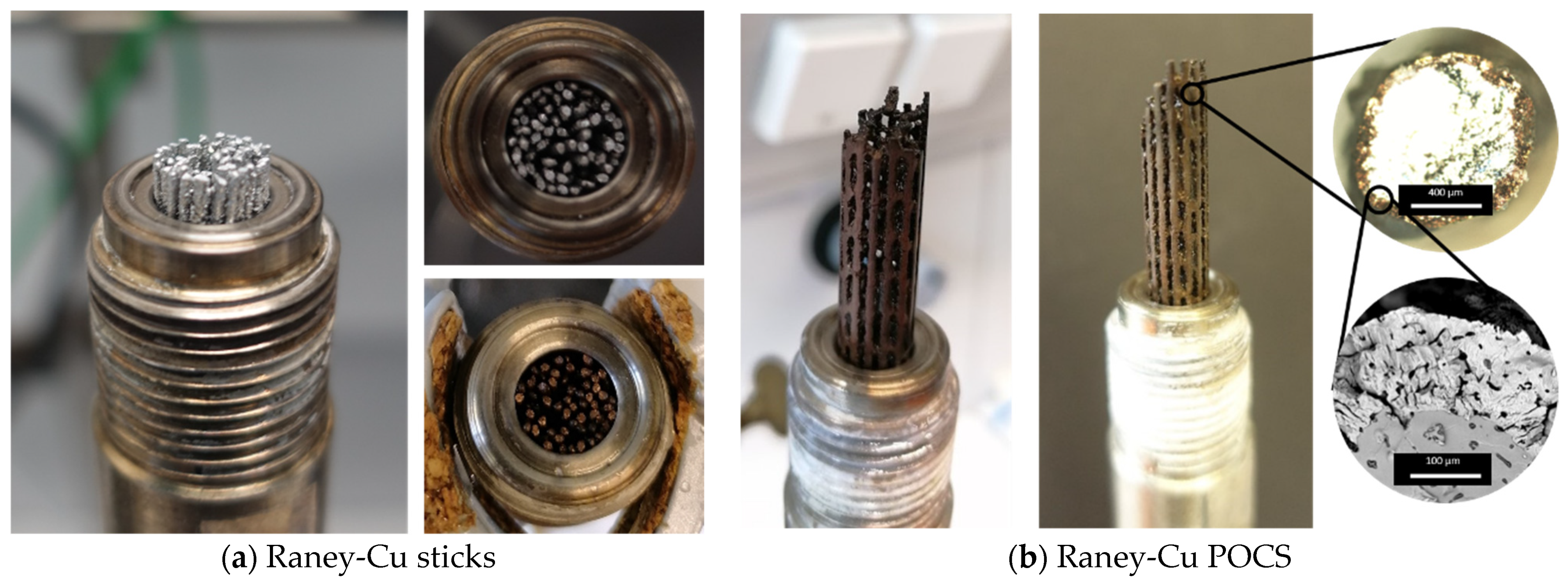
2.1. Fabrication of PBF-EB Sticks and POCS Based on Cu50Al50 Alloy

In order to investigate the influence of the macroscopic structure on the catalytic activity, the Raney-Cu catalysts were manufactured in two different structure variations: sticks (Figure 1a) and POCS (Figure 1b). Both structural variations were fabricated by PBF-EB.
The sticks are solid cylinders with an average diameter of 0.83 ± 0.04 mm and an approximate length of 29 mm. The POCS are structurally based on a diamond unit cell with a node distance of 4 mm. They form open cellular cylinders with a diameter of 10 mm and a length of 50 mm. The individual struts of the POCS are of similar diameter as the sticks. In order to check the inner structure of the POCS, a digital 3D reconstruction based on CT scans was created (Figure 1c).
Since the PBF-EB fabrication of the POCS makes it difficult to control the diameter within tight tolerances, the POCS were mechanically adjusted to fit the slightly smaller reactor (inner diameter 9.7 mm) (Figure 1d).

2.2. Catalytic Activation

To obtain the active Raney-Cu catalyst, the Al was leached from the PBF-EB-fabricated sticks and POCS using an aqueous sodium hydroxide solution. The activated catalyst material was stored under water to avoid oxidation of the highly reactive Raney-Cu surface. In order to maintain the mechanical stability and good thermal conductivity of the sticks and POCS, it proved necessary to preserve a core of the Cu50Al50 alloy. A study of the leaching process provides the necessary information to control the ratio between the active Raney-Cu material (from which the Al has been leached) and the supporting non-porous Cu50Al50 core. Additionally, sodium zincate was added to the leaching solution with the aim of depositing ZnO, which is known to have a promoting effect on the catalytic hydrogenation of CO to methanol [13].
In a kinetic study, the efficiency of the leaching process of Cu50Al50 sticks in a NaOH/Na2Zn(OH)4 solution was investigated by measuring the Al content of the solution (Figure 2). Additionally, the Al content of the remaining solid material was determined at the end of the experiment. The leaching efficiencies determined by both methods are in good agreement.
During the first 0.5 h of the leaching process, no change in the Al concentration was observed. We assume that this is due to the slow dissolution of the oxide layer on the surface of the Cu50Al50 sticks. After this initial phase, a linear increase in the leaching efficiency was observed. This was accompanied by an increase in temperature and the evolution of H2 gas. The comparison between two experiments, with durations of 1 and 2 h, respectively, shows good reproducibility of the leaching process.
A similar study was performed on the fabricated POCS (Figure 3). Again, repeated experiments (2 h at 20 °C, respectively, 3 h at 20 °C) show good reproducibility. The comparison between temperature-controlled experiments at 20 °C and 25 °C shows that leaching occurs faster at higher temperature. Although the leaching efficiency increases linearly at the beginning, the slope decreases at longer reaction times. This is likely due to the limited mass transport between the core of the structure and the solution. Nevertheless, a leaching efficiency of 0.6 was reached after 4.75 h.
For a more detailed investigation of changes in the solid catalyst during the leaching process, Cu50Al50 sticks were leached in NaOH and NaOH/Na2Zn(OH)4 solutions with solid samples taken after defined leaching times. Figure 4 shows the leaching efficiencies (determined by ICP-OES), leaching depths (determined by microscopy), specific surface areas (determined by N2 sorption), and active copper surface areas (determined by N2O decomposition) of those samples.
All of these studies (Figure 4a–d) show, that the leaching process progresses much more rapidly in NaOH solution than in the NaOH/Na2Zn(OH)4 solution. After identical leaching time, the sticks in the NaOH solution achieve higher leaching efficiencies, higher leaching depths, higher specific surface areas, and higher active Cu surface areas. Specifically the leaching efficiency in NaOH/Na2Zn(OH)4 reaches 0.3 after 4 h, whereas in pure NaOH a leaching efficiency of 0.35 is already reached after 2 h. A similar trend can be observed for the leaching depths and surface areas (BET and active Cu surface). The largest difference is observed in the active copper surface area, which is, after 4 h, about seven times higher in the NaOH solution compared to the NaOH/Na2Zn(OH)4 solution.
A likely reason for this behaviour is the deposition of Zn(OH)2 or ZnO on the catalyst surface during the leaching process, which hinders further Al leaching and blocks the active copper centres.
The simultaneous linearity of the increase in leaching efficiencies, leaching depths, and surface areas deviates from the theoretically expected behaviour of a homogeneous material. With increasing depth, less material can be leached from a cylindrical object. Therefore, simultaneous linearity is theoretically not possible. Only the BET surface of the sticks leached in NaOH without Na2Zn(OH)4 shows the expected behaviour, i.e., a slower increasing leaching efficiency during the later stages of the leaching process. A possible explanation for this non-ideal behaviour is that the PBF-EB manufacturing process results in an inhomogeneous catalyst structure.
The microscope images presented in Figure 5, show that the sticks (top row), and to an even greater extend the POCS (lower rows), deviate significantly from the cylindrical shape. In all images, the darker nanoporous Cu is clearly distinguishable from the silvery metallic Cu50Al50 alloy.
The images also clearly visualize the leaching progress over time (Figure 5, row 2 to row 3). The POCS leached for 4.75 h show a much thicker nanoporous Cu layer than the POCS that were only leached for 2 h. In the images of the sticks, the np-Cu layer is fairly uniform, whereas in the POCS slightly more irregularities in the layer thickness appear. This is probably due to the mechanical treatment after the PBF-EB process and the resulting deviation from the cylindrical cross-section (Figure 5 middle row).
The resulting Raney-Cu sticks and POCS were characterized before their use as catalysts in the methanol synthesis process (Table 1). Besides the determination of the aforementioned leaching efficiencies, leaching depths, and active surface areas, this analytical work included elemental analysis of both, the np-Cu layer (by EDX) and the whole structure (by ICP-OES).
The total structure retains a significant amount of Al, even after 4.75 h of leaching, which is contained in its solid core. The np-Cu layer contains very little residual Al but takes up some Zn. Interestingly, the Zn content of the np-Cu layer decreases with longer leaching times (from 28.6 % after 2 h to 13.7 % after 4.75 h). At the same time, the active Cu-surface increases significantly (from 3.0 m2g−1np-Cu after 2 h to 12.2 m2g−1np-Cu after 4.75 h). In comparison, the conventional methanol synthesis catalyst has an active Cu surface of around 9 0 m2g−1np-Cu [20]. The Zn/Cu ratio of the POCS reaches 0.35 after 4.75 of leaching, which is a similar value as in the conventional methanol synthesis catalyst with 0.37 [20]

2.3. Methanol Synthesis in a Fixed-Bed Reactor

The catalytic activity of the PBF-EB-fabricated and leached catalyst structures was tested in the synthesis of methanol from CO hydrogenation. To this end, 60 Raney-Cu sticks, or one POCS respectively, were placed in a tubular methanol synthesis reactor (Figure 6).
The sticks are only connected by their porous Raney-Cu surfaces, whereas the POCS contain a solid Cu50Al50 core. It is therefore expected that the POCS have a much better thermal conductivity than the sticks. Both the sticks and POCS were compared to a commercial methanol synthesis catalyst (Cu/ZnO/Al2O3, Alfa Aesar, LOT Nr. I06Z036) and a Raney-Cu cylinder on which we reported previously [19]. The hydrogenation of CO to methanol was performed at 75 bar and 250 °C with a flow of 300 mLN min−1 of a 2:1 mixture of H2 and CO and a reaction time of 10–12 h. The resulting productivities and selectivities are presented in Figure 7.
The Raney-Cu PBF-EB sticks and POCS achieved significantly higher productivities than the commercially available methanol synthesis catalyst and the previously reported Raney-Cu cylinder. Based on the content of active porous Cu, the PBF-EB sticks reached a productivity of 2.2 gCH3OH gnp-Cu−1 h−1 which is 65 % higher than the commercial Cu/ZnO/Al2O3 benchmark catalyst. Raney-Cu POCS achieved a 46 % higher productivity with 1.9 gCH3OH gnp-Cu−1 h−1.
The selectivity for methanol is slightly lower for the new Raney-Cu catalysts compared to the commercial methanol catalyst. The sticks achieved a selectivity of 80%, the POCS reached a selectivity of 90%. This lower selectivity is due to the formation of dimethylether (DME), which has been observed as a consecutive product of the further dehydration of two methanol molecules according to Equation (5). This has also been observed to a greater extend and reported previously for the LMD cylinders [19].
Overall, the new additively manufactured Raney-Cu sticks and POCS outperformed the previously reported Raney-Cu cylinder [19] and achieved higher productivities with respect to their active Cu content than the commercially available methanol synthesis catalyst. Relative to their total mass, however, the new catalysts perform worse (0.46 gCH3OH gtotal mass−1 h−1 for the sticks) than the commercial catalyst (0.88 gCH3OH gtotal mass−1 h−1), because they contain a catalytically inactive Al50Cu50 core.
The POCS for this test were leached for a duration of 4.75 h. As a result of this intense leaching, the outer struts of the POCS were somewhat fragile and mechanical damage was observed at the end of the experiments. Lowering the leaching time of the POCS improves mechanical stability but increases the Zn/Cu ratio of the catalyst, which influences the catalytic activity. Investigations on the dependence of the catalytic activity on the Zn/Cu ratio are presented in Figure 8. The best POCS, which were leached for 4.75 h, have a Zn/Cu ratio of 0.34. This is similar to the ratio of the commercial methanol synthesis catalyst that has a Zn/Cu ratio of 0.37. Both catalysts performed well in the methanol synthesis reaction. POCS with lower leaching times have much higher Zn/Cu ratios (0.65 after 2 h and 0.56 after 3 h, respectively) and perform significantly worse. A likely explanation for this behaviour is that with the accumulation of ZnO, the passivation of the active Cu surface by the oxide layer overcomes the promoting effect of the ZnO. It appears that, irrespective of the manufacturing process, a lower Zn/Cu ratio provides better results.

2.4. Reaction Engineering Studies

With selected Raney-Cu catalysts, more detailed kinetic studies were carried out. The effective activation energy (EA,eff) was determined from an Arrhenius plot for Raney-Cu sticks and POCS with a leaching time of 2 and 3 h, respectively (see Figure 9).
The plot of the logarithm of the reaction rate (ln(r1)) over the inverse temperature (1/K) shows effective activation energies between 94.2 kJ mol−1 (sticks) and 95.7 kJ mol−1 (POCS). These numbers are in good agreement with previously published values for methanol synthesis using Cu/ZnO catalysts [22,23,24].
To determine the order of reaction with respect to H2, a variation of the H2 partial pressure was carried out, using the Raney-Cu sticks (Figure 10). For these experiments, N2 was added to keep the total pressure as well as the CO partial pressure constant. Figure 10 shows that the methanol productivity correlates linearly with the H2/CO ratio. The effective reaction order with respect to H2 has been determined to 1.02. For conventional co-precipitated Cu/ZnO methanol synthesis catalysts, reaction orders of 1 to 1.5 with respect to hydrogen have been reported [13].
The similarity between our additively manufactured Raney-Cu catalyst and the commercial methanol catalyst regarding reaction order and activation energy indicates that the catalytic mechanism is the same or very similar.
A variation of the volume flow reveals the influence of the residence time on the productivity and selectivity (Figure 11). At low volume flow of 150 mLN min−1, the productivity ranges between 1.1 and 1.2 gCH3OH gnp-Cu−1 h−1, irrespective of the temperature. Increasing the volume flow to 300 mLN min−1 and further to 600 mLN min−1 did not improve the productivity at a process temperature of 260 °C but resulted in a significant increase of the productivity at higher temperatures (from 1.1 gCH3OH gnp-Cu−1 h−1 at 150 mLN min−1 up to 1.8 gCH3OH gnp-Cu−1 h−1 at 600 mLN min−1 and 280 °C).
The generally high selectivity for methanol (0.7 to 0.8) improves marginally with higher volume flows at 260 °C and 270 °C, respectively. However, at 280 °C the selectivity is greatly improved (from 0.7 to 0.8) at higher volume flow. As an interesting consecutive product, DME was observed. The formation of DME is favoured at higher temperatures and higher residence times (i.e., lower volume flows).

3. Materials and Methods

3.1. Synthesis of Periodic Open Cellular Raney-Cu Structures

3.1.1. Selective Electron Beam Melting of the Cu50Al50 Alloy

A detailed description of the fabrication of the Raney-Cu structures has already been published [17] and is only briefly summarized here. For all Cu50Al50 structures, an inert gas atomized pre-alloyed Cu50Al50 powder with a nominal composition of 50 wt% copper, a balance of aluminum (ECKA Granules GmbH, Fürth, Germany), and a particle size distribution between 45 and 105 μm was processed. The PBF-EB system Freemelt ONE (Freemelt AB, Mölndal, Sweden) was used for sample fabrication. The POCS were built based on a diamond unit cell (node distance 4 mm) with a cylindrical diameter of 10 mm and a height of 50 mm. Due to the brittle nature of the alloy, an additional support structure ensured structural integrity of the POCS (see Figure 1b). The PBF-EB process is a powder bed-based process where the structures are built layer by layer. A layer thickness of 100 µm is melted with a line energy of 1.3 J mm−1 and a scan velocity of 0.23 m s−1. The individual struts of the POCS showed a strut thickness of 0.9 ± 0.1 mm and 1.3 ± 0.1 mm, respectively [17].

3.1.2. Catalytic Activation of PBF-EB Sticks and POCS

For catalytic activation of the 3D printed Cu50Al50 sticks and POCS the principal of Raney was used [8]. In the applied leaching process, the aluminum was selectively removed by a sodium hydroxide solution, with the remaining copper forming a nanoporous solid structure according to Equation (1).
2   Al + 2   NaOH + 6   H 2 O 2   Na Al OH 4 + 3 H 2
The preparation of structured Raney-Cu catalysts was carried out in the same manner, except that the leaching reaction was controlled to produce a defined core shell structure. The samples were activated in two different leaching solutions (4.9 M NaOH and 4.9 M NaOH/0.5 M Na2Zn(OH)4) to investigate the effect of sodium zincate on the catalytic properties. The leaching solution was prepared in excess (100 mL) and the Cu50Al50 samples were added (2–4 g). Leaching times between 0.5–5 h were applied to determine the leaching kinetics. After the leaching reaction, the resulting Raney-Cu catalyst was neutralized in deionized water. Due to the pyrophoric properties of Raney-catalysts, the activated catalyst samples were stored under water. To study the leaching kinetics, liquid samples of the leaching solution were taken, and their aluminum content was measured via inductively coupled plasma optical emission spectroscopy (ICP-OES, Plasma 400 from Perkin-Elmer, Waltham, MA, USA).

3.1.3. Catalyst Characterization

The leaching progress is described by the leaching efficiency, which is determined by the remaining aluminum content as calculated via Equation (2).
η l e a c h i n g = m A l i n m A l o u t m A l i n
The leaching efficiency η l e a c h i n g can be determined by balancing the aluminum content in the leaching solution or by measuring the content of the resulting Raney-Cu catalyst. The aluminum content was measured via inductively coupled plasma optical emission spectroscopy (ICP-OES, Plasma 400 from Perkin-Elmer, Waltham, USA for details see Supporting information). The leaching depth of the catalyst materials was determined by using a Nikon Eclipse 50i light microscope. For this purpose, the structured Raney-Cu catalyst was broken vertically and glued onto a sample holder. The specific surface area was calculated with the Brunnauer-Emmet-Teller (BET) method from N2-physisorption at a temperature of 77 K. The sorption measurements were performed using a Quadrasorb SI from Quantachrome Instruments, Boynton Beach, FL, USA. The active copper surface area of the catalysts was measured by decomposition of nitrous oxide using an isothermal flow experiment in an Autochem II 2920 from Micromeritics, Norcross, USA (see Supporting information, Figures S1–S3).

3.2. Catalytic Activity for Methanol Synthesis

3.2.1. Test-Setup and Experimental Procedure

Catalytic hydrogenation experiments of CO to methanol were carried out in a continuous fixed-bed reactor. The simplified flowsheet is shown in Figure 12. The gas volume flows were adjusted with mass flow controllers (Bronkhorst, Kamen Germany). After passing the static mixer and the heated pipe (150 °C), the gas reached the reactor inlet. A stainless-steel tubular reactor was used (length L = 45 mm, inner diameter d = 9.7 mm) equipped with a thermocouple at the end of the catalyst bed. The reactor was heated with a heating jacket to a maximal temperature of 300 °C. The pressure in the reactor was adjusted with a back-pressure regulator (BPR-3.1). Behind BPR-3.1 the gas was depressurised to atmospheric pressure. A part of the gas was sent over a heated capillary (T = 150 °C) to the online GC (Agilent 7820, Waldbronn, Germany). Prior to the catalytic testing, the catalyst was dried in 100 mLN min−1 N2 at atmospheric pressure. After 1 h of drying at 80 °C the catalyst was heated in 5 K/min to 250 °C. Subsequently, a reduction in 100 mLN min−1 H2 was performed for one hour at atmospheric pressure. The reaction was conducted at 75 bar and 250 °C with a total volume flow of 300 mLN min−1. The molar ratio of the reactants H2/CO was set to 2. The product gas was analysed with online gas chromatography (Agilent 7820) equipped with two columns (Plot U, Molsieve) and two thermal conductivity sensors. To terminate the experiment, the reactor pressure was slowly reduced to atmospheric pressure and cooled down to 100 °C under a 100 mLN min−1 N2 stream. The tested catalysts were passivated at 100 °C with 100 mLN min−1 in 1 vol.% N2O in He for 1 h.

3.2.2. Data Evaluation

For data evaluation, balancing of the inlet and outlet streams of the laboratory test-rig was necessary. In the following equations the index 0 stands for the inlet, whereas the index 1 stands for the outlet conditions. The inlet mole flow n ˙ i , 0 of the different components was determined using the ideal gas law and was set up by the mass-flow controllers as shown in Equation (3).
n ˙ i , 0 = p V ˙ i , 0 R T
For calculating the outlet mole flow the following reaction Equations (4)(6) were taken into account.
r 1 :   CO + 2   H 2 CH 3 OH
r 2 : 2   CH 3 OH H 3 C O CH 3 + H 2 O
r 3 : CO + H 2 O CO 2 + H 2
With the following Equations (7)(9), the different extents of reactions were calculated under minimization of the least square sum of the measured GC values y i , 1 G C and the calculated outlet mole fractions y i , 1 c a l c . With the indices i for the different components and j for the different reactions, the following equations could be solved:
m i n r j y i , 1 G C y i , 1 c a l c 2
y i , 1 c a l c = n i , 0 + j ν i , j r j k ( n k , 0 + j ν k , j r j )
n g e s , 1 = k ( n k , 0 + j ν k , j r j )
With n g e s , 1 it is possible to calculate the typical reaction engineering parameters conversion Xi and selectivity Si,l (Equations (10) and (11)).
X i = n ˙ i , 0 n ˙ i , 1 n ˙ i , 0
S i , l = n ˙ i , 1 n ˙ i , 0 n ˙ l , 0 n ˙ l , 1 ν l ν i
The synthesized catalysts were compared with respect to their methanol productivity. The methanol productivity is often related to the mass of the catalyst, as this is the easiest accessible value for comparison (see Equation (12)).
P C H 3 O H m c a t = m ˙ C H 3 O H m c a t
Since typically not all parts of the catalyst are catalytically active, the productivity based on the mass of nanoporous Cu (mnp-Cu) was used alternatively (Equation (13)). Thereby, the mnp-Cu was determined from the leaching process: since an alloy of 50 wt.% Cu and 50 wt.% Al was used, it follows that the mass of nanoporous Cu after the leaching process equals the mass of leached Al (Equation (14)), which was measured by ICP-OES.
P C H 3 O H m n p C u = m ˙ C H 3 O H m n p C u
m n p C u = m A l

4. Conclusions

In summary, we have shown that 3D printed Raney-Cu materials that have been catalytically activated by leaching in an aqueous sodium zincate solution, are promising catalyst materials for the synthesis of methanol. They can be manufactured additively by PBF-EB processing using a commercially available Cu50Al50 alloy. The same process allows the production of POCS. The active methanol synthesis catalyst can be obtained from the printed alloy structure by leaching the Al using an aqueous solution of NaOH/Na2Zn(OH)4.
We have tested the catalytic performance of the so-obtained catalyst materials under industrially relevant conditions (250 °C, 75 bar, Vges = 300 mLN min−1, pH2/pCO = 2) and demonstrated that their productivity and selectivity is comparable to the state-of-the-art co-precipitated methanol synthesis catalyst. Productivities up to 2.2 gCH3OH gnp-Cu−1 h−1 at 600 mLN min−1 and 280 °C have been found. Thus, our results indicate that additively manufactured catalyst structures can offer new and very interesting perspectives for methanol synthesis and other highly exothermic hydrogenation reactions using continuous gas phase processes in fixed-bed reactors.

Supplementary Materials

The following supporting information can be downloaded at: https://www.mdpi.com/article/10.3390/catal12101288/s1, Figure S1: Nitrous oxide flow experiment; Figure S2: Schematic flowsheet of the Autochem 2920; Figure S3: Active copper surface area of the tested catalyst before (fresh) and after methanol synthesis (used) for the tested catalysts.

Author Contributions

Conceptualization, J.A., C.K. and P.W.; methodology, C.R. and T.W.; validation, M.J.P. and C.R.; writing—original draft preparation, M.J.P. and C.R.; writing—review and editing, C.K., P.W. and J.A.; visualization, C.R. All authors have read and agreed to the published version of the manuscript.

Funding

Financial support from the Deutsche Forschungsgemeinschaft (DFG LO 2030/1-1, WA 1615/15-1, and INST 90/1043-1 FUGG) is gratefully acknowledged.

Data Availability Statement

Not applicable.

Conflicts of Interest

The authors declare no conflict of interest. The funders had no role in the design of the study; in the collection, analyses, or interpretation of data; in the writing of the manuscript; or in the decision to publish the results.

References

  1. Narkhede, N.; Singh, S.; Patel, A. Recent Progress on Supported Polyoxometalates for Biodiesel Synthesis via Esterification and Transesterification. Green Chem. 2015, 17, 89–107. [Google Scholar] [CrossRef]
  2. Kumar, A.; Daw, P.; Milstein, D. Homogeneous Catalysis for Sustainable Energy: Hydrogen and Methanol Economies, Fuels from Biomass, and Related Topics. Chem. Rev. 2022, 122, 385–441. [Google Scholar] [CrossRef] [PubMed]
  3. Park, C.W.; Williams, B.P.; Kelly, G.J.; Fitzpatrick, T.J. Methanol Synthesis Process. WO 2010/146380, 17 June 2009. [Google Scholar]
  4. Kung, H.H. Deactivation of Methanol Synthesis Catalysts—A Review. Catal. Today 1992, 11, 443–453. [Google Scholar] [CrossRef]
  5. Castoldi, M.C.M.; Câmara, L.D.T.; Aranda, D.A.G. Kinetic Modeling of Sucrose Hydrogenation in the Production of Sorbitol and Mannitol with Ruthenium and Nickel-Raney Catalysts. React. Kinet. Catal. Lett. 2009, 98, 83–89. [Google Scholar] [CrossRef]
  6. Wolf, A.; Turek, T.; Mleczko, L. Structured Raney Nickel Catalysts for Liquid-Phase Hydrogenation. Chem. Eng. Technol. 2016, 39, 1933–1938. [Google Scholar] [CrossRef]
  7. Wainwright, M.S.; Trimm, D.L. Methanol Synthesis and Water-Gas Shift Reactions on Raney Copper Catalysts. Catal. Today 1995, 23, 29–42. [Google Scholar] [CrossRef]
  8. Raney, M. Catalysts from Alloys. Ind. Eng. Chem. 1940, 32, 1199–1203. [Google Scholar] [CrossRef]
  9. Spencer, M.S.; Twigg, M.V. Metal Catalyst Design and Preparation In Control of Deactivation. Annu. Rev. Mater. Res. 2005, 35, 427–464. [Google Scholar] [CrossRef]
  10. Smith, A.J.; Wainwright, M.S. Skeletal Metal Catalysts. In Handbook of Heterogeneous Catalysis; Wiley-VCH Verlag GmbH & Co. KGaA: Weinheim, Germany, 2008. [Google Scholar] [CrossRef]
  11. Ostgard, D.; Moebus, K.; Berweiler, M.; Bender, B.; Stein, G. Fixed Bed Catalysts. US 2002/0037808, 25 August 2002. [Google Scholar]
  12. Schuetz, P.; Burmeister, R.; Despeyroux, B.; Moesinger, H.; Krause, H.; Deller, K. Catalyst Precursor for an Activated Raney Metal Fixed-Bed Catalyst, an Activated Raney Metal Fixed-Bed Catalyst and a Process for Its Preparation and Use, and a Method of Hydrogenating Organic Compounds Using Said Catalyst. US 5,536,694, 16 July 1996. [Google Scholar]
  13. Hansen, J.B.; Hojlund Nielsen, P.E. Methanol Synthesis. In Handbook of Heterogeneous Catalysis; Wiley-VCH Verlag GmbH & Co. KGaA: Weinheim, Germany, 2008; Volume 2, pp. 2920–2949. [Google Scholar] [CrossRef]
  14. Stephan, P.; Kabelac, S.; Kind, M.; Mewes, D.; Schaber, K.; Wetzel, T. VDI-Wärmeatlas, 11th ed.; Springer: Berlin/Heidelberg, Germany, 2013. [Google Scholar] [CrossRef]
  15. Klumpp, M.; Inayat, A.; Schwerdtfeger, J.; Körner, C.; Singer, R.F.; Freund, H.; Schwieger, W. Periodic Open Cellular Structures with Ideal Cubic Cell Geometry: Effect of Porosity and Cell Orientation on Pressure Drop Behavior. Chem. Eng. J. 2014, 242, 364–378. [Google Scholar] [CrossRef]
  16. Busse, C.; Freund, H.; Schwieger, W. Intensification of Heat Transfer in Catalytic Reactors by Additively Manufactured Periodic Open Cellular Structures (POCS). Chem. Eng. Process. Process Intensif. 2018, 124, 199–214. [Google Scholar] [CrossRef]
  17. Wolf, T.; Fu, Z.; Ye, J.; Heßelmann, C.; Pistor, J.; Albert, J.; Wasserscheid, P.; Körner, C. Periodic Open Cellular Raney-Copper Catalysts Fabricated via Selective Electron Beam Melting. Adv. Eng. Mater. 2020, 22, 1901524. [Google Scholar] [CrossRef] [Green Version]
  18. Montebelli, A.; Visconti, C.G.; Groppi, G.; Tronconi, E.; Ferreira, C.; Kohler, S. Enabling Small-Scale Methanol Synthesis Reactors through the Adoption of Highly Conductive Structured Catalysts. Catal. Today 2013, 215, 176–185. [Google Scholar] [CrossRef]
  19. Heßelmann, C.; Wolf, T.; Galgon, F.; Körner, C.; Albert, J.; Wasserscheid, P. Additively Manufactured RANEY®-Type Copper Catalyst for Methanol Synthesis. Catal. Sci. Technol. 2020, 10, 164–168. [Google Scholar] [CrossRef]
  20. AlfaAesar. 45776 Copper Based Methanol Synthesis Catalyst. Available online: https://www.alfa.com/de/catalog/045776/ (accessed on 12 September 2022).
  21. Renz, C. Strukturierte Raney-Cu-Katalysatoren für den Einsatz in der Methanolsynthese. Ph.D Thesis, FAU Erlangen-Nürnberg, Erlangen, Germany, October 2022. [Google Scholar]
  22. Chanchlani, K. Methanol Synthesis from H2, CO, and C02 over Cu/ZnO Catalysts. J. Catal. 1992, 136, 59–75. [Google Scholar] [CrossRef]
  23. Dadgar, F.; Myrstad, R.; Pfeifer, P.; Holmen, A.; Venvik, H.J. Direct Dimethyl Ether Synthesis from Synthesis Gas: The Influence of Methanol Dehydration on Methanol Synthesis Reaction. Catal. Today 2016, 270, 76–84. [Google Scholar] [CrossRef] [Green Version]
  24. Lewis, W.K.; Frolich, P.K. Synthesis of Methanol from Carbon Monoxide and Hydrogen 1. Ind. Eng. Chem. 1928, 20, 285–290. [Google Scholar] [CrossRef]
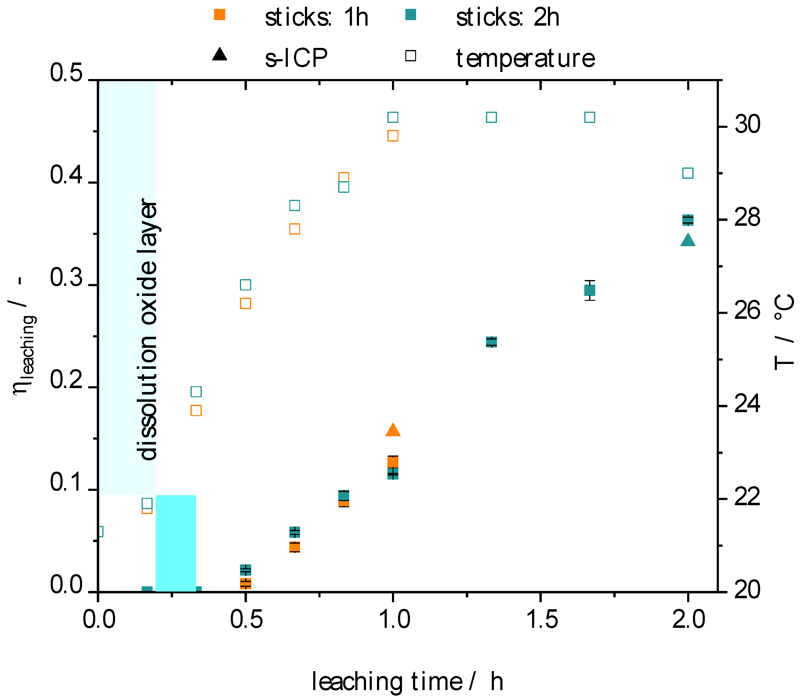
Figure 1. Representation of the investigated sticks and POCS based on Cu50Al50 alloy: (a) PBF-EB sticks; (b) POCS structures on starter plate in the PBF-EB process; (c) section of a CT reconstruction of a POCS; and (d) as-built structure (left) and mechanically post-processed POCS to methanol reactor dimension (right), adapted from [17].
Catalysts 12 01288 g001
Figure 2. Kinetic of the leaching reaction of PBF-EB Cu50Al50 sticks for different leaching times, filled squares Catalysts 12 01288 i001 denote η l e a c h i n g determined by ICP-OES of liquid samples of leaching solution (left axis), filled triangles Catalysts 12 01288 i002 denote η l e a c h i n g determined by ICP-OES of solid sample after leaching reaction (also left axis), ( η l e a c h i n g = 1 → all Aluminum is leached out), empty squares denote the temperature observed during the leaching process (right axis); leaching conditions: room temperature, 100 mL 4.9 M NaOH/0.5 M Na2Zn(OH)4, msticks = 4 g.
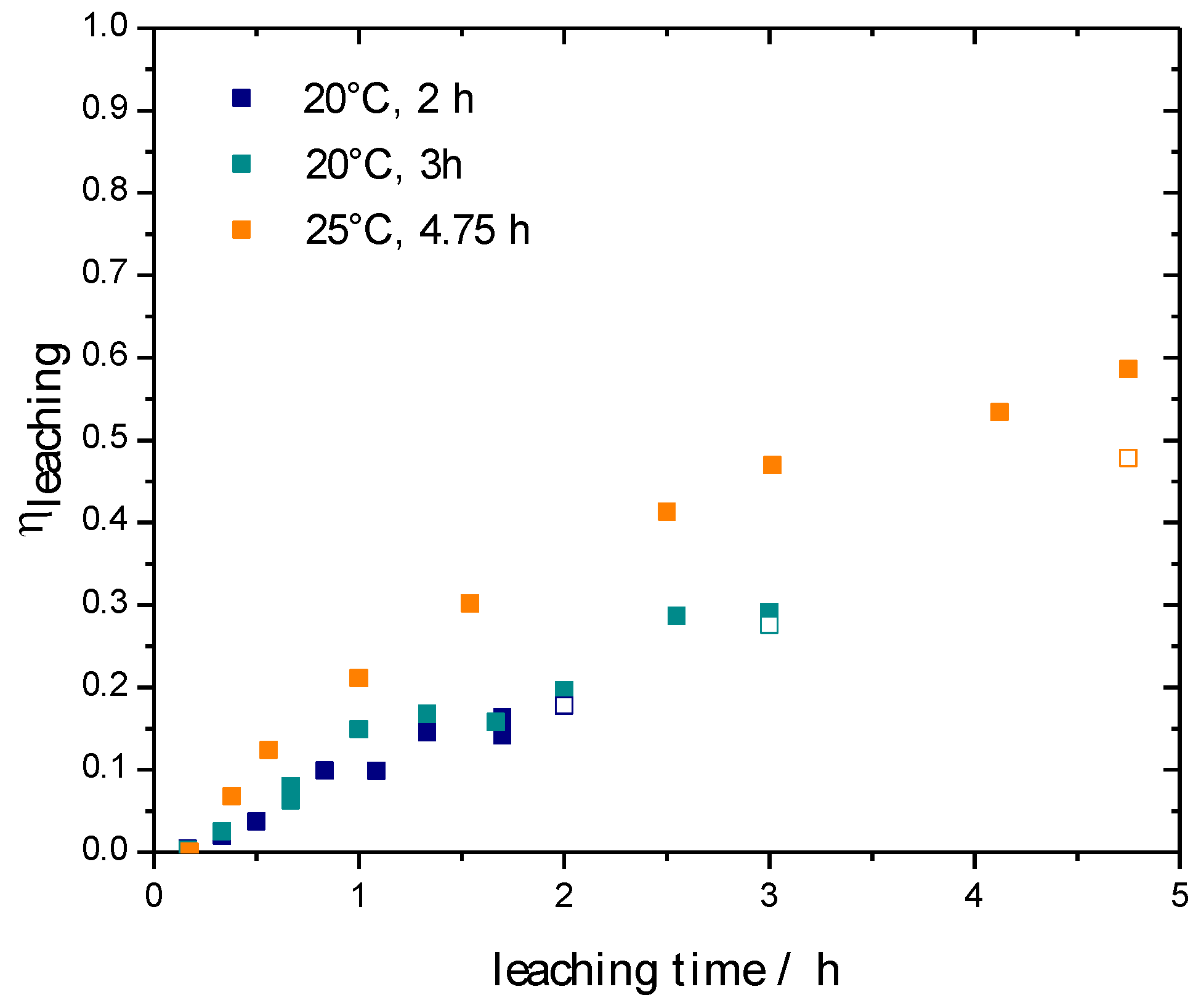
Catalysts 12 01288 g002
Figure 3. Kinetic of the leaching reaction of PBF-EB Cu50Al50 POCS at controlled leaching temperature, Catalysts 12 01288 i001: η l e a c h i n g determined by ICP-OES of liquid samples of leaching solution, ☐: η l e a c h i n g determined by ICP-OES of solid sample after leaching reaction, ( η l e a c h i n g = 1 → all Aluminum is leached out), leaching conditions: 20 or 25 °C, 100 mL 4.9 M NaOH/0.5 M Na2Zn(OH)4, mPOCS = 2.7–4.4 g.
Catalysts 12 01288 g003
Figure 4. Kinetic Leaching study of the PBF-EB Cu50Al50 sticks in 4.9 M NaOH (Catalysts 12 01288 i003
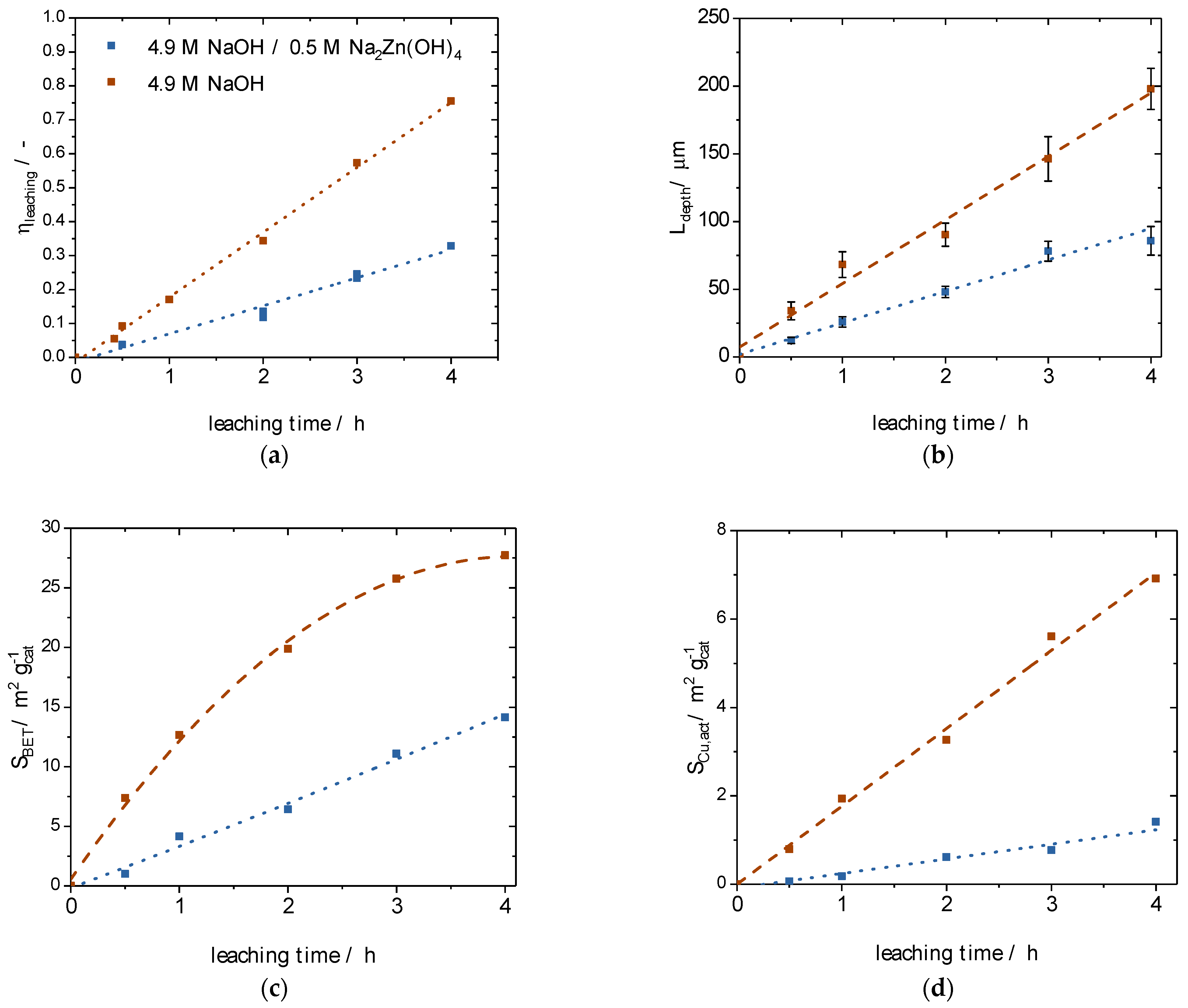
) and 4.9 M NaOH/0.5 M Na2Zn(OH)4 (Catalysts 12 01288 i004) for different leaching times: (a) leaching effectiveness factors; (b) leaching depths; (c) specific surface areas; and (d) active copper surface areas.
Catalysts 12 01288 g004
Figure 5. Microscope images of different cross-sections of the Raney-Cu PBF-EB sticks (top row) and of individual struts of the Raney-Cu POCS (lower rows).
Catalysts 12 01288 g005
Figure 6. Arrangement of tested Raney-type catalyst in our methanol synthesis reactor: (a) parallel arrangement of 60 Cu50Al50 PBF-EB sticks [left] and [right] plan-view of 60 synthesized [right-top] activated [right-bottom] Raney-Cu sticks ( V b e d = 2.14   mL ,   ε b e d = 0.6 ) ; and (b) activated Raney-Cu POCS for methanol synthesis [left] and passivated Raney-Cu POCS after methanol synthesis with microscopic view of strut cross section [right-top] and SEM-Image of nanoporous Raney-Cu layer and Cu50Al50 core [right-bottom] ( V b e d = 2.4 3   mL ,   ε b e d = 0.7 ) .
Catalysts 12 01288 g006
Figure 7. Catalytic activities (productivity in light grey on the left axis; selectivity in dark grey on the right axis) for the additively manufactured Raney-Cu catalysts (s. [21]) in comparison with a commercial Cu/ZnO/Al2O3 catalyst from Alfa Aesar and an earlier published [19] additively manufactured Raney-Cu cylinder (Cu50Al50-base) synthesized in the Laser-Melting-Deposition process (reaction conditions: 75 bar, 250 °C, CO/H2 = 1/2, τBed = 4–10 s).
Catalysts 12 01288 g007
Figure 8. Methanol productivities based on the nanoporous copper mass (PCH3OH(mnp-Cu)) for the tested Raney-Cu POCS in comparison to the commercial Cu/ZnO/Al2O3 catalyst from Alfa Aesar; depending on the given leaching time the Zn/Cu ratio in the active material varies (reaction conditions: 75 bar, 250 °C, CO/H2 = 1/2, TOS = 3–5 h).
Catalysts 12 01288 g008
Figure 9. Arrhenius plot for a temperature variation 200–280 °C for determination of the effective activation energy for the Raney-Cu sticks and Raney-Cu POCS with 2 and 3 h leaching time (reaction conditions: 75 bar, Vges = 300 mLN min−1, 200–280 °C, CO/H2 = 1/2).
Catalysts 12 01288 g009
Figure 10. Influence of H2 partial pressure on methanol productivity for the Raney-Cu sticks (reaction conditions: 75 bar, 250 °C, Vges = 300 mLN min−1, yCO = 1/6 = const, yH2 = 1/6, 1/3,1/2, 2/3, yN2 = 1-yCO-yH2, mcat = 3 g).
Catalysts 12 01288 g010
Figure 11. Influence of the total volume flow on the conversion of CO and on the methanol productivity (a); and on methanol selectivity (b) for the investigated Raney-Cu sticks at different reaction temperatures (reaction conditions: 75 bar, 250 °C, pH2/pCO = 2, mcat = 3 g).
Catalysts 12 01288 g011
Figure 12. Flowsheet of the laboratory rig used in our CO hydrogenation experiments.
Catalysts 12 01288 g012
Table 1. Characterization of the prepared, additively manufactured Raney-Cu sticks and POCS as tested in the CO hydrogenation to methanol.
TimeTleaching CompositionZn/Cu a η s I C P L d e p t h  cSCu,act d
[h][°C] [wt.-%][-][-][-] [ m 2 g c a t 1 ] [ m 2 g n p C u 1 ]
CuAlZn
Raney-Cu sticks
220–30total a56.336.67.1 0.3591 ± 113.116.0
np-layer b---0.38
Raney-Cu POCS
220total51.142.26.0 0.1851 ± 90.33.0
np-layer63.4828.60.65
320total53.238.68.2 0.2873 ± 60.74.6
np-layer68.76.025.30.56
4.7525total59.230.99.9 0.48153 ± 233.512.2
np-layer78.77.613.70.35
a according to ICP-OES; b according EDX measurements; c determined by microscope cross sections; d as determined by N2O decomposition.
Publisher’s Note: MDPI stays neutral with regard to jurisdictional claims in published maps and institutional affiliations.

