1. Introduction
Syngas is a gaseous mixture, mainly composed of hydrogen and carbon monoxide and by small amounts of carbon dioxide and water. The H
2/CO mixture can be produced by gasification of coal/heavy hydrocarbons/biomass and by steam reforming of light hydrocarbons. Syngas is one of the most important intermediates in the chemical industry, mainly used for ammonia, methanol and hydrogen production but also for heat and electricity generation [
1,
2,
3]. Due to the concerns about global warming and the need to switch to renewable fuels and chemicals, the use of biomass for syngas production is deeply studied. During gasification, biomass is converted into syngas in the presence of an oxidizer (air or oxygen) and a gasifying agent, usually water vapor. The process is composed of four steps: drying, pyrolysis, oxidation and reduction [
2]. During the pyrolysis step, occurring at temperatures between 300 and 700 °C, the biomass is decomposed, producing char, gas and vapors, which compose the tar. Part of the produced tar exits from the gasification reactor along with the syngas and can condense in the downstream equipment of the plant, causing clogging of pipes and filters. When the amount of tar exiting from the gasifier is not negligible, for example, when up-draft gasifiers are used, the recovery of the energy of tar by means of its transformation into syngas is fundamental. Tar is a complex mixture of condensable organics, which are generally assumed to be largely aromatic organic species [
3,
4]. Typically, one- or two-ring aromatic hydrocarbons, including benzene, guaiacol, toluene and naphthalene, are chosen as tar model compounds to deeply investigate the performance of the several tar removal methods [
5,
6]. The traditional chemical methods for tar removal are thermal cracking and catalytic reforming; thermal cracking converts tar into syngas and coke at high temperature (T > 800 °C) in the absence of a catalyst; catalytic reforming takes place in the presence of a catalyst, usually Ni, and tar is converted mainly into syngas. These two methods suffer from low conversion efficiency and rapid catalyst deactivation [
7].
In this context, chemical looping technologies can represent a viable alternative to remove tar from the syngas and enrich it with H
2. Among them, chemical looping gasification (CLG) and chemical looping reforming (CLR) have attracted a lot of attention from researchers to improve the efficiency and solve the issues related to tar production [
8,
9,
10]. The process consists of exploiting the redox properties of transition metal oxides in redox cycles. In the first step of the redox cycle, the lattice oxygen of the metal is able to partially oxidizes biomass or tar to syngas, converting the metal oxide into its metallic state. The second step is dedicated to the restoration of the metal oxide using air oxidation to begin the cycle again [
11,
12]. Huang et al. utilized NiFe
2O
4 as oxygen carrier to remove toluene as tar model compound from syngas. The tests showed a high toluene conversion (95%) at 850 °C and also a high stability of the material, which guaranteed a stable conversion after 82 cycles. They also reported the production of a syngas with high H
2 yields [
13]. Zeng et al. studied the conversion of naphthalene as tar model compounds over different metal oxides, showing that at 900 °C, more than 90% of naphthalene is converted into CO, CO
2, H
2 and char when CuO, NiO and Fe
2O
3 are used as oxygen carriers [
14]. The concept of chemical looping hydrogen (CLH) is slightly different, the first step in tar oxidation/reduction of the metal oxides is comparable to that of chemical looping gasification, but the second step, in which the metal oxide is restored, utilizes water vapor instead of air as the oxidation agent with the goal of pure H
2 production. CLH is widely studied for the production of pure H
2 from renewable sources; however, its application in gasification technology is limited [
15]. The most investigated reduction species, needed for the first step of the process, are methane, syngas and ethanol [
16,
17]. When hydrogen with high purity is required, the use of heavy organic reductants in the CLH process is not common since heavy molecules tend to undergo cracking reactions, forming carbon, which is deposited on the oxygen carrier; the carbon, in the subsequent steps of oxidation, can react with the steam to form CO, undermining the purity of the H
2 stream. To overcome the issues related to carbon formation when heavy-molecular-weight reductants are used, some authors proposed the insertion of a third step of air combustion with the aim of burning the carbon deposited and completely restoring the oxides. Wei et al. investigated the production of H
2 using vegetable oils as reductants and Fe
2O
3 as oxygen carrier. The H
2 stream obtained was composed of H
2 at 90% using a three-step CLH [
18]. Xiao et al. also studied a CLH process using bio-oil as reductant and an iron-based oxygen carrier; they worked at 950 °C and obtained an H
2 stream but not pure due to the carbon deposition in the reduction step [
19].
The aim of this work is to demonstrate the feasibility of coupling biomass gasification to CLH technology in order to remove tar from the syngas and to produce, at the same time, a pure H
2 stream. The goal is to enhance the whole process efficiency by converting the tar into pure hydrogen, which can be used to enrich the syngas or, as it is, in other applications. With this process, it will be possible to easily produce H
2 from biomass without the need of separation processes of H
2 from syngas. One of the most interesting destinations of pure H
2 is in fuel cell applications, where the CO concentration should be lower than 10 ppm [
20].
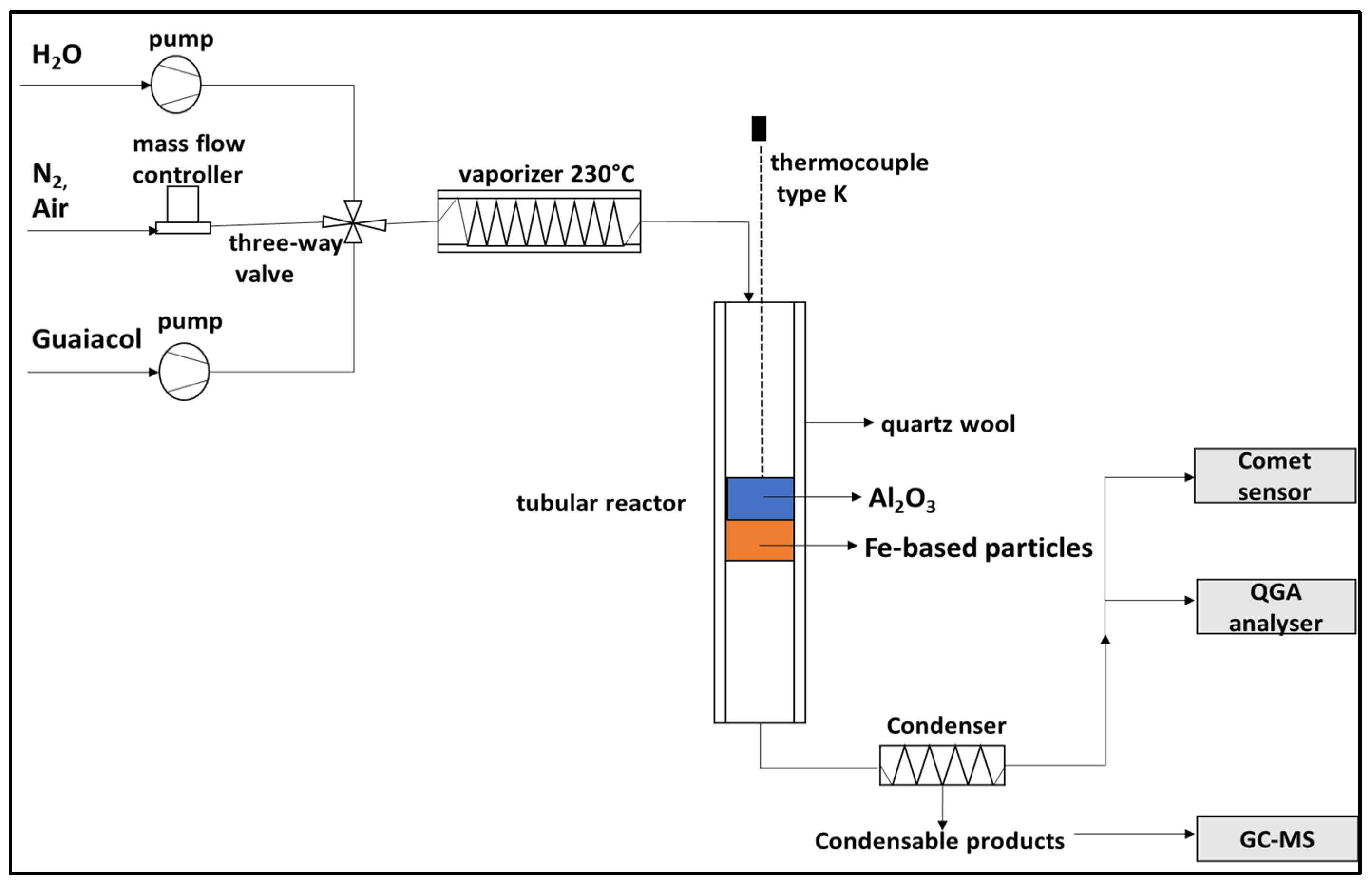
The experimental study reported in this work is focused only on the tar removal system that consists of one reactor with a double-layer fixed bed, working in three different process steps (tar adsorption, tar partial oxidation and pure hydrogen production). The double layer in each reactor is composed of NiO/Al
2O
3 needed to adsorb the tar and to catalyze tar partial oxidation and by Fe-based particles (60 wt% Fe
2O
3/40 wt% MgO), which constitute the CLH redox system [
21]. The catalytic activity of Ni in its oxidized form is proven by numerous studies [
22,
23]. The process consists of three steps: First, guaiacol, used as a tar model compound, is adsorbed mainly on the NiO/Al
2O
3 layer at low temperature (300 °C). In the second step, the adsorbed tar is partially oxidized at 700 °C by air, producing heat and syngas. This step is fundamental to convert the adsorbed guaiacol into CO and H
2 needed to reduce iron oxides to iron and to provide the heat needed for iron oxide reduction reactions, favored at high temperature (700–900 °C). In the third step, steam is fed to the reactor in order to produce pure H
2 by iron oxidation and to restore iron oxide. The experimental tests were conducted, studying separately the three steps, looking at the guaiacol abatement efficiency, purity and amount of the produced hydrogen and stability of the oxygen carrier (60 wt% Fe
2O
3-40 wt% MgO).
3. Discussion
3.1. Characterization of the NiO/Al2O3 and Fe-Based Particles
The synthesized materials were characterized to determine their crystallinity and surface area using XRD and BET, respectively.
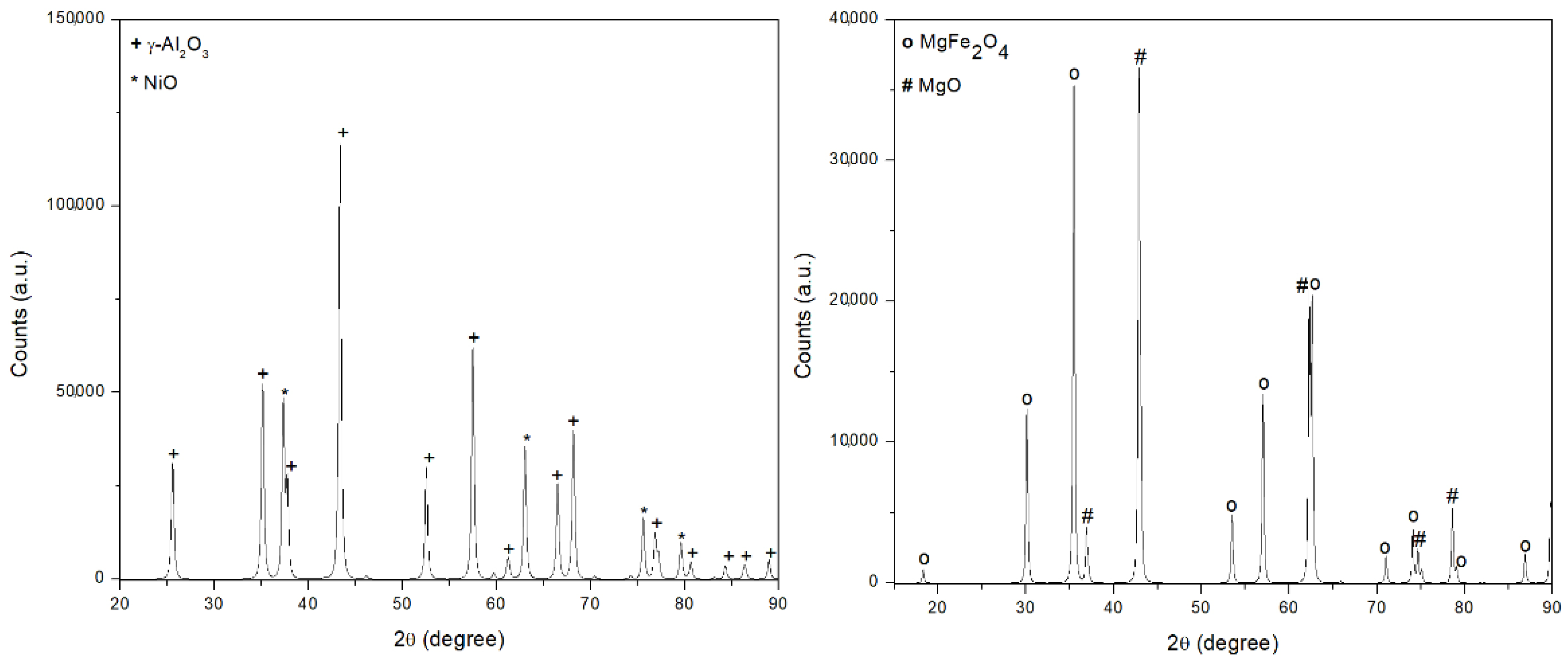
As shown in
Figure 2, the main crystal structures detected in the NiO/Al
2O
3 catalyst are bunsenite (NiO) and corundum (γ-Al
2O
3). No signals associated with the nickel aluminate (NiAl
2O
4) spinel phase were detected, which suggests no solid solution among γ-Al
2O
3 and NiO.
The strong interaction between Fe
2O
3 and MgO is instead detected in the case of the 60 wt% Fe
2O
3/40 wt% MgO sample; after calcination in air at 900 °C, magnesium oxide and iron oxide form a spinel structure magnesium ferrite (MgFe
2O
4). The specific surface areas (BET) together with pore width and pore volume are presented in
Table 1. The NiO/Al
2O
3 catalyst showed a relatively high surface area (196.63 m
2·g
−1), but a slight reduction compared with that of the γ-Al
2O
3 support (212 m
2·g
−1) occurred, probably due to the presence of NiO particles that partially block the porous network of the support. On the contrary, the Fe-based sample presented lower surface area (9.67 m
2·g
−1) and a very low porosity (0.04 cm
3·g
−1) compared to the NiO/Al
2O
3 catalyst (0.40 cm
3·g
−1).
3.2. Low-Temperature Guaiacol Adsorption on NiO/Al2O3 Particles
In order to evaluate the feasibility to use NiO/Al2O3 for the guaiacol adsorption at the operative conditions adopted, tests feeding different amounts of guaiacol (1.365 mmol, 2.731 mmol, 4.095 mmol) are conducted. The flow rate of guaiacol was kept constant at 0.01 mL·min−1 and, thus, to feed the different amounts, only the feeding time was changed from 15 to 45 min. The experiments are performed with only the NiO/Al2O3 layer in order to better understand the behavior of this material in the process.
At these operative conditions, guaiacol does not undergo any type of decomposition reaction [
27]. Therefore, the adsorption efficiency is calculated according to Equation (1):
where
guaiacol liquid product corresponds to the amount of guaiacol collected by condensation at the reactor exit.
Table 2 reports the abatement efficiency calculated for each amount of guaiacol fed.
As reported in
Table 2, guaiacol can be successfully absorbed on NiO/Al
2O
3 at a temperature of 300 °C; however, the time of the adsorption should be carefully tuned and it is a function of the amount of tar into the syngas. The amount of guaiacol in the condensed product at the end of the reactor starts to appear, feeding an amount of guaiacol higher than 2.731 mmol, which corresponds to a feeding time equal to 30 min. For higher feeding time, the abatement efficiency significantly decreases, meaning that the guaiacol is not adsorbed anymore and it is entirely collected as a condensable product. Therefore, the maximum amount of guaiacol that can be adsorbed by the NiO/Al
2O
3 layer is 2.731 mmol.
In order to evaluate if the Fe-based particle layer is involved in the guaiacol adsorption, adsorption experiments are also conducted in the two-layer fixed-bed configuration at the same operative conditions.
Table 3 summarizes the results obtained.
From the comparison of the results obtained with and without the Fe-based particle layer, it seems that only a slight improvement in the guaiacol abatement efficiency is obtained in the layer of Fe-based particles. These results suggest that the Fe-based particles have a little capacity for adsorption; in fact, only a small amount of the guaiacol fed can be adsorbed on the Fe-based particle layer. From the results, the abatement efficiency of the Fe-based particles is almost negligible due to the very low surface area of this material (9.67 m2·g−1) compared to that of NiO/Al2O3 (195.63 m2·g−1).
The adsorption of guaiacol into the Fe-based particles is a key aspect that needs to be carefully addressed; in fact, when the temperatures increase during the reduction step, the amount of guaiacol adsorbed onto the Fe-based particles could undergo cracking reactions and form solid carbon on the Fe-based particles, causing deactivation of the active sites. Furthermore, the carbon can react with water vapor in the oxidation steps, producing CO via the gasification reaction. From these considerations, it is clear that the adsorption of guaiacol into the Fe-based particles must be avoided and for the reduction/oxidation tests, the amount of guaiacol that does not imply its adsorption also in the Fe layer is taken as the optimum amount. The tests of reduction/oxidation were, thus, performed feeding guaiacol for 30 min.
3.3. Guaiacol Partial Oxidation
After the determination of the maximum amount of guaiacol adsorbed by NiO/Al
2O
3 layer, guaiacol partial oxidation experiments are conducted in order to verify the feasibility to partially oxidize guaiacol to form mainly H
2, CO and CO
2. The resulting syngas mixture is used to reduce iron oxides to iron. The experiments are conducted using the configuration in which only the NiO/Al
2O
3 layer is present in order to separately study the partial oxidation of guaiacol and the iron oxide reduction, to measure the amount of heat supplied to the fixed bed by the exothermic partial oxidation reactions [
28]. The amount of air fed should be carefully calculated in order to avoid the complete combustion of the adsorbed guaiacol, resulting in the production of CO
2 and H
2O, which could not contribute to iron oxide reduction. Furthermore, oxygen needed for the combustion must be totally consumed by the guaiacol oxidation rection, as its presence at the end of the Al
2O
3 layer hinders the iron oxide reduction. Before starting the partial oxidation step, the reactor is preheated to 700 °C.
The required air flow rate is calculated starting from the maximum amount of guaiacol that can be adsorbed on the NiO/Al
2O
3 layers determined in the previous process step. According to the stoichiometry of guaiacol combustion reaction (reaction (2)), the amount of air required to obtain a complete guaiacol oxidation in 30 min is equal to 80 mL·min
−1.
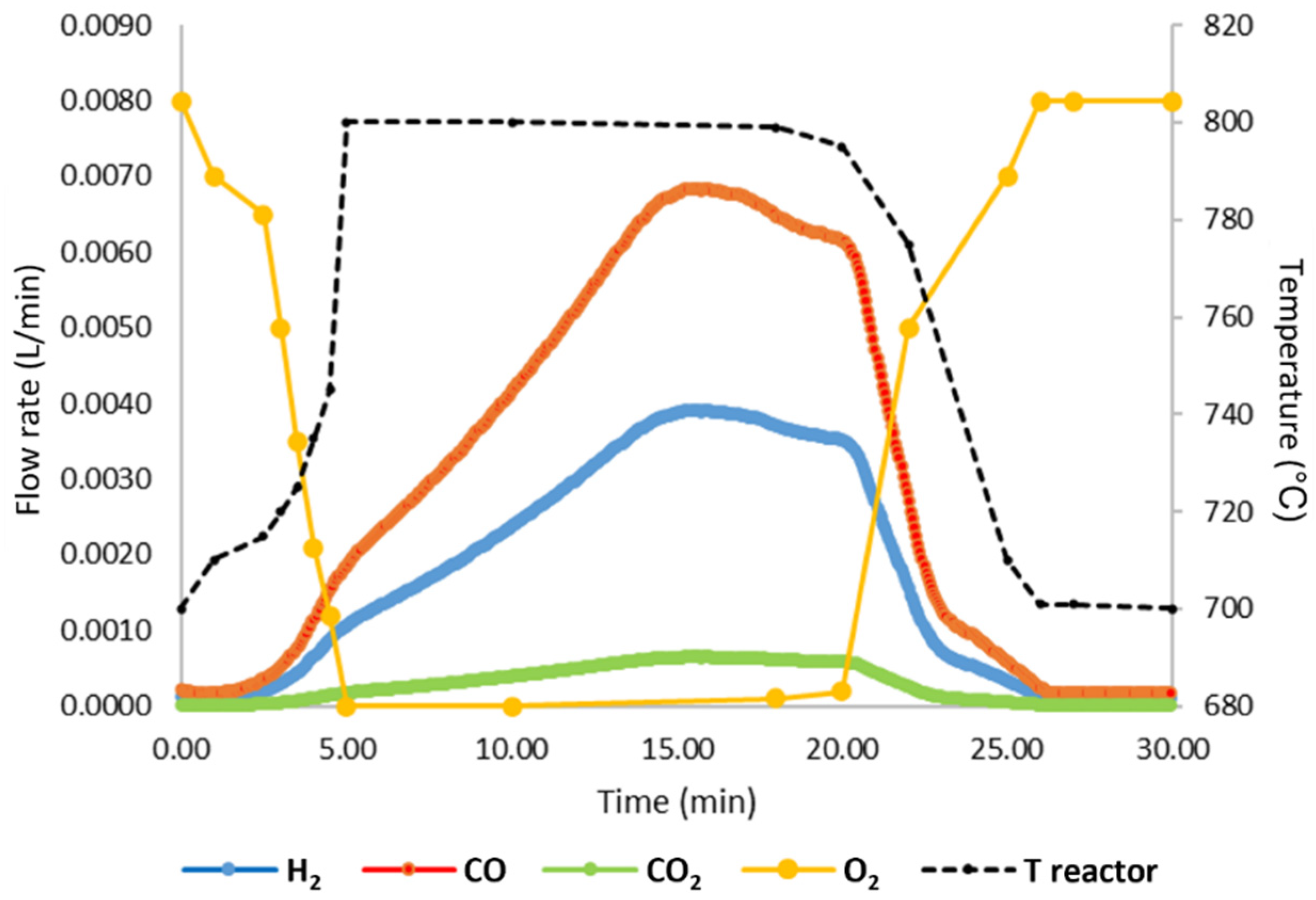
Considering that the aim is to partially oxidize guaiacol into CO and H2, the air flow rate is halved and fixed to 40 mL·min−1.
Figure 3 reports the variation in the main compounds detected in the gas phase (H
2, CO, CO
2 and O
2) and the temperature profile of the fixed bed during the test.
As reported in
Figure 3, by feeding 40 mL·min
−1 of air, it is possible to obtain a high reducing power gaseous stream, mainly constituted of CO and H
2, and low amounts of CO
2. The oxygen is totally consumed and is not present in the exiting gases for the first 15 min; after this time, it begins to be revealed, meaning that almost all the guaiacol was consumed. A significant increase in the reactor temperature from 700 to 800 °C is reached thanks the high exothermic nature of the combustion reactions. This additional heat led to an increase in the reaction temperature, promoting kinetics of the iron oxide reduction, especially with solid carbon, if present. During this step, in fact, solid carbon can be deposited on the Fe-based particle layer since, when the NiO/Al
2O
3 bed with guaiacol adsorbed is heated, part of the guaiacol can be desorbed and flow with the gas phase can undergo cracking reactions, causing the deposition of carbon on the Fe-based particles; the presence of this carbon in order to produce pure H
2 in oxidation should be completely consumed by reduction reactions in order to avoid its presence in the oxidation step, in which it can reacts to give CO, undermining H2 purity. The main reactions taking place in the reduction step are reported below (reactions (3)–(14)) [
29].
3.4. Steam Oxidation for Pure H2 Production
The last step of the process consists of the steam oxidation of the reduced iron oxides at 700 °C. The goal of this step is to oxidize the reduced Fe in order to produce pure H
2 by water splitting according to the reactions (15)–(17) [
30].
The oxidation with water vapor is not able to completely restore the Fe to Fe
2O
3; therefore, during this step, Fe
3O
4 is produced [
31].
This step is, therefore, conducted with a double-layer (NiO/Al
2O
3+Fe-based particles) fixed bed.
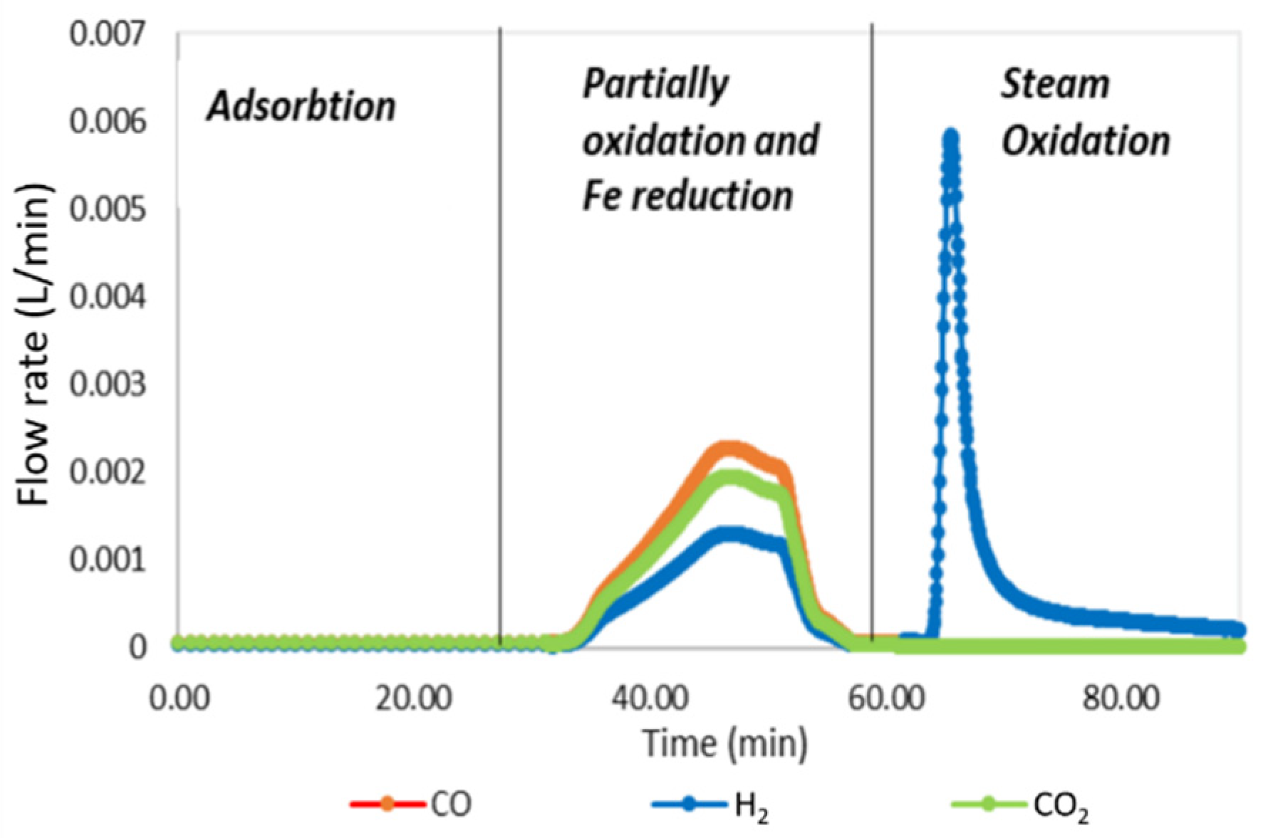
Figure 4 shows the flow rates of the main compounds (H
2, CO, CO
2) detected in the gaseous phase in the three steps of the process.
The results reported in
Figure 4 demonstrate the feasibility to reduce iron oxide using the gas stream generated by the partial oxidation of the guaiacol adsorbed on NiO/Al
2O
3 particles. In the oxidation step, the hydrogen produced is pure, meaning that in the first cycle, carbon-based compounds are not present or, if present, the carbon is in a form that cannot be easily oxidized by water at the operating conditions adopted. To evaluate the reduction degree of iron oxides during the partial oxidation step, the steam oxidation efficiency (
E%) is calculated according to Equation (18):
where
VH2 is the volume of H
2 obtained during the steam oxidation step and
VH2 theoretical is the maximum amount of H
2 producible, considering the total reduction of iron oxides to metallic iron and the total oxidation of Fe to Fe
3O
4. The calculated steam oxidation efficiency is equal to 35%. The results suggest that the complete reduction to metallic iron is not reached and that the amount of reducing agents produced from partial guaiacol oxidation are not sufficient to achieve the complete iron oxide reduction at the operating condition adopted. However, the produced H
2 has high purity (CO < 10 ppm) and, thus, it can be utilized in a large variety of applications (Automotive, chemical industry).
3.5. Stability Test
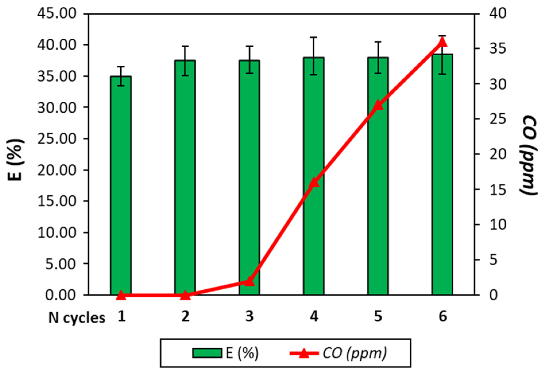
To evaluate the feasibility of the process and the resistance of the Fe-based particles, a test with six cycles is conducted. Each cycle includes the guaiacol adsorption, guaiacol partial oxidation and Fe reduction and oxidation by water vapor. The results of the stability tests in terms of process efficiency and hydrogen purity are reported in
Figure 5.
As already said, the efficiency of the first cycle is 35% and an increase in the efficiency to 38% is registered. This phenomenon was expected since, after the first cycle, the Fe-based particles in oxidation form are composed of Fe
3O
4 and, thus, a lower amount of reducing gases is needed to reach metallic Fe. However, the efficiency is still low, meaning that the reducing form of the particle is not Fe. The efficiency is stable for the six cycles, meaning that the synthetized 60 wt% Fe
2O
3/40 wt% MgO particles possess good thermal stability. The addition of MgO to Fe
2O
3 increases the resistance of Fe
2O
3 to high temperature [
32]. However, after three cycles, CO begins to be produced, undermining the H
2 purity, and after the third cycle, the CO concentration overtakes the limit of 10 ppm if the H
2 must be used for fuel cell application, for example. This result suggests that in the Fe particle bed, carbon is present and its amount tends to increase cycle after cycle.
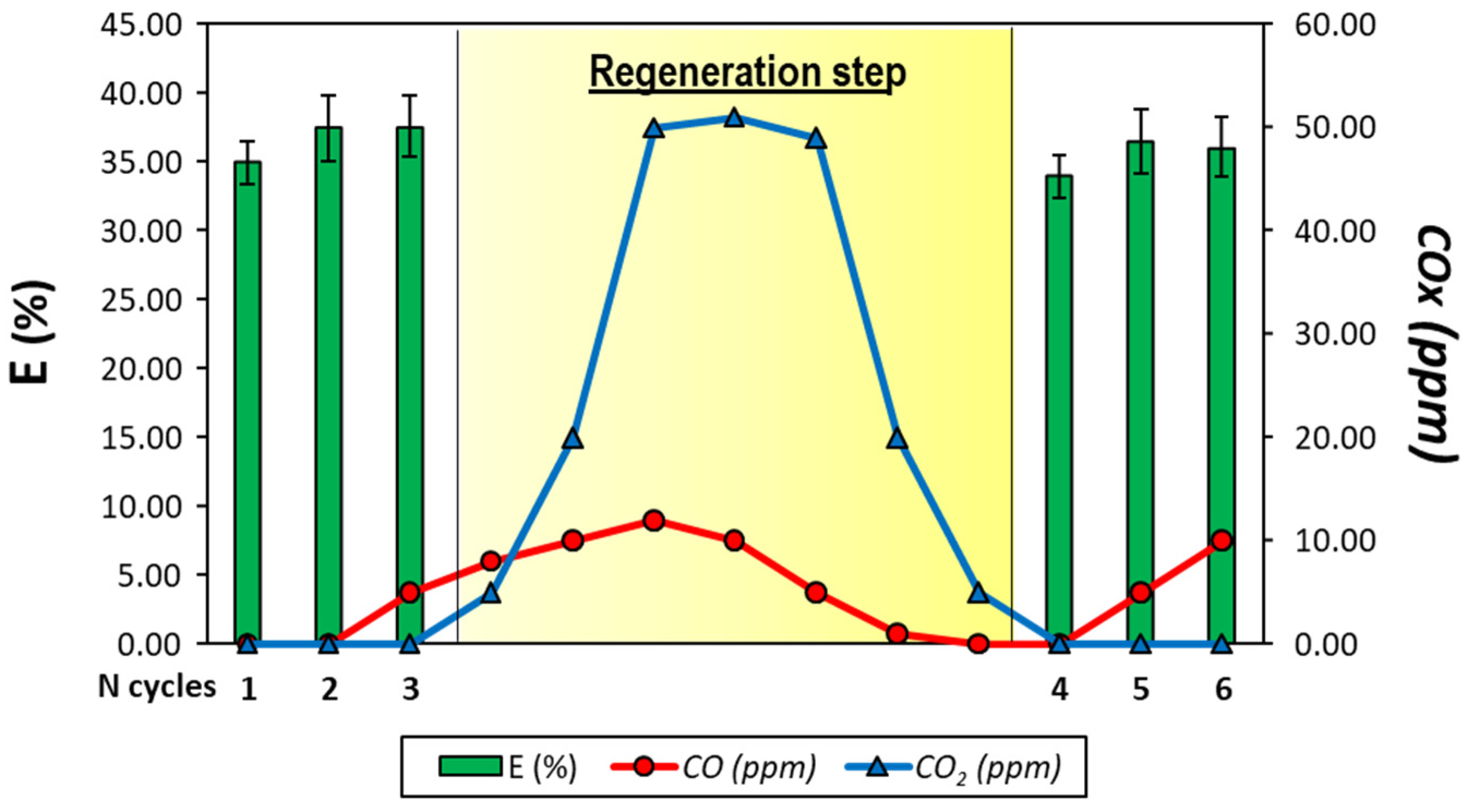
To solve this issue and to guarantee the H
2 purity, the six-cycle test is repeated but after the third cycle, a diluted air flow (oxygen concentration 10%) is fed to the reactor in order to burn all the carbon deposited. The regeneration step lasts 7 min, until the CO
2 concentration falls to 0. The results are reported in
Figure 6 and, as expected, the hydrogen purity in this way is guaranteed. In this way, the CO concentration never exceeds 10 ppm.
As can be seen from
Table 4, the feasibility to remove tar from syngas by chemical looping technologies was already demonstrated. However, the data reported highlight that the use of a chemical looping hydrogen process can maximize the tar removal efficiency, obtaining a separated pure H
2 stream.
4. Characterization of the Fe-Based Particles after the Three-Step Redox Cycles
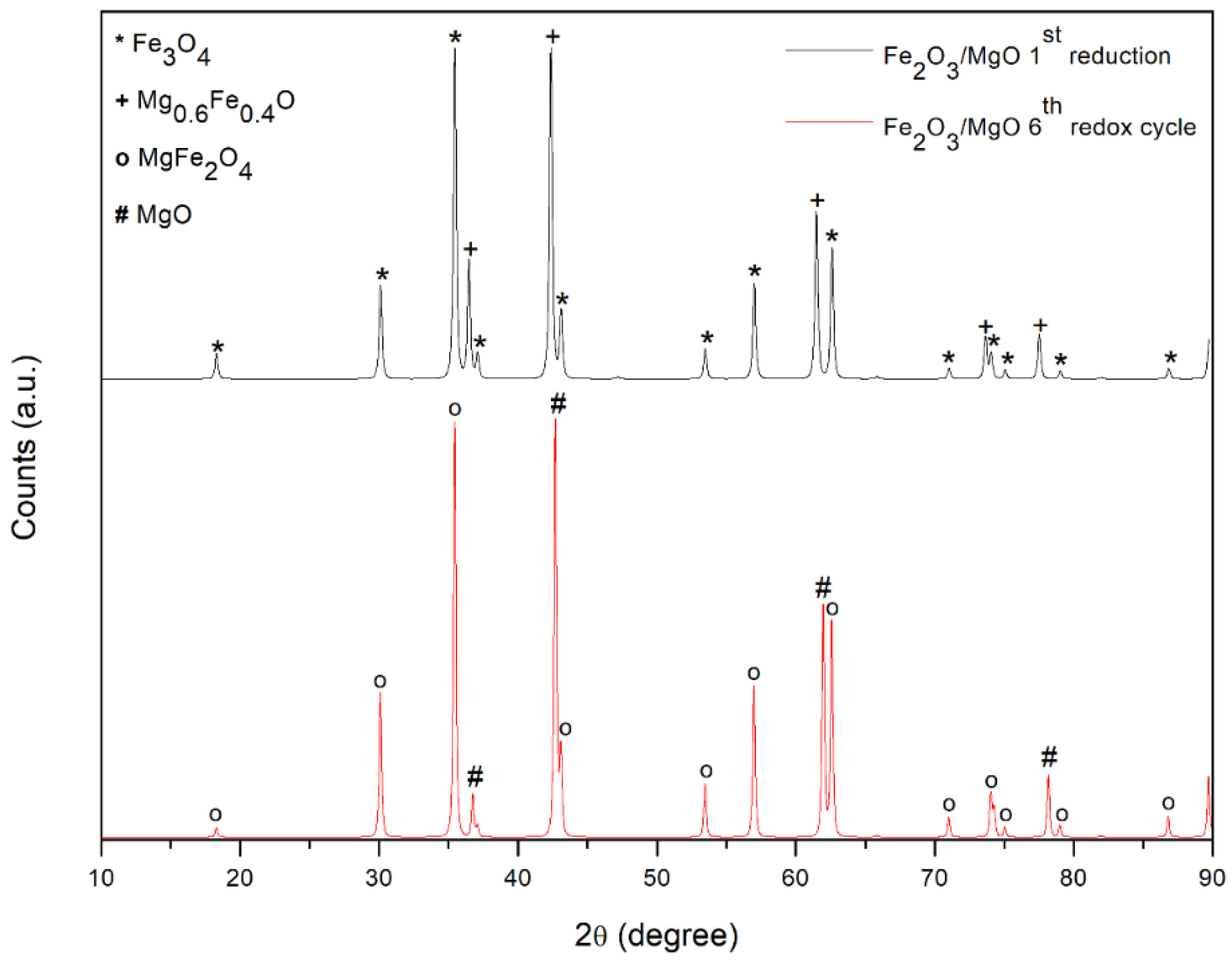
XRD analyses are conducted on the synthetized Fe-based articles before and after the three-step tests in order to better understand the behavior of the redox material in the process. As discussed in
Section 3.1, a strong interaction between Fe
2O
3 and MgO is detected after calcination in air at 900 °C; magnesium oxide and iron oxide form a spinel structure. Magnesium ferrite (MgFe
2O
4), which is one of the most important ferrites that finds a wide number of applications in heterogeneous catalysis, is observed in the sensor sector and in magnetic technologies [
37]. These interactions modify the redox system of the Fe
2O
3 and MgO; in fact, looking at
Figure 7, after reduction, iron is reduced in two different structures. Part of the iron is present as magnetite and the other amount forms a mixed oxide, named magnesiowustite (Mg
0.6 Fe
0.4)O with oxidation state equal to +2. However, no iron signal is detected, confirming the incomplete reduction achieved in the three-step redox cycle test. At the end of the test, the sample is composed of MgFe
2O
4 and MgO and, therefore, it can be used in a subsequent cycle. The mean crystallite size calculated from the Scherrer equation is 177.1 nm for the spinel phase and 403.1 nm for MgO.
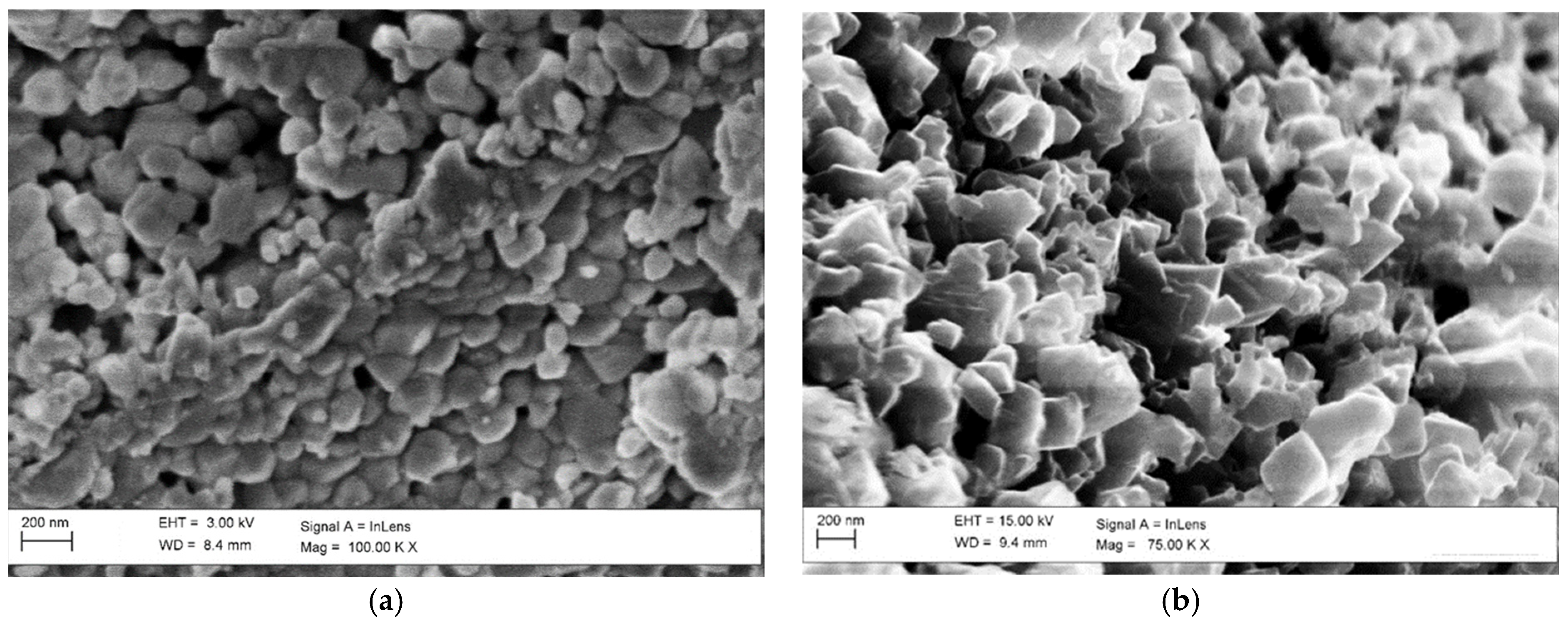
Looking at the SEM pictures reported in
Figure 8, the high thermal stability of this material is confirmed. It can be noted that the dimension of particles suffered a slight increase in size; the crystallites in the sample are clearly visible also after the stability test, meaning that any synthetization phenomenon can occur. This result confirms the positive effect of MgO addition on the activity and stability of iron oxides in the steam iron process.
5. Conclusions
In this work, an innovative syngas cleaning process was studied, demonstrating the feasibility of using tar as a reductant agent for chemical looping hydrogen processes. The aim is to remove tar from syngas, converting it into pure hydrogen. The proposed process consists of three steps (tar adsorption, guaiacol partial oxidation/iron oxide reduction and hydrogen production/iron oxidation) and to demonstrate the efficiency of each step, they were first studied independently. The adsorption efficiency of the NiO/Al2O3 bed was 98% when an amount of guaiacol equal to 2.731 mmol was fed. The partial oxidation of guaiacol to produce the iron oxide reducing agents was successfully tested; from the analysis, the iron oxides appeared to be partially reduced and an increase in the bed temperature of 100 °C was detected, favoring the reduction kinetics.
The efficiency of the process related to the hydrogen production after the first cycle was 35% and the amount of CO less than 10 ppm. Stability tests with six cycles were conducted, demonstrating that the synthetized material possesses a great resistance to thermal stability. However, after two cycles, the amount of CO in the produced H2 stream begins to increase due to the accumulation of unreacted carbon in the Fe particle bed. The introduction of a combustion step in the process, aimed at cleaning the iron-based particles from carbon, was successfully tested, obtaining a continuous production of pure H2.
The results reported in this study demonstrate that the chemical looping hydrogen process can be a very interesting alternative to recover the energy contained in tar by using it to produce pure hydrogen. In this way, the efficiency and the flexibility of the whole gasification process can be considerably improved; in fact, with this configuration, it is possible to produce clean syngas enriched with hydrogen but also two high-value separated streams: syngas and pure hydrogen, exploitable in a great number of applications.


