Article

Insights of Selective Catalytic Reduction Technology for Nitrogen Oxides Control in Marine Engine Applications

by
Pierpaolo Napolitano
1,
Leonarda Francesca Liotta
2,
Chiara Guido
1,
Cinzia Tornatore
1,*,
Giuseppe Pantaleo
2,*,
Valeria La Parola
2 and
Carlo Beatrice
1
1
Istituto di Scienze e Tecnologie per l’Energia e la Mobilità Sostenibili (STEMS-CNR), Via Marconi 4, 80125 Napoli, Italy
2
Istituto per lo Studio dei Materiali Nanostrutturati (ISMN-CNR), Via Ugo La Malfa 153, 90146 Palermo, Italy
*
Authors to whom correspondence should be addressed.
Catalysts 2022, 12(10), 1191; https://doi.org/10.3390/catal12101191
Submission received: 2 September 2022 / Revised: 3 October 2022 / Accepted: 5 October 2022 / Published: 8 October 2022
(This article belongs to the Special Issue Catalytic Removal and Resource Utilization of NOx)

Abstract

:
The international shipping industry is facing increasingly stringent limitations on nitrogen oxide (NOx) emissions. New solutions for reducing NOx emitted by marine engines need to be investigated to find the best technology. Selective Catalytic Reduction (SCR) is an advanced active emissions control technology successfully used in automotive diesel engines; it could be applied to marine engines with ad-hoc solutions to integrate it in the exhaust of large engines. In this study, a commercial SCR was tested at the exhaust of a diesel engine in inlet gas conditions typical of a marine engine. The SCR system consisted of a custom monolith (provided by Hug-Engineering AG) that enabled seamless integration for a broad range of engine sizes; the active phases were V2O5 (3 wt%)-WO3 (7 wt%)-TiO2 (75 wt%). The monolith was studied at the laboratory scale for its in-depth chemical/physical characterization and by means of an intermediate-scale engine, reproducing the exhaust gas conditions of a full-scale marine engine. The system’s effectiveness in terms of NOx removal for the selected engine operating conditions was evaluated in a wide range of temperature and NOx emissions values and for different quantities of the reduction agent (AdBlue or ammonia) added to exhaust gases. The investigated technological solution resulted in efficient NOx emission control from a marine engine.

1. Introduction

Marine diesel engines have always used heavy fuel oil, a poor-quality fuel that contains a high concentration of sulfur; therefore, among the pollutants produced, sulfur oxides (SOx) are of great importance, together with nitrogen oxides (NOx) and particulate matter (PM) [1]. Nitrogen oxides have a major impact on air pollution. They can damage the human respiratory system, promote secondary organic aerosols, acid rain and haze photochemical smog and contribute to ozone depletion [2]. NOx emissions from marine engines have been recently taken into consideration by the Tier III standards of the International Maritime Organization (IMO), introduced on January, 1st 2016 (MARPOL Annex VI). These regulations require an 80% reduction in NOx emissions compared to Tier I, and they apply in selected sea areas called “NOx Emission Control Areas (N-ECAs)” that comprise the coastal waters of the United States and Canada, the North Sea and the Baltic Sea. In addition to the IMO conventions, other maritime organizations such as the United States’ Environment Protection Agency (EPA), the European Union and the Chinese Ministry of Environmental Protection have also established maritime regulations for the reduction in exhaust emissions [3].
Exhaust gas aftertreatment devices can efficiently remove pollutants from internal combustion (IC) engines’ exhausts without a penalty in engine power and fuel economy. Among them, selective catalytic reduction (SCR) systems are widely adopted in road applications for effectively reducing NOx. SCRs can operate as a standalone technology; they show high levels of reliability and durability, and they do not require major engine modifications. This technology includes an injection of urea water into the exhaust gas; taking advantage of the exhaust gas heat, ammonia (NH3) is produced through urea thermal decomposition. NH3 reacts with NOx on a catalyst to convert NOx into molecular nitrogen (N2) and water (H2O). The main global reactions occurring in a SCR are presented in Table 1.
Reaction (a) represents the overall stoichiometry of the SCR process; it occurs rapidly in the presence of catalysts when the temperature is between 250 and 450 °C and oxygen is in excess. Usually, NO2 concentration at the exhaust is very low (only 5% of the NOx), so reactions (b) and (c) play a minor role in the process.
As for the undesired oxidation reactions, those indicated with the letters d-f involve NH3 consumption and determine a reversal of NOx removal and the formation of N2O as a by-product. These reactions can take place on SCR catalysts when the feed is low in NO, but they are negligible in the presence of NOx.
Ammonia has been chosen as reducing agent in the SCR process due to its capability to selectively react with NOx in excess of oxygen. This property is not observed in other simple reagents such as hydrocarbons and carbon monoxide. Reaction (g) is the oxidation of SO2, responsible for the formation of salts such as ammonium sulfate [4].
The core of the SCR technology is the catalyst system that has the role of improving the reaction efficiency by decreasing the activation energy and reaction temperature of NOx decomposition, increasing N2 selectivity in NOx reduction products and preventing the incidence of side reactions. Selecting the appropriate catalysts is critical when designing an SCR; its main characteristics should be high deNOx activity, strong anti-poisoning ability, high mechanical strength and a suitable operating temperature range [5]. Many catalysts have been demonstrated to be effective in SCR reactions. Noble and transition metal oxides are the primary active components, with TiO2, Al2O3, SiO2, zeolite and carbon serving as carriers.
For low- and medium-speed marine engines, SCR technology is derived from power plant systems using diesel engines. While ammonia water can be used in power plants as a reducing agent, larger ships only use urea water solutions [6] for safety and storage reasons. The size of the urea–SCR system can also be an issue; the SCR urea consumption is estimated to be 8.5% of the diesel consumption [7]; this undoubtedly adds size and weight to the ship. Furthermore, the vibration resistance of urea tubes should be carefully considered. Pumping and dosing systems, as well as urea feed pipes, use welding connections whenever possible to avoid urea leaks [8].
Furthermore, the main challenges for marine SCR applications are low temperature sulfur resistance and low temperature activation. The latter issue is also a problem for cars, trucks and off-road applications and can result in the catalyst not working, for example at startup and during maneuvering [9]. In marine engines, the turbine downstream temperatures are generally below 150 °C, making catalytic exhaust gas treatment impossible. For this reason, the SCR catalyst is usually placed on top of the turbocharger close to the engine to allow the highest possible temperature for an efficient NOx conversion and to avoid the formation of ammonium sulfates. In this case, the system is called high-pressure SCR (HP-SCR) and it is mostly used for two-stroke low-speed diesel engines. HP-SCR is characterized by a compact layout and high exhaust gas energy utilization rate, but it has a significant impact on the working performance of diesel engines and turbochargers. Conversely, an SCR arranged after the turbocharger is referred to as low-pressure SCR (LP-SCR). This system has high adaptability and a lower impact on the engine and turbocharger but its denitration efficiency is inadequate for low-speed two-stroke diesel engines because of the low exhaust temperatures. For this reason, an exhaust gas heating device is usually installed before the SCR reactor [10]. In the frame of the above literature, it emerges that the investigation of NO SCR catalysts for marine applications and the issues related to on-board installation deserve further efforts. Some numerical investigations have recently been performed to predict the denitration efficiency, ammonia flow rate and other parameters of SCR systems for marine applications [11,12]; less effort has been made for experimental studies.
Most catalysts for marine SCRs are V2O5–WO3–TiO2-based; vanadium and tungsten oxides coated on a titanium substrate [13]. V2O5 is the active component (1–3%), which is usually impregnated on an anatase TiO2 support together with WO3 (~10%) to stabilize the vanadia and increase thermal durability. The typical maximum NOx conversion range is between ~250 °C and ~450–500 °C. Above this temperature, selectivity is reduced because NH3 is oxidized by O2 instead of reacting with NO [14]. A V2O5–WO3–TiO2 SCR is commonly used as a stationary catalyst, but it has not been commercialized for vehicles due vanadium toxicity. Conversely, this type of SCR catalyst is appropriate for ships because of its high light-off efficiency, good sulfur resistance and low cost, so its demand in the market has increased.
It is worth noting that zeolite-based catalysts can also be effective in catalytic exhaust gas aftertreatment systems because they are characterized by a high specific surface area and thermal stability. In recent years, many studies have improved the de-NOx performance and durability of Cu-zeolite catalysts that show excellent low temperature activity [15,16,17,18]. Fe-zeolite has great durability toward high temperature and poisoning; thus, it can be successfully used in after-treatment catalysts for heavy-duty diesel engines even if it shows a high activation energy, causing low light-off performance.
Some researchers have compared V2O5–WO3–TiO2 catalysts [19] with two kinds of Fe-zeolite (Fe-zeolite (1) and (2)). Their physicochemical characteristics were examined according to hydrothermal aging, sulfur poisoning and HCs co-existence. The results showed that V2O5–WO3–TiO2 SCR was the least susceptible to sulfur poisoning because of Brønsted acid site effects and its NOx conversion rate was relatively higher at ~350 °C. It resulted in being the most suitable for the reduction in exhaust gas from ship engines.
Magnusson et al. [12] investigated how sulfur, water and low temperature affect NOx the reduction activity of a commercial SCR V2O5–WO3–TiO2 catalyst in marine applications using urea as a reducing agent. The authors proved that for temperatures higher than 300 °C, NOx reduction could be greater than 90%. Japke et al. [20] tested the performance of vanadia-based SCR catalysts obtained using the incipient wetness impregnation method. The study demonstrated that the preparation process had a strong effect on the catalyst’s NOx removal efficiency with ammonia and on the oxidation activity of soot and hydrocarbons. Zhou et al. [21] studied the catalytic activities of an extruded commercial monolithic V2O5–WO3–TiO2 catalyst at low temperatures according to the working characteristics of marine diesel engines. The authors reported that for temperature below 150 °C, the SCR reaction was mostly influenced by internal chemical reaction kinetics, and when the temperature was above 200 °C, the most relevant mechanism affecting the SCR reaction was the reactant diffusion rate. The parameters that can improve NOx reduction were found to be space velocity, NH3 consumption and O2/NO2 concentration in the gas mixture.
Recently, Lai et al. [22] and Zhang in collaboration with some authors of the present paper [23] have pointed out that the catalyst’s preparation method, the titania surface area and crystalline structure, the vanadium and tungsten loadings and the calcination treatments strongly affect the morphological, structural, acidic properties and NO SCR performance.
The unequivocal result emerging from all the studies is the crucial role played by the titania support with the capability to establish a proper interaction of the V2O5 and WO3 active phases. Moreover, the shape and nature of the monolith, as extruded or wash-coated by the active phases, and its manufacturing procedure are undoubtedly key factors.
On these bases, we considered an extruded monolithic catalyst worthy of investigation, provided by Hug Engineering AG (Elsau-Switzerland) containing V2O5 (3 wt%)-WO3 (7 wt%)-TiO2 (75 wt%), rest bentonite and glass fiber as the active phases. Such a catalytic device that normally is used for the abatement of NOx from stationary sources was firstly characterized in terms of its physical-chemical properties at laboratory scale. Then, it was installed and tested at the exhaust of a diesel engine in exhaust conditions representative of a marine on-board power generation engine. This kind of engine was equipped with high-pressure common rail injection systems and worked with low-sulfur diesel fuel (EN590).
The adopted methodology led to an assessment of the applicability and potentiality of the system when installed on a real engine, enlarging the scientific literature with quantitative data and information. Once the good potentiality of the system was revealed, the next step of investigation regarded the analysis of other aspects important for a future installation at the exhaust of marine engines, i.e., the poisoning resistance of the system and its thermal management. An experimental/numerical approach will be useful to enlarge the systems working conditions.
The results presented in this study are part of a wider project devoted to investigating low-impact technology solutions for power generation in marine applications.

2. Experimental Setup and Procedures

The methodology approach foresaw two different steps of investigation.
The study was initially conducted for a complete characterization of the physical-chemical properties. In this sense, the catalytic system was analyzed, as slab and/or as powder, in terms of the crystalline structure of the monolithic catalyst, specific surface areas, pore volume, pore size of the material, reduction properties and surface composition by means of proper diagnostics techniques.
The second step consisted of investigating the potentiality offered by the same SCR on an intermediate-scale engine, reducing the complexity of a test campaign on a real-scale marine engine. The experimental procedure foresaw to firstly assess the representativeness of the intermediate-scale engine, identifying test conditions typical of a real use of an SCR. Then, a monolith, representing one element of a full-scale SCR, was installed at the exhaust of the intermediate-scale engine and was characterized in terms of its NOx reduction efficiency.
The aim of such a research approach was to guarantee an in-depth analysis of the monolith potentiality, correlating the monolith features with its measured performance. The two laboratory experimental set-ups, the adopted diagnostic techniques and instrumentation are described in the following sections.

2.1. Laboratory Scale

The SCR device, provided by Hug Engineering AG, had a monolithic structure, 200 cpsi and a geometric parallelepiped shape. The chemical composition, as certified in the data sheet, is listed in Table 2.
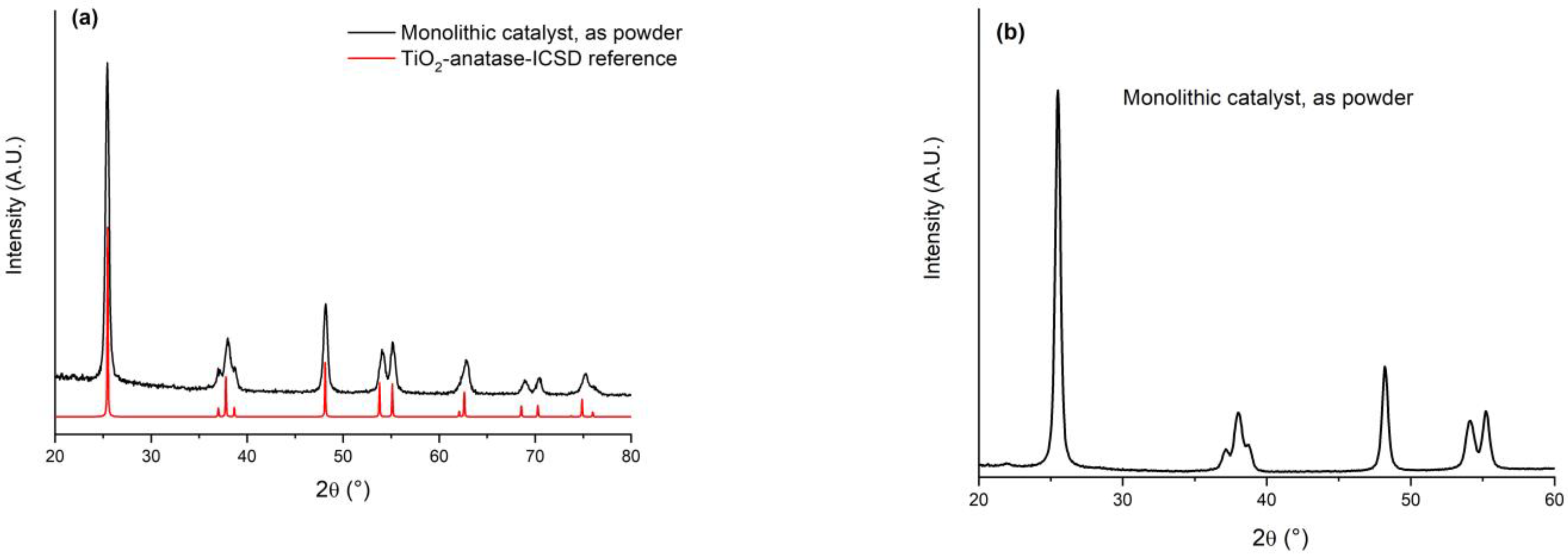
The crystalline structure of the catalyst (as a slab and as a powder) was determined by powder X-ray diffraction patterns (XRD), performed on a Bruker D5000 diffractometer equipped with a Cu Kα anode and graphite monochromator. The data were recorded in a 2θ range of 20–80° with a step size of 0.05° and time per step of 20 s. Moreover, a pattern with an acquisition time of 200 s/step was registered between 20 and 60° 2θ to confirm the absence of peaks ascribable to the V2O5 and/or WO3 phases. The only detected crystalline phases attributed to TiO2 were analyzed according to ICSD files (Inorganic Crystal Structure Database). The mean crystallite size was calculated by the Debye–Scherrer equation: D = 0.9λ/Bcosθ, where D represents the average crystalline size, 0.9 is the Scherrer parameter, λ is the wavelength of the X-ray radiation (0.15406 nm), B denotes the full width at half maximum of the peak (FWHM) and θ is the angular position of the peak.
The specific surface areas (SSA), pore volume and pore size of the material (as a slab and as a powder) were measured by N2 adsorption–desorption isotherms using a Micromeritics ASAP2020 system. Before analysis, the samples were degassed in vacuum at 250 °C for 2 h, then the measurement was performed at liquid nitrogen temperature (−196 °C). The Brunauer–Emmett–Teller (BET) method was used to calculate the SSA. The Barrett–Joyner–Halenda (BJH) method [24] was applied to the desorption branch to estimate the pore volume and pore size distribution.
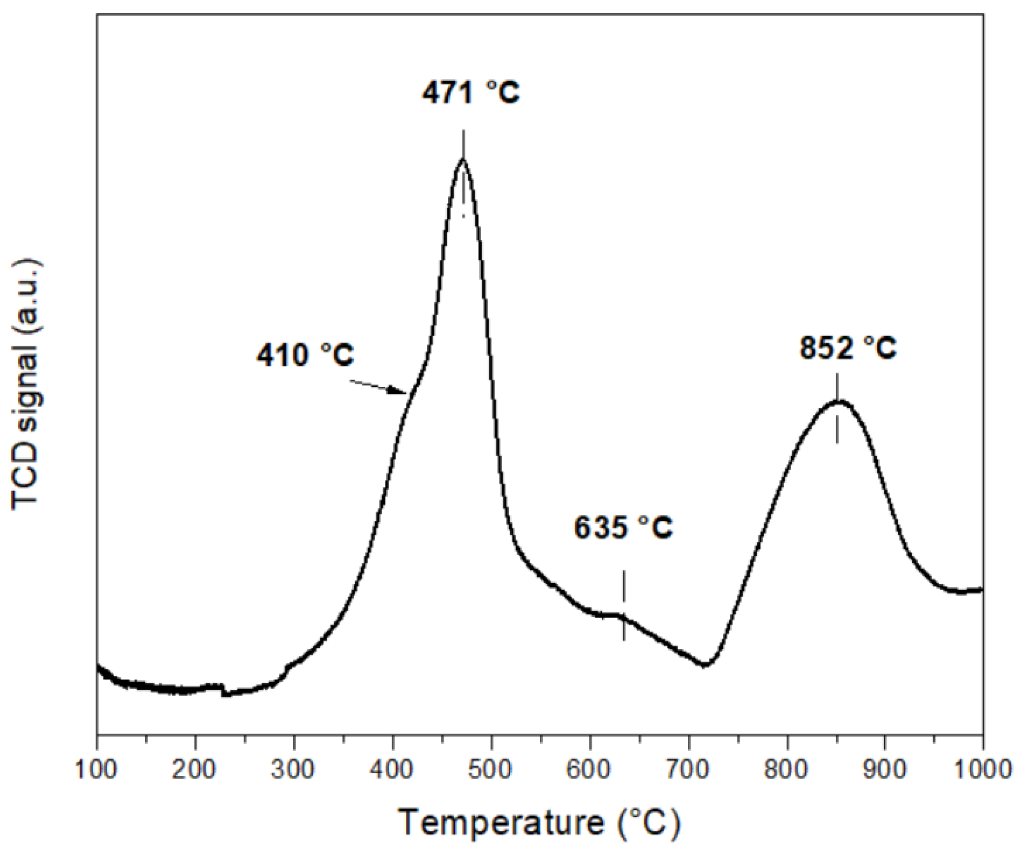
The catalyst (0.1 g), as a powder, was studied by hydrogen temperature-programmed reduction (H2-TPR) using Micromeritics Autochem 2910 HP apparatus equipped with a thermal conductivity detector (TCD). The H2-TPR profiles were registered after pre-treatment under O2/He flow from room temperature up to 300 °C with a holding time of 30 min. Then, after cooling down up to RT under He flow, the H2-TPR analysis was carried out in the temperature range of 25–1000 °C with a 10 °C min−1 heating rate and a flowing 5 vol.% of H2 in Ar (30 mL/min).
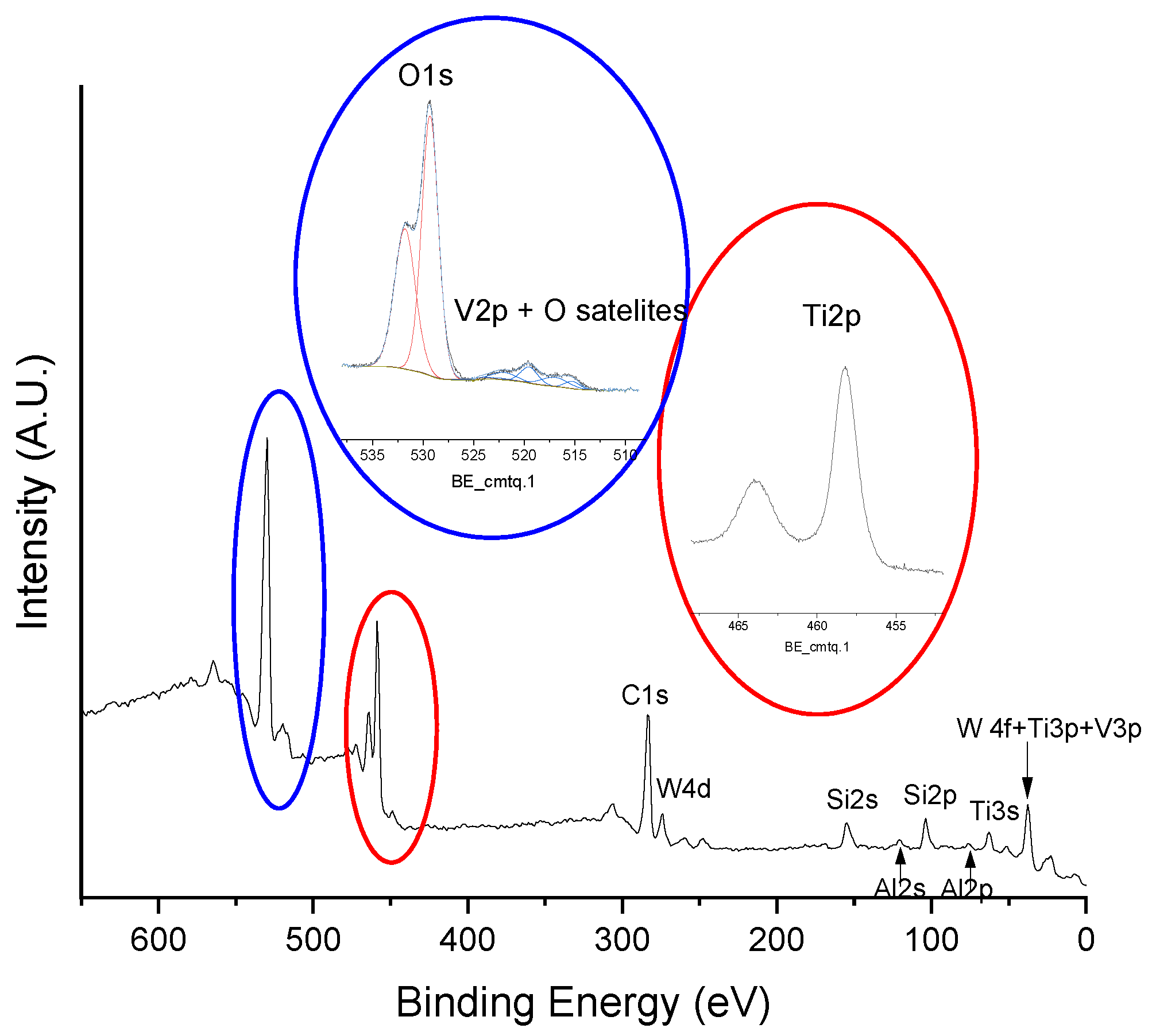
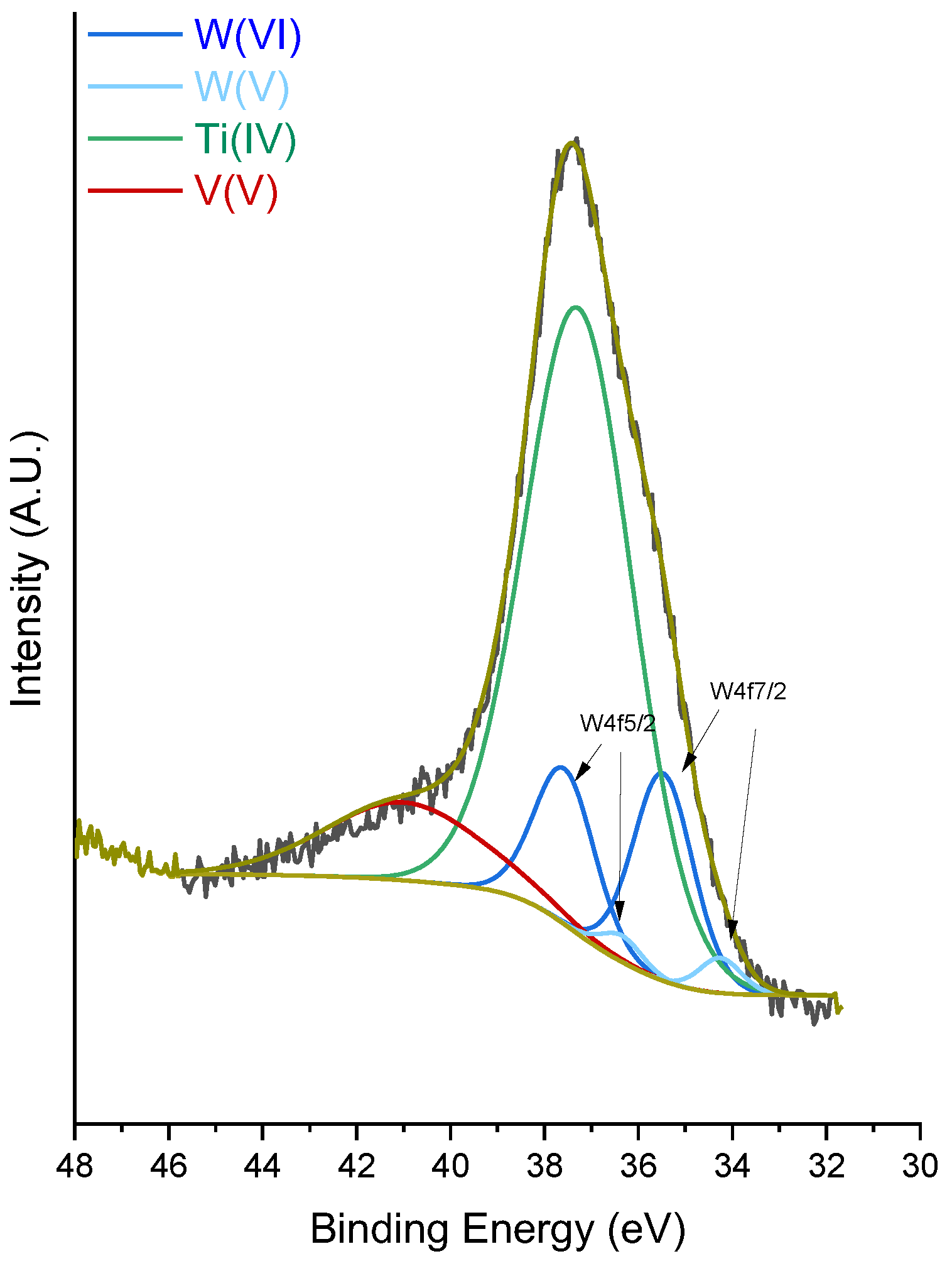
The X-ray photoelectron spectroscopy (XPS) analyses of the samples were performed with a VG Microtech ESCA 3000 Multilab (VG Scientific, East Grinstead, UK), using unmonochromatized Al Kα source (1486.6 eV) run at 14 kV and 15 mA and a CAE (Constant Analyser Energy) mode. A pass energy of 50 eV set across the hemispheres was used for the survey spectrum, and a value of 20 eV was used for the individual peak energy regions pass energy. The constant charging of the samples was removed by referencing all the energies to the C1s peak energy set at 285.1 eV, arising from adventitious carbon. Analyses of the peaks were performed using the CASA XPS software (version 2.3.17, Casa Software Ltd., Wilmslow, UK, 2009). For the peak shape, a Gaussian (70%)–Lorentzian (30%) line shape defined in Casa XPS as GL (30) profiles were used for each component of the main peaks after a Shirley type baseline subtraction. The binding energy values were quoted with a precision of ±0.15 eV and the atomic percentage with a precision of ±10%.

2.2. Engine Intermediate Scale

The final application of the prototype after-treatment device will be a marine engine, i.e., an ISOTTA FRASCHINI (IF) 4-stroke, water-cooled 8-cylinder V engine with 2 intake and 2 exhaust valves. The rated speed and power are 1500 rpm and 685 kW, respectively. The engine is equipped with a common rail injection system with electronic control and variable injection timing. The unit displacement is 3856.7 cm3 and the nominal compression ratio is 13.2.
Nevertheless, considering the size of the naval engine and the complexity and costs of the test campaign that would result, the characterization of the prototype after treatment device was carried out on an intermediate-scale (IS) engine; a heavy-duty engine for truck or bus applications, its main specifics are presented in Table 3.
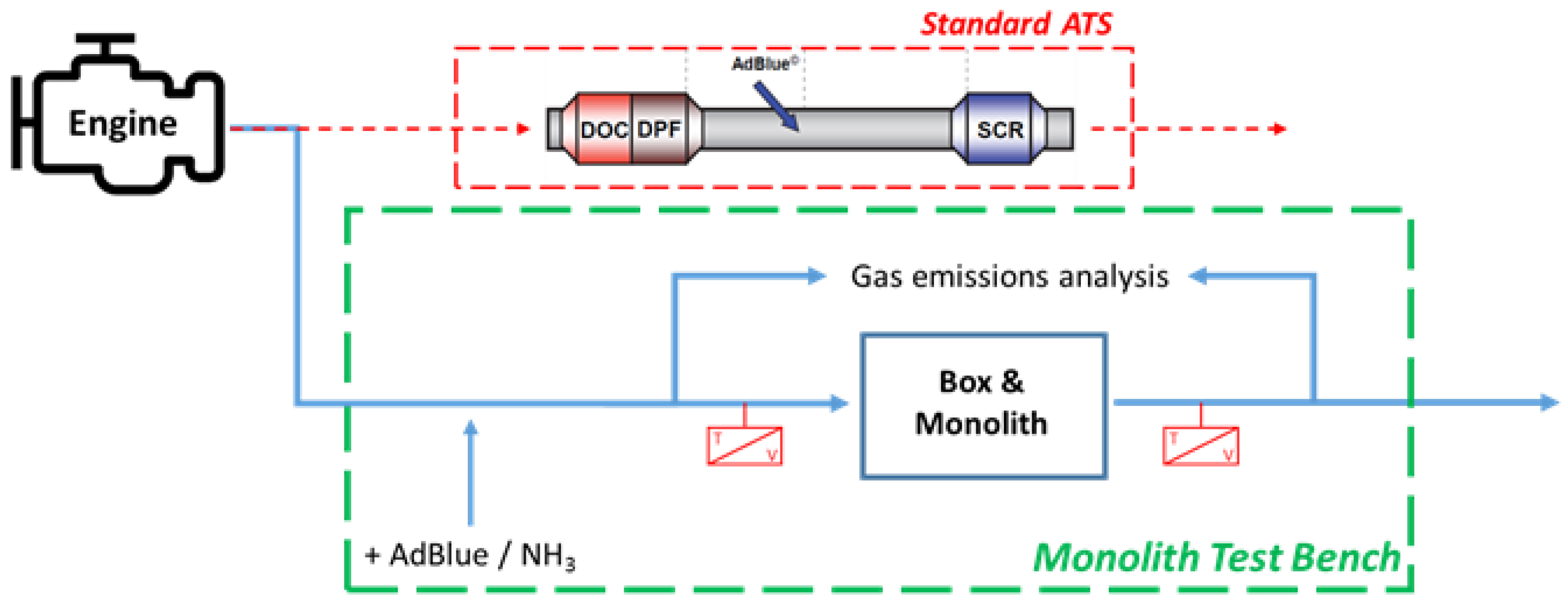
The IS engine was compliant with the latest anti-pollution regulations for road vehicles used in truck or bus applications (EURO VI). It was equipped with an after-treatment system consisting of a diesel oxidation catalyst (DOC), particulate filter (DPF) and nitrogen oxide catalyst (SCR). All these components were engineered in a single compact unit and real-time controlled by the engine control unit to ensure its efficient operation in the various working conditions. The engine was installed on a dyno test bench and instrumented for pressure and temperature characterization both at the intake and exhaust line.
At the engine exhaust, a smoke meter was used for smoke emission measurement, while the regulated gaseous emissions (THC, CO, CO2, NOx/NO, O
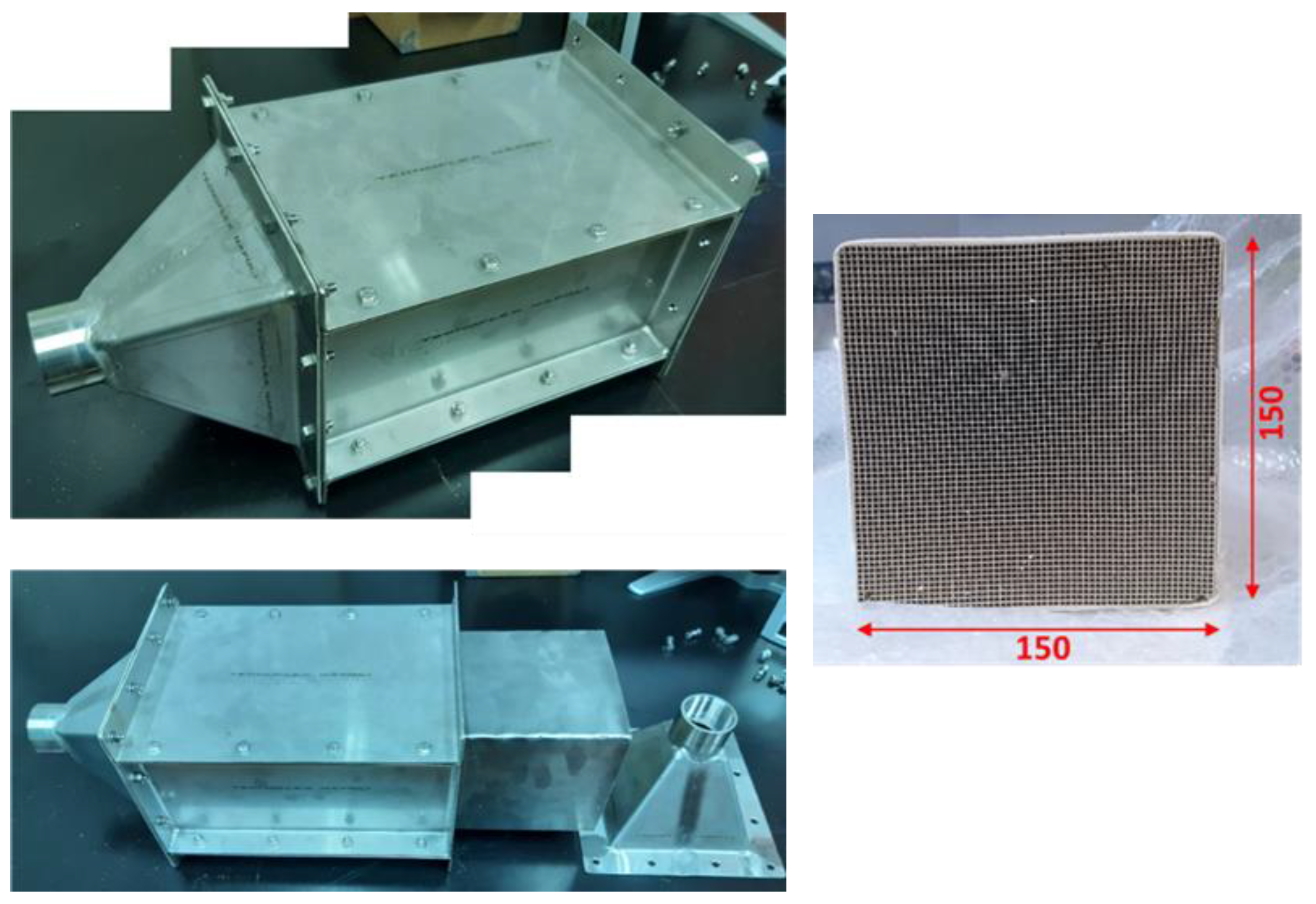
2) were measured upstream and downstream of the aftertreatment system with an exhaust gas analyzer bench (Horiba Mexa 7100). The parallelepiped-shaped SCR prototype was housed in the box shown in Figure 1, which was custom designed.
The engine exhaust line (originally providing a standard ATS layout) was properly modified to allow the SCR device installation. According to the scheme of Figure 2, the exhaust gas downstream of the turbine was driven to the new device by capping the original exhaust duct output.
The monolith had the following sizes: 150 × 150 × 300 mm and a volume of 6.75 dm3. The single monolith represented one of the twenty “bricks”, of which the catalyst for the reference marine engine should be constituted. This solution, although different from the typical layouts for road applications (cylindrical), could be the most suitable for a large and perhaps modular naval application.
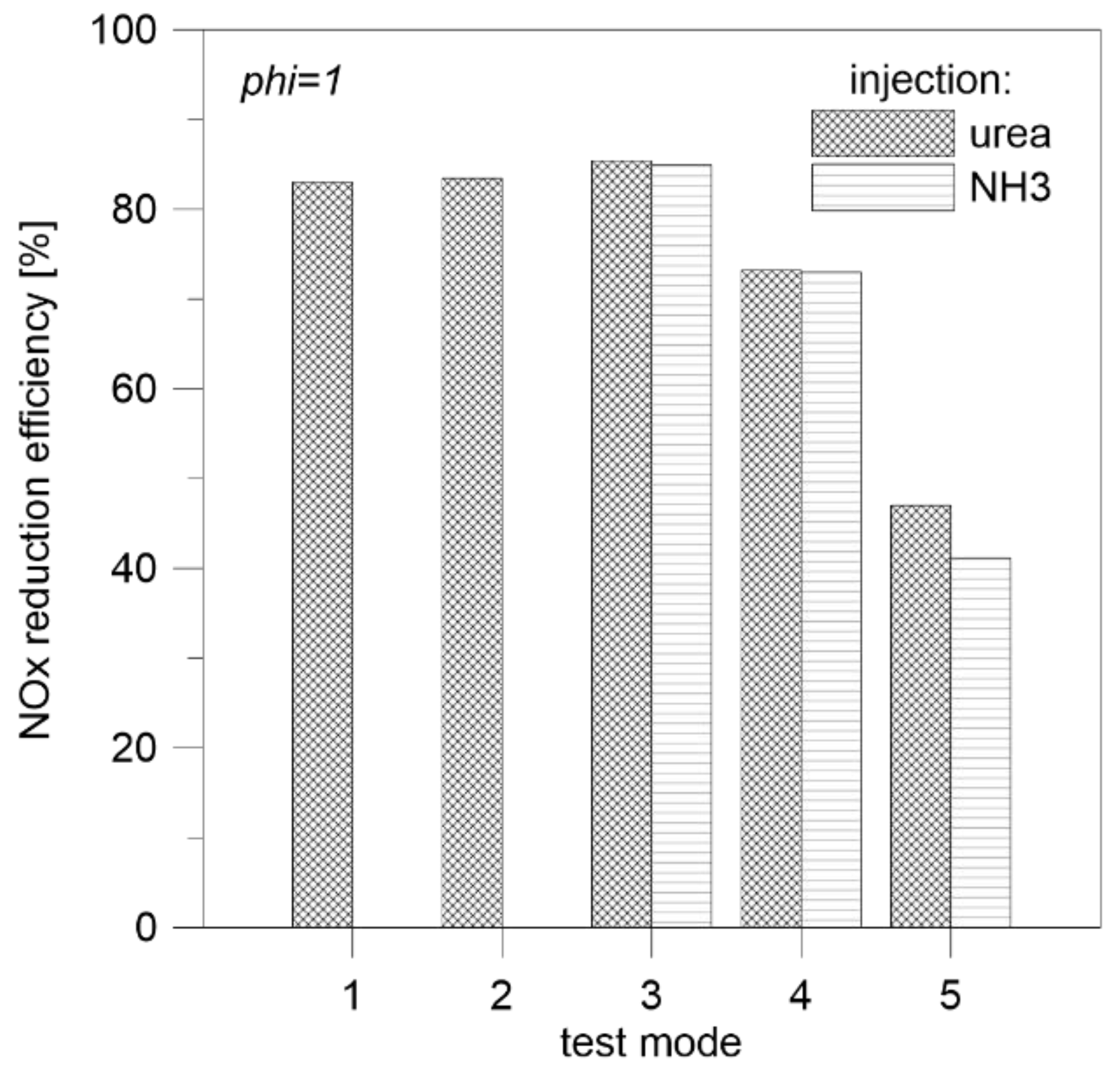
To stabilize the flow of exhaust gases and direct them to each part of the monolith, a connecting section with an exhaust manifold was designed. Due to the high temperature of the exhaust gases and to ensure the least interference from a chemical point of view with the gas stream, the whole exhaust line was made of stainless steel. The monolith box could be completely disassembled; this ensured easy and safe installation and replacement of the prototype to be characterized. For the SCR operation, a solution of water and urea was continuously nebulized in the exhaust gas stream; a standard urea injection system was used, consisting of an AdBlue tank, dosing unit, pressurization unit and an injector positioned along the exhaust duct. The injector actuation was controlled by the engine control unit and the AdBlue quantity could be properly dosed. In this way, it was possible to characterize the prototypes not only with respect to the quality of the exhaust gas (NOx concentration and temperature, which varied according to the engine point) but also to the concentration of reducing agent.
The test bench was equipped with the following sensors:
  • A thermocouple mounted at the entrance of the box to monitor the temperature of the inlet exhaust gases;
  • A thermocouple mounted at the outlet of the box to evaluate the temperature variation in the exhaust gases that cool down flowing through the SCR;
  • Exhaust gas sampling outlets “upstream” and “downstream” of the SCR to characterize the gas composition.
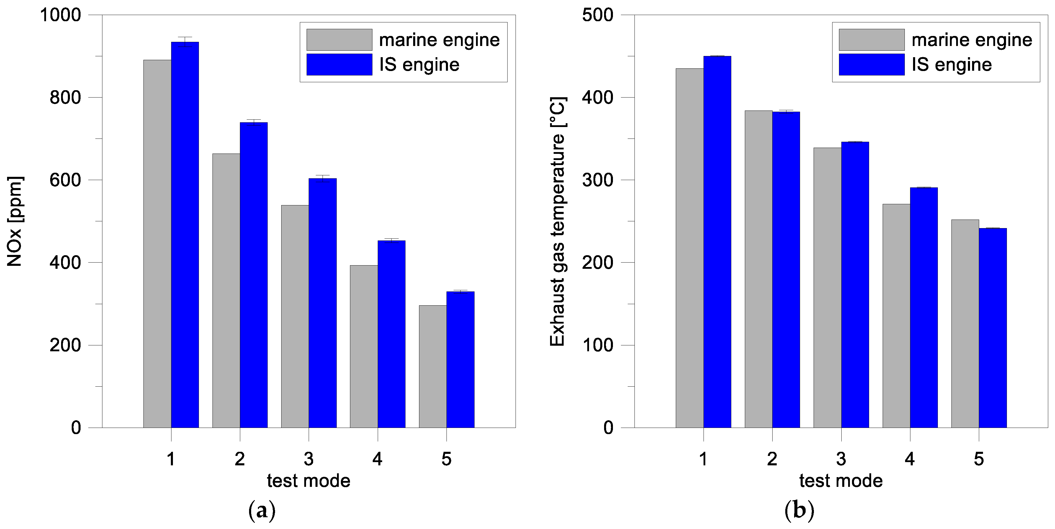
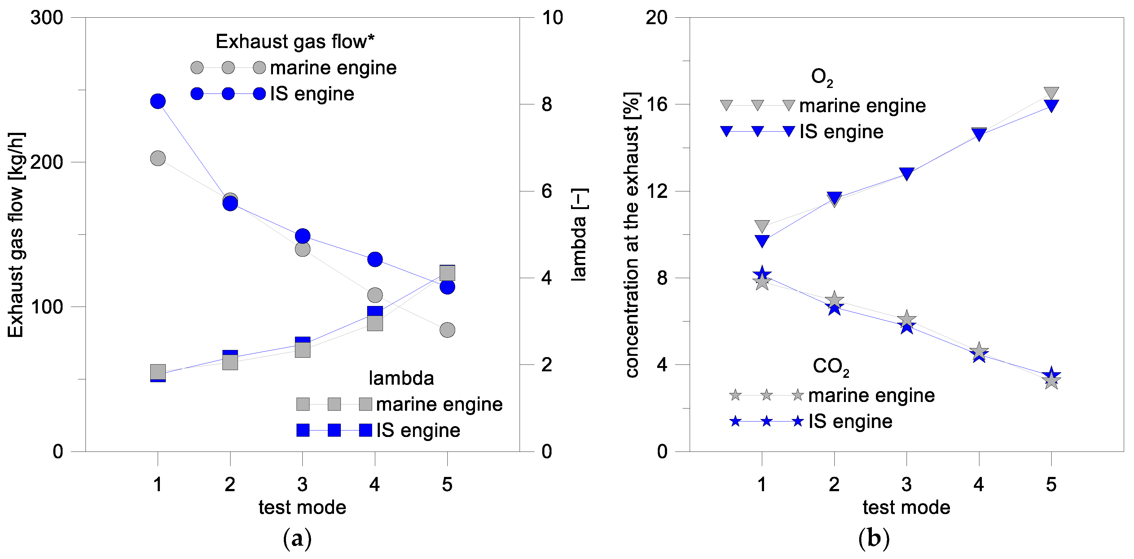
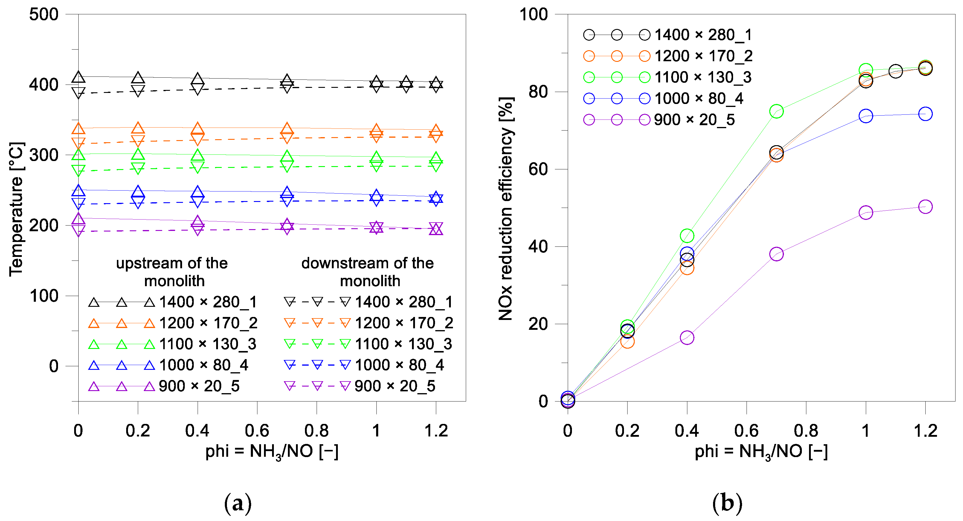
In a preliminary phase of this activity, the exhaust of the IF marine engine was characterized in the operating conditions representative of its standard working map in terms of flow rates, temperatures, gaseous pollutants and particulate matter concentrations, with the aim of subsequently reproducing such conditions at the exhaust of the intermediate-scale engine. E2/D2 test cycles were performed in controlled ambient conditions for five operating modes at a fixed speed of 1500 rpm and with torque values between 10 and 100%. The concentration of NOx, CO, CO2, THC, smoke and the thermodynamic properties of the exhaust gases were measured. Starting from this analysis, the first part of the experimental activity was aimed at the identification of five IS engine test points characterized by the same exhaust line conditions found during the above-described operation of the marine engine. Then, the experiments were focused on the characterization of the SCR prototype at the engine exhaust in the selected conditions.

3. Results and Discussion

3.1. Characterization of the Monolith

In order to investigate the crystalline structure of the monolithic catalyst, XRD patterns were registered on the powder and as well on the slab, for comparison. In Figure 3a, the diffractogram registered for the powder, in the angular range 20–80° 2θ, with a typical acquisition time of 20 s/step is shown. Only peaks of the anatase phase were identified by comparison with the ICSD reference of anatase (n. 9852, tetragonal, space group I 41/amdS), which is also displayed in the diffractogram. Similar results have been reported in previous work by some of the authors of this paper [25].
The absence of peaks ascribable to the WO3 and V2O5 phases was confirmed by recording a more detailed pattern with an acquisition time of 200 s/step in a selected angular range, between 20 and 60° 2θ (see Figure 3b), over a different portion of the powder. Identical XRD patterns showing only anatase peaks were obtained over the slabs of the monolith, confirming that the sample orientation did not affect the crystalline phases detectable. According with the literature, the absence of other crystalline phases, except those of TiO2, suggested the presence of WO3 and V2O5 as highly dispersed oxides or in an amorphous state. However, we cannot exclude that oxo-tungstate and V-O-W species were formed by the interaction of vanadium and tungsten with the support [26,27].
N2 adsorption/desorption isotherms were registered over the monolithic sample, as a powder and as slab pieces, to measure the specific surface area (SSA), pore size distribution and pore volume. The values are listed in Table 4 and showed a good correspondence for the two sets of data. In both cases, an SSA value around 56 m2/g was measured, which is typical of pure TiO2, such as Evonik P25 [28], with a mean pore size of ~15 nm and pore volume 0.21 cm3/g. However, differently from TiO2 P25, which is characterized by anatase and rutile phases, in the present monolith only anatase was detected (see Figure 3).
The reduction properties of the monolithic catalyst, as a powder, were investigated by H2-TPR analysis. A typical reduction profile registered for the monolith is displayed in Figure 4. According to the literature [21], the main peak centered at 471 °C was ascribed to the reduction of V5+ to V3+ corresponding to vanadia species highly dispersed over the titania surface, while the shoulder at 410 °C could be due to polymeric aggregates. Based on other investigations [29], intermediate oxides are formed during the reduction of V2O5 to V2O3 that could explain the asymmetric shape of the low temperature peak. By increasing the temperature, the reduction in mixed V-O-W species occurred at 635 °C, and then the broad peak at 852 °C was attributed to the reduction of W6+ to W4+ [21] or even to W0 according to other authors [30].
In Table 5, the hydrogen consumption values and the range of temperatures of the main peaks are reported. The experimental values are compared with the theoretical ones expected for the reduction of V2O5 to V2O3 and for the reduction of WO3 to WO2/W0, calculated based on the V2O5 and WO3 wt% of the monolithic catalyst (see Table 2).
Based on the values listed in Table 5, it can be deduced that the reduction of V2O5 to V2O3 was completed and, since the experimental consumption of 14.8 mL/g exceeded the theoretical one of 8.1 mL/g, it was expected that below 700 °C the reduction of some W also occurred, likely as mixed V-O-W species. At T > 700 °C, the consumption values of 17.3 mL/g suggest the occurrence of the reduction WO3 to W0, although in the extent of V and W reduction, we must keep in mind that some surface (at around 300–500 °C) and bulk reduction (at around 850–900 °C) of TiO2 took place [31].
The XPS analysis was performed on the monolithic catalyst as a slab in order to analyze the surface composition. Figure 5 shows the survey scan of the sample. The spectrum confirmed the presence of Ti, O, W, Si and Al according to the chemical composition, as reported in the data sheet. The main peak relative to vanadium (V2p) overlapped with the more intense O1s satellites arising from the Kα3, so it was not visible in the survey spectrum and its analysis was subjected to an important error (see blue inset, Figure 5). On the contrary, the region between 30 and 50 eV contained peaks relative to W4f, Ti3p and V3p, which were clearly distinguishable, so this region was used to analyze and quantify these elements. The results in terms of W4f7/2, V3p and O1s binding energies (eV) and surface W/Ti and V/Ti atomic ratios are listed in Table 6. Figure 6 shows the W4f, Ti3p and V3p region of the monolith. The spectrum showed a complex peak, which could be deconvoluted with two doublets due to the spin orbit splitting of W4f7/2 and W4f5/2 (spin orbit separation = 2.1 eV, W4f7/2–W4f5/2 area ratio of 0.75), along with a peak attributed to Ti3p and a peak due to V3p. According to the literature, the position of W4f7/2 of 35.5 eV was due to W(VI) while the W4f7/2 value of 34.3 eV was due to W (V) [32,33,34]. By deconvolution of the region, it was found that Tungsten was present mainly as W(VI) with a 10% presence as W(V). The V3p position was in accordance with the presence of V(V) [35,36,37]. Ti3p (37.2 eV) was in accordance with the presence of Ti (IV) [38,39]. This fact was confirmed by the analysis of the Ti2p region with the typical two peaks at 458.2 eV (Ti2p3/2) and 463.9 eV(Ti2p 1/2), see the red inset of Figure 5 [40]. Oxygen showed the typical profile of the TiO2 material with a component at ca. 529.5 eV due to its lattice and a component at 531.5 eV due to OH surface groups [35]. In Table 6, the surface atomic ratios of W/Ti and V/Ti are compared with the bulk values, derived from the real chemical composition as reported in Table 2. With respect to the calculated bulk values, the surface of the slab results was enriched in vanadium.

3.2. Monolith Performance at the Engine Exhaust

3.2.1. Selection of the Engine Conditions

In the first phase of the experimental campaign, five operating points (modes) of the intermediate-scale engine were chosen considering the following constraints with respect to the corresponding IF mode:
  • Exhaust flow scaled by 1/20;
  • Equal exhaust gas temperatures downstream of the turbine;
  • Same NOx concentration values;
  • Same O2 and CO2 concentration values;
  • Same air/fuel ratio.
The five intermediate-scale engine operating points, selected according to the experimental comparison between the two exhausts, are listed below, briefly indicated with the relative rotation speed (in rpm) and torque (in Nm):
Mode 1 1400 × 280
Mode 2 1200 × 170
Mode 3 1100 × 130
Mode 4 1000 × 80
Mode 5 900 × 20
The following figures report the comparison between the two engines behavior during the performed tests to demonstrate the reproducibility of the IF engine exhaust conditions in the intermediate-scale engine.
Tests repetitions were performed, and the standard deviation among all the IS tests is reported as error bars.
In Figure 7, the results obtained with the intermediate-scale (IS) engine in terms of NOx emissions (a) and exhaust gas temperatures (b) are compared with the corresponding results of the IF engine in the five selected operating points. The exhaust gas temperature was measured downstream of the turbine through a K-type thermocouple.
The test points selected for the IS engine ensured exhaust gas conditions capable of reproducing the NOx concentrations and temperature values measured at the engine exhaust of the full-scale marine engine. In this way, it can be assumed that the study of the reduced-scale SCR system was representative of the full-scale one since the concentration of nitrogen oxides and the exhaust gas temperature are the two main parameters that influence the efficiency of an SCR device.
Figure 8a shows the comparison between the two engines in terms of exhaust gas flow rates and lambda, or (A/F)/(A/F)stoichiometric. The exhaust gas flow rate of the intermediate-scale engine was compared with the real one, scaled by a ratio of 1:20. The corresponding O2 and CO2 emissions are reported in Figure 8b.
The described comparison clearly highlights a good agreement between the IF-marine and the IS engines with respect to the trends of the selected quantities in all five investigated conditions.
The range of variability of the different quantities of interest was well reproduced and therefore the chosen operating modes could be used for the characterization of the prototype monolith catalysts.
The results also showed that the selected operating points allowed the characterization of the catalyst in a wide range of NOx concentration values ranging from 300 ppm to 900 ppm.

3.2.2. Tests for Monolith Characterization

A mixture of deionized water and urea AdBlue (approximately 67.5% water and 32.5% urea) was used as reducing agent and it was injected upstream of the steel case containing the monolith. The response of the AdBlue injector to the actuation command coming from the engine control unit was verified.
Based on the NOx concentration measured at the exhaust, a calculation was implemented that allowed the proper dosing of the amount of reducing agent to obtain a preset NH3/NO ratio (dosing ratio). The dosing ratio was indicated as a dimensionless factor “phi” that was equal to the ratio between the moles of NH3 introduced into the exhaust gas flow and the moles of NO (phi = NH3/NO).
In more detail, the AdBlue quantity for a fixed phi value was obtained from the exhaust mass flow and the engine-out NO concentration values by means of the following formula, considering that in the thermal hydrolyzation of urea, each mole of urea decomposes to form two moles on ammonia [41]:
phi = 0.5 ×   n UREA M exh × ( x NO / MW exh ) = 0.5 × ( M AdBlue / MW UREA ) × % UREA M exh × ( x NO / MW exh )
where:
nUREA is the moles of urea
xNO is the NO concentration at the exhaust
MWexh is the average molecular weight of exhaust gas
MWUREA is the molecular weight of urea
Mexh is the exhaust mass flow
MAdBlue is the AdBlue injection quantity
The Phi factor varied from 0, corresponding to no AdBlue injected, up to a value slightly higher than the stoichiometric one, i.e., the value corresponding to the quantity of NH3 necessary for the complete reduction of all NO moles (phi = 1).
Table 7 shows the main parameters of interest to characterize the functional response of the monolith in the five selected modes.
The temperatures were reported at the turbine outlet and in the immediate entrance to the SCR; their values ranged from 200 °C in mode 5 to 450 °C in mode 1, characterized by the lowest and the highest load, respectively. For the catalyst activity, higher temperatures are preferable to lower ones.
The concentrations of O2 and NOx at the engine out, shown in the table, corresponded to the intake of the SCR.
The space velocity (SV) was calculated in the five selected operating conditions as the ratio between the volumetric flow velocity of gas passing in the monolith and the volume of the monolith. The higher the SV, the shorter the contact time between the catalyst and reactant molecules. Thus, a lower SV favors the yield of the reaction that takes place in the monolith. In the investigated conditions, the SV varied in a range of 22,135–56,840 h−1.
For each analyzed mode, a precise and unique combination of space velocity, NOx concentration, exhaust gas temperature and O2 concentration was realized. Clearly, they were non-independent parameters, which balanced among themselves as in the commercial marine engine.
For each test mode, the characterization of the prototype monolith was carried out for different phi values; the column of Table 7 summarizes the dosing conditions tested in correspondence with the different engine modes.
During the test, the exhaust gas temperature and NOx concentration were measured upstream and downstream of the monolith. The reduction efficiency of the nitrogen oxides was calculated for the different concentrations of reducing agent.
Figure 9a shows the temperature measured upstream and downstream of the monolith versus phi in the five modes. The heat insulation allowed the keeping of very low heat losses to the outside and ensured a uniform temperature of the monolith during the test, as shown by the slight reduction between the upstream and downstream temperature values. Considering the time needed for temperature stabilization, ten to fifteen minutes were necessary before starting the characterization of the monolith once the engine was brought to the selected test point.
Figure 9b shows the NOx conversion efficiency versus phi in the five modes. For each mode, the efficiency increased linearly with the dosed quantity. When the stoichiometric condition was reached, a stabilization towards the maximum efficiency value, typical of the prototype under test, was observed. After this value, in fact, the curves reached a plateau.
For mode 5, the efficiency curve was always lower than the other modes. Such behavior was probably due to the very low temperature corresponding to this operating point that inhibited the complete activation of the catalyst, inducing a low reduction efficiency all over the phi sweeps. The low SV and NOx concentration, which have a positive effect on NOx conversion, were not able to counterbalance the opposite effect of the low temperature.
The low temperature also affected the performance of the monolith in mode 4, although the NOx reduction efficiency was, in any case, higher than mode 5 for every value of phi.
Above 300 °C (mode 3-2-1), the curves were higher than modes 4–5, and there was a substantial stabilization of the value of the NOx reduction efficiency. The curve relative to mode 3 showed a slightly higher efficiency than modes 1 and 2; this could be ascribable to the lower space velocity, which promotes NOx reduction.
Corresponding to phi = 1, the NOx reduction efficiency fluctuated between about 50% and 85% depending on the operating conditions. These differences were essentially due to the different temperature of the exhaust gases. Consistently, the lowest efficiency values corresponded to the two modes with the lowest engine load.
The achieved results agreed with the laboratory-scale ones discussed in Section 2, which already identified a good reactivity of the formulation of the tested SCR at relatively low temperatures. Even for temperatures of only 200 °C, the NOx reduction capacity was still around 50%.
In a subsequent experimental campaign, gaseous NH3 was directly injected upstream of the prototype SCR and mixed with the exhaust gases. To this end, a tank of NH3 in nitrogen was used. The aim of the activity was to evaluate the consistency with the results obtained by injecting AdBlue to confirm that the urea in the AdBlue correctly and completely dissociated in NH3, despite the low exhaust gas temperature. Due to limitations in the experimental set-up faced during the test campaign, it was possible to dose the gas mixture only in the modes 3, 4 and 5. At the higher load mode, the amount of NH3/N2 mixture would have been too high to be introduced. Anyway, the main interest of this activity was focused on the lower load modes where the exhaust gas had the minimum temperature.
Gaseous ammonia was directly injected into the exhaust gases and the NOx conversion efficiency was measured as a function of the dosing ratio with the same NH3/NO values as the previous case. The reduction efficiency showed similar trends.
Figure 10 reports, for phi equal to 1, a comparison of the NOx reduction efficiency obtained in the tests carried out with the AdBlue (urea) dosage and when injecting gaseous NH3. The comparison was performed in the modes 3–5; very similar results were achieved. The lower efficiency in mode 5 when gaseous ammonia was used was probably due to higher measurement uncertainty for low dosing requests typical of this operating point, mainly in the case of the non-standard NH3 injection set-up.
It can be concluded that the catalyst test device operated correctly and that the results were specific to the functionality of the SCR prototype tested, also from a quantitative point of view.

4. Conclusions

The comparative study of the monolithic SCR device conducted at the laboratory scale, as a slab and/or as a powder, in terms of its physical-chemical properties and the second step investigating the potentiality offered by the same SCR on an intermediate-scale engine proved to be an original approach of investigation.
The structural, morphological and reduction properties of the monolithic device were revealed as the key parameters governing the NOx removal efficiency. The high reducibility of the mixed V-O-W species, synergistically interacting with the titania support, stabilized as an anatase phase, as well as the presence of a vanadium-enriched catalytic surface, were likely the main factors responsible for the NH3 SCR activity.
The use of the intermediate scale engine revealed a powerful and reliable tool for reproducing the exhaust line conditions that will be encountered by the SCR device in its final installation, reducing the complexity of a test campaign on the real-scale marine engine.
The results of the experimental investigation highlighted the good potentiality of the tested monolith, offering useful insights from a quantitative point of view of a commercial V2O5-WO3-TiO2 SCR when applied in real working conditions.
The methodological approach corroborated the findings; the engine test results, in fact, were perfectly in agreement with the laboratory-scale ones, already identifying a good reactivity of the formulation of the tested SCR at relatively low temperatures (at 200 °C the NOx reduction capacity was still around 50%).
Starting from the obtained results, further studies can be performed with the same method to evaluate the potentiality of proper thermal management or of control strategies in the system optimization in critical conditions, such as a cold-engine start or low load for example.
Moreover, aspects related to the poisoning resistance of the catalytic systems and to ammonia slipping at the exhaust are critical issues to further investigate in the case of marine applications. Considering the well-known issue of the NOx reduction efficiency of SCR systems in the case of using fuel with high sulfur content, the authors have also planned an experimental activity, which is currently ongoing, properly devoted to the evaluation of the applicability of such technology in the case of high-Sulfur fuel content in any case lower than 0.5%.

Author Contributions

Conceptualization, L.F.L., P.N. and C.G.; methodology, L.F.L., V.L.P., G.P., P.N. and C.G.; validation, L.F.L., G.P., P.N., C.T. and C.G.; investigation, L.F.L., V.L.P., G.P., P.N., C.T. and C.G.; data curation, L.F.L., V.L.P., G.P. and P.N.; writing—original draft preparation, L.F.L., V.L.P. and C.T.; writing—review and editing, L.F.L., V.L.P., G.P., P.N., C.T. and C.G.; visualization, C.T.; supervision, C.B.; project administration, L.F.L., G.P. and P.N.; funding acquisition, L.F.L., G.P. and C.B. All authors have read and agreed to the published version of the manuscript.

Funding

This work was funded by the project TECBIA “Tecnologie a Basso Impatto Ambientale per la produzione di energia sui mezzi navali” (Project n. F.090041/01/X36) and by the Project NAUSICA (PON “R&S 2014-2020”, grant n. ARS01_00334).

Data Availability Statement

The data presented in this study are available on request from the corresponding authors.

Acknowledgments

The authors are grateful to Luca Pinauda (Hug Engineering AG) for providing the commercial monolithic catalyst. F. Giordano (ISMN-CNR, Italy) and N. Gallì (ISMN-CNR, Italy) are kindly acknowledged for technical support in the laboratory and for carrying out XRD and BET analyses, respectively. A. Schiavone (STEMS-CNR, Italy) and S. Alfuso (STEMS-CNR, Italy) are kindly acknowledged for their technical support in setting up the test cell and in the experimental test campaign at the engine test bench.

Conflicts of Interest

The authors declare no conflict of interest.

References

  1. Welaya, Y.M.A.; Mosleh, M.; Ammar, N.R. Thermodynamic analysis of a combined gas turbine power plant with a solid oxide fuel cell for marine applications. Int. J. Nav. Archit. 2013, 5, 529–545. [Google Scholar] [CrossRef] [Green Version]
  2. George, C.; Ammann, M.; D’Anna, B.; Donaldson, D.J.; Nizkorodov, S.A. Heterogeneous Photochemistry in the Atmosphere. Chem. Rev. 2015, 115, 4218–4258. [Google Scholar] [CrossRef] [PubMed] [Green Version]
  3. Ni, P.; Wang, X.; Li, H. A review on regulations, current status, effects and reduction strategies of emissions for marine diesel engines. Fuel 2020, 279, 118477. [Google Scholar] [CrossRef]
  4. Kröcher, O.; Elsener, M.; Jacob, E. A model gas study of ammonium formate, methanamide and guanidinium formate as alternative ammonia precursor compounds for the selective catalytic reduction of nitrogen oxides in diesel exhaust gas. Appl. Catal. B 2009, 88, 66–82. [Google Scholar] [CrossRef]
  5. Chen, C.; Cao, Y.; Liu, S.; Chen, J.; Jia, W. Review on the latest developments in modified vanadium-titanium-based SCR catalysts. Chinese J. Catal. 2018, 39, 1347–1365. [Google Scholar] [CrossRef]
  6. Lee, C. Performance evaluation of a urea-selective catalytic reduction system in a marine diesel engine. Proc. Inst. Mech. Eng. Part M J. Eng. Marit. Environ. 2017, 231, 801–808. [Google Scholar] [CrossRef]
  7. Blatcher, D.J.; Eames, I. Compliance of Royal Naval ships with nitrogen oxide emissions legislation. Mar. Pollut. Bull. 2013, 74, 10–18. [Google Scholar] [CrossRef]
  8. Praveena, V.; Martin, M.L.J. A review on various after treatment techniques to reduce NOx emissions in a CI engine. J. Energy Inst. 2018, 91, 704–720. [Google Scholar] [CrossRef]
  9. Guo, M.Y.; Fu, Z.C.; Ma, D.G.; Ji, N.; Song, C.F.; Liu, Q.L. A short review of treatment methods of marine diesel engine exhaust gases. Pro. Eng. 2015, 121, 938–943. [Google Scholar] [CrossRef] [Green Version]
  10. Zhu, Y.; Zhou, W.; Xia, C.; Hou, Q. Application and Development of Selective Catalytic Reduction Technology for Marine Low-Speed Diesel Engine: Trade-Off among High Sulfur Fuel, High Thermal Efficiency, and Low Pollution Emission. Atmosphere 2022, 13, 731. [Google Scholar] [CrossRef]
  11. Shi, J.; Zhu, Y.; Peng, H.; Yan, H.; Li, T.; Zhang, J.; Zhou, S. Modeling and simulation of marine SCR system based on Modelica. Int. J. Engine Res. 2022. [Google Scholar] [CrossRef]
  12. Xia, C.; Zhu, Y.; Zhou, S.; Peng, H.; Feng, Y.; Zhou, W.; Shi, J.; Zhan, J. Simulation study on transient performance of a marine engine matched with high-pressure SCR system. Int. J. Engine Res. 2022. [Google Scholar] [CrossRef]
  13. Li, W.M.; Liu, H.D.; Chen, Y.F. Promotion of transition metal oxides on the NH3-SCR performance of ZrO2-CeO2 catalyst. Front. Environ. Sci. Eng. 2017, 11, 87–95. [Google Scholar] [CrossRef]
  14. Guo, M.; Liu, Q.; Zhao, P.; Han, J.; Li, X.; Ha, Y.; Fu, Z.; Song, C.; Ji, N.; Liu, C.; et al. Promotional effect of SO2 on Cr2O3 catalysts for the marine NH3-SCR reaction. Chem. Eng. J. 2019, 361, 830–838. [Google Scholar] [CrossRef]
  15. Magnusson, M.; Fridell, E.; Ingelsten, H.H. The influence of sulfur dioxide and water on the performance of a marine SCR catalyst. Appl. Catal. B 2012, 111, 20–26. [Google Scholar] [CrossRef]
  16. Lisi, L.; Pirone, R.; Russo, G.; Stanzione, V. Cu-ZSM5 based monolith reactors for NO decomposition. Chem. Eng. J. 2009, 154, 341–347. [Google Scholar] [CrossRef]
  17. Moura de Oliveira, M.L.; Silva, C.M.; Tost, R.M.; Farias, T.L.; Lopez, A.J.; Castellon, E.R. A study of copper-exchanged mordenite natural and ZSM-5 zeolites as SCR–NOx catalysts for diesel road vehicles: Simulation by neural networks approach. Appl. Catal. B 2009, 88, 420–429. [Google Scholar] [CrossRef]
  18. Cheng, Y.; Montreuil, C.; Cavataio, G.; Lambert, C. Sulfur Tolerance and DeSOx Studies on Diesel SCR Catalysts. SAE Int. J. Fuels Lubr. 2009, 1, 471–476. [Google Scholar] [CrossRef]
  19. Seo, C.k.; Choi, B. Physicochemical characteristics according to aging of Fe-zeolite and V2O5–WO3–TiO2 SCR for diesel engines. J. Ind. Eng. Chem. 2015, 25, 239–249. [Google Scholar] [CrossRef]
  20. Japke, E.; Casapu, M.; Trouillet, V.; Deutschmann, O.; Grunwaldt, J.D. Soot and hydrocarbon oxidation over vanadia-based SCR catalysts. Catal. Today 2015, 258, 461–469. [Google Scholar] [CrossRef]
  21. Zhou, S.; Liu, Y.; Zhu, Y.Q.; Yu, Y.; Li, C.L. Low-Temperature Performances for Monolithic V2O5-WO3/TiO2 Catalyst in the NH3-SCR System. Asian J. Chem. 2013, 42, 1455–1463. [Google Scholar] [CrossRef]
  22. Lai, J.-K.; Wachs, I.E. A Perspective on the Selective Catalytic Reduction (SCR) of NO with NH3 by Supported V2O5–WO3/TiO2 Catalysts. ACS Catal. 2018, 8, 6537–6551. [Google Scholar] [CrossRef]
  23. Zhang, W.; Qi, S.; Pantaleo, G.; Liotta, L.F. WO3–V2O5 Active Oxides for NOx SCR by NH3: Preparation Methods, Catalysts’ Composition, and Deactivation Mechanism—A Review. Catalysts 2019, 9, 527. [Google Scholar] [CrossRef] [Green Version]
  24. Barrett, E.P.; Joyner, L.G.; Halenda, P.P. The Determination of Pore Volume and Area Distributions in Porous Substances. I. Computations from Nitrogen Isotherms. J. Am. Chem. Soc. 1951, 73, 373–380. [Google Scholar] [CrossRef]
  25. García-López, E.I.; Pomilla, F.R.; Megna, B.; Testa, M.L.; Liotta, L.F.; Marcì, G. Catalytic Dehydration of Fructose to 5-Hydroxymethylfurfural in Aqueous Medium over Nb2O5-Based Catalysts. Nanomaterials 2021, 11, 1821. [Google Scholar] [CrossRef] [PubMed]
  26. Yu, W.; Wua, X.; Si, Z.; Weng, D. Influences of impregnation procedure on the SCR activity and alkali resistance of V2O5–WO3/TiO2 catalyst. Appl. Surf. Sci. 2013, 283, 209–214. [Google Scholar] [CrossRef]
  27. Xiao, X.; Xiong, S.; Li, B.; Geng, Y.; Yang, S. Role of WO3 in NO Reduction with NH3 over V2O5-WO3/TiO2: A New Insight from the Kinetic Study. Catal. Lett. 2016, 146, 2242–2251. [Google Scholar] [CrossRef]
  28. Marcì, G.; García-López, E.I.; Pomilla, F.R.; Liotta, L.F.; Palmisano, L. Enhanced (photo)catalytic activity of Wells-Dawson (H6P2W18O62) in comparison to Keggin (H3PW12O40) heteropolyacids for 2-propanol dehydration in gas-solid regime. Appl. Catal. 2016, 528, 113–122. [Google Scholar] [CrossRef]
  29. Besselmann, S.; Freitag, C.; Hinrichsen, O.; Muhler, M. Temperature-programmed reduction and oxidation experiments with V2O5/TiO2 catalysts. Phys. Chem. Chem. Phys. 2001, 3, 4633–4638. [Google Scholar] [CrossRef]
  30. Wang, C.; Yang, S.; Chang, H.; Peng, Y.; Li, J. Dispersion of tungsten oxide on SCR performance of V2O5-WO3/TiO2: Acidity, surface species and catalytic activity. Chem. Eng. J. 2013, 225, 520–527. [Google Scholar] [CrossRef]
  31. Ousmane, M.; Liotta, L.F.; Di Carlo, G.; Pantaleo, G.; Venezia, A.M.; Deganello, G.; Retailleau, L.; Boreave, A.; Giroir-Fendler, A. Supported Au catalysts for low-temperature abatement of propene and toluene, as model VOCs: Support effect. Appl. Catal. B 2011, 101, 629–637. [Google Scholar] [CrossRef]
  32. Komornicki, S.; Radecka, M.; Sobas, P. Structural properties of TiO2 ± WO3 thin films prepared by r.f. sputtering. J. Mater. Sci. Mater 2004, 15, 527–531. [Google Scholar] [CrossRef]
  33. Mdlovu, N.V.; Yang, N.C.; Lin, K.S.; Chang, C.J.; Dinh, K.T.; Lin, Y.G. Formulation and characterization of W-doped titania nanotubes for adsorption/photodegradation of methylene blue and basic violet 3 dyes. Catalysts 2022, 388–389, 36–46. [Google Scholar] [CrossRef]
  34. Hu, J.; Lei, Y.; Yuan, M.; Lin, Y.; Jiang, Z.; Ouyang, Z.; Du, P.; Wu, Y. Enhanced photoelectric performance of GQDs anchored WO3 with a “dot-on-nanoparticle” structure. Mater. Res. Express 2020, 7, 075602. [Google Scholar] [CrossRef]
  35. Zakharova, G.S.; Podval’Naya, N.V.; Kuznetsov, M.V. XPS study of nanorods of doped vanadium oxide M x V2O5 • nH2O (M = Na, K, Rb, Cs). Russ. J. Inorg. Chem. 2011, 56, 267–272. [Google Scholar] [CrossRef]
  36. Schuhl, Y.; Baussart, H.; Delobel, R.; Le Bras, M.; Leroy, J.-M. Study of Mixed-oxide Catalysts Containing Bismuth, Vanadium and Antimony. J. Chem. Soc. Faraday Trans. 1983, 79, 2055–2069. [Google Scholar] [CrossRef]
  37. Chenakin, S.P.; Silvy, R.P.; Kruse, N. X-ray induced surface modification of aluminovanadate oxide. Catal. Lett. 2005, 102, 39–43. [Google Scholar] [CrossRef]
  38. Palcheva, R.; Dimitrov, L.; Tyuliev, G.; Spojakina, A.; Jiratova, K. TiO2 nanotubes supported NiW hydrodesulphurization catalysts: Characterization and activity. Appl. Surf. Sci. 2013, 265, 309–316. [Google Scholar] [CrossRef]
  39. Cheng, P.; Deng, C.S.; Liu, D.N.; Dai, X.M. Titania surface modification and photovoltaic characteristics with tungsten oxide. Appl. Surf. Sci. 2008, 254, 3391–3396. [Google Scholar] [CrossRef]
  40. Caravaca, M.; Morales, J.J.; Abad, J. Interaction of NO with SiOx/TiO2 (1 1 0)-(1 × 2). Appl. Surf. Sci. 2021, 551, 2–6. [Google Scholar] [CrossRef]
  41. Brack, W.; Heine, B.; Birkhold, F.; Deutschmann, O. Formation of Urea-Based Deposits in an Exhaust System: Numerical Predictions and Experimental Observations on a Hot Gas Test Bench. Emiss. Control Sci. Technol. 2016, 2, 115–123. [Google Scholar] [CrossRef]
Figure 1. Box and monolith.
Catalysts 12 01191 g001
Figure 2. Diagram of the test bench for prototype SCR devices.
Catalysts 12 01191 g002
Figure 3. XRD patterns of the monolithic catalyst (as a powder) registered with different acquisition times: (a) 20 s/step; (b) 200 s/step. The TiO2 anatase ICSD reference is plotted for comparison.
Catalysts 12 01191 g003
Figure 4. H2-TPR curve of monolith catalyst as a powder.
Catalysts 12 01191 g004
Figure 5. XP survey spectrum of the monolithic catalyst (as a slab). The blue inset is the O1s + V2p region, the red inset is the Ti2p region.
Catalysts 12 01191 g005
Figure 6. W4f, Ti3p and V3p region.
Catalysts 12 01191 g006
Figure 7. Comparison of (a) NOx and (b) exhaust temperatures between marine and intermediate-scale engine in the five selected modes.
Catalysts 12 01191 g007
Figure 8. Comparison of (a) exhaust flow rate and lambda value and (b) O2 and CO2 emissions, between marine and intermediate-scale engine in the five selected modes. * Note: for the marine engine, the gas flow is scaled 1:20.
Catalysts 12 01191 g008
Figure 9. (a) Temperature upstream and downstream of the SCR system and (b) NOx reduction efficiency as a function of the dosing ratio (phi) with Adblue injection.
Catalysts 12 01191 g009
Figure 10. NOx reduction efficiency at phi = 1 for urea and gaseous NH3 injection.
Catalysts 12 01191 g010
Table 1. Main global reactions occurring in an SCR.
NOx Reduction ReactionsUndesirable Oxidation Reactions
(a) 4NO + 4NH3 + O2 → 4N2 + 6H2O (d) 4NH3 + 5O2 → 4NO + 6H2O
(b) 6NO2 + 8NH3 → 7N2 + 12H2O(e) 4NH3 + 3O2 → 2N2 + 6H2O
(c) NO + NO2 + 2NH3 → 2N2 + 3H2O(f) 2NH3 + 2O2 → N2O + 3H2O
(g) SO2 + ½O2 → SO3
Table 2. Chemical composition of the monolithic catalyst.
PhaseWt%
TiO275.0
WO37.0
V2O53.0
bentonite6.0
glass fiber9.0
Table 3. IS engine main technical characteristics.
Heavy-Duty Engine for Truck Application
TypeStraight-four
Bore × Stroke104 mm × 103 mm
Total displacement4483 cm3
Compression ratio17.1:1
Maximum power152 kW @ 2500 rpm
Maximum torque750 Nm @ 1600 rpm
Minimum idle speed750 rpm
Maximum idle speed3000 rpm
Table 4. Textural properties of the monolithic catalyst.
SampleSSA (m2/g)Mean Pore Diameter (nm) BJH Method *BJH Pore Volume * (cm3/g)
Monolithic catalyst as a slab56.014.80.21
Monolithic catalyst as a powder55.615.00.21
* The BJH method was applied to the desorption branch.
Table 5. Experimental H2 consumption values derived from TPR, comparison with theoretical data.
SampleT (°C)Experimental H2 Consumption (mL/g)Theoretical H2 Consumption (mL/g)
Monolithic catalyst as powder300–70014.88.1 (V2O5 to V2O3)
700–100017.37.4 (WO3 to WO2)
22.2 (WO3 to W0)
Table 6. XPS results in terms of W4f, V3p and O1s binding energies (eV) of the monolithic device and W/Ti and V/Ti atomic ratios. The relative intensities of the different components of V and O are given in parentheses.
SampleW4f7/2 (eV)V3p eVO1sW/Ti (0.03) *V/Ti (0.02) *
CM34.3 (10%) 35.5 (90%)41.0529.3 (57%) 531.8 (43%)0.030.14
* Nominal ratio values.
Table 7. Operating conditions for the characterization of the monolith.
Moderpm × NmTTurbine out/TSCR in [°C]O2, Engine Out [%]NOx, Engine Out [ppm]Space Velocity (SV) [h−1]phi = NH3/NO
11400 × 280450/4101093556,8400; 0.2; 0.4; 0.7; 1.0; 1.1; 1.2
21200 × 170380/3401274039,9570; 0.2; 0.4; 0.7; 1.0; 1.2
31100 × 130345/3001360434,0710; 0.2; 0.4; 0.7; 1.0; 1.2
41000 × 80290/2451545327,9470; 0.2; 0.4; 0.7; 1.0; 1.2
5900 × 20240/2001632922,1350; 0.4; 0.7; 1.0; 1.2
Publisher’s Note: MDPI stays neutral with regard to jurisdictional claims in published maps and institutional affiliations.

