1. Introduction
Polymer electrolyte membrane fuel cells (PEMFCs) along with hydrogen from renewable sources provide an important path to global carbon neutrality. After decades of technological advances, the commercialization of PEMFCs has expanded rapidly from personal owned vehicles to a wide variety of uses, including mid-to-heavy duty trucks, train, maritime uses, aviation, stationary power for data centers, etc. [
1]. For many of these emerging applications, the fuel cell operational efficiency, which directly affects the total cost of ownership, continues to be the center of material research and technology development. As the oxygen reduction reaction (ORR) on the cathode accounts for significant energy loss, intensive efforts have been dedicated to research on various kinds of Pt based catalyst materials, represented by Pt-alloy, core-shell and shape-controlled catalysts [
2,
3,
4]. Modification of catalyst surface with additives such as ionic liquid (IL) has been also proposed as a complementary approach to the further enhancement of catalyst performance. Snyder et al. [
5] first reported that the encapsulation of nanoporous PtNi with IL significantly boosts its ORR activity in a rotating disk electrode (RDE) configuration. Such a strategy was also applied later to a nanoframe-type of high performance PtNi catalyst and achieved more than 50% of enhancement of mass activity at 0.95 V in 0.1 M HClO
4 [
6]. Etzold et al. also reported a positive shift of ORR polarization curve and an increase of activity after impregnating Pt nanoparticles [
7,
8] and octahedral shape-controlled catalysts with IL [
9]. As to the possible mechanism of such a promotional effect of IL, it has been suggested that IL increases the oxygen concentration at the Pt interface and reduces the undesired side reactions such as the oxygenated species formation (e.g., OH
ads) [
5]. The former increases the collision frequency between oxygen and Pt surface, and the latter lowers the barrier to initiating the reaction [
5,
8,
10,
11,
12]. In a catalyst layer, where perfluorosulfonic acid (PFSA)-based ionomers are used as the binder, IL may also help mitigate the anion adsorption/poisoning effect on Pt-based catalysts [
13].
Several types of ILs have been studied, such as 7-methyl-1,5,7-triazabicyclo [4.4.0] dec-5-ene][bis(perfluoroethylsulfonyl)imide ([MTBD][beti]) [
5,
10] and 1-butyl-3-methylimidazolium bis(trifluoromethylsulfonyl)imide ([bmim][TFSI]) [
8]. Erlebacher et al. [
11] investigated several combinations of cation and anion to examine their effects on electrochemical performances such as ORR activity and electrochemical surface area (ECA). When switching cation structure from [MTBD]
+ to [bmim]
+ with the same anion (e.g., [beti]
−), it was found that [MTBD][beti] modified Pt exhibited a much smaller ECA than [bmim][beti]. On the other hand, changing the anion structure from [beti]
− to [TFSI]
− resulted in a decrease of ORR activity. Their results suggested that the anion and cation may affect the reaction process differently. Recently, the effect of cationic chain length was investigated with a series of 1-methyl-3-alkylimidazolium bis-(trifluoromethanesulfonyl)imides ([C
nC
1im][NTf
2], n = 2−10) [
14]. It has been found that the longer length of the side chain might help depress the formation of nonreactive oxygenated species, but also block active sites and lead to a lower electrochemically active surface area.
The primary goal of this work is to explore the roles of cation and anion on the electrochemical performance of the catalysts and provide additional insights for the future design of IL structures. To do so, combinations of two cations and three anions were constructed and they are shown schematically in
Figure 1. We previously studied the effect of IL on the ORR activity at high IL loadings (i.e., over 50 wt.%) and found a substantial leaching of IL into the electrolyte [
12]. Only the remaining IL was assumed to act as the ORR promoter. Therefore, in this study we investigated a series of ILs at a lower loading in both RDE and MEA to avoid excess use of IL. In addition to the routine electrochemical analysis such as cyclic voltammetry and linear sweep voltammetry, measurements using CO displacement and CO stripping were also employed. The principal of CO displacement is that CO replaces the initially adsorbed ions on Pt and induces displacement charges [
15]. Our previous work reported that IL incorporated Pt/C showed less displacement charge than IL free Pt/C, assuming that IL reduced the anion adsorption on Pt (e.g., sulfonate ion (–SO
3H) of ionomer) [
12]. Therefore, comparing the displacement charges of various Pt/C-ILs systems might be informative to examine the interaction of ILs with Pt. CO stripping not only provides an estimation of ECA [
16,
17], but also the surface information of Pt such as Pt-oxides formation (e.g., OH
ads) [
18]. In the Pt-ILs systems, the decrease of ECAs was usually accompanied by the reduction of Pt-oxides formation [
7,
10,
11,
12]. As a result, the examination of the CO stripping process on Pt-ILs may reveal the mechanism.
To advance the application of the IL surface modification strategy towards practical application, it is necessary to extend the RDE-based fundamental studies to investigations at the MEA level. After the earlier demonstration of MEA performance improvement with the IL-modified nanoporous PtNi catalyst [
10], it seems to be quite challenging to re-validate such an observation on other type of catalysts. It has been hypothesized that randomly deposited IL coating on the catalyst with various thickness might block certain pores of the catalyst layer and thus hinder mass transport. To overcome such an issue, a sequential capacitive deposition method was developed to obtain thin, conformal IL coating (<2 nm) on the surface of Pt/C ORR catalysts [
19]. While the catalyst performance improvement was observed again in the half-cell setup, the effectiveness of this strategy for MEA remains to be proven. The only other study that reported MEA performance improvement involved the use of a mixture of Nafion and a sulfonated poly(ionic liquid) block copolymer as the ionomer binder, from which enhancement was seen in both the kinetic and mass transport-limited regions [
20]. In the later part of this study, we extended the investigation to MEAs, focusing on the effects of IL loading, the ink formula, and catalyst property on the performance. With a careful balance of those parameters, considerable performance improvement was demonstrated.
2. Results and Discussion
The IL synthesis routes were well established, and the purities were confirmed by NMR [
12] (see
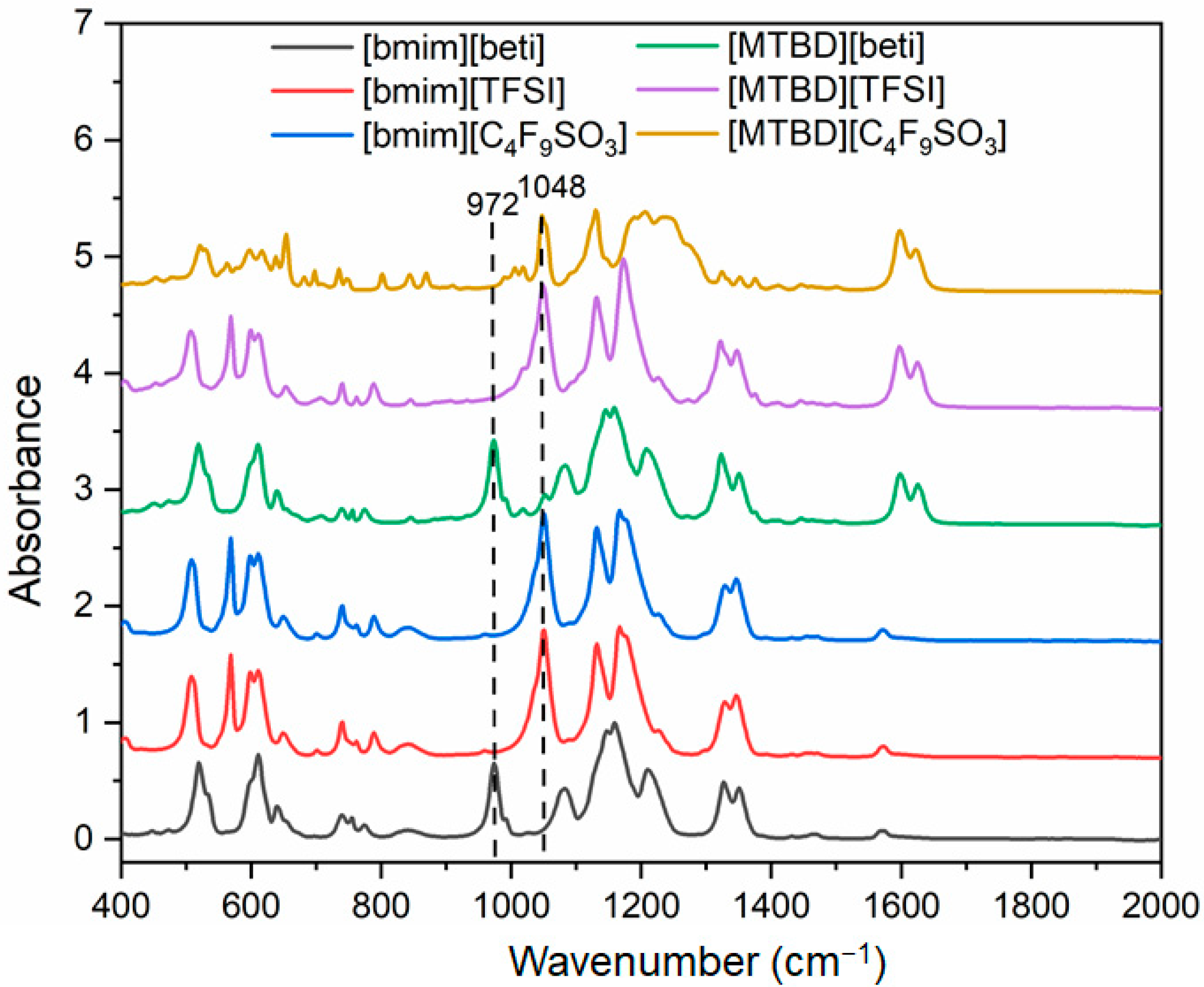
Supplementary Information for the NMR spectra). ATR-FTIR spectra of [bmim][beti], [bmim][TFSI] and [MTBD][beti] were shown in
Figure 2. The main differences, such as the –C–C–F bond in [beti]
− and the –C=C– bond in [MTBD]
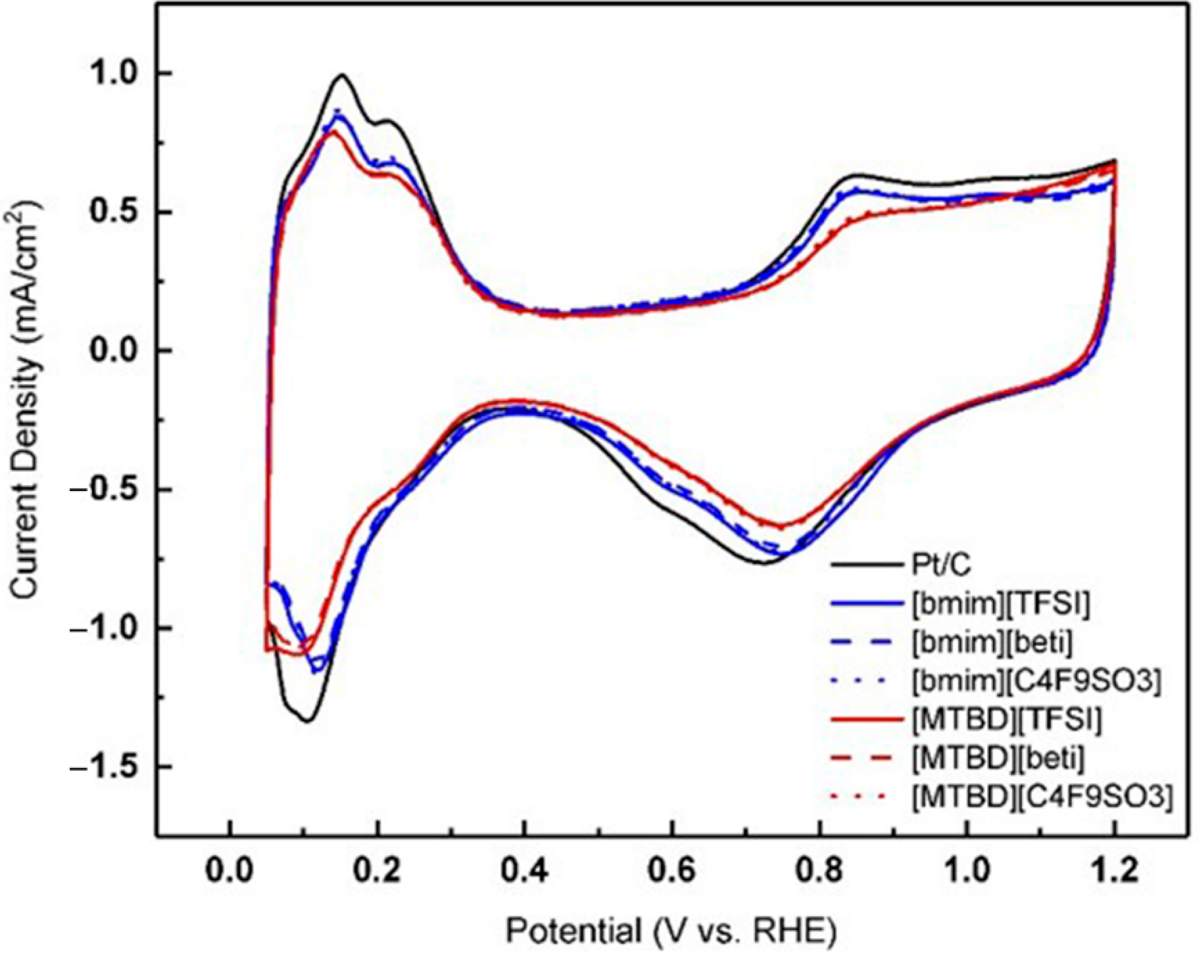
+, are indicated in the figure. The Pt/C was incorporated with various ILs and their cyclic voltammograms are shown
Figure 3. The addition of hydrophobic ILs reduced the anodic charge in the Pt oxidation region and the hydrogen adsorption charge under the H
upd region, which has been previously observed [
8,
10,
11,
12]. One interesting finding is that the hydrogen adsorption profiles of the [bmim]
+ series are identical, but smaller than that of the [MTBD]
+ series. It seems that the cation imposes more influence on the amount of hydrogen adsorption than the anion. There are several hypotheses regarding the decrease of ECA(H
upd). Arras et al. [
21] studied the hydrogen adsorption on ionic liquid coated palladium (Pd) particles and found that the anion structure affects the hydrogen uptake very much. It is suggested that the anion interacts with the Pd and changes the accessibility of Pd sites for the following hydrogen adsorption. To the contrary, our results (
Figure 3) showed that the anion structure did not change the ECA(H
upd) very much. For instance, the three [bmim]
+ ILs exhibited virtually identical hydrogen adsorption behaviors. Another hypothesis proposed is that IL molecules prevent hydrogen adsorption by occupying certain of the metal facets [
7]. In
Figure 3, hydrogen shows a sharp adsorption on Pt(110) in the perchloric acid [
22]. After incorporating [bmim]
+ ILs, the signature hydrogen adsorption peaks remained, only with reduced areas. In contrast, the adsorption peak became broader and less shaped after the incorporation of [MTBD]
+ ILs. It is speculated that [MTBD]
+ ILs may inhibit the hydrogen adsorption on Pt(110), presumably owing to a stronger bond of [MTBD]
+ on Pt than [bmim]
+.
To further elucidate the mechanism of the decrease of ECA(H
upd) and investigate how the ILs alter the hydrogen adsorption, a CO stripping measurement was conducted as an alternative approach to estimate the accessible Pt sites.
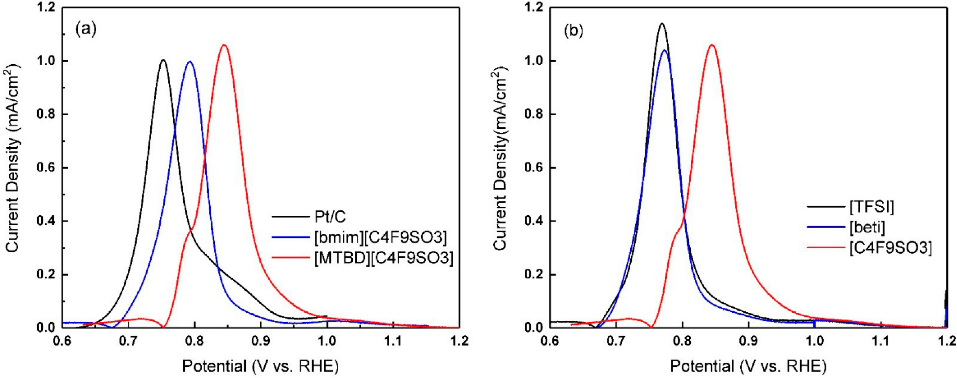
Figure 4a displays an example of CO stripping voltammetry of Pt/C-ILs, which showed identical oxidation profiles to Pt/C, but with a positive shift of the main peak position. More discussion regarding the peak shift and its effect on the ORR activity will be detailed subsequently. The charge under the CO oxidation peak was used to calculate the ECA(
CO).
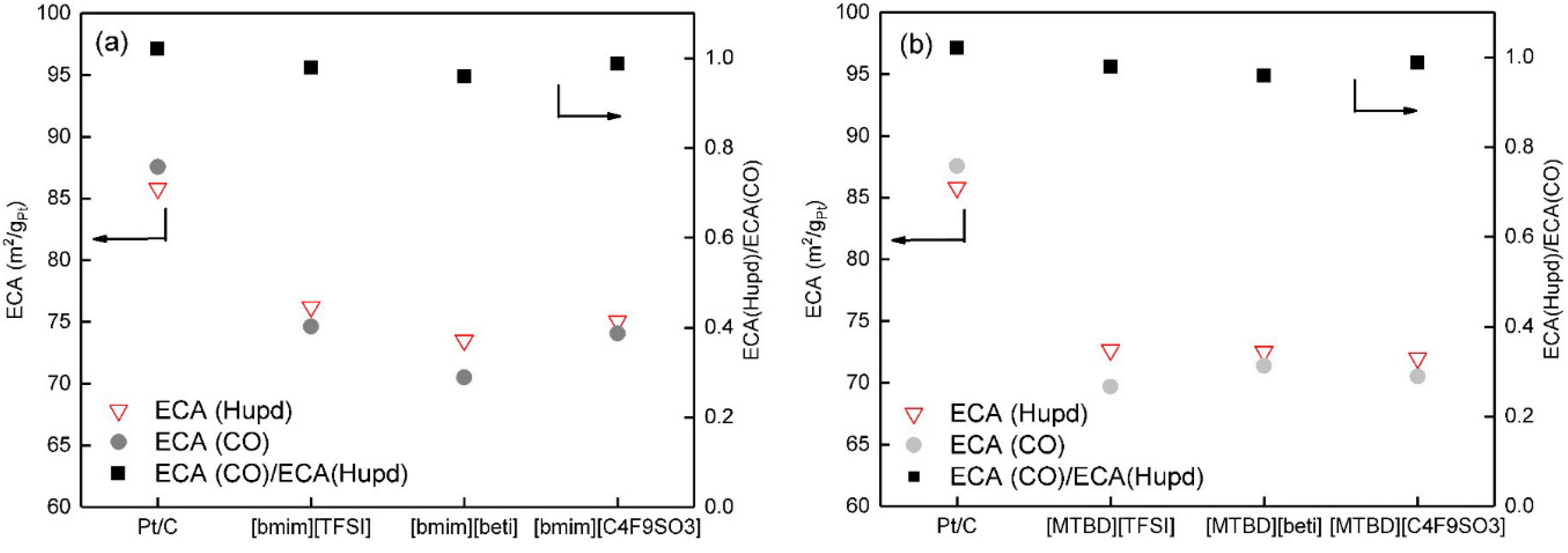
Figure 5a,b display the comparison of ECA(
CO) and ECA(H
upd) with incorporation of [bmim]
+ and [MTBD]
+ ILs, respectively. Compared to Pt/C, Pt/C-ILs both showed smaller ECA(
CO) and ECA(H
upd). Meanwhile, the ratios of ECA(
CO)/ECA(H
upd) of Pt/C-ILs were close to 1. Since the measurements of ECA(
CO) and ECA(H
upd) assumed that adsorbed CO and hydrogen forms a monolayer on the Pt surface, it is reasonable to deduce that the decrease of ECA(
CO) and ECA(H
upd) may follow a similar mechanism. Arras et al. [
21,
23] studied the CO and H
2 uptake in an IL coated palladium composite. It was found that IL coating significantly decreased the CO and H
2 uptake, which was attributed to the low gas solubilities in IL and the competitive adsorption of gas molecules and IL ions. Here, we propose two possible mechanisms that may result in the decrease of ECA: (1) IL partially covers the Pt surface and reduces the direct exposure of active sites for the adsorption; and (2) the competing adsorption of IL ions and CO/hydrogen restricts their full adsorption on the IL covered Pt surface.
Feliu et al. [
24,
25,
26,
27] developed an electrochemical method using CO as a probe molecule to study the ion adsorption on the Pt surface. The technique later evolved to be called “CO-displacement” and was adopted to semi-quantify ion coverage such as ionomer sulfonate ion (–SO
3H) coverage [
15]. Basically, CO displaces the initially adsorbed species from Pt at a given potential and cation or anion is released from the Pt surface, inducing an oxidative or reductive current, respectively. The choice of potential is critical, because it determines which species are displaced. In general, at potentials lower than 0.3 V, the primary displaced species are the adsorbed hydrogen (cation). To displace the anion species, the potential is usually held at 0.4 V or 0.5 V [
15]. In a supporting electrolyte (e.g., 0.1 M HClO
4), the hydrogen adsorption accounts for the majority of cation displacement charge, making the separation of the displacement charge of IL cation and atomic hydrogen very challenging. Our previous study showed that IL forms a thin layer on Pt and restricts the anion adsorption (e.g., (bi)sulfate, SO
42−), resulting in a smaller displacement charge [
12]. Therefore, CO displacement was conducted in the region where anion adsorption is dominant, and the displacement charge was used to examine the interaction between ILs and Pt.
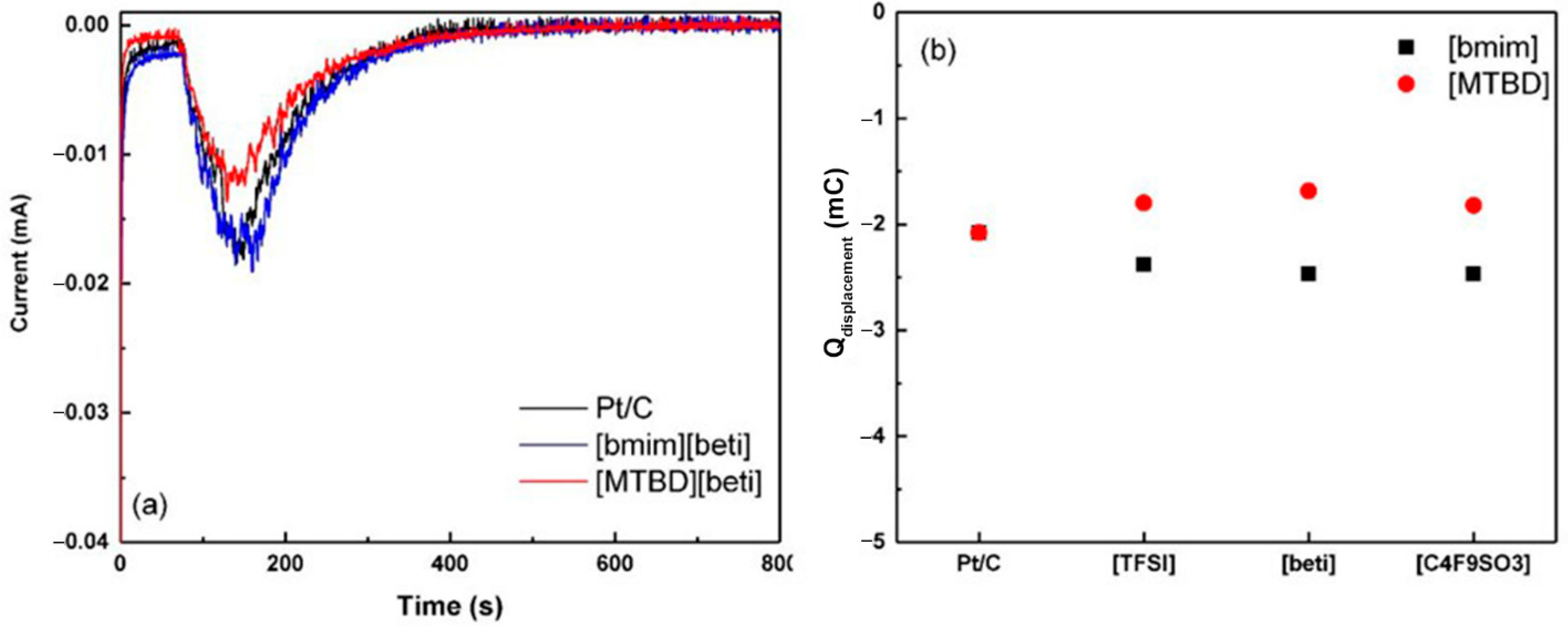
Figure 6a displays the current responses after introduction of the CO gas. The negative current indicated that the released species were adsorbed anions and the integrated charge was the total amount of initially adsorbed anions. For Pt/C, the negative displacement charge is induced by the release of ionomer (–SO
3H) and adsorbed perchlorate ion (ClO
4−), although perchlorate ion is thought to be non-adsorbing [
15,
28]. In the case of Pt/C-[MTBD][beti], the displacement charge is much smaller than Pt/C, suggesting less initially adsorbed anions on the surface. Although it is very challenging to distinguish the displacement charge of [beti]
− from the perchlorate ion and ionomer, it is reasonable to deduce that the reduced displacement charge of Pt/C-[MTBD][beti] is due to less direct contact with the electrolyte or ionomer, or the mixture of both. The adsorption of [beti]
− cannot be precluded. The anion species that can be displaced and the corresponding displacement charge depend on the selected potential. At potentials of 0.4 V and 0.5 V, the displacement charges of Pt/C were measured to be −2.11 mA·s and −2.08 mA∙s, suggesting that the adsorption of perchlorate ion and ionomer (-SO
3H) has saturated on the Pt surface at 0.4 V. In contrast, the displacement charges of Pt/C-[MTBD][beti] were −1.31 mA∙s at 0.4 V and −1.69 mA∙s at 0.5 V. This indicates that higher potential drives additional adsorption of anions, presumably originating from the [beti]
− in [MTBD][beti]. As a result, the displaced anions of Pt/C-[MTBD][beti] are consisted of ClO
4−, (–SO
3H), and [beti]
−. Unlike [MTBD][beti], Pt/C-[bmim][beti] exhibited a slightly higher displacement charge than Pt/C. Results shown in
Figure 6a,b have evidenced the presence of [bmim][beti]. Therefore, it is assumed that the substantial adsorption of [beti]
− outnumbered the reduced adsorption of perchlorate ion and ionomer, resulting in an increase of displacement charge. The lower displacement charge of Pt/C-[MTBD][beti] than Pt/C-[bmim][beti] indicates that [MTBD][beti] may have stronger interaction with Pt and restricts more anion adsorption, such as ClO
4− and (–SO
3H).
The CO displacement for Pt/C with the full series of [bmim]
+ and [MTBD]
+ ILs were further measured, and the results are presented in
Figure 4b. All three systems with [MTBD]
+ ILs had virtually identical displacement charges. Similarly, the [bmim]
+ series also showed identical displacement charges, but the values were higher than [MTBD]
+ ILs. This suggests that the cation imposes a higher impact on the interaction with Pt than the anion and [MTBD]
+ shows stronger interaction strength than [bmim]
+. The results along with the CV studies lead one to conclude that: The decrease of ECA(H
upd) and ECA(
CO) is due to IL covering Pt that restricts the direct adsorption of CO/hydrogen, and the cation structure affects the amount of CO/hydrogen adsorption through a competitive adsorption mechanism.
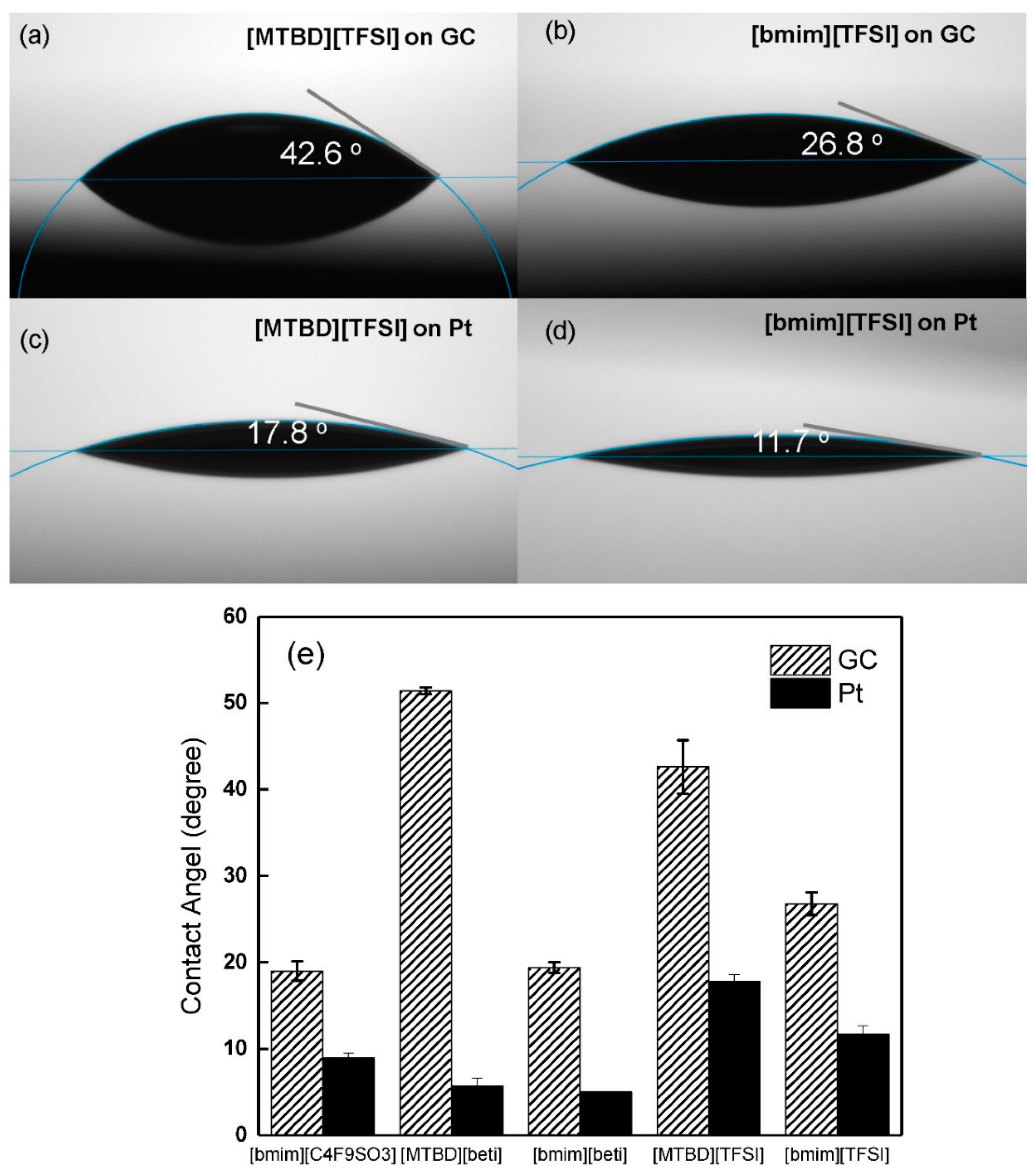
The study described above suggests the ILs with varied structures may interact with the catalyst differently. Therefore, contact angle measurements of ILs were carried out on a glassy carbon (GC) and a flat platinum film to study their affinities for the substrates. Examples of contact angles of [MTBD][TFSI] and [bmim][TFSI] on GC and Pt film are shown in
Figure 7a–d. The contact angles of [MTBD][TFSI] are larger than that of [bmim][TFSI] on both GC and Pt film, suggesting a higher surface tension of [MTBD][TFSI]. The measurements were also conducted on the rest of ILs except for [MTBD][C
4F
9SO
3], which is a solid at room temperature. The results were summarized in
Figure 7e. The [bmim]
+ ILs have virtually identical contact angles on GC, and they are smaller than the [MBTD]
+ ILs series. A similar trend of contact angles was also found on the Pt surface. Although the surface properties of GC and Pt film tested here are different from the Pt/C used for electrochemical measurements, which possesses high surface roughness, the contact angle measurements still provide indirect evidence towards the interaction between IL and catalyst. The results showed that the cation affected the interaction more than the anion, which is consistent with the findings in the electrochemical studies.
The formation of OH
ads on Pt through Pt + H
2O→Pt-OH
ads + H
+ + e
− is known to block the metallic Pt site and imposes a negative electronic effect on the ORR kinetics [
29,
30]. In the process of CO stripping, the reaction between adsorbed CO
ads and the adjacent formed OH
ads (CO + OH
ads→CO
2 + H
+ + e
−) is generally considered to be the rate determining step [
17,
18]. With the aid of CO, it is possible to probe the effect of IL on the Pt-OH
ads formation. Representative CO stripping voltammograms for Pt/C and Pt/C-ILs are presented in
Figure 4a. Compared to Pt/C, the main CO oxidation peak of Pt/C-ILs shifts towards a higher potential, indicating a delay of CO oxidation reaction caused by less OH
ads formation. Furthermore, the oxidation peak potential of [MTBD][C
4F
9SO
3] is higher than that of [bmim][C
4F
9SO
3]. It is presumed that the total amount of OH
ads formed on Pt/C-[MTBD][C
4F
9SO
3] was less than [bmim][C
4F
9SO
3]. Measurements were further extended to study the rest of the ILs, and an example of the [MTBD]
+ ILs series is presented in
Figure 4b. The peak potentials varied with the anion, and followed an order of [TFSI]
− ≈ [beti]
− < [C
4F
9SO
3]
−. It is speculated that [C
4F
9SO
3]
− restricts OH
ads formation the most, presumably owing to its long hydrophobic fluoroalkyl chain.
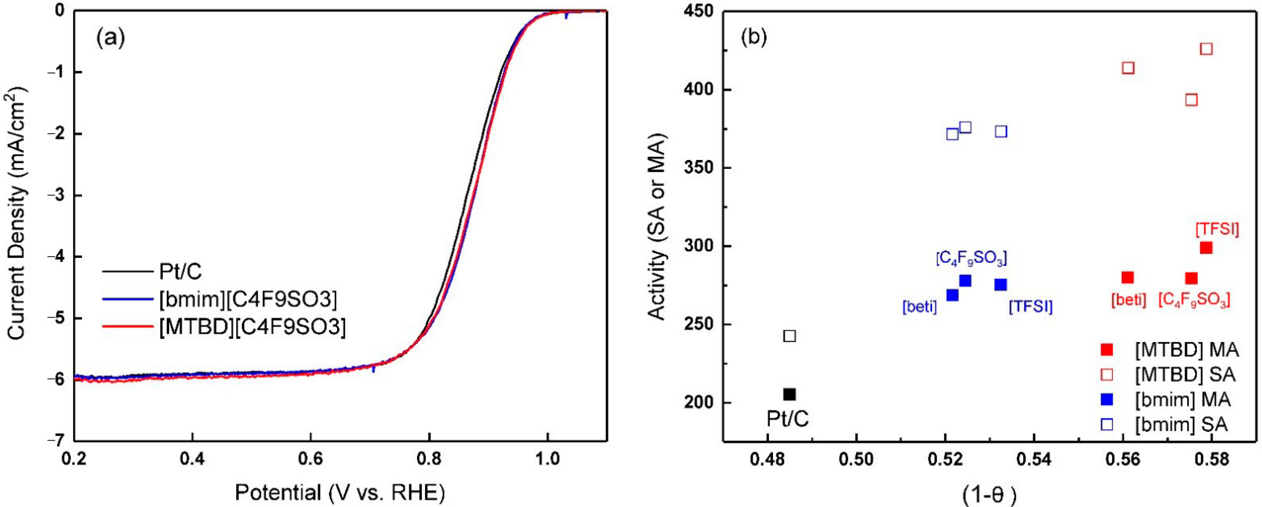
Representative ORR polarization curves of Pt/C-ILs are displayed in
Figure 8a. Compared to Pt/C, the half wave potential of Pt/C-ILs were positively shifted by ~10 mV, reflecting enhanced ORR activities. A ~36% increase in the mass activity was achieved at 0.9 V. However, the difference of apparent current is small when comparing [MTBD][C
4F
9SO
3] to [bmim][C
4F
9SO
3]. Conway et al. [
31] proposed that after Pt-OH
ads is initially formed, it will be subject to a “place-exchange” process, and finally inserted under the metal skin. Only the most recently formed Pt-OH
ads stays on the top of the Pt surface, and only this Pt-OH
ads is reversible, accounting for about 10% of the total surface oxygenated species. Moreover, chemisorbed O
ads instead of OH
ads is formed between 0.85 V and 1.15 V [
32]. The CO stripping may only react with the reversible OH
ads on the top of Pt, but not the other oxygenated species within the Pt lattice.
The generally accepted kinetic ORR current expression form follows the equation [
11,
33]
where the term (1 −
θ) is the availability of metallic Pt. Here, we used the anodic charge as total amount of formed oxides to assess
θ (
θ is a ratio of anodic charge builds at 0.9 V to the charge under H
upd region
) [
12]. The individual values of (1 −
θ) of [MTBD]
+ ILs were close to each other, but higher than [bmim]
+ ILs, as shown in
Figure 8b.
Our previous studies reported that although the oxygen solubility in ILs is several fold higher than in the aqueous electrolyte, its effect on the specific ORR activity (SA) is small [
12]. On the other hand, SA of Pt/C-ILs showed a dependence on (1 −
θ).
Figure 8b plots the ORR activities against (1 −
θ). The results showed that the individual SA of Pt/C with the [MTBD]
+ ILs is identical but higher than those of Pt/C with [bmim]
+ ILs, following a similar trend of (1 −
θ). Therefore, we propose that although the anion structure affects the reversible Pt-OH
ads formation, the eventual intrinsic activity is largely dependent on the availability of oxides-free Pt. The mass activity (MA) is a product of specific activity and electrochemical surface area. The smaller SA of Pt/C with [bmim]
+ ILs is compensated by the larger ECA, yielding identical mass activities of Pt/C with [MTBD]
+ ILs.
Besides the OH
ads formation, the IL anion adsorption on Pt was also reported to reduce the ORR activity [
22,
30]. Munakata et al. used in-situ FT-IR spectroscopy to study the anion adsorption phenomena in the pure IL electrolytes [
34]. The results showed that [TFSI]
− strongly adsorbed on the Pt surface through the –SO
2-N group, while bulkier [beti]
− exhibited a much weaker adsorption due to its extended fluoroalkyl chain. As a result, [TFSI]
− exhibits a higher overpotential than [beti]
−. Ejigu et al. also reported that the adsorption of [TFSI]
− significantly decreased the ORR activity [
35]. Regarding the adsorption of [C
4F
9SO
3]
−, our previous results showed that it has a weak interaction with Pt and did not affect the ORR activity and ECA [
12]. All those studies used a polycrystalline Pt disk immersed in the IL electrolytes. However, for the Pt-ILs studied here, Pt was exposed to abundant aqueous electrolyte, ionomer (–SO
3H), and ILs. Although CO displacement study has evidenced the adsorption of IL anion on Pt, based on the experimental results, it is assumed that the effect of IL anions adsorption on the ORR activity is small.
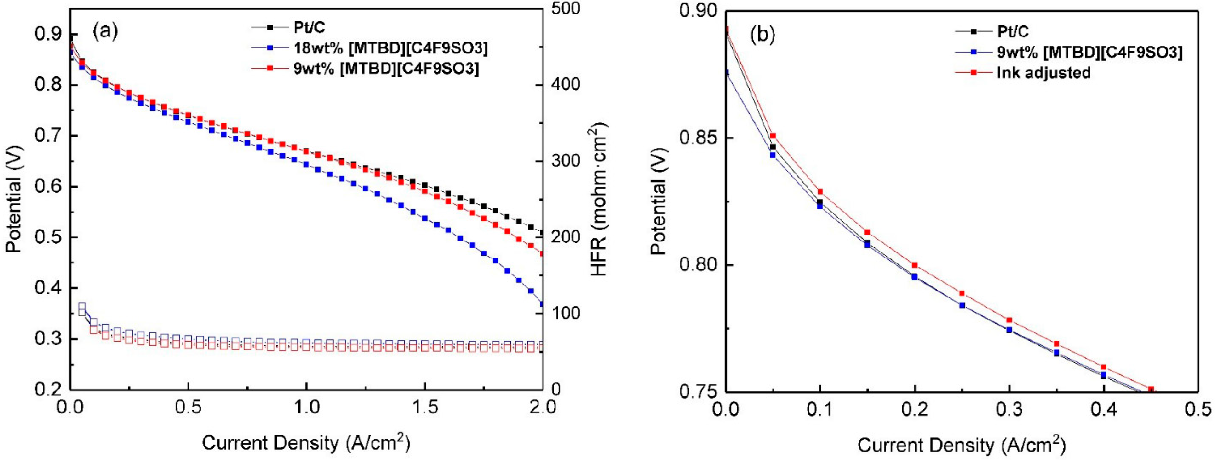
[MTBD][C
4F
9SO
s] was selected for further study in the MEA. The polarization curves for Pt/C and Pt/C-[MTBD][C
4F
9SO
3] were shown in
Figure 9a. Compared to Pt/C, the addition of 18wt.% [MTBD][C
4F
9SO
3] reduced the overall
I-V performance. Moreover, a significant potential drop in the high current density region was found, where oxygen transport plays a dominant role. The high current performance is strongly dependent on the electrode roughness factor (cm
2Pt/cm
2electrode) [
36], and it is believed that the decreased ECA of Pt/C-[MTBD][C
4F
9SO
3] is one of the major causes for the performance loss. In addition, the relatively high IL loading (18 wt.% IL) in the catalyst layer may block the pores of electrode, resulting in the increase of oxygen transport resistance.
The RDE measurements of Pt/C-ILs were conducted in fully flooded environment, where ILs experienced substantial leaching at the initial step [
12]. As a result, the final IL on the catalyst surface was undoubtedly much lower than the initial value and the ORR activity enhancement solely benefited from the remaining IL. When the operation of the MEA was not in a fully flooded condition, the leaching of IL is expected to be slower than in the aqueous electrolyte. As a result, the excess of IL was responsible for the performance loss. Reducing the IL loading in half (9 wt.% IL), the performance loss in the kinetic region was largely recovered, but still inferior to Pt/C. The ORR activity improvement demonstrated in the RDE was not successfully translated into MEA. It is important to point out that IL would re-dissolve into the alcohol during the ink preparation and ORR activity improvement in the RDE was not achieved in an alcohol rich ink formula (not shown here). Therefore, in this work, we adopted a water rich ink for the RDE measurement (water to IPA volume ratio: 4/2.25). For the MEA ink slurry formulation, the water/alcohol weight ratio was set at 0.84, which may re-dissolve some of the IL. Moreover, the aggressive and extensive agitation further accelerates the IL re-dissolution, leading to a random distribution of IL in the final electrode. As a countermeasure, the water/alcohol weight ratio was adjusted to 1.33 and the MEA performance in the kinetic region was improved, as shown in
Figure 9b. The finding suggests that the ink formula is critical and is worthy of further studies.
The potential loss in the high current region was not fully recovered even after adjusting IL loading and ink formula, and it leads us to consider the effect of catalyst properties such as carbon support. The carbon structures are important for the electrode design and they affect the MEA performance [
37]. Therefore, in addition to the Pt/Vulcan used in this study, we also studied Pt on Ketjen black (47 wt.% Pt, TKK TEC10E50E). Different from Pt/Vulcan, which uses a solid carbon and has low surface area (~250 m
2/g), Pt/Ketjen features a porous structure and high surface area (~800 m
2/g). The same MEA preparation process and measurements were applied to TKK Pt/C and TKK Pt/C-[MTBD][C
4F
9SO
3], and the IL to carbon weight ratio (IL/C) was set at 0.1, the same as Pt/Vulcan-[MTBD][C
4F
9SO
3] (9 wt.% IL or IL/C = 0.1). The ink for TKK Pt/C-[MTBD][C
4F
9SO
3] was also formulated to be water rich with a water/alcohol weight ratio of 1.26. The two cathode materials exhibited identical CV profiles in the potential range, and ECAs of Pt/C-[MTBD][C
4F
9SO
3] and Pt/C were measured to be 47.3 m
2/g
Pt and 48.7 m
2/g
Pt, as shown in
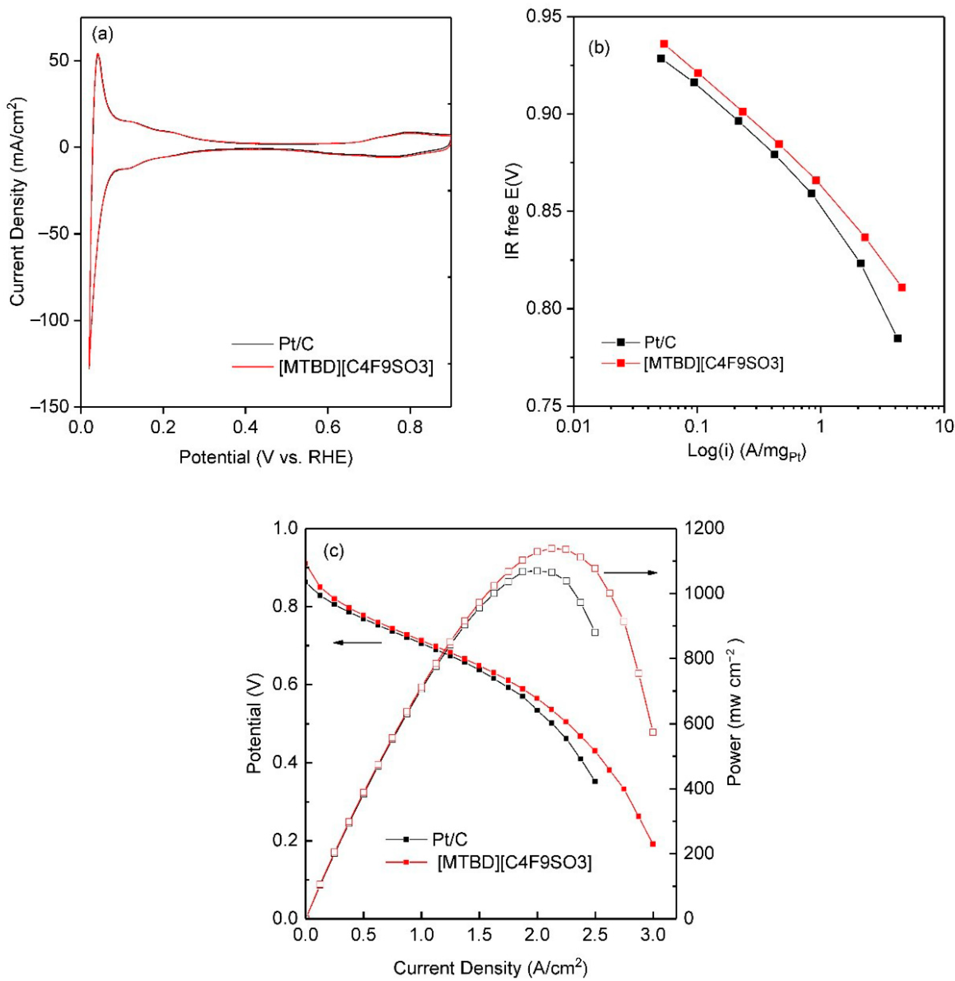
Figure 10a. It is speculated that the high surface of TKK Pt/C reduces the thickness of the IL layer compared to Pt/Vulcan at the same IL/C ratio, resulting in a minimal ECA loss. Meanwhile, IL reduced the oxides coverage of Pt/C from
θ = 0.74 to
θ = 0.67 of Pt/C-[MTBD][C
4F
9SO
3], agreeing with the CV findings in the RDE. The polarization performances of the two cathode materials were further assessed in pure O
2 to study the effect of IL on the ORR kinetics. As shown in
Figure 10b, Pt/C-[MTBD][C
4F
9SO
3] exhibited a higher performance than Pt/C, and the ORR activities at 0.9 V were calculated to be 242 mA/mg
Pt and 179 mA/mg
Pt, respectively. Less oxide formation on Pt/C-IL was assumed to be one of the reasons for the activity improvement. Besides, the possibility that IL increases O
2 collision frequency and deceases anion adsorption cannot be excluded and needs further investigation. The polarization curves in air were also measured and are shown in
Figure 10c. Compared to Pt/C, Pt/C-[MTBD][C
4F
9SO
3] exhibited a considerable performance increase throughout the current density range. The higher potential of Pt/C-[MTBD][C
4F
9SO
3] than Pt/C in the kinetic region can be attributed to the enhanced ORR activity. More importantly, the performance of Pt/C-[MTBD][C
4F
9SO
3] in the high current density region was greatly improved, which is believed to be associated with facilitated oxygen transport within the electrode. In general, the oxygen transport resistance in the electrode mainly consists of the molecular diffusion resistance in the pores and the transport resistance at the interface between the ionomer and Pt [
38,
39,
40,
41]. It is likely that IL reduced the oxygen transport resistance by homogenously distributing the ionomer in the electrode [
42,
43] or increasing the oxygen permeability at the interface of Pt and ionomer [
40]. In addition, the hydrophobic IL may limit the product water build up that hinders the mass transport of O
2 [
10]. The experimental measurements of O
2 transport resistance using an internally established method [
38,
39] are ongoing to explore the mechanism.
The MEA results reported here are far from optimized and a deeper understanding is needed to address many unknowns. More studies are underway in our laboratory including electrode engineering and we will report them in the near future. Fortunately, this study successfully demonstrated the feasibility of the application of IL to enhance the MEA performance, which may serve as a complementary solution to improve the PEMFC performance, in addition to the development of novel catalysts.
3. Experimental
Reagents. For IL synthesis, HNO3 (70%), lithium bis((trifluoromethyl)sulfonyl) amide (99.95%), 1-butyl-3-methylimidazolium bromide, potassium nonafluorobutane sulfonate (98%) and MTBD (98%) were purchased from Sigma Aldrich (St. Louis, MO, USA). Lithium bis((perfluoroethyl)sulfonyl)amide (99%) was purchased from Iolitec (Tuscaloosa, AL, USA). For electrochemical evaluation, Johnson Matthey Pt/C catalyst (20 wt.%, Hispec 3000, Vulcan carbon as the support) was purchased from The Fuel Cell Store (College Station, TX, USA)and used as the ORR catalyst platform for most of the RDE and MEA investigations. An additional Pt/C catalyst (TKK TEC-10E50E, Ketjen black as the support) was purchased from TANAKA Kikinzoku International (America), Inc. (Chicago, IL, USA) for the MEA study. HClO4 (70%, GFS Chemicals (Powell, OH, USA)), isopropanol (99.5%, Sigma Aldrich (St. Louis, MO, USA)), ethanol (≥99.5%, Sigma Aldrich), propylene glycol (99.5%, Sigma Aldrich), Nafion dispersion (DE520 and D2020, Ion Power (New Castle, DE, USA)), and Nafion membrane (NR211, Ion Power) were used as received.
Synthesis of ILs: 7-methyl-1,5,7-triazabicyclo[4.4.0]dec-5-ene bis(perfluoroethylsulfonyl)amide ([MTBD] [beti]): A solution of MTBD (2.51 g, 0.0164 mol) in water (100 mL) was cooled down to 0 °C and nitric acid (1.47 g, 0.0164 mol) was added dropwise to the solution, followed by the addition of lithium bis(perfluoroethylsulfonyl)amide (6.34 g, 0.0164 mol). The mixture was stirred for 1 h and the IL was separated from the mixture as a viscous fluid phase beneath the aqueous phase. The resulting IL was washed 4 times with ultrapure water and dried under reduced pressure on a rotary evaporator at 50 °C for 18 h to obtain a colorless liquid.
Similar synthesis routes and purification processes were used to prepare the rest of the ILs:
7-methyl-1,5,7-triazabicyclo[4.4.0]dec-5-ene bis(trifluoromethylsulfonyl)amide ([MTBD][TFSI]).—The chemicals used to prepare [MTBD][TFSI] were: MTBD (2.25 g, 0.0146 mol), nitric acid (1.32 g, 0.0146 mol), and lithium bis((trifluoro- methyl)sulfonyl)amide (4.22 g, 0.0146 mol).
7-methyl-1,5,7-triazabicyclo[4.4.0]dec-5-ene 1,1,2,2,3,3,4,4,4-nonafluorobutane-1-sulfonate ([MTBD][C4F9SO3]).—The chemicals used to prepare [MTBD][C4F9SO3] were: MTBD (3.00 g, 0.0196 mol), nitric acid (1.76 g, 0.0196 mol) and potassium nonafluorobutane sulfonate (8.58 g, 0.0196 mol).
1-butyl-3-methylimidazolium bis(perfluoroethylsulfonyl)amide ([bmim][beti]).—The chemicals used to prepare [bmim][beti] were [bmim][Br] (3.50 g, 0.0159 mol) and lithium bis((perfluoroethyl)sulfonyl)amide (6.18 g, 0.0159 mol).
1-butyl-3-methylimidazolium bis(trifluoromethylsulfonyl)amide ([bmim][TFSI]).—The chemicals used to prepare [bmim][TFSI] were: [bmim][Br] (3.5 g, 0.0159 mol) and lithium bis(trifluoro- methylsulfonyl)amide (4.59 g, 0.0159 mol).
1-butyl-3-methylimidazolium 1,1,2,2,3,3,4,4,4-nonafluorobutane-1-sulfonate ([bmim] [C4F9SO3]).—The chemicals used to prepare [bmim][C4F9SO3] were: [bmim][Br] (3.00 g, 0.0136 mol) and potassium nonafluorobutane sulfonate (4.63 g, 0.0136 mol).
ATR-FTIR measurements. ATR-FTIR spectra of synthesized ionic liquid were recorded using a Thermo Scientific Nicolet™ iS20 FTIR (Thermo Fisher Scientific, Waltham, MA, USA) Spectrometer in the range 400–4000 cm−1.
Contact angle measurements: The contact angles of ILs on Pt film and carbon surfaces were measured with a Drop Shape Analyzer DSA100S (KRÜSS Scientific Instruments, Inc., Matthews, NC, USA). Platinum was deposited on a wafer by sputter coating (Intlvac, Fort Collions, CO, USA) with a thickness of 250 nm. A glassy carbon plate (25 × 25 mm, type 2) was purchased from Alfa Aesar (Tewksbury, MA, USA) and used as received without further polishing. The substrates were washed sequentially with isopropanol and deionized water in an ultrasonic bath for 30 min and dried in air. An environmental chamber TC11 (KRÜSS Scientific Instruments, Inc., Matthews, NC, USA) was saturated with dry nitrogen and the temperature was controlled at 20 ± 0.1 °C A 1 μL sample of IL was dispensed onto the substrate surface and equilibrated for 10 min until the contact angle no longer changed. Then a final measurement was taken to record the contact angel. Five independent measurements were taken for each IL on each substrate and the average of the measurements was obtained. The overall uncertainties for contact angles are the standard deviations calculated from the data for five independent drops. The solid substrates were scanned using an Asylum MFP-3D atomic force microscope (AFM) (Oxford Instruments NanoAnalysis & Asylum Research, High Wycombe, UK) on three random locations using 50 µm × 50 µm scan sizes. The roughness was analyzed with the internal software provided by Asylum Research for calculating the root mean square (RMS) and arithmetic average (Ra). The roughness of the glassy carbon is 0.88 nm (RMS) and 0.48 nm (Ra). The roughness of the platinum is 1.93 nm (RMS) and 1.46 nm (Ra).
ORR activity measurements. All electrochemical measurements were performed on an EC-LAB SP-300 (BioLogic Science Instruments, Knoxville, TN) and the electrolytes were prepared with Millipore (Milli-Q Synthesis, Millopore Sigma, Burlington, MA) water with a resistance greater than 18.2 MΩ·cm. A Pt wire (Pine Research Instrumentation, Inc. (Durham, NC), AFCTR5) and a hydrogen reference electrode (Hydroflex, eDAQ) were used as counter electrode and reference electrode, respectively. All potentials in this work are reported against a reversible hydrogen electrode (RHE) unless specified otherwise.
The details of preparation of IL impregnated Pt/C (Pt/C-ILs) can be found in our previous publication [
12]. Here, the IL loading was controlled at 18 wt.%, much lower than the previous study. The Pt/C-IL was dispersed in a solution containing 4 mL DI water, 2.25 mL isopropanol and 25 uL Nafion dispersion (DE520) and the ink was subject to 15 min ultrasonication in an ice bath. A 10 uL aliquot of this ink was pipetted onto the glassy carbon (GC) disk (5 mm diameter, Pine Instrument) and rotationally dried in air to form a uniform catalyst layer [
44]. The calculated final Pt loading on the disk is 16.2 ug/cm
2disk. The control sample of Pt/C without IL was prepared in the exact same way as the Pt/C-IL samples.
The catalyst coated GC was first pre-conditioned in N
2-saturated 0.1 M HClO
4. Typically, the working disk was scanned from 0.05 V to 1.2 V with a scan rate of 100 mV·s
−1 until the cyclic voltammetry (CV) curve did not change. After that, a stable CV was recorded from 0.05 to 1.2 V at 50 mV·s
−1. ECA
(Hupd) was obtained by integrating the charge under the hydrogen adsorption region (H
upd). ORR measurements were conducted in the saturated 0.1 M HClO
4 and multiple independent data sets were collected. All the intrinsic activities were corrected with N
2-background and IR compensation [
12].
CO measurements. CO stripping experiment was carried out to estimate the ECA
(CO) of Pt/C-ILs, which was compared with ECA
(Hupd). In general, CO (2% carbon monoxide in argon, Airgas) was introduced into N
2 pre-saturated 0.1 M HClO
4 while holding the electrode potential at 0.1 V for 15 min to complete the CO adsorption on the Pt surface. Then the electrolyte was purged with N
2 for 20 min to remove the CO while maintaining the electrode potential at 0.1 V. The adsorbed monolayer of CO on the Pt surface was then stripped off by sweeping the electrode from 0.1 V to 1.2 V for 3 cycles at a scan rate of 20 mV·s
−1. The second cycle was used as baseline for the CO stripping peak in the first cycle and the charge under the peak was integrated for the ECA
(CO) calculation, assuming a specific charge of 420 uC cm
Pt−2 for a monolayer of adsorbed CO [
16].
CO displacement characterization was employed to investigate the effect of IL structure on the surface coverage in the Pt/C-ILs. Typically, the catalyst coated electrode was immersed in N
2-saturated 0.1 M HClO
4 and conditioned by cycling 80 times from 0.05 to 1.2 V. Then the electrode was held at a desired potential (e.g., 0.5 V) and the N
2 valve was switched to CO gas. A displacement current was recorded until a new baseline was established and the charge under the curve was integrated as the displacement charge of either anion or cation adsorbed on the Pt surface [
15].
MEA preparation. The Pt/C-[MTBD][C
4F
9SO
3] was selected as cathode material for the MEA evaluation, and compared with Pt/C. The catalyst ink consisted of ethanol, propylene glycol, water, Nafion ionomer (D2020), and catalyst. The ionomer to carbon (I/C) weight ratio and the solid content were kept at 0.9 and 14 wt.%, respectively. The ink slurry was vigorously mixed and coated on a poly (tetrafluoro-ethylene) substrate (0.002” thick, Macmaster-CARR) using a doctor-blade casting method. Similarly, a Pt/C (30 wt.% Pt/C, TEC10EA30E, TKK) catalyst layer with I/C ratio at 1.07 was prepared as the anode material. The coating layer was dried at 80 °C to remove the solvent. The final anode and cathode Pt loading were controlled at 0.05 and 0.16 mg
Pt/cm
2, respectively. Two pieces of square electrocatalyst layer (2 cm × 2 cm) of cathode and anode were punched and sandwiched between a Nafion 211 membrane to form a catalyst coated membrane (CCM) using a decal-transfer technique [
45]. The hot-pressing condition was set at 130 °C and 0.8 MPa for 5 min. The gas diffusion layers (29 BC, SGL Carbon (Charlotte, NC)) together with the CCM were assembled in a single cell with a serpentine flow field (Scribner Associates, Southern Pines, NC, USA).
MEA measurements: A 850e Fuel Cell test system (Scribner Associates) was used for the MEA performance evaluation. The MEA was first activated by sweeping between 0.9 V and 0.1 V for several hundred cycles under H2/Air (0.5 NLPM/1 NLPM) at 45 °C and relative humidity (RH) of 100%. Then the i-V performance of the MEAs were measured at 70 °C under 100% RH. Ultrapure H2 and Air were supplied to the anode and cathode with a gauge pressure of 150 kPa. The current density was set with an incremental of 0.05 A/cm2 and the response voltage was recorded simultaneously. The high frequency resistance (HFR) was also recorded throughout the measurement.


 ,
, 


