Article

Development of Pilot-Scale CO2 Methanation Using Pellet-Type Catalysts for CO2 Recycling in Sewage Treatment Plants and Its Validation through Computational Fluid Dynamics (CFD) Modeling

1
Department of Environmental Energy Engineering, Graduate School of Kyonggi University, 94 San, Iui-dong, Youngtong-ku, Suwon-si 16227, Korea
2
Department of Environmental Engineering, Chungnam National University, 99, Daehak-ro, Yuseong-gu, Daejeon 34134, Korea
3
Fivetek company, 177 Kumgang High Tech Valley, Sagimakgol-ro, Jungwon-gu, Seongnam-si 13217, Korea
4
Department of Environmental Energy Engineering, College of Creative Engineering, Kyonggi University, 94 San, Iui-dong, Youngtong-gu, Suwon-si 16227, Korea
*
Authors to whom correspondence should be addressed.
Catalysts 2021, 11(8), 1005; https://doi.org/10.3390/catal11081005
Submission received: 18 July 2021 / Revised: 16 August 2021 / Accepted: 19 August 2021 / Published: 20 August 2021

Abstract

:
In this study, a pilot-scale reactor was designed and compared using computational fluid dynamics (CFD) for a high-efficiency CO2 methanation reaction. The trends of the CO2 methanation catalyst efficiency at a pilot or industrial scale could be lower than those measured at the laboratory scale, owing to the flow of fluid characteristics. Therefore, the CO2 methanation reactor was designed based on the results of the CFD analysis to minimize the above phenomenon. Ni–Ce–Zr was used to manufacture a CO2 methanation catalyst in the form of pellets. The catalyst successfully produced about 43.3 Nm3/d of methane from the reactor. This result shows that CO2 methanation, which is known as an exothermic reaction, was stable at the pilot scale. It is believed that the self-supply of energy will be possible when this CO2 methanation technology is applied to industrial processes generating large amounts of CO2 and H2 from by-product gases.

Graphical Abstract

1. Introduction

Owing to the rapid ecosystem change, abnormalities within the climatic cycle are occurring more frequently today than before. With the change in climatic conditions caused by increased global warming, rising sea levels, amplified greenhouse gases, and melting glaciers, the human race is tackling extreme social, economic, and existential crises. According to the Intergovernmental Panel on Climate Change (IPCC) report, the Earth’s average air temperature and sea level will rise by 3.7 °C and 63 cm, respectively, during the 2081–2100 period compared to the 1986–2005 period, if greenhouse gases are still emitted in the same manner or more [1]. Greenhouse gas occurs both naturally and artificially, but it is more likely to be caused by anthropogenic activity; thus, finding ways to reduce greenhouse gas emissions is challenging. The EU has set a high-level goal to curb carbon emissions by 2030 by setting the 2030 climate energy framework. Similarly, the United States of America presented the goal of reducing carbon emissions from thermal power plants by 32% by 2030 (compared to 2005), announcing the Clean Power Plan in 2015 [2]. Likewise, the world is observing a paradigm shift to cope with global climate change, with the Paris Agreement being adopted by advanced countries and subsequently by all countries in 2015. Countries around the world endeavor to build a climate-resilient system by establishing a countermeasure for greenhouse gas reduction [3].
As the urgency to reduce CO2 and other greenhouse gas emissions increases, carbon capture and utilization (CCU), which uses CO2 as a source of renewable energy, has recently received more attention. CCU is a technology that collects and utilizes CO2 directly, converting it into an energy source or fuel without separate storage. This method is advantageous in terms of resource management [4,5].
CO2 methanation converts CO2 to CH4 through a chemical reaction. 4 M H2 and 1 M CO2 produced 1 M CH4 and 2 M H2O, thus effectively converting CO2 to renewable energy. Conversely, existing infrastructure for gas that has been converted to methane by CO2 and H2 generated from industrial processes can be used while injecting the output methane gas into a natural gas network, which helps reduce the carbon footprint by eliminating the need for added construction [6]. The need for energy storage and supply technology has increased over the years, and power-to-gas (PtG) technology is a promising way to overcome this crisis. Among PtG technologies, the power to methanation (PtM) process has garnered attention as a new energy storage medium owing to its higher storage capacity and longer lifetime compared to other energy storage systems [7]. Germany is one of the countries where the PtG project is being conducted. The e-gas project from Audi supplies methane gas to existing natural gas supply lines by converting CO2 into methane. However, only a handful of cases have successfully applied CO2 methanation technology to the industrial process on a large scale.
In general, CO2 methanation is Sabatier’s reaction, which is known as an exothermic reaction when CO2 is converted to CH4. The optimum temperature range is known to be 200–550 °C, depending on the catalyst Equation (1) [8,9]:
CO2 (g) + 4H2 (g) ↔ CH4 (g) + 2H2O (g), ∆H°298K = −165 KJ·mol−1
Miao et al. assumed that Equation (1) is a two-step reaction. Mechanisms of Equations (2) and (3) are as follows:
CO2 (g) + H2 (g) ↔ CO (g) + H2O (g), ΔH°298K = 41 KJ mol−1
CO (g) + 3H2 (g) ↔ CH4 (g) + 2H2O (g), ∆H°298K = −206 KJ·mol−1
In the first step, carbon dioxide and hydrogen undergo the reverse water–gas shift (RWGS) reaction via a separation mechanism and are converted to CO and H2O. In the second step, CO reacts with H2 to generate CH4 and H2O. This implies that, if CO is not generated, the reactions in Equations (2) and (3) would have occurred consecutively [10].
In terms of thermodynamics, Sabatier’s reaction can occur at a low temperature (200 °C or lower). In contrast, due to the RWGS reaction, the CO selectivity increased at high temperatures (above 600 °C) [11]. Therefore, this reaction requires a catalyst for high conversion and reaction rates, and it can be applied to various processes as it has the advantage of being operated at a low temperature [12]. For such reactions, Vlll metallic catalysts such as Pt, Pd, Ru, Rh, and Ni are generally used; among them, Ni catalysts are widely employed because of their excellent competitive price and reaction in commercial processes, making them suitable for commercialization [13,14,15,16]. CO2 methanation catalysts are highly efficient and durable and can be used in various industrial processes. There have been many studies on catalyst types, including disks, pellets, honeycombs, and granules [17,18,19].
CO2 methanation catalysts are required to have high efficiency and durability for use in various industrial processes. Therefore, various forms of catalysts such as disks, pellets, honeycombs, and granules have been investigated in previous studies. The CO2 methanation reactor must consist of a material that can resist pressure and corrosion due to the exothermic properties of the catalytic reaction, and the heat must be easy to control. When laboratory-scale equipment has been scaled up to the pilot or commercial plant size, the catalytic performance can differ [20].
Specifically, if the flow of fluid in the reactor is not uniform, the catalyst efficiency is likely to decrease. Therefore, this study is designed to maximize the catalytic performance (theoretical maximum value) by analyzing the flow of fluid in a system and the characteristics of the reaction using computational fluid dynamics (CFD). Such CFD analyses are applied to a variety of environmental energy plant facilities as they are advantageous in achieving economic results in a relatively short time over model experiments for various factors such as the structural geometry and operating conditions [21,22].
In this study, the goal was to maximize the methane production efficiency at the pilot scale of a CO2 methanation plant and maintain its stable operation. CFD simulation was conducted according to the 2-type form of the reactor to compare the theoretical catalytic efficiency based on the flow of fluid characteristics. The reactor design that displayed maximum efficiency was selected from among them. Furthermore, we observed the actual CO2 methanation catalyst efficiency from the experiment and conducted an optimization study on the operation by establishing the CO2 methanation plant operation methods in a stepwise manner.

2. Results and Discussion

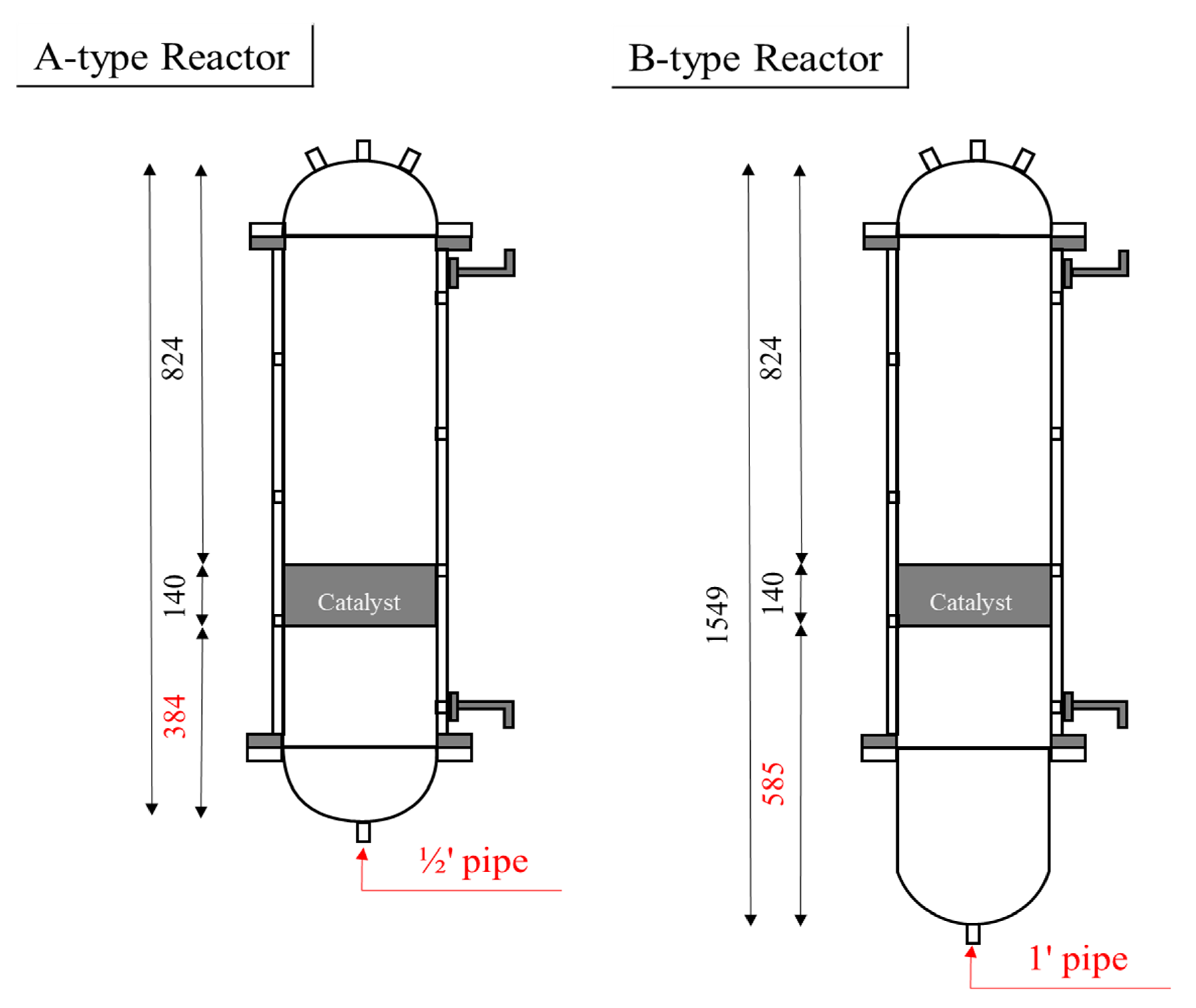
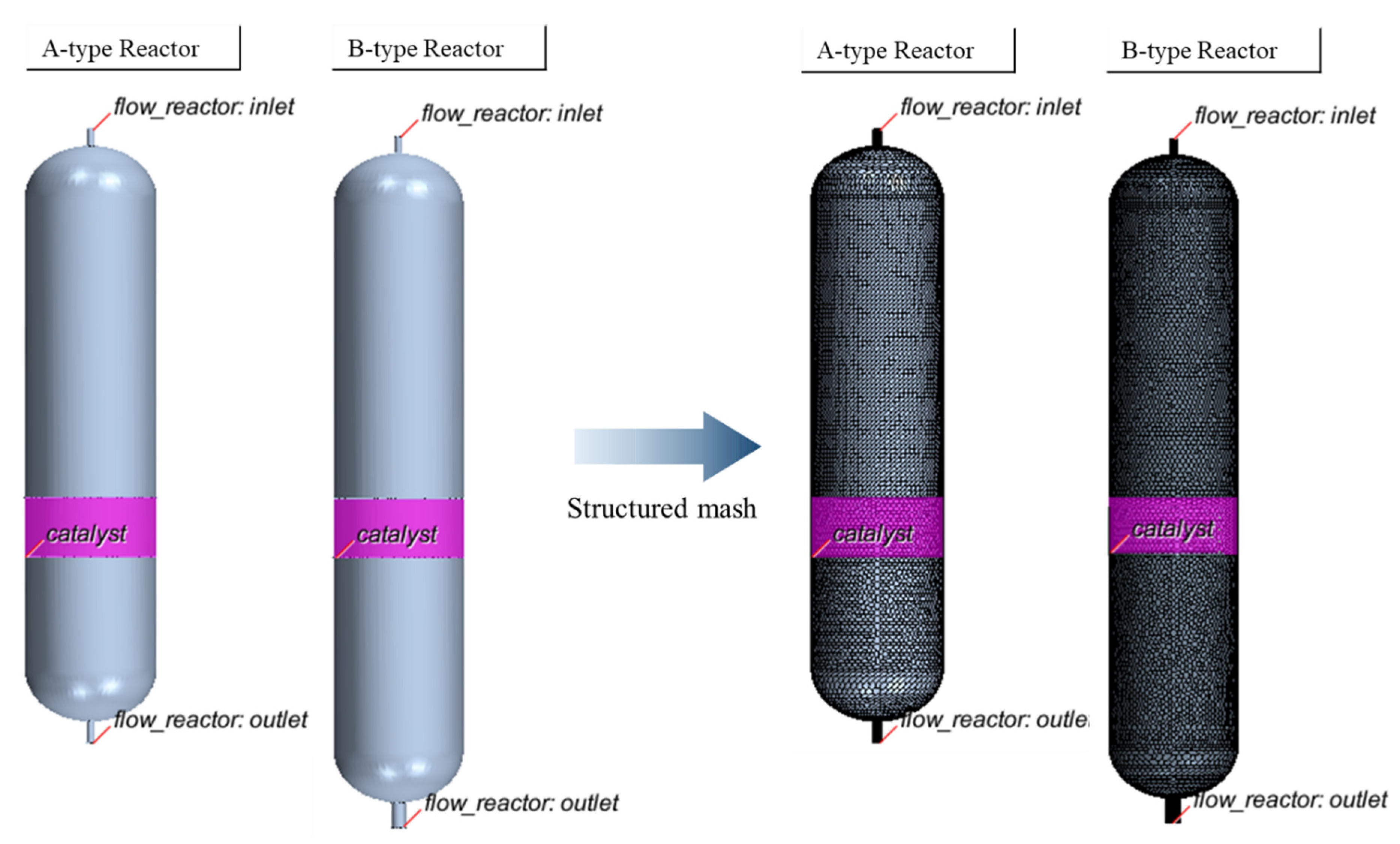
2.1. CFD Results for the CO2 Methanation Reactor

In this study, two types of CO2 methanation reactors were designed, and their internal response characteristics were compared using CFD modeling. Through modeling, we simulated the flow of fluid, temperature distribution, and composition of exhaust gas in terms of stoichiometry and predicted the efficiency of the catalyst. A comparative analysis of the two reactor types revealed that the B-type reactor consisting of a longer latter part was better than the A-type reactor in terms of fluid characteristics, temperature distribution, and CO2 conversion. Details of the analysis results are described in Section 2.1.1, Section 2.1.2 and Section 2.1.3.

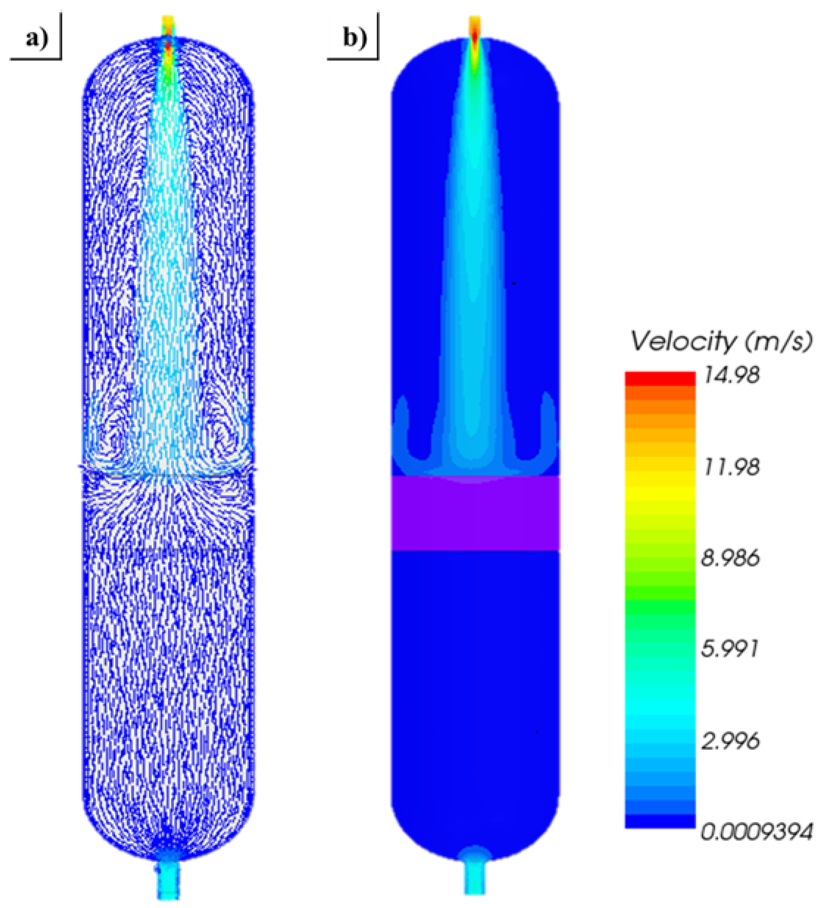
2.1.1. Cold-Flow Simulation

Figure 1 represents the result of velocity vector fields and velocity magnitudes of particles, which were analyzed through CFD analysis (excluding chemical reactions). It can be observed that, when reactive gases such as hydrogen and carbon dioxide were injected through the upper nozzle, a flow widely diverged from the upper to the lower side owing to the reactor characteristics. A large recirculation area was formed around the top of the catalyst bed when the fluid finally reached it. The increased time that a fluid resided in a reactor led to an improved CO2 conversion efficiency, but it accompanied an exothermic reaction, which resulted in thermal accumulation at the top of the catalyst bed. Accordingly, to control the heat accumulation due to the exothermic reaction when operating a plant, this study turned off the heating system and the cooling system was allowed to be used when required.

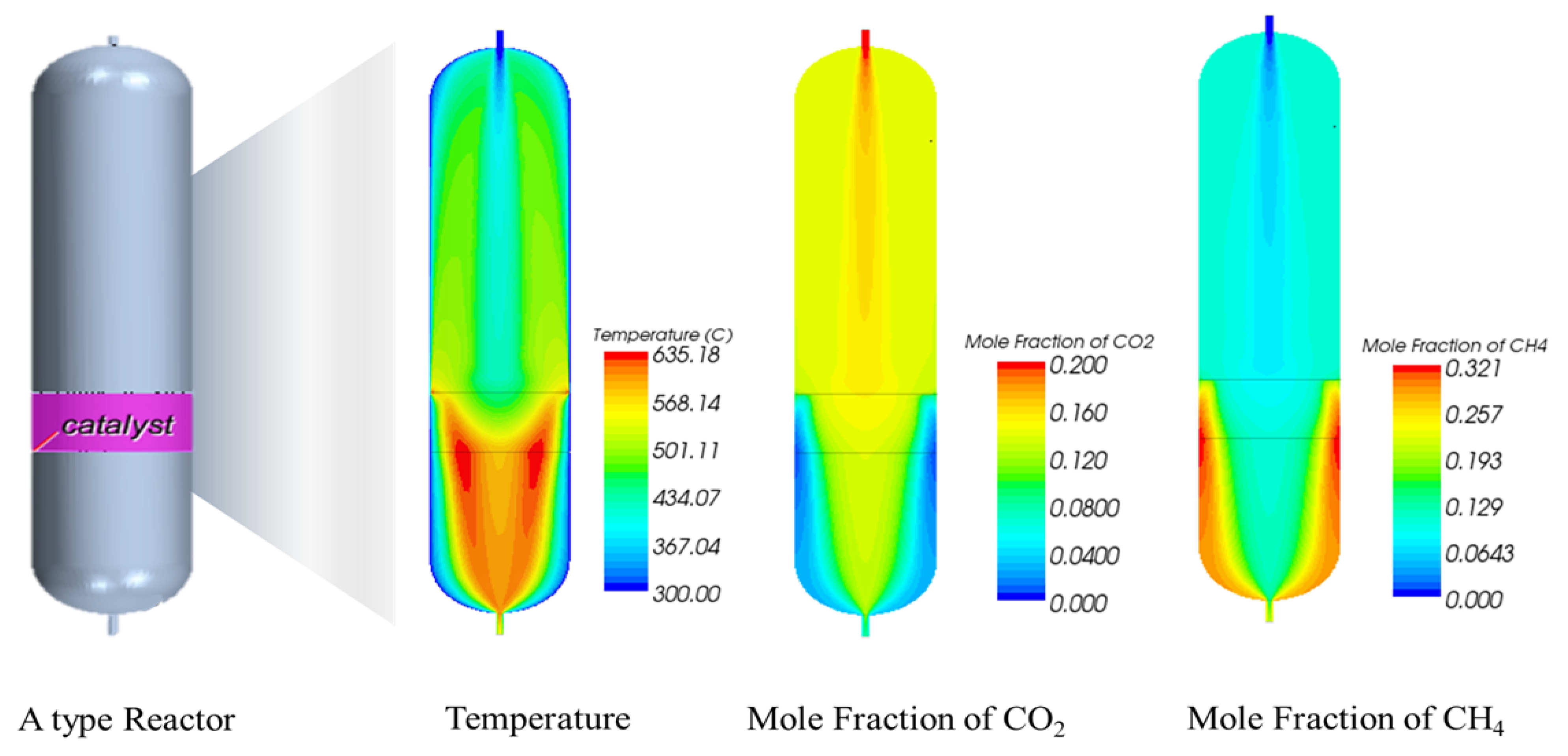
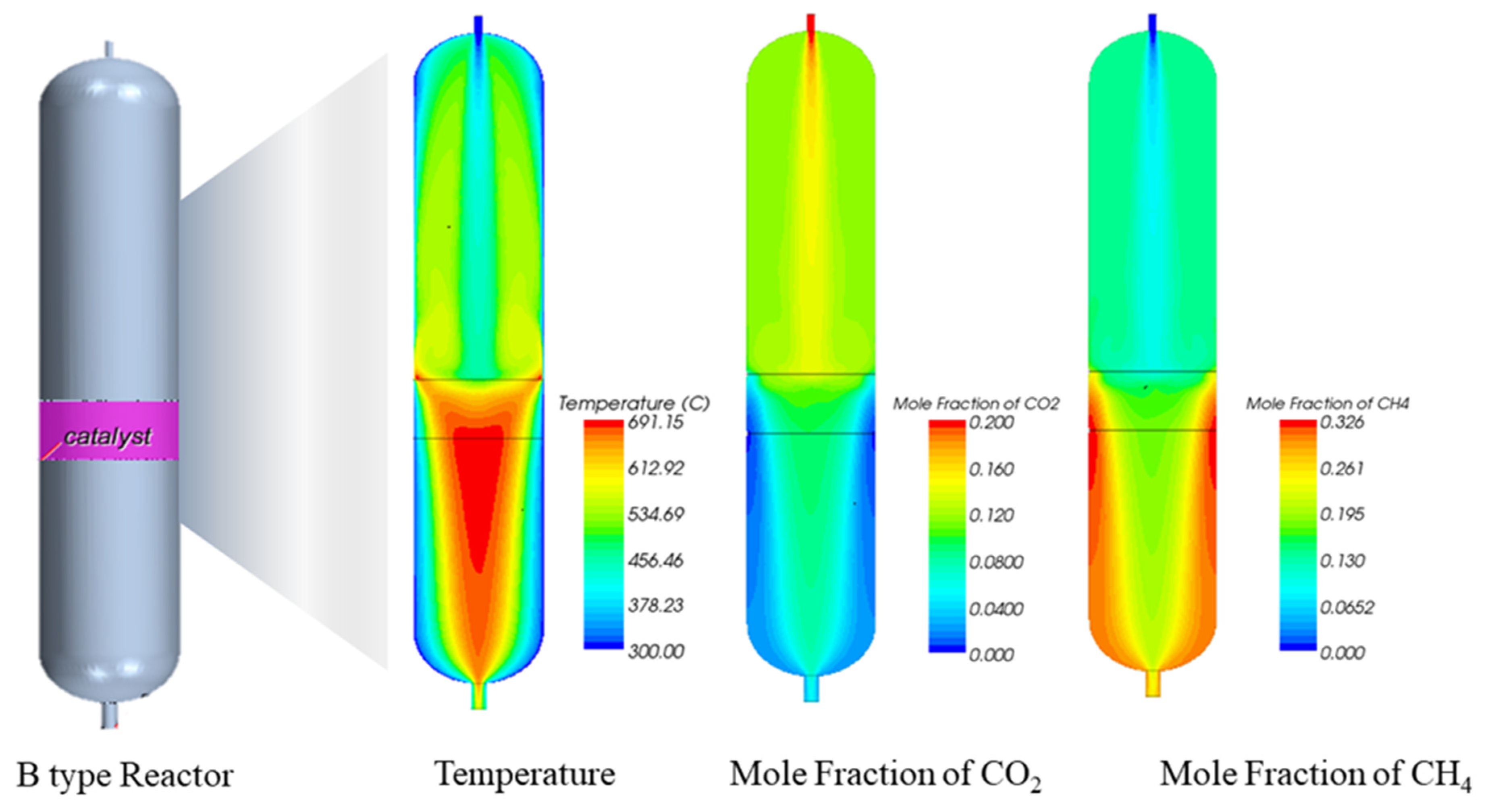
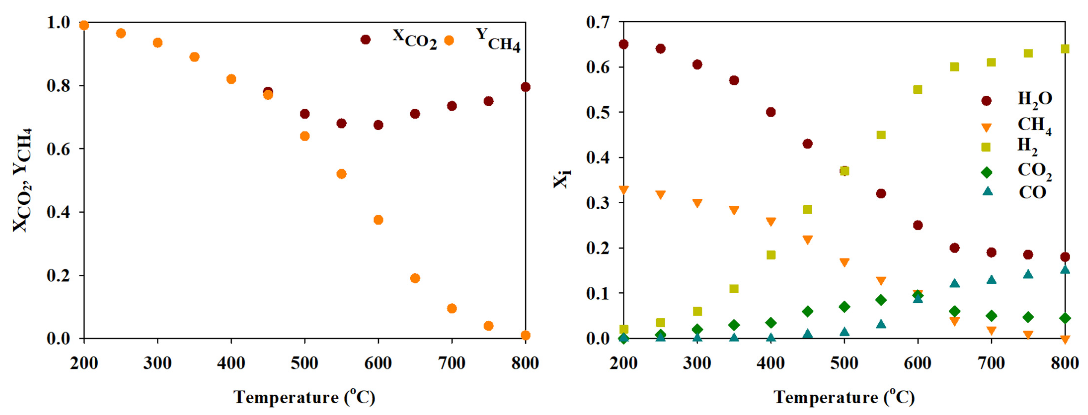
2.1.2. Reacting-Flow Simulation

The CFD analysis results that simulated the chemical reaction under actual reactive temperature and pressure conditions are shown in Figure 2 and Figure 3 and are presented in Table 1. Figure 2 and Figure 3 exhibit the distribution of temperature and CO2 and CH4 mole fractions according to the types of reactors. The temperature distribution revealed that the B-type was better than the A-type reactor as heat was uniformly distributed near the catalyst bed of the former reactor. Likewise, the reacting flow CFD analysis results are presented in Table 1. The average temperature at the exit of the reactor was 14 °C lower than that of the A-type reactor at 484 and 498 °C, respectively. Conversely, it was revealed that the temperature of the gas flowing at 300 °C increased to 400 °C at an exit after the catalytic reaction. Similarly, with respect to the composition of exhaust gas concentration, the A-type reactor contained 6.78% CO2 and 22.05% CH4, while the B-type contained 3.75% CO2 and 27.15% CH4. When calculating the CO2 conversion rate based on the results, that of the A-type was calculated to be 76.7% (assuming CH4 selectivity of 1), and that of the B type was calculated to be 88% (assuming CH4 selectivity of 1). Therefore, the cold-flow and reacting-flow CFD analysis indicated that the B-type reactor had a better CO2 conversion efficiency.

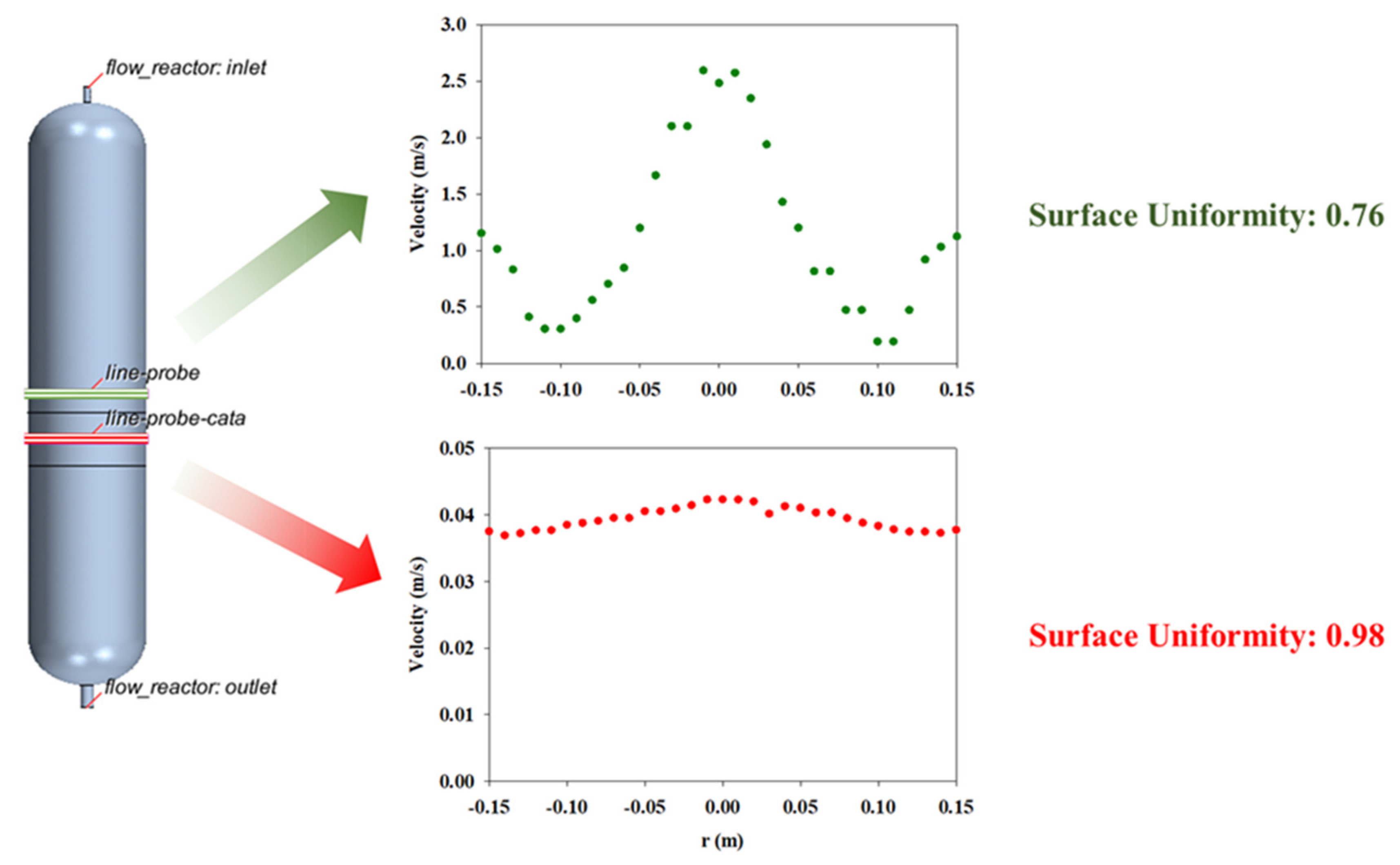
2.1.3. Flow Uniformity

The uniformity index describes the distribution of a certain quantity on a surface. If the quantity is distributed equally, the resulting number is 1. This report is useful in applications where a uniform flow rate is desired across an entire area. Heat exchangers, catalysts, and filters are examples of such applications. Therefore, flow uniformities were calculated on the surface immediately before the catalyst and at the center of the catalyst. Figure 4 shows the velocity profile and flow uniformity at the center of the upper section when the reactive gases reached the catalyst bed. The velocity profile at the center of the upper section, 5 cm away from the catalyst bed, indicated the maximum velocity at the center of the reactor, which increased subsequently because of the recirculating flow near the wall. The fluid uniformity in the upper section was estimated to be 0.76. The higher the fluid uniformity, the higher the catalyst performance. As shown in Figure 4, when the reactive gas passes the catalyst bed, the velocity is distributed uniformly, and the surface uniformity is calculated to be 0.98. The velocity of passing a catalyst bed was estimated as 0.04 m/s, which the author assumes is sufficient residence time (3.5 s) required for chemical reactions in the catalyst area. The CO2 conversion at the exit of the reactor was estimated to be 88%, which is close to 90% of the theoretical maximum conversion rate.

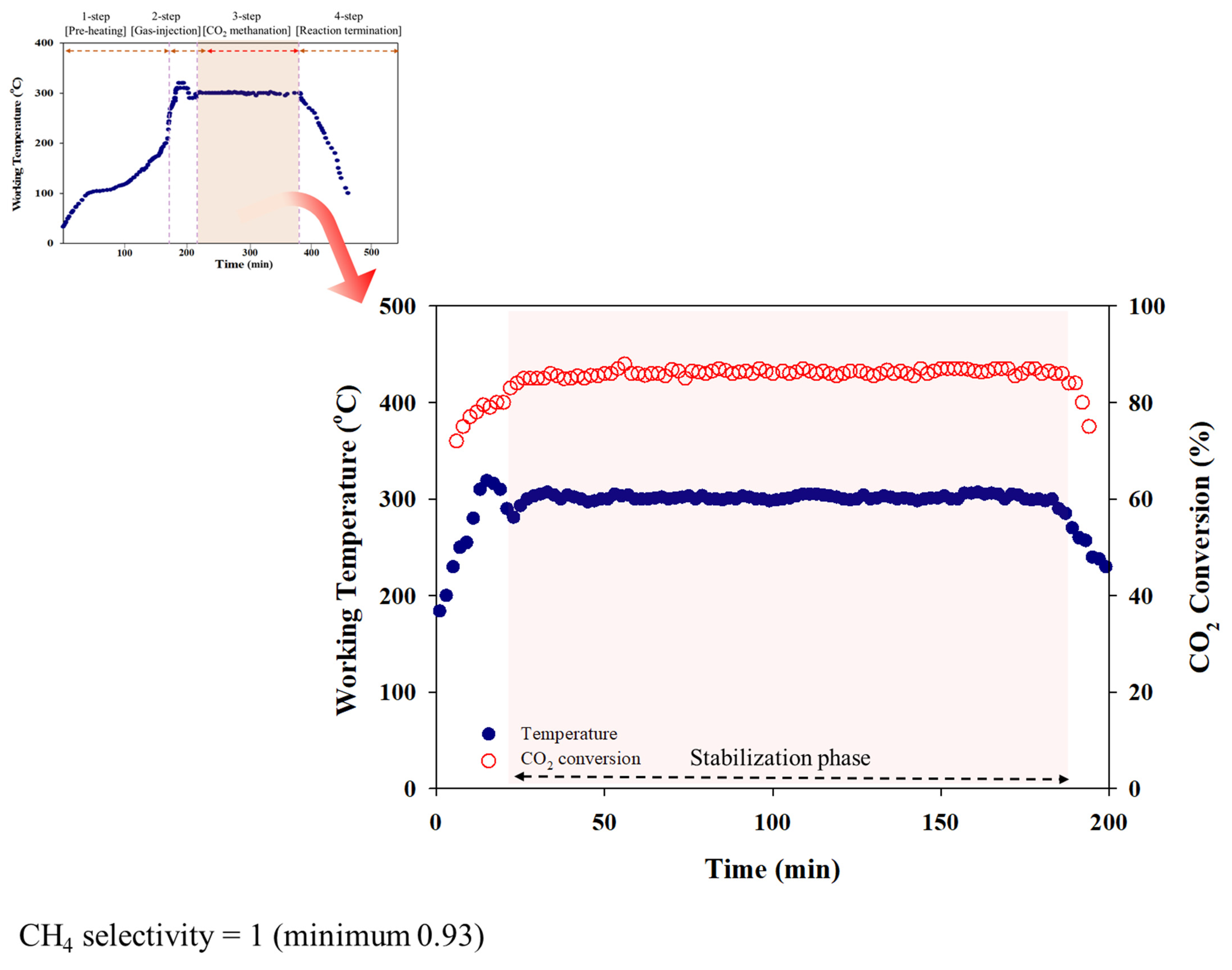
2.2. Pilot Plant Operating Real Data (CO2 Methanation)

Figure 5 shows the results of CO2 conversion at the CO2 methanation reactor installed in the sewage disposal plant, and it was found that the CO2 conversion efficiency was 85–89% (average 86%) and the CH4 selectivity was measured to be 1 (minimum 0.93) at the stabilization phase, wherein CO2 begins to convert in to CH4. At a CO2 conversion rate of 86% and CH4 selectivity of 1, the exhaust gas is composed of 16.34% H2, 4.31% CO2, 26.45% CH4, and 52.9% H2O. CH4 is produced at around 1806 L/h.
The theoretical equilibrium conversion was investigated to compare the catalytic efficiency (Figure 6) [23]. The theoretical equilibrium conversion rate under the same temperature, pressure, and gas ratio was found to be up to 94% of CO2 conversion (that in the case of nonreactive gas is 6%). Additionally, the CO2 conversion rate was predicted to be 88% through CFD modeling, as described in Section 2.1.2. The gas composition through simulation was 15% H2, 3.75% CO2, 54.1% H2O, and 27.15% CH4. Therefore, the average efficiency (86%) and CO2 methanation result values drawn from actual pilot plants are seemingly satisfactory.

2.3. CO2 Methanation-System Energy Balance

The energy balance of the CO2 methanation system was reviewed based on the data obtained from the field. In the electrolysis process to produce hydrogen, Alkaline Electrolyzes (AEL) equipment needs 4.5~7.0 kWh to produce 1 Nm3 of hydrogen [24]. However, in this section, other processes (ex. electrochemical processes) associated with the CO2 methanation system were excluded from the energy balance calculation. The amount of energy required for the CO2 collection was calculated as 1320 kWh/ton CO2 (50 Nm3/day) based on a previous study [25]. Similarly, for efficient CO2 methanation, the CO2 conversion rate was set to 86% and the CH4 selectivity was set to 1 (to calculate the energy balance), which was established based on values drawn from the field (Table 2.).
The total electric power consumed while operating the CO2 methanation process was calculated to be 1100 KWh/ton CO2, including the preheater, reactor, and cooling system. Initially, the electric power for the reactor was consumed for pre-heating; however, after reaching the steady state, electric power was not required due to the heat produced by the exothermic reaction. When 43.3 Nm3/day of CH4 was produced through the CO2 methanation reaction, 1 Nm3 of CH4 could be converted to 4389 KWh/ton CO2 of energy based on the total calories (8570 kcal). The heat of reaction generated when CO2 was converted to CH4 was calculated based on Equation (4) and was estimated to be 1038 KWh/ton CO2:
CO2 + 4H2 → CH4 + H2O, ∆ −165 KJ·mol−1
Thus, it is possible to obtain an electrical energy equivalent to 3007 kWh/ton CO2.

3. Experimental and Method

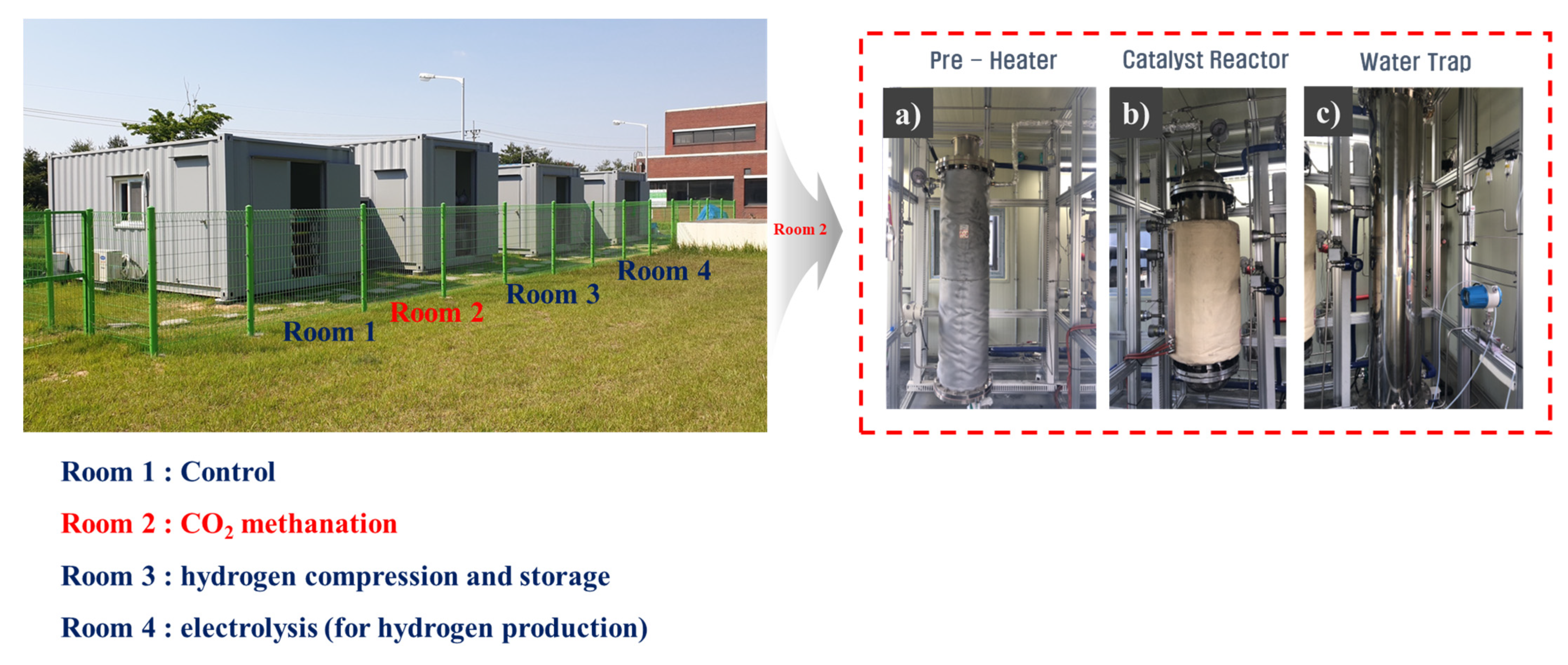
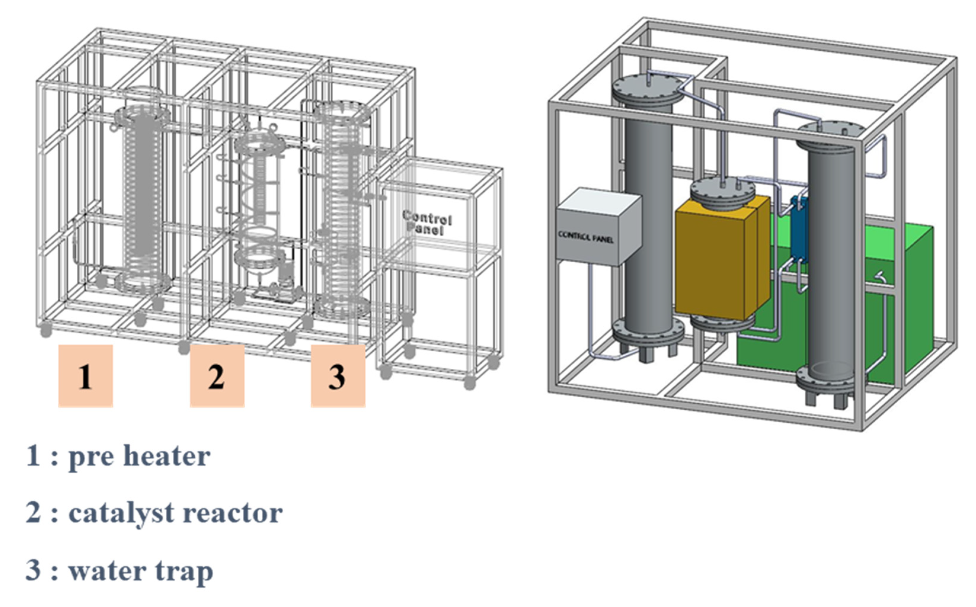
3.1. Pilot Plant Description

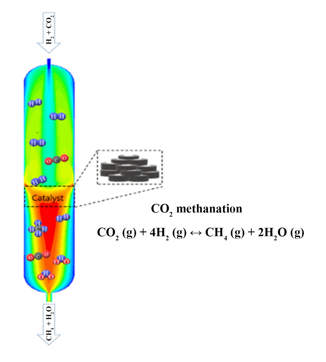
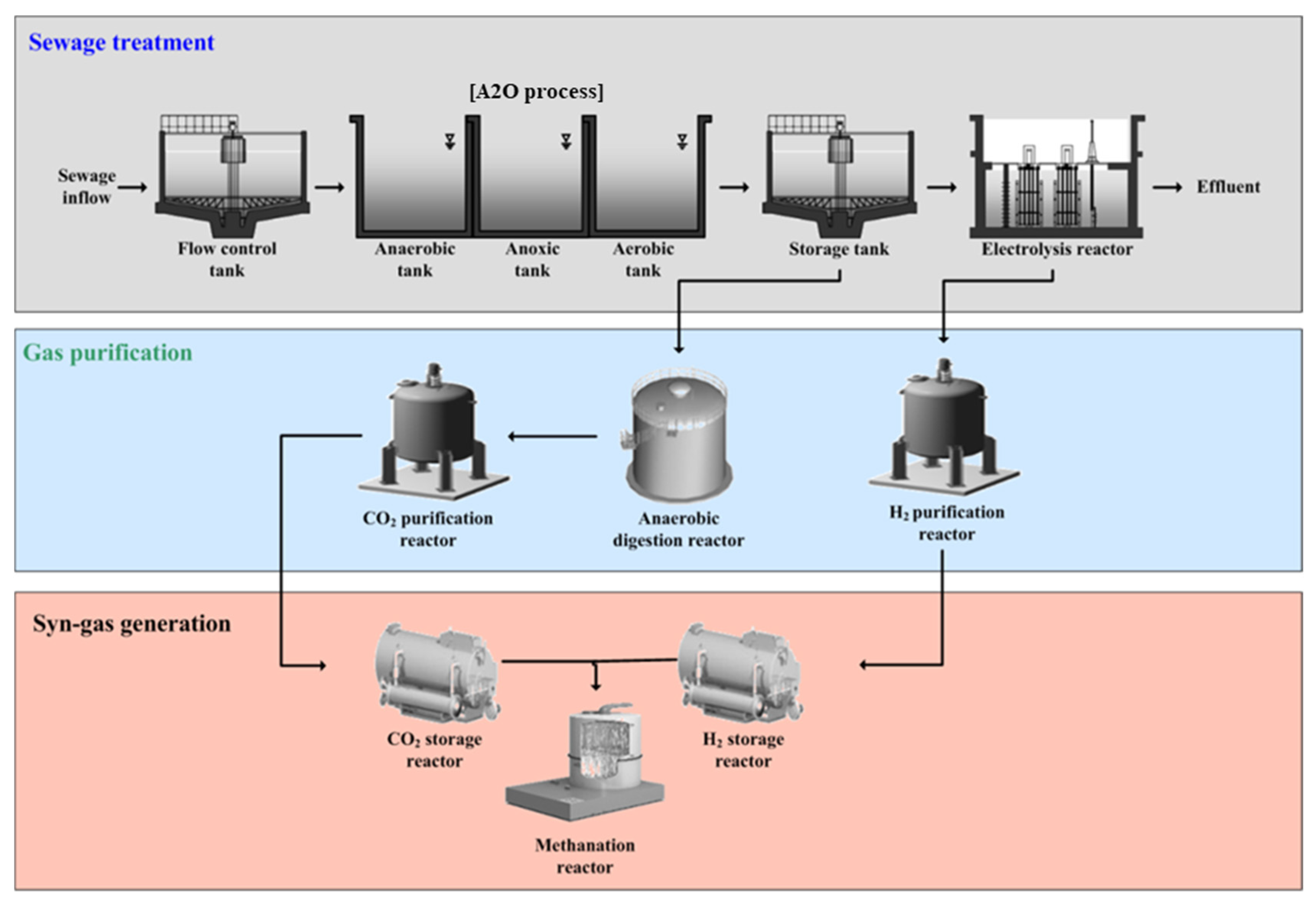
3.1.1. CO2 Methanation Technology Applied to Sewage Disposal Plants

The CO2 methanation process installed in Korea’s sewage disposal plant is 250 Nm3/day based on the inlet gas (CO2, H2). It receives CO2 and H2 from the anaerobic digestion and electrochemical processes in the sewage disposal plant, respectively. CO2 and H2 generated from the respective processes were compressed and stored as their purities were low, and subsequently entered the CO2 methanation process. However, in this study, commercial gas was purchased and tested to facilitate the gas supply when testing a pilot-scale CO2 methanation plant. Figure 7 shows a mimetic diagram of the overall process. Figure 8 shows a photograph of an actual sewage disposal plant.

3.1.2. Pilot Scale Fixed Bed Methanation System

The pilot-sized CO2 methanation system used in this study was designed to produce CH4 by treating H2 and CO2 at 250 Nm3/day at a temperature of approximately 300 °C through a catalytic reaction. Methanation installation consists of (1) pre-heating, (2) a catalyst reaction, and (3) moisture removal. The pre-heating temperature is set to 200–250 °C, which removes any residual moisture that may be contained in H2 and CO2. Additionally, the pressure was kept constant by increasing the gas temperature before the gas entered the catalyst reactor. The catalyst reaction involves the CO2 methanation reaction in a reactor, wherein the catalyst is filled to produce CH4 and H2O. Subsequently, to remove the moisture, gasified moisture through the water trap in the moisture removal step was removed. The final gas emission was measured using an NDIR-gas analyzer (Fuji Electric Co., Tokyo, Japan).
The methanation installation was designed based on safety and convenience for the overall system to control explosive hydrogen, and it displays the following characteristics. The CO2 methanation setup was installed in an explosion-proof container, and the system was designed to withstand a pressure of up to 50 bar. Safety devices, such as flame traps and check-valves, were installed. The system was designed with an alarm to sense danger, and the operation stopped automatically when the set pressure or temperature was exceeded during the operation to lower the danger. The overall CO2 methanation system is automatic and operates without contact and can control, monitor, and accumulate data in real time. Figure 9 shows the design of the CO2 methanation system.

3.2. Materials and Methods

3.2.1. Preparation of Pellet Catalysts

This study selected a Ni–0.2Ce–0.1Zr catalyst with excellent CO2 methanation performance as a powder catalyst. Reagents used in manufacturing the Ni–0.2Ce–0.1Zr catalyst were Ni powder (Sigma-Aldrich Chemical, St Louis, MI, USA), cerium nitrate hexahidrate (Aldrich Chemical, Missouri, United States of America), and zirconium oxide (Sigma-Aldrich Chemical, St Louis, MI, USA), and such a catalyst was manufactured through the wet impregnation method. The manufactured powder catalyst was sifted through a 50 μm sift for the smooth formation and coating. The powder catalyst was placed in an extruder and pressure was applied, and was then baked for its manufacture as pellets (Figure 10). Meanwhile, XRD and H2-TPR were analyzed to confirm the physicochemical properties of the pellet catalyst (Figures S1 and S2). Ni, NiO, Ce, and Zr peaks were confirmed on the catalyst surface through XRD results. H2-TPR analysis showed high H2 consumption near 300 °C.

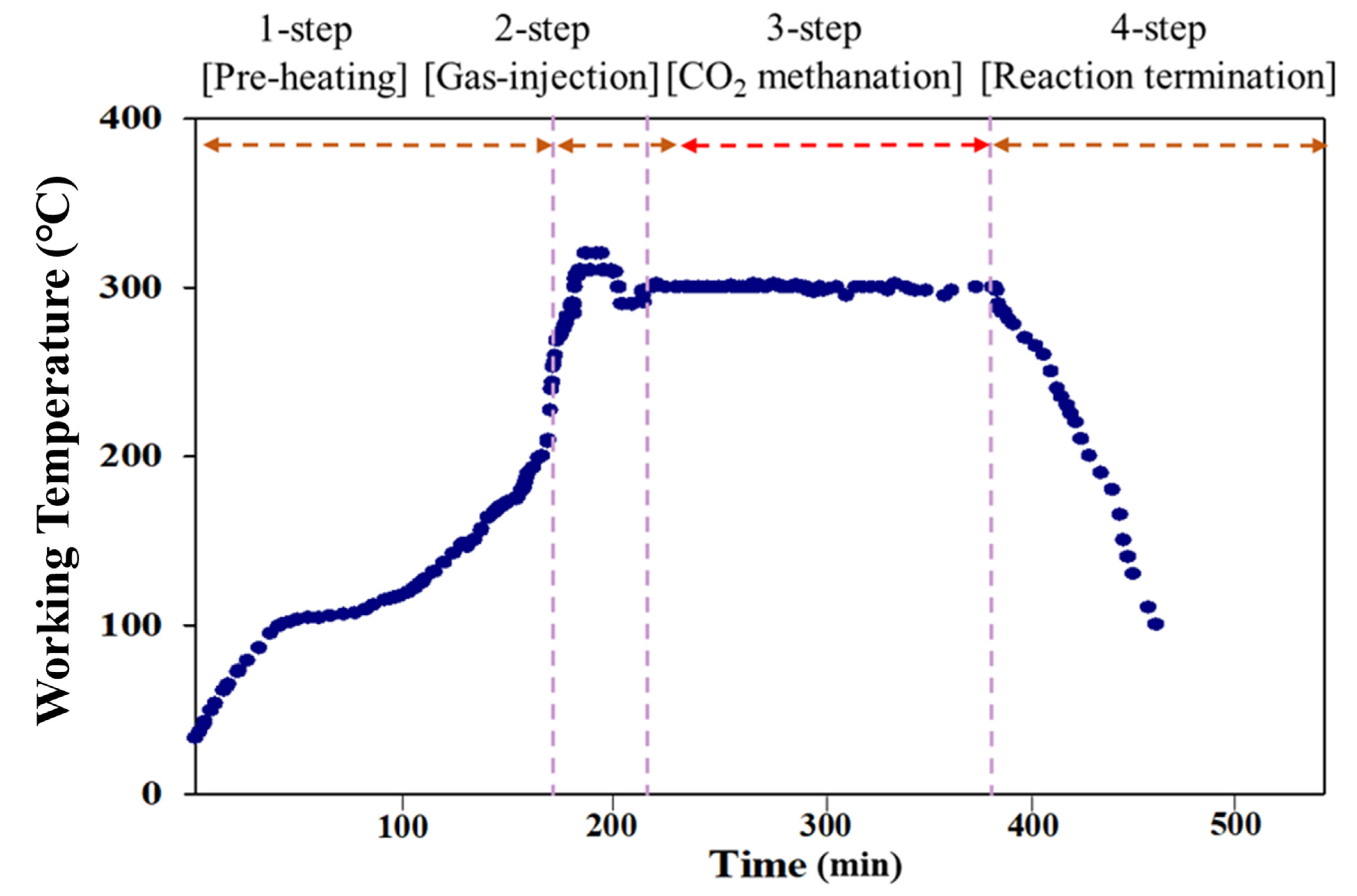
3.2.2. Operating Setup of the Pilot Scale Plant

It is necessary to reestablish the operation method due to differences in the gas flux and preheating time when the experiment was conducted in a laboratory that was a scaled-up pilot plant. Accordingly, the pilot-sized CO2 methanation process involves four steps. Step 0 involved the operation of the system after checking for flammable materials around the reactor. In step 1, which was the pre-heating step, the temperature was increased gradually to 200–250 °C in a H2 atmosphere to preheat the reactor and remove impurities in the catalyst and any remaining moisture (Figure 8a). In step 2, H2 and CO2 were injected into the reactor through gas-injection (Figure 8b). Then, CH4 began to be produced, and the temperature in the reactor increased due to the exothermic reaction. Therefore, the temperature was maintained at 300 °C and optimized for catalyst efficiency through the repeated cooling and heating system in the reactor. In step 3, which is the stabilized stage, the CH4 production depends on the reaction time. In step 4, only H2 is injected to remove H2O and other impurities in the reactor after the operation ends, thereby lowering the temperature of the reactor. Figure 11 shows the detailed operating steps. The experimental conditions are listed in Table 3. The catalyst reaction activity was expressed as the conversion to CO2 and calculated using Equations (5) and (6). The space velocity was calculated using Equation (7).
CO 2   Conversion   ( % )   =   CO 2 IN     CO 2 OUT CO 2 IN × 100
CH 4   selectivity   =   CH 4 OUT CO 2 IN     CO 2 OUT
GHSV   ( gas   hour   space   velocity )   ( h 1 )   =   Q IN Vout

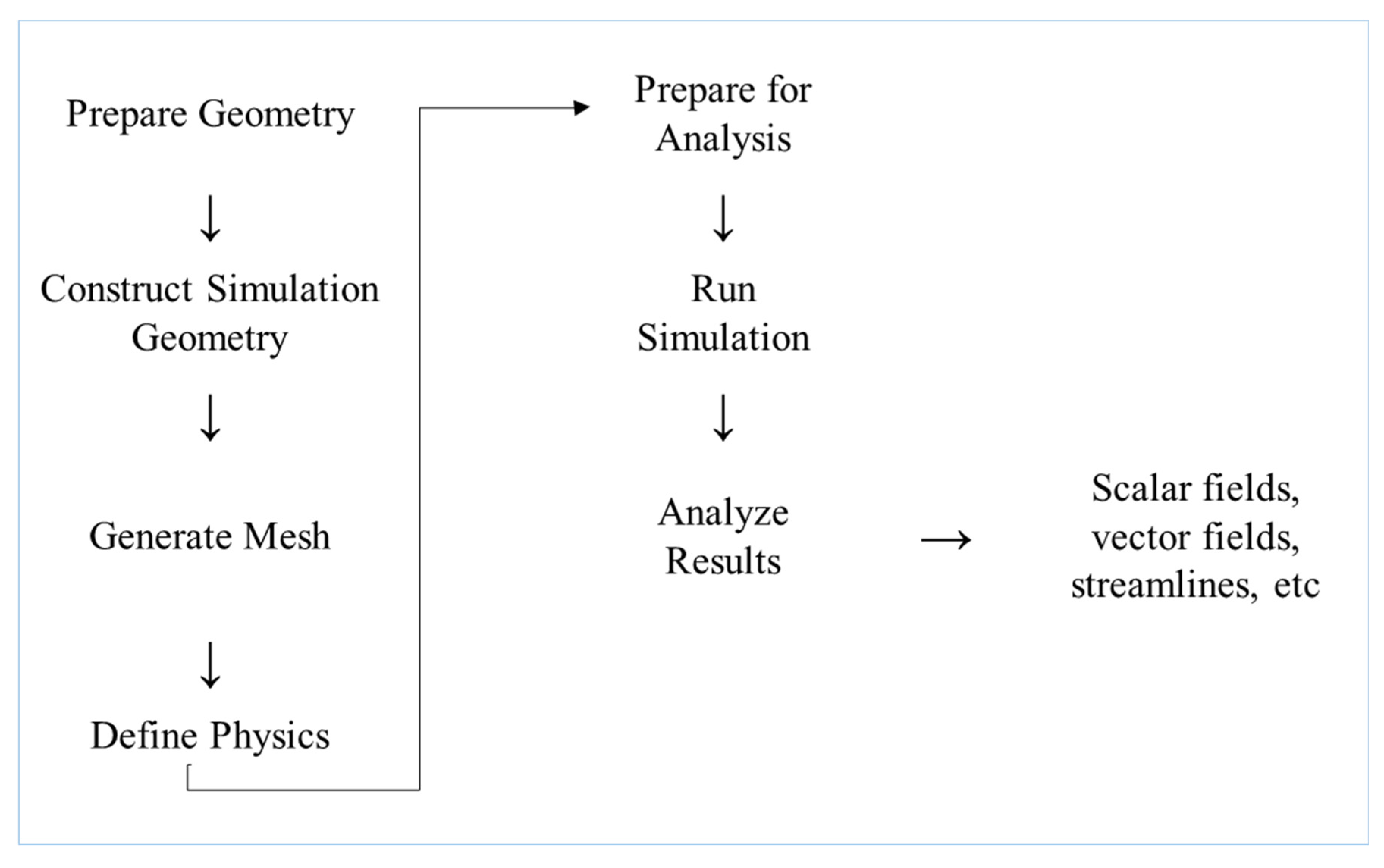
3.3. CFD Approach for Reactor Design of CO2 Methanation

In this study, the STAR-CCM+ 8.02 was used to optimize the CO2 methanation reactor effectively. Two types of pilot-sized reactors were designed to evaluate the effects of reactor design, such as changes in the length of reactor parts and the entrance and exit sizes of the reactor, to evaluate the maximum reaction efficiency through CFD analysis. Figure 12 shows a schematic diagram of two fixed bed reactors, A and B, where the B-type reactor was modified with a longer latter part compared to the A-type reactor and, subsequently, their maximum reaction efficiencies were evaluated through CFD analysis.
Similarly, the computational domain in a fixed-bed reactor for CFD analysis that produces a polyhedral mesh is shown in Figure 13. For the A-type reactor, approximately one hundred thirty thousand meshes were used for the calculation. For the B-type reactor, approximately one hundred sixty thousand meshes were used for the calculation. The relevant information is listed in Table 4. Scheme 1 illustrates the CFD analysis procedures, which are largely classified into the pre-processing (involved in building the reactor shape, generating a lattice, and establishing a numerical analysis), solving, and post-processing stages to analyze the result.
The numerical analysis model conditions used were steady state, multi-component gas, partially premixed combustion (only in the catalyst), eddy breakup model, and realizable k-ε. For the catalyst, the Ergun equation assuming isotropy was used. For the chemical reaction CO2 (g) + 4H2 (g) ↔ CH4 (g) + 2H2O (g), ∆H°298K = −165 KJ·mol−1 was assumed to be a fast chemistry model known as the Sabatier reaction.
First, it was determined whether the design was appropriate through cold-flow simulation (fluid flow state without chemical reaction). Then, CFD results through hot-flow simulation (the fluid stream containing the reaction conditions) from reflecting the actual conditions were compared.

4. Conclusions

In this study, to recycle CO2 generated from sewage treatment plants, an associated process based on the CO2 methanation technology was presented, and CH4 production was calculated through methanation. The data required for the reactor design to predict the maximum catalyst efficiency were obtained by conducting CFD simulations for various design factors (entrance and exit sizes, length of the latter part of the catalyst, etc.).
Experiments were conducted by selecting a B-type reactor, which was validated through CFD modeling. The CO2 methanation efficiency was measured to be 85–89%, and 1806 L/h of CH4 was produced. This was observed to be similar to the values predicted by the CFD modeling. Despite being a pilot-sized plant, stable and high methane production efficiency has been observed for a long time. Based on the results, the energy balance of the CO2 methanation system was calculated, and, finally, energy equivalent to approximately 3007 kWh/ton CO2 could be obtained. The findings of this study are expected to serve as a foundation for producing economically viable CH4, which is an alternative energy source and industrial application of CO2 methanation technology.

Supplementary Materials

The following are available online at https://www.mdpi.com/article/10.3390/catal11081005/s1, Figure S1: XRD patterns of catalyst, Figure S2: H2-TPR profile of Pellet catalyst.

Author Contributions

Conceptualization, J.A. and W.C.; methodology, J.A. and Y.R.; modeling, H.K.; validation, J.A., H.K. and W.C.; formal analysis, J.A. and Y.R.; investigation, J.A. and H.K.; data curation, J.A. and J.K.; writing—original draft, J.A.; writing—review and editing, H.K., J.K., W.C. and S.C.; supervision, W.C. and S.C. All authors have read and agreed to the published version of the manuscript.

Funding

This work was supported by the Korea Institute of Energy Technology Evaluation and Planning (KETEP) and the Ministry of Trade, Industry & Energy (MOTIE) of the Republic of Korea (No. 20183020141270).

Data Availability Statement

Not applicable.

Acknowledgments

This work was supported by the Korea Institute of Energy Technology Evaluation and Planning (KETEP) and the Ministry of Trade, Industry, and Energy (MOTIE) of the Republic of Korea (No. 20183020141270).

Conflicts of Interest

The authors declare no conflict of interest.

References

  1. Norbert, E.; Duchel, S.; Sung Jin, K.; Andreas, O.; Sun Jin, Y.; Gi Eun, K. KAS Journal on Contemporary Korean Affairs, Environmental Policy in South Korea: Problems and Perspectives; Konrad Adenauer Stiftung: Seoul, Korea, 2015; pp. 45–48. [Google Scholar]
  2. European Commission. A Policy Framework for the Climate and Energy in the Period from 2020 to 2030. 2014. Available online: https://ec.europa.eu/clima/policies/strategies/2030_en (accessed on 20 August 2021).
  3. Frédéric David, M.; Frédéric-Paul, P.; Suren, E. Power-to-gas through CO2 methanation: Assessment of the carbon balance regarding EU directives. J. Energy Storage 2017, 11, 16–24. [Google Scholar]
  4. Rocha, A.; Pereira, S.C.; Viceto, C.; Silva, R.; Neto, J.; Marta Almeida, M. A consistent methodology to evaluate temperature and heat wave future projections for cities: A case study for Lisbon. Appl. Sci. 2020, 10, 1149. [Google Scholar] [CrossRef] [Green Version]
  5. Wei, Z.; Hiroshi, M.; Hiroyuki, T.; Koichi, I.; Koyo, N. Computational fluid dynamics simulation of CO2 methanation in a shell-and-tube reactor with multi-region conjugate heat transfer. Chem. Eng. Sci. 2020, 211, 115–276. [Google Scholar]
  6. Yamasaki, M.; Habazaki, H.; Yoshida, T.; Akiyama, E.; Kawashima, A.; Asami, K.; Komori, M.; Shimamura, K. Compositional dependence of the CO2 methanation activity of Ni/ZrO2 catalysts prepared from amorphous Ni-Zr alloy precursors. Appl. Catal. A Gen. 1997, 163, 187–197. [Google Scholar] [CrossRef]
  7. Götz, M.; Lefebvre, J.; Mörs, F.; McDaniel, K.; Graf, F.; Bajohr, S. Renewable Power-to-Gas: A Technological and Economic Review. Renew. Energy 2016, 85, 1371–1390. [Google Scholar] [CrossRef] [Green Version]
  8. Coronado Martín, I. Carbon Dioxide Methanation for Intensified Reactors. In Proceedings of the Aalto University School of Chemical Technology Degree Programme in Chemical Technology, Helsinki, Finland, 9 March 2015. [Google Scholar]
  9. Beatrice, C.; Alberto, M.G.; Elena, M.; Benedetto, N.; Andrea, P.; Mirko, F.; Andrea, N.; Federico, R. Experimental Investigation on CO2 Methanation Process for Solar Energy Storage Compared to CO2-Based Methanol Synthesis. Energies 2017, 10, 855. [Google Scholar]
  10. Shohei, T.; Teruyuki, S.; Hiromichi, K.; Takahide, H.; Ryuji, K. Ni/CeO2 catalysts with high CO2 methanation activity and high CH4 selectivity at low temperatures. Int. J. Hydrog. Energy 2012, 37, 5527–5531. [Google Scholar]
  11. Han, D.; Kim, Y.; Byun, H.; Cho, W.; Baek, Y. CO2 methanation of biogas over 20 wt% Ni-Mg-Al catalyst: On the effect of N2, CH4, and O2 on CO2 conversion rate. Catalysts 2020, 10, 1201. [Google Scholar] [CrossRef]
  12. Pastor Pérez, L.; Baibars, F.; Le Sache, E.; Arellano García, H.; Gu, S.; Reina, T.R. CO2 valorisation via Reverse Water-Gas Shift reaction using advanced Cs doped Fe-Cu/Al2O3 catalysts. J. CO2 Util. 2017, 21, 423–428. [Google Scholar] [CrossRef] [Green Version]
  13. Jinghua, X.; Xiong, S.; Hongmin, D.; Baolin, H.; Qingquan, L.; Xiaoyan, L.; Xiaoli, P.; Guangxian, P.; Haoran, G.; Yanqiang, H.; et al. Influence of pretreatment temperature on catalytic performance of rutile TiO2-supported ruthenium catalyst in CO2 methanation. J. Catal. 2016, 333, 227–237. [Google Scholar]
  14. Beuls, A.; Swalus, C.; Jacquemin, M.; Heyen, G.; Karelovic, A.; Ruiz, P. Methanation of CO2: Further insight into the mechanism over Rh/γ-Al2O3 catalyst. Appl. Catal. B Environ. 2012, 113–114, 2–10. [Google Scholar] [CrossRef]
  15. Takano, H.; Shinomiya, H.; Izumiya, K.; Kumagai, N.; Habazaki, H.; Hashimoto, K. CO2 methanation of Ni catalysts supported on tetragonal ZrO2 doped with Ca2+ and Ni2+ ions. Int. J. Hydrog. Energy 2015, 40, 8347–8355. [Google Scholar] [CrossRef]
  16. Rynkowski, J.; Paryjczak, T.; Lewicki, A.; Szynkowska, M.I.; Maniecki, T.P.; Jozwiak, W.K. Characterization of Ru/CeO2-Al2O3 catalysts and their performance in CO2 methanation. React. Kinet. Catal. Lett. 2000, 71, 55–64. [Google Scholar] [CrossRef]
  17. Dea Heun, M.; Woo Jin, C.; Soon Woong, C.; Sang Moon, L.; Sung Su, K.; Jae Hoon, J.; Yeon Hee, R.; Jeong Yoon, A.; Wenshan, G.; Huu Hao, N.; et al. Fabrication and characterization of Ni-Ce-Zr ternary disk-shaped catalyst and its application for low-temperature CO2 methanation. Fuel 2020, 260, 116–260. [Google Scholar]
  18. Jeong Yoon, A.; Soon Woong, C.; Sang Moon, L.; Sung Su, K.; Woo Jin, C.; Jung Chul, L.; Yong Joo, C.; Kyung Sook, S.; Dea Heun, M.; Dinh Duc, N. Developing Ni-based honeycomb-type catalysts using different binary oxide-supported species for synergistically enhanced CO2 methanation activity. Fuel 2019, 250, 227–284. [Google Scholar]
  19. Dea Heun, M.; Sang Moon, L.; Jeong Yoon, A.; Dinh Duc, N.; Sung Su, K.; Soon Woong, C. New Ni-based Quaternary Disk-Shaped Catalysts for Low-Temperature CO2 Methanation: Fabrication, Characterization, and Performance. J. Environ. Manag. 2018, 218, 88–94. [Google Scholar]
  20. Yu Jin, J.; Sung Gil, H.; Min Choul, K.; Jae Jeong, L.; Gang Woo, L.; Byung Hyun, S. Numerical Study for Flow Uniformity in Selective Catalytic Reduction(SCR) Process. J. Korea Acad. Ind. Coop. Soc. 2011, 12, 4666–4672. [Google Scholar]
  21. Hey Suk, K.; Seung Hee, C.; Min Jung, H.; Woo Young, S.; Mi Soo, S.; Dong Soon, J.; Sang June, Y.; Young Chan, C.; Gae Goo, L. Numerical and Experimental Study on the Coal Reaction in an Entrained Flow Gasifier. J. Korean Soc. Environ. Eng. 2010, 32, 165–174. [Google Scholar]
  22. Mi Soo, S.; Hey Suk, K.; Ji Eun, H.; Dong Soon, J. A numerical Study for improvement of indoor Air Quality of Apartment House. J. Korean Soc. Environ. Eng. 2009, 31, 521–530. [Google Scholar]
  23. Lars, K.; Jorg, T. Predicting optimal temperature profiles in single-stage fixed-bed reactors for CO2-methanation. Chem. Eng. Sci. 2016, 132, 59–71. [Google Scholar]
  24. Gonzatti, F.; Nizolli, V.; Ferrigolo, F.Z.; Farret, F.A.; de Mello, M.A.S. Experimental Hydrogen Plant with Metal Hydrides to Store and Generate Electrical Power. Int. J. Emerg. Electr. Power Syst. 2016, 17, 59–67. [Google Scholar] [CrossRef]
  25. Frédéric, D.M.; Vincent, M.; Suren, E. Material constraints related to storage of future European renewable electricity surpluses with CO2 methanation. Energy Policy 2016, 94, 366–376. [Google Scholar]
Figure 1. Velocity plot by cold-flow analysis: (a) velocity vector fields and (b) velocity magnitudes.
Catalysts 11 01005 g001
Figure 2. Reacting flow simulation for the A-type reactor.
Catalysts 11 01005 g002
Figure 3. Reacting-flow simulation for the B-type reactor.
Catalysts 11 01005 g003
Figure 4. Hot−flow simulation result of the B−type reactor.
Catalysts 11 01005 g004
Figure 5. CO2 methanation data in the pilot plant (inlet gas CO2:H2 = 1:4, actual temperature 300 ± 5 °C)).
Catalysts 11 01005 g005
Figure 6. Equilibrium conversion rate (left) and the product fraction of CO2 methanation at equilibrium (right), p = 1 bar, H2/CO2 = 4.
Catalysts 11 01005 g006
Figure 7. Process diagram of carbon resource integration.
Catalysts 11 01005 g007
Figure 8. CO2 methanation processes installed in sewage disposal plants in Korea: (a) pre-heater, (b) catalyst reactor, and (c) water trap.
Catalysts 11 01005 g008
Figure 9. Pilot plant of CO2 methanation in a sewage disposal plant in Korea.
Catalysts 11 01005 g009
Figure 10. Structure of the manufactured pellet-type catalyst.
Catalysts 11 01005 g010
Figure 11. Four steps of the CO2 methanation process.
Catalysts 11 01005 g011
Figure 12. Schematic of the CO2 methanation reactor.
Catalysts 11 01005 g012
Figure 13. Computational domain and mesh generation of the two types of CO2 methanation reactors.
Catalysts 11 01005 g013
Scheme 1. Workflow process for simulation.
Catalysts 11 01005 sch001
Table 1. Composition of temperature and exhaust gases according to reactor types.
Reactor TypeAB
Exit-gas temperature (°C)497484
Exit-gas compound
(vol%)
CO26.783.75
CH422.0527.15
Table 2. CO2-methanation energy balance.
UnitData
CO2Nm3/day50
Capture CO2kWh/ton CO21320
CO2-methanation systemkWh/ton CO21100
CH4 gasNm3/day43.3
Chemical energy (CH4)kWh/ton CO24389
Recoverable heatkWh/ton CO21038
Table 3. Experimental conditions.
Experimental Conditions
Flow rateH2
(Nm3/h)
8.33
CO2
(Nm3/h)
2.08
Average working temperature (°C)300
Max working temperature360
Catalyst typepellet type
Ni–0.2Ce–0.1Zr
Space velocity (h−1)1950
Working pressure (bar)1–1.2
Table 4. Mesh constitution of reactor type.
Number of grid (Cells)Type 1127,348
Type 2157,095
mesh typePolyhedral mesh
Publisher’s Note: MDPI stays neutral with regard to jurisdictional claims in published maps and institutional affiliations.

