Article

NiCo Nanoneedles on 3D Carbon Nanotubes/Carbon Foam Electrode as an Efficient Bi-Functional Catalyst for Electro-Oxidation of Water and Methanol

by
Tung Ngoc Pham
1,2,*,
Ajaikumar Samikannu
1,
Solomon Tesfalidet
1,
Thomas Wågberg
3 and
Jyri-Pekka Mikkola
1,4,*
1
Chemical-Biological Centre, Technical Chemistry, Department of Chemistry, Umeå University, SE-90187 Umeå, Sweden
2
Faculty of Chemistry, The University of Danang-University of Science and Technology, 54 Nguyen Luong Bang, Lien Chieu, Da Nang 550000, Vietnam
3
Department of Physics, Umeå University, SE-90187 Umeå, Sweden
4
Process Chemistry Centre, Industrial Chemistry & Reaction Engineering, Department of Chemical Engineering, Åbo Akademi University, FI-20500 Åbo-Turku, Finland
*
Authors to whom correspondence should be addressed.
Catalysts 2021, 11(4), 500; https://doi.org/10.3390/catal11040500
Submission received: 18 March 2021 / Revised: 8 April 2021 / Accepted: 12 April 2021 / Published: 15 April 2021
(This article belongs to the Special Issue Design and Applications of Bifunctional Catalysts)

Abstract

:
In this study, we report a 3D structured carbon foam electrode assembled from a bi-functional NiCo catalyst, carbon nanotubes (CNT), and a monolith 3D structured carbon foam (CF) as a highly active and stable electrode for oxygen evolution reaction (OER) and methanol oxidation reaction (MOR). When the NiCo@CNTs/CF electrode was used as an anode in OER, after the anodization step, the electrode required a small overpotential of 320 mV to reach the current density of 10 mA cm−2 and demonstrated excellent stability over a long testing time (total 30 h) in 1 M KOH. The as-prepared NiCo@CNTs/CF electrode also exhibited a good performance towards methanol oxidation reaction (MOR) with high current density, 100 mA cm−2 at 0.6 V vs. Ag/AgCl, and good stability in 1 M KOH plus 0.5 M CH3OH electrolyte. The NiCo@CNTs/CF catalyst/electrode provides a potential for application as an anode in water electrolysis and direct methanol fuel cells.

1. Introduction

In order to minimize the impact of non-renewable fossil fuels on the environment, the utilization of renewable electricity from renewable energy sources, such as solar and wind, is being rapidly expanded on a worldwide scale. Due to the supply–demand imbalance of electricity, sustainable storage, and conversion devices that convert electricity to another form of energy that later can be converted back to electricity are highly necessary [1]. Water electrolysis is one of the most attractive methods used to transform electrical energy to renewable hydrogen gas owing to the high purity of the produced hydrogen and, additionally, the environmentally friendly nature of the technology. In the water electrolysis process, under an applied potential, hydrogen is produced at cathode by hydrogen evolution reaction (HER), and oxygen gas is evolving at the anode through oxygen evolution reaction (OER) in which the sluggish kinetics of OER is the main cause leading to the higher energy consumption in the electrolysis system [2,3]. On the other hand, due to some major disadvantages of hydrogen fuel such as high cost, and complications in storage and transport, the cheaper and much safer methanol is investigated to be used as a fuel in a direct methanol fuel cell (DMFC), in which the methanol electro-oxidation reaction (MOR) at the anode is the most crucial. Unfortunately, similar to OER where noble metal-based catalysts such as IrO2 and RuO2 show their excellent electrocatalytic activities [2,4], precious metals such as Pt, Ru, and Pd are found to be very active for MOR [5,6,7]. These, however, display practical limitations owing to the high price and scarcity of these noble metals. Thus, electrocatalysts based on non-precious metals such as iron, nickel, and cobalt were studied as alternatives for noble metals [8,9,10,11,12].
In particular, earth-abundant catalysts such as metal oxides and hydroxides [13,14,15,16,17] and metal hybrids [18,19,20,21,22,23,24,25] have been widely studied as promising electrocatalysts for OER owing to their low price, high activity, and good stability. Among these earth-abundant electrocatalysts, NiCo based catalysts, such as NiCo2O4 and NiCo hydroxides, which can be easily synthesized through hydrothermal or electrodeposition methods [26,27,28,29,30,31,32] have attracted significant research interest as promising electrocatalysts for OER and also MOR. Besides, due to advantages, such as high electrical conductivity, large geometric surface area, and 3D open pore structure that facilitate the dispersion of electrolytes, as well as generated gases, nickel foam was selected as a substrate in many studies [26,27,28,29,31,33,34,35,36,37]. Despite its reputation, nickel foam has some major disadvantages, i.e., high cost and being a non-eco-friendly material due to the complex and high energy demanding manufacturing procedure [38,39]. Compared with nickel foam, carbon materials are considered as cheaper and more eco-friendly materials owing to the lower energy demand required for their production, as well as handling of the waste. Thus, carbon-based materials mainly comprising carbon fiber paper, carbon cloth, and glassy carbon were used as an electrode substrate [8,32,40,41,42,43] in some studies but still at a much lesser extent compared with that of nickel foam.
In this study, we developed a 3D structured carbon-based electrode NiCo@CNTs/CF in which the carbon nanotubes and carbon foam were completely covered by the nanoneedles of NiCo catalyst which can be used as a bi-functional catalyst for OER and MOR. The smart design electrode has many advantages originating from the property of each component such as the good electrocatalytic activity of the NiCo catalyst, high electrical conductivity, and high chemical resistance of CNTs, further coupled to the 3D open-pore cell structured of the carbon foam [44]. For OER, boosted by anodization process, the electrode requires a small overpotential of only 320 mV to reach the current density of 10 mA cm−2. Furthermore, the developed electrode showed excellent stability in a series of galvanostatic tests (30 h in total), at a constant current density of 10 mA cm−2 in 1 M of KOH electrolyte. For MOR, the NiCo@CNTs/CF also exhibits remarkable performance where the electrode shows high electrocatalytic activity in which a high current density of 100 mA cm−2 was achieved at 0.6 V vs. Ag/AgCl in1 M KOH with 0.5 M methanol. Moreover, the prepared electrode also shows outstanding stability with no decay observed in the current density during potentiostatic tests at the constant potential of 0.4 V vs. Ag/AgCl. This raises the potential of the electrode to be used as an efficient, low-cost, and eco-friendly anode for OER in a water splitting system as well as MOR in a direct methanol fuel cell.

2. Results and Discussion

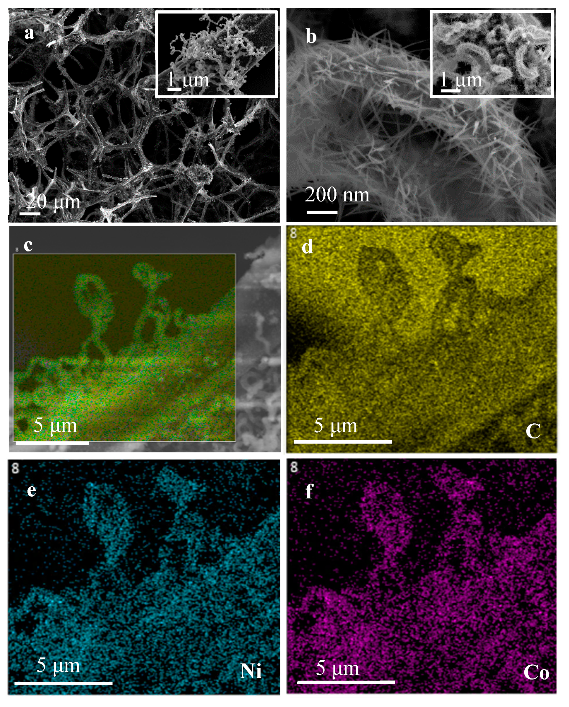
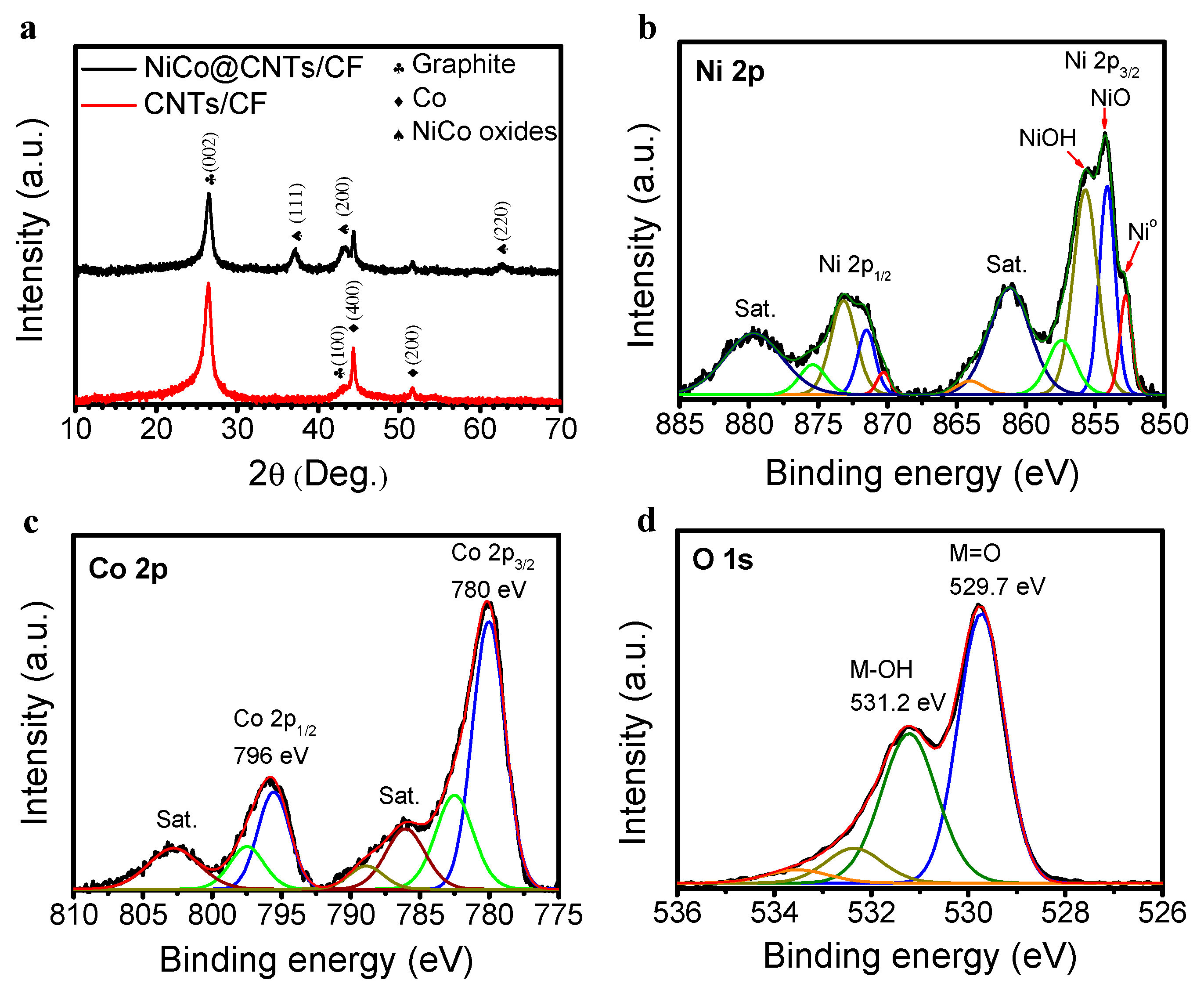
2.1. Material Characterizations

The morphology of synthesized carbon nanotubes (CNT) on carbon foam (CF) and NiCo catalyst on the CNTs/CF were revealed using the SEM technique. Figure 1a shows the 3D open-pore structure of carbon foam with the curved carbon nanotubes on the carbon frame which remained after the pyrolysis and catalytic chemical vapor deposition (CCVD) processes. After the catalyst decoration step, the surface of the sample (NiCo@CNTs/CF) was completely covered by needle-like nanostructures that have a length of more than 200 nm (Figure 1b) which is expected to have a big impact on the surface area of the material. To address this issue, the B.E.T. surface area of CNTs/CF and NiCo@CNTs/CF samples was calculated based on nitrogen sorption and desorption analysis of the corresponding samples (Figure S1). The results showed that the NiCo@CNTs/CF has a higher specific surface area (~110 m2 g−1) than the support surface (CNTs/CF, ~87 m2 g−1), due to the presence of NiCo nanostructures. The distribution of Ni and Co elements on the surface of NiCo@CNTs/CF was investigated using the energy-dispersive X-ray spectroscopy (EDS) mapping analysis. To investigate the distribution of Ni and Co elements, the energy dispersive X-ray spectroscopy (EDS) mapping analysis of NiCo@CNTs/CF sample was performed. The acquired images (Figure 1c–f), in which carbon, nickel, and cobalt were indexed in yellow, blue, and purple colors, respectively, illustrate a homogeneous distribution of Ni and Co throughout the carbon frame. The catalyst loading of the sample, determined using thermal gravimetric analysis (TGA) measurement on NiCo@CNTs/CF and CNTs/CF, was found to be ca 22.5 wt.% (Figure S2). This was further supported by inductively coupled plasma optical emission spectroscopy (ICP-OES), where the measurement of Ni and Co in digested NiCo@CNTs/CF, estimating the atomic ratio of Ni–Co to be 1.3–1, resulted in a catalyst loading of ~ 21.7 wt.%.
The crystalline phase of the as-made NiCo@CNTs/CF, and also the blank (CNTs/CF) samples were studied by the X-ray diffraction (XRD) technique. As shown in Figure 2a, the XRD pattern of CNTs/CF sample exposes the presence of CNTs by peaks at the 2θ of 27.8°, and 44° and also Co0, using as a catalyst for CNTs, through peaks at the 2θ of 44.6°, and 51° [45]. On the other hand, the XRD pattern of the pristine NiCo@CNTs/CF displays several new peaks at 2θ of ~37°, 44°, and 63.0° which, based on the value in the standard card of JCPDS card # 48–1719 (CoO) and 04–0835 (NiO), can be characterized as CoO, and NiO. The chemical composition and oxidation states of Ni and Co in the fresh NiCo@CNTs/CF sample were determined using XPS analysis. The XPS wide spectrum of the sample confirms the presence of Ni, Co, C, N, and O in the sample (Figure S3). As can be seen from Figure 2b, the deconvoluted spectrum of Ni 2p3/2 shows the presence of 3 nickel components that can be assigned as metallic (852.8 eV), oxide (854.1 eV), and hydroxide (855.7 eV) [46]. The oxidation stage of cobalt in the sample was also identified through the Co 2p high-resolution spectrum (Figure 2c) where the two main peaks at 780 eV (Co 2p3/2) and 796 eV (Co 2p1/2) entailed that the major amount of cobalt in the sample surface is in the oxide form [46,47]. The oxidation state of nickel and cobalt are further confirmed by O 1s spectra (Figure 2d): the two main peaks at 529.7 and 531.5 eV can be assigned to metal-bound oxygen (M=O) and metal-bound hydroxide (M–OH) group [46], respectively, in which the first peak is the dominating peak. Thus, based on XRD and XPS results, we can conclude that our as prepared catalyst contains three phases in which the phase of metal oxides is dominant.

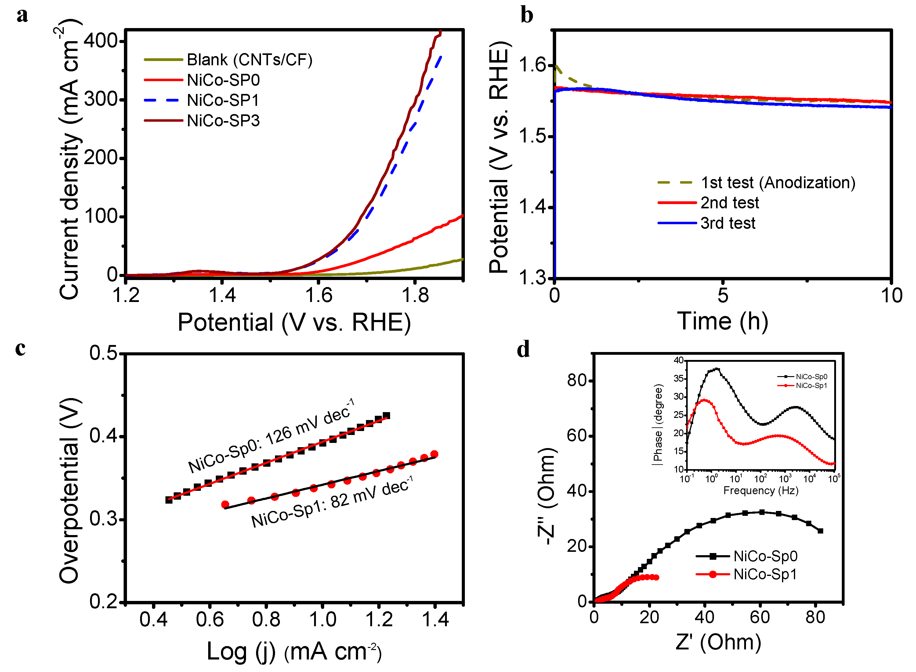
2.2. The OER Performance

The OER activity of the NiCo@CNTs/CF, before and after the anodization, was investigated by polarization scans at 5 mV s−1 in 1 M KOH. As shown in Figure 3a, the pristine electrode, named as NiCo-Sp0, exhibits a quite low electrocatalytic activity which needs an overpotential of approximately 400 and 660 mV to reach the current density of 10 and 100 mA cm−2, respectively. To improve the performance towards OER of the electrode, an anodization step was included at a constant current density of 10 mA cm−2 in 10 h in 1 M KOH which also can be considered as the 1st galvanostatic cycle (Figure 3b). After the anodization step, the electrode, entitled NiCo-Sp1, shows a huge enhancement of the electrocatalytic activity in which the overpotential (ɳ) that corresponds to the current density of 10 mA cm−2 dropped to below 320 mV, which is comparable with other reported NiCo based catalysts but still higher than that of the benchmark catalysts, e.g., NiFe based catalysts (Table S1). Moreover, the Tafel plots (Figure 3c) obtained from the polarization curves show a similar result where the calculated Tafel slope of the NiCo-Sp1 (82 mV dec−1) is much smaller than that of the NiCo-Sp0 (127 mV dec−1), indicating improved catalytic kinetics of the catalyst after the anodization step. It is worth mentioning that the estimated Tafel slope value of the NiCo@CNTs/CF (NiCo-SP1) is similar to the reported values of NiCo based catalysts which also is in agreement with the overpotential values (Table S1). To explain the enhancement, electrochemical impedance spectroscopy (EIS) experiment was conducted before and after the anodization step at the overpotential of 0.3 V. Remarkably, the Nyquist plots of the pristine and anodized electrodes (Figure 3d) show two semicircles which is not often seen in common OER electro-catalyst systems [48]. The achieved Nyquist plots can be explained using a model (Figure S4) in which the semicircle at the high frequency region is linked to the resistivity of the topmost oxide layer which the current has to pass through before reaching underlying layers of the catalyst/electrode, the charge transfer resistance (Rct in the model). The second semicircle found at the low frequency domain is associated with the underlying compact oxide layer [49] in which R1 is the resistivity of the layer. Using the model, the Rct value of the NiCo-Sp1 Nyquist plot was estimated to be ~20 Ω which is much smaller than that of the fresh catalyst, NiCo-Sp0 (~97 Ω). As shown in the corresponding Bode-phase diagrams (Figure 3d (inset)), the two peaks at low (from 10−1 to 101 Hz) and medium-high (from 103 to 105 Hz) region are in agreement with the two semicircles observed in Nyquist plots. Interestingly, after the anodization process, the peaks were found to be shifted towards the low frequency region which implied a dramatic change in the characteristics of the NiCo catalyst. The result indicates that after the anodization, the NiCo catalyst possesses a lower charge transfer resistance and also faster kinetics in OER than the fresh catalyst. Furthermore, the double layer capacitance (Cdl) of the electrode before and after the anodization which is directly proportional to the electrochemically active surface area (ECSA), was estimated using cyclic voltammograms (CV) in a non-Faradaic potential region (Figure S5). After the anodization, the Cdl value of NiCo@CNTs/CF was calculated to be 24.5 mF cm−2 which is approximately double the Cdl value of the pristine electrode (13.1 mF cm−2). The higher value of Cdl indicates that after the anodization, the electrode has more active sites for the water oxidation reaction leading to the observed increase in the OER performance of the electrode.
To investigate the stability of the NiCo@CNTs/CF after the anodization step, two consecutive cycles of the galvanostatic test were performed in which each cycle has the testing time of 10 h, at a constant current density of 10 mA cm−2. As shown in Figure 3b, during the 2nd as well as the 3rd test, the NiCo@CNTs/CF electrode exhibits excellent durability which shows no decrease but a slightly better electrocatalytic activity at the end of each test. The observed trend was further confirmed by the Linear Sweep Voltammetry (LSV) taken after the third test (NiCo-Sp3) which shows a slightly better OER performance than that of the NiCo-Sp1 (Figure 3a). To further study the durability of the electrode, possible leaching of Ni and Co into the electrolyte during the stability tests was checked using ICP-OES. The ICP-OES results showed no sign of the presence of Ni in the electrolyte, which probably is under the detection limit of the instrument, and only a small amount of Co (~0.4 ppm) after three consecutive galvanostatic tests (30 h in total at a constant current density of 10 mA cm−2). It is worth noting that, the amount of the leached cobalt is very small (~2.8 µg), which is only 0.2% of the total amount of the cobalt catalyst.
The morphology, as well as the chemical composition and oxidation stage of the catalyst, after the third galvanostatic test, NiCo-Sp3, were also studied by SEM and XPS techniques. The SEM images of the NiCo-Sp3 (Figure S6) reveals that the morphology of the NiCo catalyst, with needle-like structures on the surface of the CNTs/CF, has remained after the stability tests. The result from SEM-EDX elemental mapping of the NiCo-Sp3 sample has also proven for the homogeneous distribution of Ni and Co catalyst after the third galvanostatic test (Figure S7). The wide spectrum of the NiCo-Sp3 (Figure 4a) shows the presence of elements, i.e., C, O, N, Ni, and Co on the surface of the measured sample that is similar to the pristine sample. Furthermore, a tiny amount of potassium (~0.3 at.%) was found on the sample as an impurity, probably caused by the adsorption of K+ ions from the electrolyte onto the surface of the electrode. On the other hand, high resolution spectra of Ni 2p, Co 2p, and O 1s of NiCo-Sp3 reveal a tremendous change in their oxidation stage after stability tests. As shown in Figure 4b, the two peaks characterized as oxide and metal phase of nickel (at 852.8 and 854.1 eV, respectively) in the pristine catalyst (NiCo-Sp0), were depleted from the Ni 2p3/2 spectrum of NiCo-Sp3 which now shows only one peak at the binding energy of 856 eV which can be assigned to Ni(OH)2 [46]. This proves that nickel and nickel oxide reacted further with hydroxyl ions to form a layer of nickel hydroxide on the catalyst surface during the OER in KOH electrolyte, as expected [50]. Similarly, the transformation of cobalt oxide to cobalt hydroxide during the OER was also noted, where the main peak of Co 2p3/2 spectrum of NiCo-Sp3 (Figure 4c) was shifted to a higher binding energy level (780.8 eV, assigned as Co(OH)2 [46]) than that of the pristine catalyst (780 eV, assigned as cobalt oxides). Furthermore, the O 1s high-resolution spectrum (Figure 4d) shows a dominant peak at 531.6 eV assigned as the metal-bound hydroxide group (M–OH) which is much bigger than the peak of metal-bound oxygen (M=O). The results obtained from XPS confirm that during the OER the developed NiCo catalyst is converted to the corresponding hydroxide form, resulting in a much better performance toward OER than the pristine catalyst.

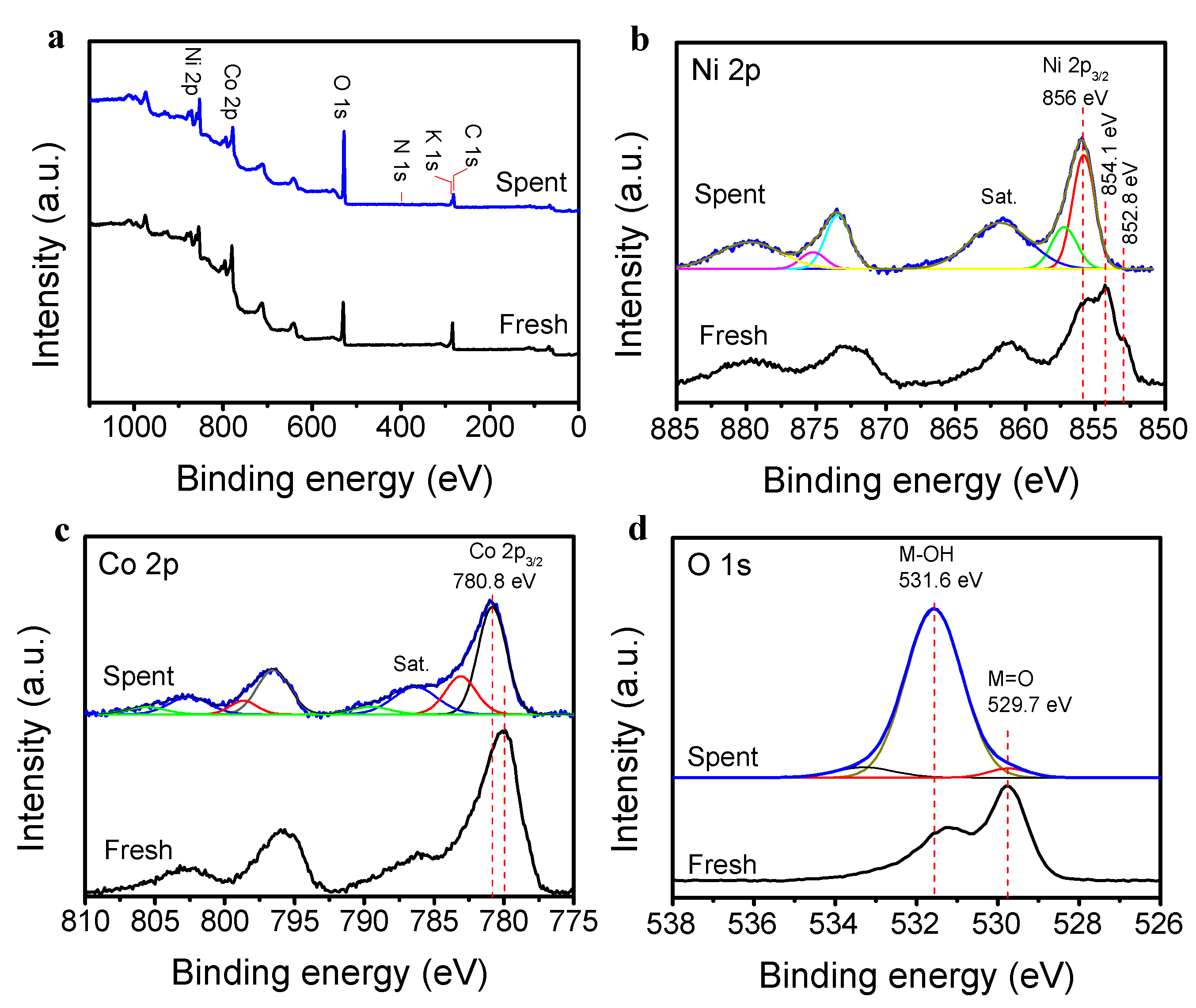
2.3. The MOR Performance

The electrocatalytic activity of the as-prepared NiCo@CNTs/CF electrode toward the methanol oxidation reaction (MOR) was investigated by CV scans which were performed before and after adding methanol (0.5 M) to the 1 M KOH electrolyte solution. As shown in Figure 5a, in the absence of methanol, the NiCo@CNTs/CF electrode exhibits very low anodic current at the potential range from 0 to ~ 0.5 V vs. Ag/AgCl owing to the high onset potential toward OER (around 0.55 V vs. Ag/AgCl) of the pristine electrode. After the addition of methanol, at the same investigated potential range, a much higher anodic current was observed which is, obviously, due to the oxidation of methanol at the electrode. Moreover, based on the CVs, the onset potential of our NiCo@CNTs/CF electrode was estimated to be only around 0.3 V vs. Ag/AgCl (Figure S8) which is similar to the previously reported results of NiCo2O4 catalyst for MOR [51,52].
To investigate the performance toward the MOR of the NiCo@CNTs/CF electrode, 3 consecutive potentiostatic tests were carried out at a constant potential of 0.4 V vs. Ag/AgCl in 1 M KOH plus 0.5 M methanol electrolyte solution. Furthermore, after each potentiostatic test, LSV and EIS techniques were used to evaluate the electrocatalytic activity of the electrode. As shown in Figure 5b, in the 1st cycle, after an apparent decrease in the current density at the beginning, the electrode shows good stability where no obvious decay in the current density was observed in 1 h. The 2nd potentiostatic test shows the same trend but with a much better MOR performance with an increase of nearly 30% in the recorded current density. The result also implies that the observed depletion of the current density at the beginning of potentiostatic tests wasn’t caused by the poisoning of the oxidation intermediate, as reported in many studies [51,53,54], but could be assigned to the mass transfer issue where the rate of diffusion of methanol from the bulk to the carbon foam electrode is slower than the consumption rate. The third test, however, exhibits a different pattern in which a more gradual decrease in the current density was observed. Despite the downward trend, a similar current density (~17 mA cm−2) as the previous potentiostatic test, was achieved at the end of the third test. To explain these findings, further investigations on the electrocatalytic activity of the NiCo@CNTs/CF electrode were performed.
To further study the electrocatalytic activity expressed as the recorded potential at the current density of 10 mA cm−2 of the NiCo@CNTs/CF electrode, after each potentiostatic cycle, linear sweep voltammetric (LSV) scans, hereafter referred as ‘LSV_Sp-x’ (where x is the order number of the potentiostatic test), were immediately conducted without any change in the electrolyte. As shown in Figure 5c, the LSV results reveal an improved performance of the electrode for MOR. The tendency can be seen through a decline in the recorded potentials at the current density of 10 mA cm−2 which dropped from ~ 0.356 V (the fresh electrode, LSV_Fresh) down to 0.335 V vs. Ag/AgCl after the 2nd potentiostatic test (LSV_Sp-2). The voltammetric response performed after the third potentiostatic test (LSV_Sp-3), showed a similar electrocatalytic activity with that of the LSV_Sp-2 which is very consistent with the results observed from the potentiostatic curves. Interestingly, after replacing the old electrolyte with a new electrolyte solution, the recorded LSV (LSV_Sp-3_CE) exhibits a slightly better electrocatalytic activity than that of the LSV_Sp-2 and also LSV_Sp-3, especially in the high potential region. At the scan rate of 10 mV s−1, a high current density of 100 mA cm−2 was obtained at 0.6 V vs. Ag/AgCl (Figure S9) which is on par with other reported ‘state-of-the-art’ non-precious catalysts for direct electro-oxidation of methanol (Table S2). The onset potential of the electrode estimated, from the LSV_Sp-3_CE curve, is only ~ 0.26 V vs. Ag/AgCl (Figure S8) which is smaller than that of the pristine electrode (~ 0.3 V). Evidently, after the third potentiostatic cycle, the NiCo@CNTs/CF electrode has better electrocatalytic activity than previously. As demonstrated by the LSV results, the trend observed for MOR is similar to that obtained for OER in which Ni and Co in alkaline electrolyte react with hydroxyl ions to form hydroxides (Reaction 1 and 2). The oxidation reaction of methanol is enhanced in the presence of metal hydroxides (Reaction 3 and 4, as described below) [50,55,56,57].
M + 2OH → M(OH)2 + 2e (M = Ni, Co)
MO + OH → MOOH + e
M(OH)2 → MOOH + H+ + e
4MOOH + 4CH3OH + 5O2 → 4M(OH)2 + 4CO2 + 6H2O
To confirm the improvement of the performance toward MOR of the NiCo@CNTs/CF electrode, EIS experiments were conducted before (EIS_Fresh) and after each potentiostatic test, hereafter referred as ‘EIS_Sp-x’ (where x is the order number of the potentiostatic test) at the potential of 0.3 V vs. Ag/AgCl. To eliminate the influence of OER on the EIS results, the potential was selected within the MOR active region but still lower than the OER onset potential of the electrode. The resulting Nyquist plots (Figure 5d) and the corresponding Bode-phase plots (Figure S10) display a similar pattern as observed in OER. Thus, the same model (Figure S4) was used to calculate the charge transfer resistance (Rct) value of EIS spectra. The results show that the calculated Rct value of the EIS_Sp-3_CE spectrum is 18.3 Ω which is much smaller than the Rct value of other EIS spectra, e.g., EIS_Sp-3, EIS_Sp-2, and EIS_Fresh (39.0, 36.8, and 57.2 Ω, respectively). The EIS results confirm the increased MOR performance, i.e., faster electron transfer and more favorable MOR kinetics of the NiCo@CNTs/CF electrode during the anodic processes. The declining trend observed during the third potentiostatic test could be due to the depletion of methanol with time. Overall, the results obtained from potentiostatic, LSVs, and EIS tests approve the excellent MOR performance of the electrode.

3. Materials and Methods

3.1. Materials

Melamine foam (Basotect G) was purchased from BASF (Ludwigshafen, Germany). Cobalt (II) acetate tetrahydrate (Co(C2H3O2)2·4H2O), nickel (II) nitrate hexahydrate (Ni(NO3)2·6H2O), cobalt (II) nitrate hexahydrate (Co(NO3)2·6H2O), and thiophene (C4H4S, 99%) were purchased from Sigma Aldrich (St. Louis, MO, USA). Dimethylformamide (DMF) was purchased from VWR (Radnor, PA, USA). Carbon glue was purchased from PELCO (Fresno, CA, USA). All chemicals were used as received.

3.2. Synthesis of Carbon Foam

The carbon foam sample (CF) was synthesized following the procedure described in our previous work [16]. Briefly, the precursor, melamine-based polymer foam (BASF, Basotect G, used as received), was pyrolyzed at 900 °C (6 h, the ramping rate of 5 °C/min) in a quartz reactor under N2 flow (50 mL min−1). After the pyrolysis, the furnace was allowed to cool down to room temperature under a nitrogen atmosphere. Finally, the synthesized CF was washed several times with water and then dried at 80 °C in air, overnight.

3.3. Synthesis of Carbon Nanotubes (CNT) on Carbon Foam

Overall, 20 mg of cobalt (II) acetate tetrahydrate was dissolved in 5 mL of dimethylformamide (DMF) and sonicated for 3 min. The carbon foam sample (~20 mg) was put into the mixture together with 65 μL of thiophene. The mixture was dried at 125 °C under nitrogen flow. To grow CNTs on the carbon foam substrate, the catalytic chemical vapor deposition (CCVD) method was employed. The sample was placed on a quartz boat which then was inserted into a horizontal quartz tube. The system was purged with the Varigon gas (5% hydrogen in argon gas, 180 mL min−1) for 20 min and then heated to 670 °C with the ramping rate of ~30 °C min−1. After that, acetylene was introduced into the system at a flow rate of ~3.8 mL min−1 for 30 min. In the meantime, the Varigon gas flow was maintained. Finally, the system was allowed to cool down to room temperature under argon gas flow (180 mL min−1).

3.4. Synthesis of Catalyst Material

NiCo catalyst was deposited on the surface of the carbon foam using the hydrothermal method. In general, 0.04 g of Ni(NO3)2·6H2O, 0.04 g Co(NO3)2·6H2O, and 0.08 g urea were dissolved in a 10 mL mixture of distilled water and ethanol (60:40) with a magnetic stirrer in around 10 min to form a clear solution. After the addition of the CNTs/CF sample (~0.01 g), the mixture was transferred to a Teflon-lined autoclave. The autoclave was sealed and then heated at 100 °C for 8 h. After the reaction, the sample was washed several times with distilled water and ethanol, then dried at 100 °C in air overnight. Finally, the carbon sample was annealed at 300 °C for 3 h in a nitrogen atmosphere (50 mL min−1).

3.5. Characterization Techniques

Scanning electron microscopy (SEM) and Energy Dispersive X-ray Spectroscopy (EDS) were carried out using a Zeiss Merlin FEG-SEM instrument (Oberkochen, BW, Germany). Thermogravimetric analysis (TGA) was conducted on a Mettler Toledo equipment (TGA/DSC 1LF, Columbus, OH, USA) operated at a heating rate of 10 °C min−1 up to 950 °C in air. The surface area measurements were carried out by N2 sorption and desorption analysis (Tristar 3000 apparatus, Micrometrics Instrument Corp., Norcross, GA, USA). The surface area of samples was calculated by multipoint nitrogen gas sorptiometry according to the Brunauer–Emmett–Teller principle. Before the analysis, the sample was degassed at 110 °C in 3 h in N2 atmosphere. The surface chemistry of the samples was examined using X-ray photoelectron spectroscopy (XPS) method. The photoelectron spectra were collected with a Kratos Axis Ultra DLD electron spectrometer (Kratos Analytical Ltd., Manchester, GMUK) using a monochromated Al Kα source operated at 120 W. An analyzer pass energy of 160 eV for acquiring wide spectra and a pass energy of 20 eV for individual photoelectron lines were used. The surface potential was stabilized by the spectrometer charge neutralization system. The binding energy scale was referenced to the C1s line of aliphatic carbon, set at 285.0 eV and the processing of the spectra was accomplished with Vision 2 software provided by Kratos Analytical Ltd. The concentrations of nickel and iron elements in the electrolyte and the digested solution, respectively, were determined using Inductively Coupled Plasma-Optical Emission Spectrometer (ICP-OES) Optima 2000 DV (Perkin Elmer Instruments, Kwun Tong, Kowloon, Hong Kong, China). The X-ray diffraction (XRD) patterns were recorded in the 2θ angle range of 10–70° with a scan rate of 1° min−1 on a Panalytical X′Pert3 powder diffractometer (Malvern Panalytical, Malvern, Worcs, UK) using Cu Kα radiation.

3.6. Electrochemical Measurements

To prepare the electrodes, the carbon foam samples (with and without catalyst) were attached to a copper foil using the carbon glue (Figure S11). To eliminate the effect of copper on the electrochemical measurements, carbon glue was used to completely cover the copper foil, as well as the copper wire. All electrochemical measurements were performed with a Modulab electrochemical system, ECS (Solartron Analytical, Hampshire, UK). For the 3-electrodes setup measurements in this study, the prepared carbon foam electrodes, a platinum coil, and an Ag/AgCl (1M KCl) were used as the working, counter, and reference electrodes, respectively. The 1 M KOH solution was used as the electrolyte which was later employed as-prepared in OER experiments. Cyclic voltammetry (CV) experiments were often performed at a scan rate of 5 mV s−1 unless otherwise noted. All of the LSV and CVs (for OER and MOR) were recorded after some preliminary measurements except the first LSV-OER measurement (NiCo-SP0) in which the first LSV was recorded and used for comparison purposes. The anodization process was performed at a current density of 10 mA cm−2 for 10 h in 1 M KOH electrolyte which can also be considered as a galvanostatic test. Electrochemical impedance spectroscopy (EIS) experiments were performed at defined potentials, i.e., at the overpotential of 0.3 V for OER and 0.3 V vs. Ag/AgCl for MOR in the frequency range 105 to 0.1 Hz at 10 data points/decade with an applied alternating voltage of 10 mV. All measured potentials in OER were calibrated to RHE using the Nernst equation: ERHE = EAg/AgCl + 0.235 + 0.059 pH. The iR-corrected potential was obtained using the equation EiR corrected = E − (95%iR), where i represents the current, and R represents the ohmic resistance of the electrolyte, which was determined using EIS. The Tafel plots were derived from the polarization curves. The linear regions of the Tafel plots are fitted to the Tafel equation ƞ = blog j + a where ƞ is overpotential, j is the current density, and b is the Tafel slope, respectively. To evaluate the double layer capacitance values, Cdl, CVs were collected at different scan rates (υ) (1, 5, 10, 20, 40 mV s−1) in a non-Faradaic current region. The Cdl was determined from the equation: ic = υCdl by plotting ic versus υ where ic is the capacitive current.

3.7. Leaching Test of Catalysts in the Electrolyte

In general, the stability tests (galvanostatic measurements) were performed in a single electrochemical cell that contains 7 mL of 1 M KOH electrolyte. After the stability tests, the concentration of catalyst in the electrolyte sample was measured by ICP-OES. Certified stock solutions of nickel and cobalt (1000 µg mL−1) were used for the preparation of the standard solutions used for the construction of calibration curves.

3.8. Determination of the Catalyst Loading of NiCo on CF-CNT Using ICP-OES

In a typical process, the sample was ground into a powder form and digested with concentrated nitric acid (60%). The mixture was sonicated in ca. 20 min and digested at 125 °C overnight (reflux). The final clear solution was then diluted with an appropriate amount of Milli-Q® water for the determination of nickel and cobalt using ICP-OES.

4. Conclusions

In summary, a 3D structured NiCo@CNTs/CF was successfully synthesized in which nanoneedles of NiCo catalyst were decorated on the surface of the CNTs/carbon foam. The morphology and the physio-chemical properties of the synthesized electrode/catalyst were carefully studied by various techniques: SEM, TGA, ICP-OES, XRD, and XPS. The electrochemical activity of the developed electrode towards the oxygen evolution reaction and also methanol oxidation was thoroughly investigated. The achieved results have proven that the NiCo@CNTs/CF electrode can be used as a bi-functional catalyst for OER and MOR as it shows high electrocatalytic activity and excellent durability in both reactions. The excellent performance of NiCo@CNTs/CF is attributed to its components, i.e., the bi-functionality of the NiCo catalyst, carbon nanotubes, and 3D structured carbon foam which provide many unique properties, e.g., excellent electrocatalytic activity for both OER and MOR, high surface area, oxidation resistance, as well as the rapid and unhindered diffusion of reactants and products in the bulk and the whole electrode matrix. Our study shows that the bi-functional NiCo@CNTs/CF electrode has the potential to be applied as an efficient, cheap, and eco-friendly anode for water electrolysis and DMFCs.

Supplementary Materials

The following are available online at https://www.mdpi.com/article/10.3390/catal11040500/s1, Figure S1: The nitrogen adsorption-desorption isotherm curves of CNTs/CF and NiCo@CNTs/CF samples, Figure S2: Thermogravimetric analysis results of the blank (CNTs/CF) and the NiCo@CNTs/CF sample, Figure S3: XPS wide spectra of the fresh NiCo@CNTs/CF samples, Figure S4: Equivalent circuit model used in the Nyquist plots, Figure S5: The CVs curves of the NiCo@CNTs/CF electrode before (a) and after (b) the anodization. The calculated Cdl of the electrode before (c) and after (d) the anodization, Figure S6: SEM images of the spent (after the third galvanostatic test) NiCo@CNTs/CF sample at low (left) and high (right) magnification, Figure S7: SEM-EDX mapping of C, Ni, and Co elements on the NiCo@CNTs/CF sample after the third galvanostatic test, Figure S8: Determination of the onset potential before and after each potentiostatic test of the NiCo@CNTs/CF electrode (LSV_Sp-3_CE: The LSV was performed after the third potentiostatic test and then change the old electrolyte by the new electrolyte), Figure S9: The CV curve of the NiCo@CNTs/CF electrode after the third potentiostatic test and change the electrolyte (1 M KOH + 0.5 M CH3OH) at a scan rate of 10 mV s−1, Figure S10: Bode-phase plots of the NiCo@CNTs/CF electrode at the potential of 0.3 V vs. Ag/AgCl, Figure S11: Picture of a carbon foam electrode before being covered by the carbon glue, Table S1: Comparison of the OER performance of reported NiCo based electrocatalysts at the current density ɳ = 10 mA cm−2 in 1 M KOH electrolyte, Table S2: Comparison of the MOR performance of reported NiCo based electrocatalysts in 1 M KOH + 0.5 M CH3OH electrolyte.

Author Contributions

Conceptualization, T.N.P.; methodology, T.N.P.; formal analysis, T.N.P. and A.S.; resources, J.-P.M., T.W., and S.T.; writing—original draft preparation, T.N.P.; writing—review and editing, S.T., A.S., T.W., and J.-P.M.; supervision, J.-P.M.; All authors have read and agreed to the published version of the manuscript.

Funding

The Kempe Foundations are acknowledged for funding. T.W. acknowledges support from Energimyndigheten (45419-1). This work is also supported by the University of Danang, project’s code number: B2018-ĐN02-48. This research is also a part of the activities of the Bio4Energy programme in Sweden and the Åbo Akademi Process Chemistry Centre in Finland.

Data Availability Statement

Data are contained within the article and Supplementary Material.

Acknowledgments

Umeå Core Facility Electron Microscopy (UCEM) are acknowledged for their technical assistance in capturing the SEM images. The authors also thank Andrey Shchukarev for his technical assistance in capturing and deconvoluting the XPS spectra.

Conflicts of Interest

The authors declare no conflict of interest.

References

  1. Ibrahim, H.; Ilinca, A.; Perron, J. Energy storage systems—Characteristics and comparisons. Renew. Sustain. Energy Rev. 2008, 12, 1221–1250. [Google Scholar] [CrossRef]
  2. Walter, M.G.; Warren, E.L.; McKone, J.R.; Boettcher, S.W.; Mi, Q.; Santori, E.A.; Lewis, N.S. Solar water splitting cells. Chem. Rev. 2010, 110, 6446–6473. [Google Scholar] [CrossRef]
  3. Smith, R.D.; Prévot, M.S.; Fagan, R.D.; Zhang, Z.; Sedach, P.A.; Siu, M.K.J.; Trudel, S.; Berlinguette, C.P. Photochemical route for accessing amorphous metal oxide materials for water oxidation catalysis. Science 2013, 340, 60–63. [Google Scholar] [CrossRef] [PubMed]
  4. Lee, Y.; Suntivich, J.; May, K.J.; Perry, E.E.; Shao-Horn, Y. Synthesis and activities of rutile IrO2 and RuO2 nanoparticles for oxygen evolution in acid and alkaline solutions. J. Phys. Chem. Lett. 2012, 3, 399–404. [Google Scholar] [CrossRef] [PubMed]
  5. Jiang, B.; Li, C.; Malgras, V.; Imura, M.; Tominaka, S.; Yamauchi, Y. Mesoporous Pt nanospheres with designed pore surface as highly active electrocatalyst. Chem. Sci. 2016, 7, 1575–1581. [Google Scholar] [CrossRef] [Green Version]
  6. Mayavan, S.; Jang, H.-S.; Lee, M.-J.; Choi, S.H.; Choi, S.-M. Enhancing the catalytic activity of Pt nanoparticles using poly sodium styrene sulfonate stabilized graphene supports for methanol oxidation. J. Mater. Chem. A 2013, 1, 3489–3494. [Google Scholar] [CrossRef]
  7. Kua, J.; Goddard, W.A. Oxidation of methanol on 2nd and 3rd row group VIII transition metals (Pt, Ir, Os, Pd, Rh, and Ru): Application to direct methanol fuel cells. J. Am. Chem. Soc. 1999, 121, 10928–10941. [Google Scholar] [CrossRef]
  8. Sharifi, T.; Gracia-Espino, E.; Jia, X.; Sandström, R.; Wågberg, T. Comprehensive Study of an Earth-Abundant Bifunctional 3D Electrode for Efficient Water Electrolysis in Alkaline Medium. ACS Appl. Mater. Interfaces 2015, 7, 28148–28155. [Google Scholar] [CrossRef]
  9. Lu, X.; Zhao, C. Electrodeposition of hierarchically structured three-dimensional nickel–iron electrodes for efficient oxygen evolution at high current densities. Nat. Commun. 2015, 6. [Google Scholar] [CrossRef] [Green Version]
  10. Du, P.; Eisenberg, R. Catalysts made of earth-abundant elements (Co, Ni, Fe) for water splitting: Recent progress and future challenges. Energy Environ. Sci. 2012, 5, 6012–6021. [Google Scholar] [CrossRef]
  11. Jadhav, A.R.; Bandal, H.A.; Chaugule, A.A.; Kim, H. Diethylenetriamine assisted synthesis of mesoporous Co and Ni-Co spinel oxides as an electrocatalysts for methanol and water oxidation. Electrochim. Acta 2017, 240, 277–287. [Google Scholar] [CrossRef]
  12. Liu, Y.; Hu, B.; Wu, S.; Wang, M.; Zhang, Z.; Cui, B.; He, L.; Du, M. Hierarchical nanocomposite electrocatalyst of bimetallic zeolitic imidazolate framework and MoS2 sheets for non-Pt methanol oxidation and water splitting. Appl. Catal. B Environ. 2019, 258, 117970. [Google Scholar] [CrossRef]
  13. Gong, M.; Li, Y.; Wang, H.; Liang, Y.; Wu, J.Z.; Zhou, J.; Wang, J.; Regier, T.; Wei, F.; Dai, H. An advanced Ni–Fe layered double hydroxide electrocatalyst for water oxidation. J. Am. Chem. Soc. 2013, 135, 8452–8455. [Google Scholar] [CrossRef]
  14. Wang, Z.; Zeng, S.; Liu, W.; Wang, X.; Li, Q.; Zhao, Z.; Geng, F. Coupling molecularly ultrathin sheets of NiFe-layered double hydroxide on NiCo2O4 nanowire arrays for highly efficient overall water-splitting activity. ACS Appl. Mater. Interfaces 2017, 9, 1488–1495. [Google Scholar] [CrossRef] [PubMed]
  15. Kuang, M.; Wang, Q.; Ge, H.; Han, P.; Gu, Z.; Al-Enizi, A.M.; Zheng, G. CuCoOx/FeOOH Core–shell nanowires as an efficient bifunctional oxygen evolution and reduction catalyst. ACS Energy Lett. 2017, 2, 2498–2505. [Google Scholar] [CrossRef]
  16. Pham, T.N.; Sharifi, T.; Sandström, R.; Siljebo, W.; Shchukarev, A.; Kordas, K.; Wågberg, T.; Mikkola, J.-P. Robust hierarchical 3D carbon foam electrode for efficient water electrolysis. Sci. Rep. 2017, 7, 1–9. [Google Scholar] [CrossRef] [Green Version]
  17. Suntivich, J.; May, K.J.; Gasteiger, H.A.; Goodenough, J.B.; Shao-Horn, Y. A perovskite oxide optimized for oxygen evolution catalysis from molecular orbital principles. Science 2011, 334, 1383–1385. [Google Scholar] [CrossRef] [PubMed]
  18. Cabán-Acevedo, M.; Stone, M.L.; Schmidt, J.; Thomas, J.G.; Ding, Q.; Chang, H.-C.; Tsai, M.-L.; He, J.-H.; Jin, S. Efficient hydrogen evolution catalysis using ternary pyrite-type cobalt phosphosulphide. Nat. Mater. 2015, 14, 1245–1251. [Google Scholar] [CrossRef]
  19. Jiang, N.; Bogoev, L.; Popova, M.; Gul, S.; Yano, J.; Sun, Y. Electrodeposited nickel-sulfide films as competent hydrogen evolution catalysts in neutral water. J. Mater. Chem. A 2014, 2, 19407–19414. [Google Scholar] [CrossRef] [Green Version]
  20. Czioska, S.; Wang, J.; Teng, X.; Chen, Z. Hierarchically structured CuCo2S4 nanowire arrays as efficient bifunctional electrocatalyst for overall water splitting. ACS Sustain. Chem. Eng. 2018, 6, 11877–11883. [Google Scholar] [CrossRef]
  21. Tang, C.; Cheng, N.; Pu, Z.; Xing, W.; Sun, X. NiSe nanowire film supported on nickel foam: An efficient and stable 3D bifunctional electrode for full water splitting. Angew. Chem. 2015, 127, 9483–9487. [Google Scholar] [CrossRef]
  22. Gu, Y.; Chen, S.; Ren, J.; Jia, Y.A.; Chen, C.; Komarneni, S.; Yang, D.; Yao, X. Electronic structure tuning in Ni3FeN/r-GO aerogel toward bifunctional electrocatalyst for overall water splitting. ACS Nano 2018, 12, 245–253. [Google Scholar] [CrossRef]
  23. Xue, Z.H.; Su, H.; Yu, Q.Y.; Zhang, B.; Wang, H.H.; Li, X.H.; Chen, J.S. Janus Co/CoP nanoparticles as efficient Mott–Schottky electrocatalysts for overall water splitting in wide pH range. Adv. Energy Mater. 2017, 7, 1602355. [Google Scholar] [CrossRef]
  24. Xiao, P.; Sk, M.A.; Thia, L.; Ge, X.; Lim, R.J.; Wang, J.-Y.; Lim, K.H.; Wang, X. Molybdenum phosphide as an efficient electrocatalyst for the hydrogen evolution reaction. Energy Environ. Sci. 2014, 7, 2624–2629. [Google Scholar] [CrossRef] [Green Version]
  25. Laursen, A.; Patraju, K.; Whitaker, M.; Retuerto, M.; Sarkar, T.; Yao, N.; Ramanujachary, K.; Greenblatt, M.; Dismukes, G.C. Nanocrystalline Ni5P4: A hydrogen evolution electrocatalyst of exceptional efficiency in both alkaline and acidic media. Energy Environ. Sci. 2015, 8, 1027–1034. [Google Scholar] [CrossRef]
  26. Peng, Z.; Jia, D.; Al-Enizi, A.M.; Elzatahry, A.A.; Zheng, G. From water oxidation to reduction: Homologous Ni–Co based nanowires as complementary water splitting electrocatalysts. Adv. Energy Mater. 2015, 5, 1402031. [Google Scholar] [CrossRef]
  27. Li, M.; Tao, L.; Xiao, X.; Jiang, X.; Wang, M.; Shen, Y. Hybridizing NiCo2O4 and Amorphous NixCoy Layered Double Hydroxides with Remarkably Improved Activity toward Efficient Overall Water Splitting. ACS Sustain. Chem. Eng. 2019, 7, 4784–4791. [Google Scholar] [CrossRef]
  28. Fang, L.; Jiang, Z.; Xu, H.; Liu, L.; Gu, X.; Wang, Y. Crystal-plane engineering of NiCo2O4 electrocatalysts towards efficient overall water splitting. J. Catal. 2018, 357, 238–246. [Google Scholar] [CrossRef]
  29. Zhu, C.; Fu, S.; Du, D.; Lin, Y. Facilely Tuning Porous NiCo2O4 Nanosheets with Metal Valence-State Alteration and Abundant Oxygen Vacancies as Robust Electrocatalysts Towards Water Splitting. Chem. A Eur. J. 2016, 22, 4000–4007. [Google Scholar] [CrossRef]
  30. Li, Y.; Hasin, P.; Wu, Y. NixCo3xO4 nanowire arrays for electrocatalytic oxygen evolution. Adv. Mater. 2010, 22, 1926–1929. [Google Scholar] [CrossRef]
  31. Patil, K.; Babar, P.; Lee, D.M.; Karade, V.; Jo, E.; Korade, S.; Kim, J.H. Bifunctional catalytic activity of Ni–Co layered double hydroxide for the electro-oxidation of water and methanol. Sustain. Energy Fuels 2020, 4, 5254–5263. [Google Scholar] [CrossRef]
  32. Prathap, M.A.; Srivastava, R. Synthesis of NiCo2O4 and its application in the electrocatalytic oxidation of methanol. Nano Energy 2013, 2, 1046–1053. [Google Scholar] [CrossRef]
  33. Wang, T.; Wu, H.; Feng, C.; Zhang, L.; Zhang, J. MoP NiCo-LDH on nickel foam as bifunctional electrocatalyst for high efficiency water and urea–water electrolysis. J. Mater. Chem. A 2020, 8, 18106–18116. [Google Scholar] [CrossRef]
  34. Liu, M.; Jiao, Y.; Zhan, S.; Wang, H. Ni3S2 nanowires supported on Ni foam as efficient bifunctional electrocatalyst for urea-assisted electrolytic hydrogen production. Catal. Today 2020, 355, 596–601. [Google Scholar] [CrossRef]
  35. Zhao, D.; Dai, M.; Liu, H.; Chen, K.; Zhu, X.; Xue, D.; Wu, X.; Liu, J. Sulfur-Induced Interface Engineering of Hybrid NiCo2O4@ NiMo2S4 Structure for Overall Water Splitting and Flexible Hybrid Energy Storage. Adv. Mater. Interfaces 2019, 6, 1901308. [Google Scholar] [CrossRef]
  36. Xiao, C.; Li, Y.; Lu, X.; Zhao, C. Bifunctional porous NiFe/NiCo2O4/Ni foam electrodes with triple hierarchy and double synergies for efficient whole cell water splitting. Adv. Funct. Mater. 2016, 26, 3515–3523. [Google Scholar] [CrossRef]
  37. Park, H.; Park, B.H.; Choi, J.; Kim, S.; Kim, T.; Youn, Y.-S.; Son, N.; Kim, J.H.; Kang, M. Enhanced Electrochemical Properties and OER Performances by Cu Substitution in NiCo2O4 Spinel Structure. Nanomaterials 2020, 10, 1727. [Google Scholar] [CrossRef]
  38. Lehmhus, D.; Vesenjak, M.; Schampheleire, S.D.; Fiedler, T. From stochastic foam to designed structure: Balancing cost and performance of cellular metals. Materials 2017, 10, 922. [Google Scholar] [CrossRef] [Green Version]
  39. Ashby, M.F.; Evans, T.; Fleck, N.A.; Hutchinson, J.; Wadley, H.; Gibson, L. Metal Foams: A Design Guide; Elsevier: Amsterdam, The Netherlands, 2000. [Google Scholar]
  40. Liu, Y.; Bai, Y.; Han, Y.; Yu, Z.; Zhang, S.; Wang, G.; Wei, J.; Wu, Q.; Sun, K. Self-supported hierarchical FeCoNi-LTH/NiCo2O4/CC electrodes with enhanced bifunctional performance for efficient overall water splitting. ACS Appl. Mater. Interfaces 2017, 9, 36917–36926. [Google Scholar] [CrossRef]
  41. Liu, D.; Lu, Q.; Luo, Y.; Sun, X.; Asiri, A.M. NiCo2S4 nanowires array as an efficient bifunctional electrocatalyst for full water splitting with superior activity. Nanoscale 2015, 7, 15122–15126. [Google Scholar] [CrossRef]
  42. Wang, J.; Zhong, H.-X.; Wang, Z.-L.; Meng, F.-L.; Zhang, X.-B. Integrated three-dimensional carbon paper/carbon tubes/cobalt-sulfide sheets as an efficient electrode for overall water splitting. ACS Nano 2016, 10, 2342–2348. [Google Scholar] [CrossRef] [PubMed]
  43. Suryanto, B.H.; Wang, Y.; Hocking, R.K.; Adamson, W.; Zhao, C. Overall electrochemical splitting of water at the heterogeneous interface of nickel and iron oxide. Nat. Commun. 2019, 10, 1–10. [Google Scholar] [CrossRef] [PubMed]
  44. Pham, T.N.; Samikannu, A.; Kukkola, J.; Rautio, A.-R.; Pitkänen, O.; Dombovari, A.; Lorite, G.S.; Sipola, T.; Toth, G.; Mohl, M.; et al. Industrially benign super-compressible piezoresistive carbon foams with predefined wetting properties: From environmental to electrical applications. Sci. Rep. 2014, 4, 1–8. [Google Scholar] [CrossRef] [PubMed]
  45. Fu, S.; Zhu, C.; Li, H.; Du, D.; Lin, Y. One-step synthesis of cobalt and nitrogen co-doped carbon nanotubes and their catalytic activity for the oxygen reduction reaction. J. Mater. Chem. A 2015, 3, 12718–12722. [Google Scholar] [CrossRef]
  46. McIntyre, N.; Cook, M. X-ray photoelectron studies on some oxides and hydroxides of cobalt, nickel, and copper. Anal. Chem. 1975, 47, 2208–2213. [Google Scholar] [CrossRef]
  47. Tan, B.J.; Klabunde, K.J.; Sherwood, P.M. XPS studies of solvated metal atom dispersed (SMAD) catalysts. Evidence for layered cobalt-manganese particles on alumina and silica. J. Am. Chem. Soc. 1991, 113, 855–861. [Google Scholar] [CrossRef]
  48. Bredar, A.R.; Chown, A.L.; Burton, A.R.; Farnum, B.H. Electrochemical Impedance Spectroscopy of Metal Oxide Electrodes for Energy Applications. ACS Appl. Energy Mater. 2020, 3, 66–98. [Google Scholar] [CrossRef] [Green Version]
  49. Doyle, R.L.; Lyons, M.E. An electrochemical impedance study of the oxygen evolution reaction at hydrous iron oxide in base. Phys. Chem. Chem. Phys. 2013, 15, 5224–5237. [Google Scholar] [CrossRef]
  50. Medway, S.; Lucas, C.; Kowal, A.; Nichols, R.; Johnson, D. In situ studies of the oxidation of nickel electrodes in alkaline solution. J. Electroanal. Chem. 2006, 587, 172–181. [Google Scholar] [CrossRef]
  51. Faid, A.; Ismail, H. Highly active and easily fabricated NiCo2O4 nanoflowers for enhanced methanol oxidation. ChemistrySelect 2019, 4, 7896–7903. [Google Scholar] [CrossRef]
  52. Chen, G.; Gao, Y.; Zhang, H. Template-free synthesis of 3D hierarchical nanostructured NiCo2O4 mesoporous ultrathin nanosheet hollow microspheres for excellent methanol electrooxidation and supercapacitors. Rsc Adv. 2016, 6, 30488–30497. [Google Scholar] [CrossRef]
  53. Qian, L.; Gu, L.; Yang, L.; Yuan, H.; Xiao, D. Direct growth of NiCo2O4 nanostructures on conductive substrates with enhanced electrocatalytic activity and stability for methanol oxidation. Nanoscale 2013, 5, 7388–7396. [Google Scholar] [CrossRef] [PubMed]
  54. Tong, X.; Qin, Y.; Guo, X.; Moutanabbir, O.; Ao, X.; Pippel, E.; Zhang, L.; Knez, M. Enhanced catalytic activity for methanol electro-oxidation of uniformly dispersed nickel oxide nanoparticles—Carbon nanotube hybrid materials. Small 2012, 8, 3390–3395. [Google Scholar] [CrossRef] [PubMed]
  55. Spinner, N.; Mustain, W.E. Effect of nickel oxide synthesis conditions on its physical properties and electrocatalytic oxidation of methanol. Electrochim. Acta 2011, 56, 5656–5666. [Google Scholar] [CrossRef]
  56. Heli, H.; Yadegari, H. Nanoflakes of the cobaltous oxide, CoO: Synthesis and characterization. Electrochim. Acta 2010, 55, 2139–2148. [Google Scholar] [CrossRef]
  57. Jafarian, M.; Mahjani, M.; Heli, H.; Gobal, F.; Khajehsharifi, H.; Hamedi, M. A study of the electro-catalytic oxidation of methanol on a cobalt hydroxide modified glassy carbon electrode. Electrochim. Acta 2003, 48, 3423–3429. [Google Scholar] [CrossRef]
Figure 1. SEM images of (a) the blank CNTs/CF and (b) pristine NiCo@CNTs/CF samples. (cf) SEM-EDX elemental mapping of NiCo@CNTs/CF sample for C, Ni, and Co elements.
Catalysts 11 00500 g001
Figure 2. (a) XRD patterns of the pristine NiCo@CNTs/CF and blank (CNTs/CF) sample. XPS high resolution spectra of (b) Ni 2p, (c) Co 2p, and (d) O 1s of the pristine NiCo@CNTs/CF.
Catalysts 11 00500 g002
Figure 3. (a) Polarization curves of the blank (CNTs/CF) and NiCo@CNTs/CF electrodes before and after each stability tests, (b) Chronopotentiometry curves including anodization step of the NiCo@CNTs/CF electrode at constant current density of 10 mA cm−2. (c) The Tafel slope and (d) the Nyquist plots and corresponding Bode-phase plots (inset) of the NiCo@CNTs/CF electrode before and after the anodization at the overpotential of 0.3 V.
Catalysts 11 00500 g003
Figure 4. (a) The XPS wide spectra and the high resolution spectra of Ni 2p (b), Co 2p (c), and O 1s (d) of the fresh (NiCo-Sp0) and spent (NiCo-Sp3) of NiCo@CNTs/CF sample.
Catalysts 11 00500 g004
Figure 5. (a) Contrastive CV curves of the NiCo@CNTs/CF electrode in 1 M KOH and 1 M KOH + 0.5 M CH3OH, (b) Potentiostatic curves at a constant potential of 0.4 V vs. Ag/AgCl, (c) LSV curves and (d) Nyquits plots at 0.3 V vs. Ag/AgCl of the electrode before and after potentiostatic tests.
Catalysts 11 00500 g005
Publisher’s Note: MDPI stays neutral with regard to jurisdictional claims in published maps and institutional affiliations.

