Article

Enhanced Photoelectrochemical Water Splitting at Hematite Photoanodes by Effect of a NiFe-Oxide co-Catalyst

by
Carmelo Lo Vecchio
1,*,
Stefano Trocino
1,
Sabrina Campagna Zignani
1,
Vincenzo Baglio
1,
Alessandra Carbone
1,
María Isabel Díez García
2,
Maxime Contreras
2,
Roberto Gómez
2 and
Antonino Salvatore Aricò
1
1
Consiglio Nazionale delle Ricerche, Istituto di Tecnologie Avanzate per l’Energia “Nicola Giordano”, CNR-ITAE, Via Salita Santa Lucia sopra Contesse 5, 98126 Messina, Italy
2
Departament de Química Física i Institut Universitari d’Electroquímica, Universitat d’Alacant, Apartat 99, E-03080 Alicante, Spain
*
Author to whom correspondence should be addressed.
Catalysts 2020, 10(5), 525; https://doi.org/10.3390/catal10050525
Submission received: 27 March 2020 / Revised: 4 May 2020 / Accepted: 7 May 2020 / Published: 9 May 2020
(This article belongs to the Special Issue Electro-Catalysts for Energy Conversion and Storage Devices)

Abstract

:
Tandem photoelectrochemical cells (PECs), made up of a solid electrolyte membrane between two low-cost photoelectrodes, were investigated to produce “green” hydrogen by exploiting renewable solar energy. The assembly of the PEC consisted of an anionic solid polymer electrolyte membrane (gas separator) clamped between an n-type Fe2O3 photoanode and a p-type CuO photocathode. The semiconductors were deposited on fluorine-doped tin oxide (FTO) transparent substrates and the cell was investigated with the hematite surface directly exposed to a solar simulator. Ionomer dispersions obtained from the dissolution of commercial polymers in the appropriate solvents were employed as an ionic interface with the photoelectrodes. Thus, the overall photoelectrochemical water splitting occurred in two membrane-separated compartments, i.e., the oxygen evolution reaction (OER) at the anode and the hydrogen evolution reaction (HER) at the cathode. A cost-effective NiFeOx co-catalyst was deposited on the hematite photoanode surface and investigated as a surface catalytic enhancer in order to improve the OER kinetics, this reaction being the rate-determining step of the entire process. The co-catalyst was compared with other well-known OER electrocatalysts such as La0.6Sr0.4Fe0.8CoO3 (LSFCO) perovskite and IrRuOx. The Ni-Fe oxide was the most promising co-catalyst for the oxygen evolution in the anionic environment in terms of an enhanced PEC photocurrent and efficiency. The materials were physico-chemically characterized by X-ray diffraction (XRD), transmission electron microscopy (TEM) and scanning electron microscopy (SEM).

1. Introduction

Photoelectrochemical splitting of water has been widely investigated in recent decades [1,2,3,4,5,6], in order to obtain “green” H2 as an energy vector. Hydrogen is evolved at the cathode and O2 at the anode of the photoelectrochemical cell (PEC) by converting renewable resources from nature [7,8], such as sunlight and water, which are abundant almost everywhere on Earth.
For a large-scale commercialization of these devices, the main gaps of this technology, which need to be overcome, could be summarized as follows:
  • Expensive electrode materials and components;
  • Difficulty in separating pure H2 from water vapour in the output stream;
  • Too low solar to hydrogen (STH) efficiency;
  • Use of corrosive electrolytes limiting the durability of the PEC.
In this study, an innovative concept of tandem cell architecture [9,10] using a transparent polymer electrolyte membrane is further implemented compared with our previous studies by introducing a co-catalyst for the anode based on earth-abundant metal oxide semiconductors.
This tandem PEC is able to capture a significant portion of the solar energy. The photoanode (PA), directly exposed to the solar irradiation absorbs higher energy photons according to its energy gap of 2.1 eV (λ < 590 nm), whereas the underlying photocathode (PC), exposed to the light transmitted or diffused through the transparent polymer electrolyte membrane, absorbs lower energy photons with a band gap of 1.2 eV (λ < 1033 nm).
Fe2O3 and CuO, which were previously studied separately for O2 and H2 generation, respectively, showing high photoresponses [11,12,13,14,15], were deposited onto transparent fluorine-doped tin oxide (FTO) glasses. Among the large number of semiconductor materials actively investigated as candidates for the OER [16,17,18,19,20], n-type hematite (n-Fe2O3) is widely employed as a photoanode according to several advantages such as its low cost, suitable stability and favourable band gap and band level positions in relation to the reversible potential for oxygen evolution [21,22]. However, this semiconductor exhibits a high recombination rate, low carrier mobility and slow carrier transfer [23,24]. To overcome these drawbacks, doping and nano-structuring [25,26,27] are adopted to increase the photocurrents while the use of co-catalysts [28,29,30,31,32,33,34,35], stratified onto the Fe2O3 photoanode, appears as a suitable strategy to enhance the charge transfer at the interface, thus improving the OER kinetics. This has been widely identified as the slow step of the water splitting process.
Among the various co-catalysts, cobalt phosphate (CoPi) complexes have been largely employed to enhance photoelectrochemical efficiency with an excellent catalytic activity demonstrated for both anodic and cathodic processes [32]. However, the focus of this work was to investigate non-critical raw materials for the European Union (EU). Cobalt (cobalt phosphate) is unfortunately included in the EU critical raw materials (CRM) list. Accordingly, CoPi was not taken into consideration in this work [36]. Moreover, the CoPi stability at the interface of strongly alkaline membranes may represent an issue. CoPi seems to be more appropriate for milder pH conditions [37,38,39,40,41]. However, for the sake of comparison, some other CRM materials, stable in strong alkaline conditions, have been analyzed.
A solid anion exchange membrane (FAA3-50, from Fumatech) was used to separate the electrodes and avoid the recombination of the evolved gases. Generally, the use of a solid membrane allows a proper ion flow and an enhanced durability of the cell compared with conventional liquid electrolyte-based systems. A previous study highlighted promising properties for these anionic membranes in comparison with the protonic ones, e.g., Nafion® for photoelectrolysis applications. Anionic membranes can provide proper ionic conduction and a mild noncorrosive environment to enhance the durability of non-critical raw materials. Ionomer dispersions (named FAA3 ION), derived from the same polymers, were used either to extend the interface with the semiconductor surface or for a stabilisation effect [9]. The semiconductors are characterised by both nanofibers and a columnar nanostructure and require an extended interface with the solid electrolyte.
In this study, a small tandem cell architecture (0.25 cm2 exposed area) formed by FTO/photoanode/co-catalyst/ionomer/hydrated membrane/ionomer/photocathode/FTO was studied by focusing on the co-catalyst effect. In order to form a suitable n-type hematite semiconductor, doping with P and Sn was adopted to increase the photoresponse of the bare Fe2O3 PA. FTO is a fluorine-doped tin oxide (F/SnO2). Sn doping is a result of employing an F/SnO2 substrate and a high temperature in the thermal treatment (750 °C), while P doping has been described for a number of years [25,42]. Hematite was characterized by a specific nanocolumnar structure, as necessary to deal with the short diffusion lengths of the minority carriers. The investigated catalytic enhancer was an in-house prepared NiFe-oxide. Its properties were compared to IrRuOx [43,44] and La0.6Sr0.4Fe0.8Co0.2 (LSFCO) [45] as benchmark catalysts for the oxygen evolution reaction under alkaline conditions. The performance of the aforementioned co-catalysts was studied in a complete PEC cell in the presence of an ionomer dispersion and an anionic membrane [46,47] to evaluate their effect under practical conditions.

2. Results

2.1. Physicochemical Characterization

XRD Analysis of co-Catalysts

Figure 1a shows the XRD pattern and TEM image (inset of the Figure) of the NiFeOx co-catalyst. The sample exhibits a spinel cubic structure and a crystallite size, calculated by a Debye–Scherrer equation, of 15 nm (NiFeOx), whereas the TEM image shows a homogeneous distribution of nanoparticles of similar size. The NiFeOx co-catalyst (Ni/Fe = 1:1 wt %) shows mainly the crystalline structure of the NiFe2O4 spinel phase (JCPDS card n° 10-0325). However, also a small presence of Fe2O3 and NiO phases (JCPDS cards n° 24-0072 and 22-1189, respectively) is identified. The crystallite size was determined from the average of the peak broadening of the four main reflections. The XRD pattern of Fe2O3 is reported in the Supplementary Materials (Figure S1). Figure 1b,c shows the cubic and tetragonal structures of the commercial LSFCO perovskite and in-house-prepared IrRuOx, respectively, with a mean crystallite size of 50 and 8 nm.

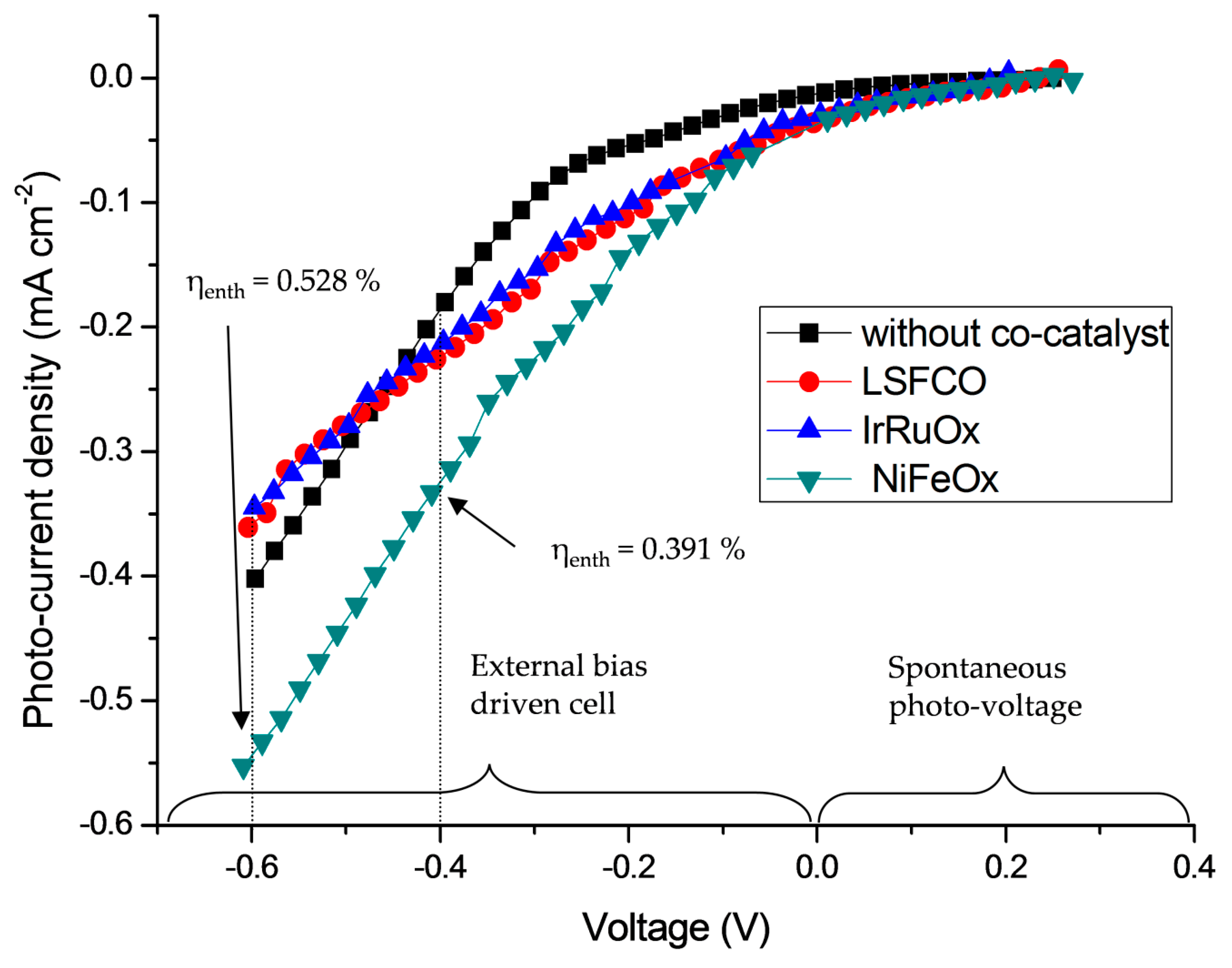
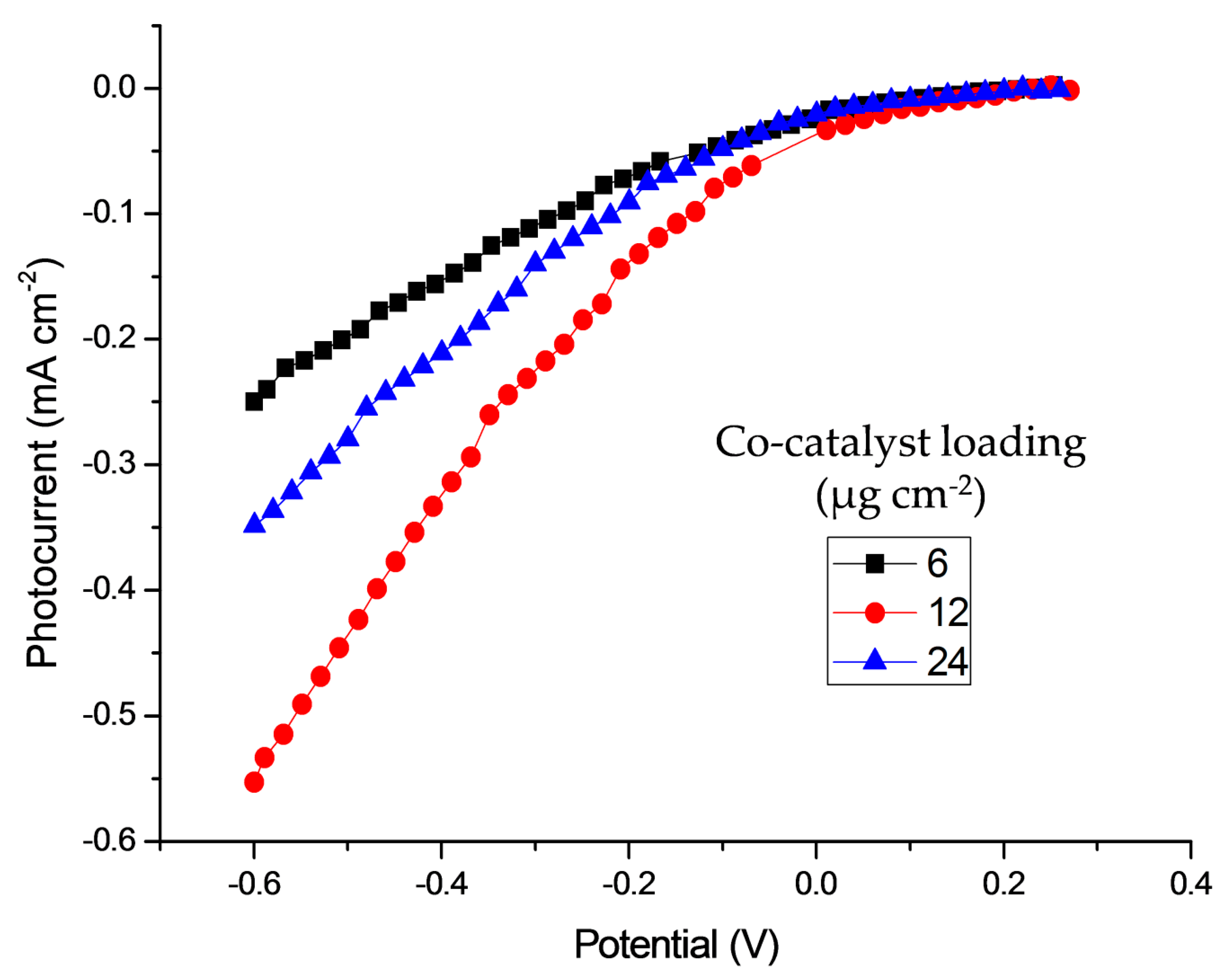
2.2. Photoelectrochemical Characterization

Figure 2 shows the principle of operation of the tandem cell. The hematite photoanode absorbs photons with wavelengths lower than 590 nm according to its energy gap (2.1 eV); the membrane is transparent in the useful wavelength range allowing an efficient irradiation transmission, whereas the CuO photocathode absorbs photons at wavelengths shorter than 1000 nm (1.2 eV). On the right-hand side of Figure 2, an energy diagram for the photoconversion process is shown. Light harvesting generates electron–hole pairs in both electrodes. In the PA, the band edge bending, appearing in the space charge region, drives the photogenerated holes towards the interface (and electrolyte) and the electrons to the external circuit. The reference electrode and counter electrode (RE/CE) are connected to the FTO collector of the photoanode and working electrode, and the sensing electrode (WE/SE) to the photocathode. The valence band levels for Fe2O3 are at a suitable potential to be able to produce oxygen evolution from water. In parallel, the band edge bending in the PC drives the electron towards the electrolyte. The conduction band level, for CuO, is located at a potential low enough to cause the hydrogen evolution reaction.
The photoconversion reactions are reported in Equations (1) and (2), considering an alkaline environment due to a first conditioning of the electrodes in NaOH and to the anionic nature of the membrane:
Anode:
2 OH + 2 h+ → ½ O2 + H2O
Cathode:
2 H2O + 2 e → H2 + 2OH
The phototoconversion activity of the three cell configurations based on the different catalytic enhancers was investigated by depositing the various co-catalysts onto the hematite photoanode. The aim was to improve the oxygen evolution reaction and consequently the water splitting process to enhance the solar to H2 efficiency.
Table 1 summarizes the various PECs obtained by preparing the following assemblies: FTO/photoanode+ionomer+co-catalysts/membrane/photocathode+ionomer/FTO. The ionomer dispersion (FAA3 ION) was deposited on the composite or bare electrodes. The membrane (FAA3-50) and electrode conditioning (0.5 M NaOH 1h) were kept constant, whereas the co-catalysts (NiFeOx, LSFCO, IrRuOx) were added to the FTO/Fe2O3 photoanode. A conditioning of the ionomer and membrane in the alkaline solution before the assembly was necessary in order to exchange from chloride to the active hydroxide ionomer species.
Figure 3 displays the linear sweep voltammetric curves (from the open circuit potential (OCP) to −0.6 V), keeping into account the photocurrent density. This is the difference between the current densities under illumination and in the dark. As a compromise between an enhancement of the catalytic activity at the anode and a proper transparency, 12 µg cm−2 of co-catalyst loading was deposited onto the FTO/Fe2O3+P+Sn and the resulting sample annealed at 450 °C for 1 h in air. A bare PEC cell not containing any co-catalyst was also investigated for comparison. The results are shown in Figure 3. In all the cases where the co-catalysts were added on the photoanode, the onset potential was shifted towards more positive values with respect to the bare PEC but the performance for IrRuOx- and LSFCO-based PEC was very similar to the cell without a co-catalyst addition, especially in the region between −0.4 V and −0.6 V. By using the same promoter of mass loading, the recorded photocurrent (Jlight − Jdark) was higher when the NiFeOx co-catalyst was deposited on the hematite photoanode, with a maximum enthalpy efficiency value (determination is discussed in Section 3.5) of −0.6 V. The most performing cell showed an efficiency of 0.528% in the bias-assisted region (−0.6 V), which was 36.7% larger than the bare PEC without a co-catalyst. It is important to point out that the photocurrent enhancement at mild bias conditions (−0.4 V) was about 50%. This represents a substantial increase.
The polarisation curves under illumination and in the dark for the co-catalysts-based cells reported in Figure 3 are provided in the Supplementary Materials (Figure S2).
As shown in the recent literature [48,49,50,51,52,53,54,55,56,57,58], NiFe-oxide catalysts show outstanding properties for the oxygen evolution reaction in the alkaline environment because of the possibility of a specific tuning of the electronic properties for the adsorption of oxygenated species (e.g., hydroxyl species) and their oxidation [59,60,61,62,63,64,65]. As is well known, it is important in electrocatalysis to modulate the strength of the bonds between the catalyst surface and the adsorbed species. This must not be either strong or too labile. In alkaline solutions, the NiFeOx co-catalyst shows a good compromise compared to the IrRuOx one. IrRuOx forms strong bonds with the hydroxyl species in the alkaline environment, whereas this has optimum characteristics in the acidic environment where the main interaction is with water molecules [43,66]. LSFCO has promising surface properties, but being almost an insulator at low temperatures [45,67], the electron transfer is somewhat impeded.
The lower photoelectrochemical properties of LSFCO and IrRuOx compared with the bare cell at potentials more negative than −0.5 V in the photodiode representation mode may probably be related to a strong adsorption of the hydroxyl species at these potentials. A strong adsorption of hydroxyls may hinder the release of the oxygen molecules. As an example, in conventional electrolysis, due to these strong adsorption characteristics, IrRuOx is less effective in alkaline media compared to acidic environments. In the present case, such characteristics may cause some interference to the photoelectrochemical conversion.
The formation of active Ni1–xFexOOH surface states possibly occurs during the preliminary photoelectrode treatment in KOH and during polarisation (this should in principle occur between 0.4 and 0.5 V vs. reversible hydrogen electrode (RHE) [63,68,69]). If the overpotential at CuO is not very large upon the bias application, the anode experiences potentials between 0 and 1.2 V vs. RHE. We have recorded an increase in the activation effect at high bias potentials, i.e., at more negative cell voltages in the photodiode representation. This evidence points to the formation of the active Ni1–xFexOOH surface states as promoting species. However, it is also important to point out that a small promoting effect also appears at the zero bias.
The hematite photoanode, the NiFeOx co-catalyst dispersion over the hematite and the transparent membrane have been designed to allow that the high wavelength range of the light irradiation can reach the photocathode, thus avoiding that the photocathode limits the behavior of the device. This is confirmed by the results in Figure 3 obtained with the same photocathode and different photoanodes (different co-catalysts). If the photocathode would limit the device performance in the present case [70,71,72], the photocurrent–voltage curves would not be sensitive to the changes in the photoanode.
The loading of the co-catalyst has been optimised, as reported in Figure 4, to achieve a trade-off between the enhancement of the water oxidation process and the need to assure sufficient transparency in the higher wavelength range for light reaching the cathode semiconductor through the transparent membrane. The most appropriate loading for the co-catalyst was 12 µg cm−2 with an enthalpy efficiency of 0.528% in the bias-assisted region at −0.6 V.
Figure 5 shows both the enthalpy and throughput efficiency of the most performing PECs based on the NiFeOx co-catalyst (12 µg cm−2), calculated according to the equations in Section 3.5. The enthalpy efficiency (black line) reached the maximum value in the bias-assisted region between −0.6 V and −0.8 V. The throughput efficiency increased as the bias voltage became larger, due to an enhancement of the overall photocurrent at high bias voltages, as shown in the inset of Figure 5. Photocurrents are similar to those recently reported for advanced core–shell nanostructure-based cells [73]. The throughput efficiency calculation is very similar to the efficiency determination of a conventional (dark) electrolyzer, where the total energy output is divided by the total energy input. The best throughput efficiency recorded at the reversible potential was 1.7%.

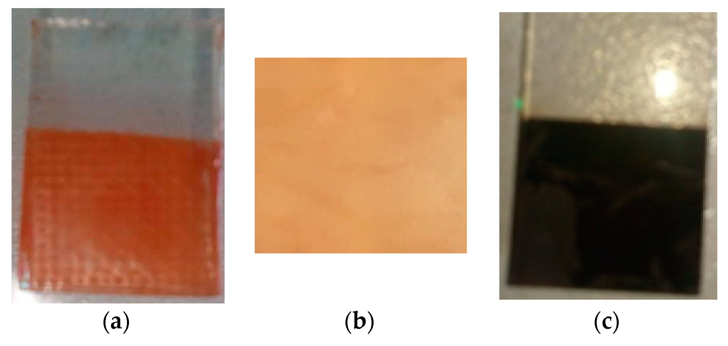
2.3. Morphological Characterisation

SEM images of the most performing photoanode-based PECs were recorded after the polarization measurements and shown at two different magnifications in Figure 6a,b. At a higher magnification (Figure 6b), the Fe2O3 nanocolumns are visible in grey, whereas the NiFeOx co-catalyst is located as agglomerates of round nanoparticles in some regions and are highlighted as white particles in the low magnification image as identified by the energy dispersive analysis (EDX). The EDX analysis is reported in Figure S3 (Supplementary Materials). The arrows in the high-magnification micrograph indicate co-catalyst clusters corresponding to the bright particles in the low-magnification image. The homogeneous ionomer coating over the photoanode forms a patina-like layer that attenuates the contours of the hematite nanorods.
The overall photoanode structure is thus consisting of three components with specific roles, i.e., the semiconducting hematite photoanode for light harvesting and charge separation through the space charge layer, the NiFeOx co-catalyst, addressing the enhancement of the oxygen evolution kinetics at the interface and the hydrophilic ionomer to form an extended polymer electrolyte region at the interface and provide the reacting species (water molecules). Of course, the morphology of this composite structure can be further improved to favour a better interface and distribution of the components; however, the present configuration gives evidence of an enhanced water splitting in a complete cell device of practical interest.

3. Materials and Methods

3.1. Synthesis of Photoelectrodes

3.1.1. Synthesis of (110) Oriented Hematite Nanorods

The deposition of nanocolumns synthesized by a hydrothermal bath deposition is one of the most widespread procedures for the fabrication of hematite electrodes [74]. Different synthetic conditions have been explored based on a literature review analyzing the photoresponses of the resulting hematite films.
The following synthetic procedure was selected for achieving the maximum photocurrent and minimizing the use of material and energy resources: vertically aligned FTOs, with adhesive tape on one side (to permit the electric contact), were placed in a closed glass reactor containing an aqueous solution consisting of 0.15 M FeCl3 and 1 M NaNO3. A chemical bath deposition was obtained by heating the reactor at 100 °C for 6 h. Afterwards, the electrodes were washed with water and dried at room temperature and the formation of FeOOH/FTO was achieved. Thus, the electrode was thermally annealed at 650 °C for 1 h in air in order to obtain α-Fe2O3/FTO.

3.1.2. Hematite Modification with Tin and Phosphorus

The Sn modification of hematite consisted of placing the hematite/FTO electrodes in an oven at 750 °C for 15 min. After that, the electrodes were cooled down to room temperature. The modification with P was achieved by dip-coating the Sn-modified electrodes in a 0.1 mol·L−1 NH4NaHPO4 (99%, Sigma-Aldrich, St. Louis, MI, USA) aqueous solution. The electrode was kept in the solution for 1 min using rates for both immersion and withdrawal of 450 mm/min. The coated electrodes were dried at 100 °C for 30 min and then they were thermally annealed at 450 °C for 30 min in air.
The occurrence of P and Sn doping in the final photoanodes was confirmed by an EDX analysis (Figure S3 in Supplementary Materials).

3.1.3. Synthesis of Cupric Oxide

The optimized copper oxide procedure is based on some previous works [12,75] and detailed as reported: an electrochemical bath was composed by a 0.1 M Cu(NO3)2 and 3 M lactic acid aqueous solution adjusted to pH 5 with NaOH. The FTO substrate, with an adhesive tape on one side, was placed as a working and sensing electrode and a Pt wire as a counter electrode. The electrodeposition was performed at −0.3 V vs. an Ag/AgCl (3M) reference electrode for 1 h with the consequent formation of Cu/FTO. Thus, a chemical oxidation was performed by immersing for 3 min Cu/FTO in a 0.125 M (NH4)2S2O8 and 2.5 M NaOH aqueous solution. The electrode was washed with water and ethanol and Cu(OH)2/FTO was obtained. Finally, CuO/FTO was achieved by a thermal treatment of the electrodes at 450 °C for 1 h in air.

3.1.4. Synthesis of co-Catalysts

The NiFeOx co-catalyst was prepared according to the synthetic procedure referred to as the oxalate method [76]. Ni and Fe nitrates were dissolved in distilled water and mixed with a solution of oxalic acid neutralized at pH 6.5 with NaOH. The molar ratio between the chelating agent and the metal was 10. A complex was formed and then treated at 80 °C with H2O2 in order to obtain a precipitate. After filtering, washing and drying at 100 °C for 24 h, the powder was then calcined at 350 °C for 120 min with the subsequent formation of NiFeOx. The formed oxide was characterized in terms of the chemical and structure properties. In order to investigate the behavior of the cost-effective NiFeOx catalytic enhancer, the benchmark IrRuOx and LSFCO catalysts for the alkaline environment were also used.
The IrRuOx electrocatalyst was synthesized by a modified Adams fusion method [77]. The metal precursors (IrCl4·xH2O or RuCl3·xH2O, StremChemicals, Newburyport, MA, USA) were added to isopropanol to obtain a total metal concentration of 0.08 M. This solution was magnetically stirred at room temperature for 1 h to ensure the complete dissolution of the precursors, followed by the addition of NaNO3, previously ground. The slurry was heated at 90 °C in air until becoming completely dry. The dry salt was then placed in a furnace and treated at 500 °C for 30 min. The oxide formed from the fused salts was washed with distilled water to remove the excess of salts, filtered and dried in an oven at 80 °C overnight. To completely remove the sodium impurities, a pre-leaching procedure in HClO4 (0.1 M, 80 °C, 1 h) was adopted.
The commercial LSFCO (La0.6Sr0.4Fe0.8CoO3) was purchased from the Praxair company (Manchester, CT, United States). The catalytic inks were prepared by sonicating for half an hour the co-catalyst powder with 2-propanol in order to obtain a 2 mg mL−1 dispersion. After that, 12 µg cm−2 co-catalyst loadings were collected and deposited onto the doped FTO/Fe2O3 electrode with a doctor blade technique. Thus, the electrodes were subjected to the same heat treatment used for the modification with P (450 °C for 1 h) before the ionomer deposition.

3.1.5. Membrane and Ionomer

An FAA-3-50 (50 mm thickness) membrane was used after the ion exchange in KOH [78]. This membrane thickness was selected as a trade-off between low resistance and proper mechanical handling. The conductivity of this 50 µm membrane [78] is sufficiently high to keep ohmic losses associated with ion transport in the polymer electrolyte separator within 1 mV in the range of the recorded current densities. The ionomer dispersion was prepared by solubilizing the received solid ionomer powder (FAA3-shredded film) in a mixture of solvents. An alcoholic solution of n-propanol and ethanol (1:1 wt) was used for this purpose and the FAA3 ionomer was solubilized at room temperature under stirring to have a ~5 wt % dispersion.

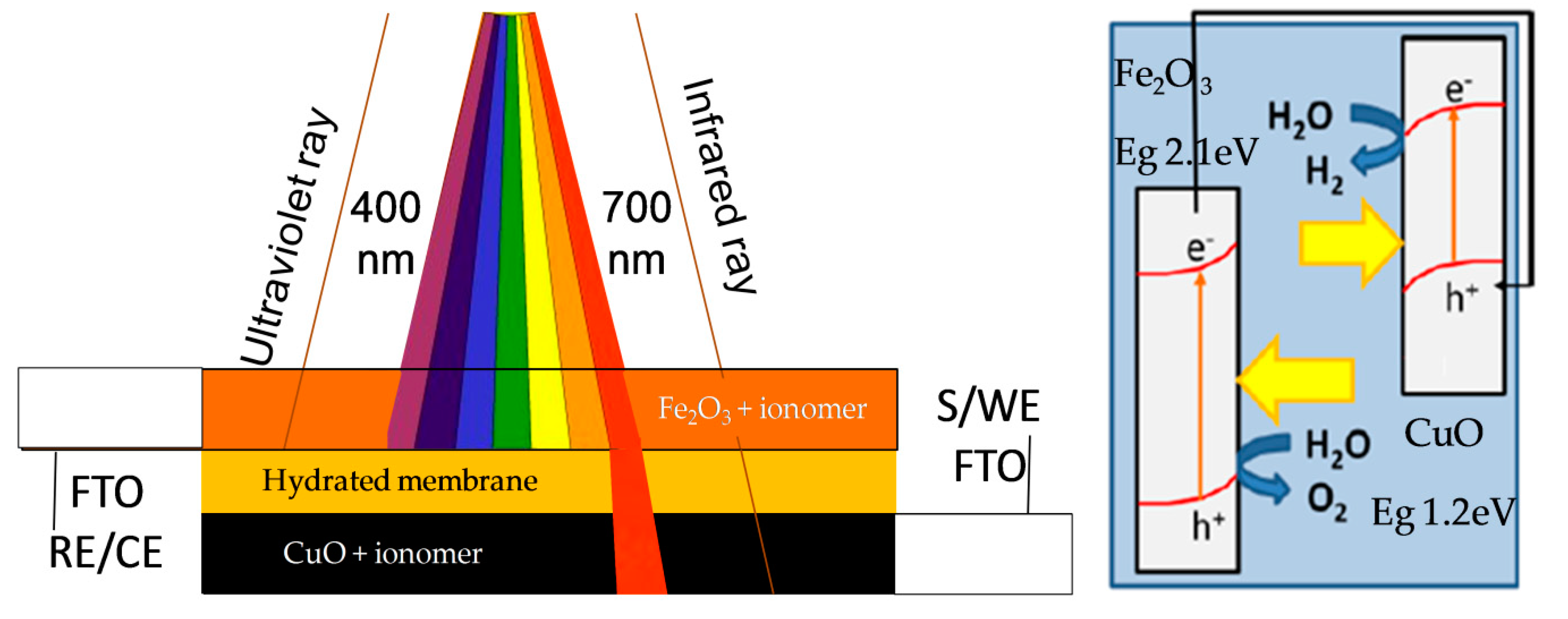
3.2. Assembly of the Cell

In the assembled cell, the photoelectrodes had an area of 1 × 1 cm2. A Fumasep membrane (FumaTech, Bietigheim-Bissingen, Germany), based on a polysulfone backbone with quaternary ammonium side chain groups provided in the bromide form, was first treated in NaCl for 72 h and then was subjected to an anion exchange process in a 0.5 M NaOH aqueous solution for 24 h before assembly. The polymeric membrane area was about 1.1 × 1.1 cm2. The ionomer dispersion, made of the same polymer formulation of the membrane, was deposited on the electrode surface to extend the interfacial region, to favour adhesion to the membrane and to increase the stability of the photoelectrodes. PA, PC and the hydrated membrane were thus brought into contact according to the following arrangement: photoanode/ionomer/membrane/ionomer/photocathode. The water will be kept inside the cell by the hydrated membrane and by adding a drop of water in the active area of photoelectrodes before assembly. The backing side of the hematite electrode was covered with black insulating tape, with a central hole with a well-defined area of 0.25 cm2. The electrodes and membrane used for the selected tandem configuration before the cell assembly are shown in Figure 7.
Finally, two clamps located at each side of the cell were used to secure and keep pressed the overall device. The device was placed in a sample holder (horizontal or vertical) and illuminated from the hematite electrode glass substrate thanks to a solar simulator (Oriel in the horizontal configuration or Osram in the vertical configuration) to provide an incident power density for the light irradiation depending on the solar simulator and the specific arrangement of the cell set-up. In the experiments with the solar simulator reported here, the cell was placed horizontally and illuminated by the solar simulator from the FTO photoanode back contact by an incident power density of 92 mW cm−2, as measured using a calibrated photovoltaic cell.
The hematite photoanode was investigated with or without co-catalysts together with the copper oxide photocathode for “water splitting” in the tandem cell.

3.3. Physicochemical Characterization

X-ray diffraction (XRD) patterns for powder catalysts were recorded with an X’Pert 3710 X-Ray (Philips, Eindhoven, Netherlands) diffractometer using a Cu-Kα source operating at 40 kV and 20 mA. The peak profiles of the X-ray reflections were obtained by applying the Marquardt algorithm to calculate the crystallite size by the Debye–Scherrer equation. The instrumental broadening was determined by using a standard platinum sample.
The transmission electron microscopy (TEM) analysis was made by first dispersing the catalyst powder (NiFeOx or IrRuOx or LSFCO) in isopropyl alcohol. A few drops of these suspensions were deposited on carbon film-coated Cu grids and analyzed with a CM12 microscope (FEI, Eindhoven, The Netherlands).
The morphology of the most performing photoanode was studied by scanning electron microscopy (SEM) with an FEI-XL 30 SEM microscope (Hillsboro, OR, USA).

3.4. Electrochemical Tests

The light source in the photoelectrochemical measurement was about 1 sun illumination according to the specific arrangement used (92 mW cm−2) and the cell was illuminated either in the horizontal or vertical mode according to the type of experiment planned. According to the main characteristics, a down-selection of the most promising formulations and synthesis procedures for the cell components was carried out.
Polarization tests were carried out by sweeping the potential between the open circuit potential (OCP) value up to a bias of −1.5 V. Some graphs were reported in the region of interest (avoiding drastic conditions for degradation) up to −0.6 V (bias-controlled region) and recording the current density of the PEC was first in the dark and thereafter under illumination. The sign of the recorded photocurrent and the potential bias are reported as negative (reverse current and applied bias) as in the case of the photodiode mode. When a spontaneous photovoltage is recorded, this takes the positive sign like in a photodiode. The photocurrent measured between the OCP and the short circuit (i.e., 0 V) is driven by the illumination only (spontaneous photocurrent), and in this region the potential is positive. On the other hand, in the negative potential region, an external bias-assisted photocurrent occurs.
The registration of the H2 ionic current at the cathode outlet of a specifically designed 4 cm2 tandem photoelectrolysis cell was carried out using a mass spectrometer (ThermoStar™ GSD320), under dark and light conditions (Figure S4).
A short-term durability test was carried out to preliminarily validate the photoelectrolysis cell stability. In this experiment, the cell was fully immersed in water (to allow for proper hydration without the need to refill water) and illuminated by a solar lamp (Figure S5).

3.5. Efficiency of the PEC

The ranges of the wavelengths of the solar spectrum that are in theory absorbed by the photoanode and photocathode along with the fraction of wavelengths in the near infrared region that are not absorbed by this tandem cell are shown in Figure S6 (Supplementary Materials). Accordingly, it is observed that both hematite and CuO contribute to the conversion efficiency to a relevant extent, being that their respective fractions of absorbed light are very similar.
The efficiency of the complete cell represents an important parameter to drive the selection of the materials and components. Both enthalpy and Gibbs energy-based efficiency are determined from the ratio between the net power output and the power of incident light. The net power output in the case of a spontaneous photovoltage-assisted process is determined from the photocurrent multiplied by the reversible potential, which is 1.229 V in the case of the Gibbs energy-based efficiency or multiplied by the thermoneutral potential, 1.48 V. In the case of the enthalpy efficiency, the latter corresponds to the hydrogen production rate multiplied by the standard enthalpy of combustion (high heating value (HHV)) assuming a faradaic efficiency of 100%. The Gibbs energy-based efficiency does not take into consideration as a useful product the reversible heat (TΔS) associated with the combustion of the produced hydrogen and oxygen, e.g., in a combined heat and power unit. In other words, the Gibbs energy efficiency is based on the useful work and not on the total energy (reaction enthalpy).
Otherwise, in the case of applying an external bias, the “net power output” is the difference between the maximum or total electric power available from the H2 produced and the power supplied by the external source. Beside these methods, to compare the efficiency of the photoelectrolysis cells to that of conventional electrolyzers [79,80] combined to photovoltaic plants, the efficiency can also be defined as the ratio between the power output (HHV of the produced hydrogen per unit of time) and the overall power input (solar + electric) supplied by an external source. This is usually reported as “throughput efficiency”. Accordingly, different solar-to-hydrogen efficiency definitions are used in this field. These are reported below in Equations (3)–(5), assuming a 100% faradaic efficiency for hydrogen generation and used accordingly to provide a complete picture:
Enthalpy efficiency:
η = Ip × (ΔH/nF − |Ebias|)/Pin = Ip × (Etn − |Ebias|)/Pin
Gibbs energy efficiency:
η = Ip × (ΔG/nF − |Ebias|)/Pin = Ip × (Erev − |Ebias|)/Pin
Throughput efficiency:
η = Ip × (ΔH/nF)/(Pin + Ip × |Ebias|) = Ip × Etn/(Pin + Ip × |Ebias|)
where Etn = 1.48 V, Erev = 1.23 V, Ebias ≡ V, Pin ≡ mW cm−2, and Ip = I light − I dark ≡ mA cm−2.

4. Conclusions

Photoelectrochemical cells (PECs), based on a solid electrolyte membrane separating the Fe2O3-based photoanode and CuO-based photocathode, were investigated in order to increase the solar to hydrogen efficiency. The concept of tandem cells shows how to capture a significant portion of the incident solar spectrum and it is based on the choice of semiconductors with appropriate energy band gaps. The oxygen evolution reaction, occurring at the photoanode, represents the rate determining step of the entire photoelectrochemical water splitting. Thus, the effect of different co-catalysts on the performance of hematite electrodes with suitable mass loading (12 µg cm−2) was studied. The addition of NiFeOx to the hematite photoelectrode allowed to improve the performance of the cost-effective PECs compared with IrRuOx and LSFCO, the benchmark co-catalysts. The maximum value for the enthalpy efficiency was 0.53%, recorded in the bias-assisted region (−0.6 V), whereas a value of 1.7 % was achieved for the throughput efficiency at the reversible potential bias, assuming a 100% faradaic efficiency for hydrogen generation.

Supplementary Materials

The following are available online at https://www.mdpi.com/2073-4344/10/5/525/s1, Figure S1: XRD pattern for a hematite/FTO electrode calcined at 650 °C for 1 h, Figure S2: Polarisation curves in an extended window under illumination and in the dark for the co-catalyst-based cells reported in Figure 3, Figure S3: EDX analysis of the outer NiFeOx-coated hematite photoanode surface, Figure S4: Registration of H2 ionic current at the cathode outlet of a specifically designed 4 cm2 tandem photoelectrolysis cell using a mass spectrometer, under dark and light conditions, Figure S5: Short-term durability study of a tandem 0.25 cm2 photoelectrolysis cell fully immersed in water and illuminated by a solar lamp, Figure S6: AM1.5 spectrum utilisation by 2.1 eV bandgap of doped Fe2O3 (blue shading) and by 1.2 eV bandgap CuO underneath (green shading).

Author Contributions

Conceptualization, R.G. and A.S.A.; methodology, A.S.A., R.G., V.B.; synthesis, M.I.D.G., M.C., S.C.Z.; investigation, C.L.V., S.T., A.C.; data curation, C.L.V. and S.T.; writing—original draft preparation, C.L.V., M.I.D.G.; writing—review and editing, V.B., A.C., A.S.A., R.G. All authors have read and agreed to the published version of the manuscript.

Funding

Authors gratefully acknowledge funding from the European Union’s Horizon 2020 research and innovation programme under grant agreement no. 760930 (FotoH2 project).

Conflicts of Interest

The authors declare no conflict of interest.

References

  1. Gratzel, M. Photoelectrochemical cells. Nature 2001, 414, 338–344. [Google Scholar] [CrossRef] [PubMed]
  2. Khaselev, O.; Turner, J.A. A monolithic photovoltaic-photoelectrochemical device for hydrogen production via water splitting. Science 1998, 280, 425–428. [Google Scholar] [CrossRef] [PubMed]
  3. Bak, T.; Nowotny, J.; Rekas, M.; Sorrell, C.C. Photo-electrochemical hydrogen generation from water using solar energy. Materials-related aspects. Int. J. Hydrogen Energy 2002, 27, 991–1022. [Google Scholar] [CrossRef]
  4. Fujishima, A.; Honda, K. Electrochemical photolysis of water at a semiconductor electrode. Nature 1972, 238, 37–38. [Google Scholar] [CrossRef] [PubMed]
  5. Passalacqua, R.; Perathoner, S.; Centi, G. Semiconductor, molecular and hybrid systems for photoelectrochemical solar fuel production. J. Energy Chem. 2017, 26, 219–240. [Google Scholar] [CrossRef]
  6. Jing, S.; Yin, D.S.; Lu, J.; Shen, P.K.; Tsiakaras, P. P-doped CNTs encapsulated nickel hybrids with flower-like structure as efficient catalysts for hydrogen evolution reaction. Electrochim. Acta 2019, 298, 6582–6591. [Google Scholar] [CrossRef]
  7. Grądzka, I.; Gierszewski, M.; Ziółek, M. The effect of chloride anions on charge transfer in dye-sensitized photoanodes for water splitting. Biomimetics 2019, 4, 5. [Google Scholar] [CrossRef] [Green Version]
  8. Sim, Y.; John, J.; Moon, J.; Sim, U. Photo-assisted hydrogen evolution with reduced graphene oxide catalyst on silicon nanowire photocathode. Appl. Sci. 2018, 8, 2046. [Google Scholar] [CrossRef] [Green Version]
  9. Cots, A.; Bonete, P.; Sebastian, D.; Baglio, V.; Aricò, A.S.; Gomez, R. Toward tandem solar cells for water splitting using polymer electrolytes. ACS Appl. Mater. Interfaces 2018, 10, 25393–25400. [Google Scholar] [CrossRef]
  10. Prevot, M.S.; Sivula, K. Photoelectrochemical tandem cells for solar water splitting. J. Phys. Chem. C 2013, 117, 17879–17893. [Google Scholar] [CrossRef]
  11. Chiam, S.Y.; Kumar, M.H.; Bassi, P.S.; Seng, H.L.; Barber, J.; Wong, L.H. Improving the efficiency of hematite nanorods for photoelectrochemical water splitting by doping with manganese. ACS Appl. Mater. Interfaces 2014, 6, 5852–5859. [Google Scholar] [CrossRef]
  12. Hsu, Y.-K.; Yu, C.-H.; Lin, H.-H.; Chen, Y.-C.; Lin, Y.-G. Template synthesis of copper oxide nanowires for photoelectrochemical hydrogen generation. J. Electroanal. Chem. 2013, 704, 19–23. [Google Scholar] [CrossRef]
  13. Sivula, K.; Le Formal, F.; Grätzel, M. Solar water splitting: Progress using hematite (α-Fe2O3) photoelectrodes. Chemsuschem 2011, 4, 432–449. [Google Scholar] [CrossRef] [PubMed]
  14. Cots, A.; Bonete, P.; Gomez, R. Improving the stability and efficiency of CuO photocathodes for solar hydrogen production through modification with iron. ACS Appl. Mater. Interfaces 2018, 10, 26348–26356. [Google Scholar] [CrossRef] [PubMed] [Green Version]
  15. Wang, D.; Lu, J.; Luo, L.; Jing, S.; Abbo, H.S.; Titinchi, S.J.J.; Chen, Z.; Tsiakaras, P.; Yin, S. Enhanced hydrogen evolution activity over microwave-assisted functionalized 3D structured graphene anchoring FeP nanoparticles. Electrochim. Acta 2019, 317, 242–249. [Google Scholar] [CrossRef]
  16. Vasilaki, E.; Vernardou, D.; Kenanakis, G.; Vamvakaki, M.; Katsarakis, N. TiO2/WO3 photoactive bilayers in the UV–Vis light region. Appl. Phys. A 2017, 123, 231–238. [Google Scholar] [CrossRef]
  17. Vasilaki, E.; Georgaki, I.; Vernardou, D.; Vamvakaki, M.; Katsarakis, N. Ag-loaded TiO2/reduced graphene oxide nanocomposites for enhanced visible-light photocatalytic activity. Appl. Surf. Sci. 2015, 353, 865–872. [Google Scholar] [CrossRef]
  18. Hernàndez, S.; Saracco, G.; Barbero, G.; Alexe-Ionescu, A.L. Role of the electrode morphology on the optimal thickness of BiVO4 anodes for photoelectrochemical water splitting cells. J. Electroanal. Chem. 2017, 799, 481–486. [Google Scholar] [CrossRef]
  19. Valerini, D.; Hernàndez, S.; di Benedetto, F.; Russo, N.; Saracco, G. Sputtered WO3 films for water splitting applications. Mater. Sci. Semicond. Proc. 2016, 42, 150–154. [Google Scholar] [CrossRef]
  20. Peng, B.; Xia, M.; Li, C.; Yue, C.; Diao, P. Network Structured CuWO4/BiVO4/Co-Pi Nanocomposite for Solar Water Splitting. Catalysts 2018, 8, 663. [Google Scholar] [CrossRef] [Green Version]
  21. Sharma, P.; Jang, J.-W.; Lee, J.S. Key strategies to advance the photoelectrochemical water splitting performance of α-Fe2O3 photoanode. Chemcatchem 2019, 11, 157–179. [Google Scholar] [CrossRef]
  22. Xi, L.; Lange, K.M. Surface modification of hematite photoanodes for improvement of photoelectrochemical performance. Catalysts 2018, 8, 497. [Google Scholar] [CrossRef] [Green Version]
  23. Wu, D.; Zhang, Z. Simultaneous non-metal doping and cocatalyst decoration for efficient photoelectrochemical water splitting on hematite photoanodes. Electrochim. Acta 2018, 282, 48–55. [Google Scholar] [CrossRef]
  24. Zhu, Q.; Yu, C.; Zhang, X. Ti, Zn co-doped hematite photoanode for solar driven photoelectrochemical water oxidation. J. Energy Chem. 2019, 35, 30–36. [Google Scholar] [CrossRef] [Green Version]
  25. Zhang, Y.; Jiang, S.; Song, W.; Zhou, P.; Ji, H.; Ma, W.; Hao, W.; Chen, C.; Zhao, J. Nonmetal P-doped hematite photoanode with enhanced electron mobility and high water oxidation activity. Energy Environ. Sci. 2015, 8, 1231–1236. [Google Scholar] [CrossRef]
  26. Liu, T.; Chen, W.; Liu, X.; Zhu, J.; Lu, L. Well-dispersed ultrafine nitrogen-doped TiO2 with polyvinylpyrrolidone (PVP) acted as N-source and stabilizer for water splitting. J. Energy Chem. 2016, 25, 1–9. [Google Scholar] [CrossRef]
  27. Buller, S.; Strunk, J. Nanostructure in energy conversion. J. Energy Chem. 2016, 25, 171–190. [Google Scholar] [CrossRef]
  28. Le Formal, F.; Sivula, K.; Gratzel, M. The transient photocurrent and photovoltage behavior of a hematite photoanode under working conditions and the influence of surface treatments. J. Phys. Chem. C. 2012, 116, 26707–26720. [Google Scholar] [CrossRef]
  29. Kim, J.Y.; Magesh, G.; Youn, D.H.; Jang, J.-W.; Kubota, J.; Domen, K.; Domen, K.; Lee, J.S. Single-crystalline, wormlike hematite photoanodes for efficient solar water splitting. Sci. Rep. 2013, 3, 2681–2689. [Google Scholar] [CrossRef] [Green Version]
  30. Malara, F.; Minguzzi, A.; Marelli, M.; Morandi, S.; Psaro, R.; Santo, V.D.; Naldoni, A. α-Fe2O3/NiOOH: An effective heterostructure for photoelectrochemical water oxidation. ACS Catal. 2015, 5, 5292–5300. [Google Scholar] [CrossRef]
  31. Zhou, L.; Shao, M.; Wei, M.; Duan, X. Advances in efficient electrocatalysts based on layered double hydroxides and their derivatives. J. Energy Chem. 2017, 26, 1094–1106. [Google Scholar] [CrossRef] [Green Version]
  32. Kment, Š.; Sivula, K.; Naldoni, A.; Sarmah, S.P.; Kmentovà, H.; Kulkarni, M.; Rambabu, Y.; Schmuki, P.; Zbořil, R. FeO-based nanostructures and nanohybrids for photoelectrochemical water splitting. Prog. Mater. Sci. 2020, 110, 100632. [Google Scholar] [CrossRef]
  33. Maeda, K.; Higashi, M.; Siritanaratkul, B.; Abe, R.; Domen, K. SrNbO2N as a water-splitting photoanode with a wide visible-light absorption band. J. Am. Chem. Soc. 2011, 133, 12334–12337. [Google Scholar] [CrossRef] [PubMed]
  34. Surendranath, Y.; Kanan, M.W.; Nocera, D.G. Mechanistic studies of the oxygen evolution reaction by a cobalt-phosphate catalyst at neutral pH. J. Am. Chem. Soc. 2010, 132, 16501–16509. [Google Scholar] [CrossRef] [PubMed]
  35. Xi, L.; Tran, P.D.; Chiam, S.Y.; Bassi, P.S.; Mak, W.F.; Mulmudi, H.K.; Batabyal, S.K.; Barber, J.; Loo, J.S.C.; Wong, L.H. Co3O4-Decorated Hematite Nanorods As an Effective Photoanode for Solar Water Oxidation. Phys. Chem. C 2012, 116, 13884–13889. [Google Scholar] [CrossRef]
  36. European Commission. Communication from the Commission to the European Parliament, the Council, the European Economic and Social Committee and the Committee of the Regions on the 2017 List of Critical Raw Material for the Eu; Document 52017DC0490; European Commission: Brussels, Belgium, 2017; pp. 1–8. Available online: https://eur-lex.europa.eu/legal-content/EN/TXT/DOC/?uri=CELEX:52017DC0490&from=EN (accessed on 1 May 2020).
  37. Yang, J.; Wang, D.; Han, H.; Li, C. Roles of cocatalyst in photocatalysis and photoelectrocatalysis. Acc. Chem. Res. 2013, 46, 1900–1909. [Google Scholar] [CrossRef]
  38. Wang, D.; Li, R.; Shi, J.Z.J.; Han, J.; Zong, X.; Li, C. Photocatalytic water oxidation on BiVO4 with the electrocatalyst as an oxidation cocatalyst: Essential relations between electrocatalyst and photocatalyst. J. Phys. Chem. C 2012, 116, 5082–5089. [Google Scholar] [CrossRef]
  39. Ding, C.; Shi, J.; Wang, Z.; Li, C. Photoelectrocatalytic water splitting: Significance of cocatalysts, electrolyte, and interfaces. ACS Catal. 2016, 7, 675–688. [Google Scholar] [CrossRef]
  40. Li, D.; Shi, J.; Li, C. Transition-metal-based electrocatalysts as cocatalysts for photoelectrochemical water splitting: A mini review. Small 2018, 14, 1704179–1704201. [Google Scholar] [CrossRef]
  41. Maitani, M.M.; Yamada, T.; Mashiko, H.; Yoshimatsu, K.; Oshima, T.; Ohtomo, A.; Wada, Y. Microwave Effects on Co–Pi cocatalysts deposited on α-Fe2O3 for application to photocatalytic oxygen evolution. ACS Appl. Mater. Interfaces 2017, 9, 10349–10354. [Google Scholar] [CrossRef]
  42. Duan, S.-F.; Geng, Y.-Y.; Pan, X.-B.; Yao, X.-Q.; Zhao, Y.-X.; Li, X.; Tao, C.-L.; Qin, D.-D. Tubular morphology preservation and doping engineering of Sn/P-codoped hematite for photoelectrochemical water oxidation. Dalton Trans. 2019, 48, 928–936. [Google Scholar] [CrossRef] [PubMed]
  43. Siracusano, S.; van DiJk, N.; Payne-Johnson, E.; Baglio, V.; Aricò, A.S. Nanosized IrOx and IrRuOx electrocatalysts for the O2 evolution reaction in PEM water electrolysers. Appl. Catal. B 2015, 164, 488–495. [Google Scholar] [CrossRef]
  44. Siracusano, S.; Trocino, S.; Briguglio, N.; Baglio, V.; Aricò, A.S. Electrochemical impedance spectroscopy as a diagnostic tool in polymer electrolyte membrane electrolysis. Materials 2018, 11, 1368. [Google Scholar] [CrossRef] [PubMed] [Green Version]
  45. Alegre, C.; Modica, E.; Aricò, A.S.; Baglio, V. Bifunctional oxygen electrode based on a perovskite/carbon composite for electrochemical devices. J. Electroanal. Chem. 2018, 808, 412–419. [Google Scholar] [CrossRef]
  46. Aricò, A.S.; Girolamo, M.; Siracusano, S.; Sebastian, D.; Baglio, V.; Schuster, M. Polymer electrolyte membranes for water photo-electrolysis. Membranes 2017, 7, 25. [Google Scholar] [CrossRef] [Green Version]
  47. Gatto, I.; Stassi, A.; Baglio, V.; Carbone, A.; Passalacqua, E.; Aricò, A.S.; Schuster, M.; Bauer, B. Optimization of perfluorosulphonic ionomer amount in gas diffusion electrodes for PEMFC operation under automotive conditions. Electrochim. Acta 2015, 165, 450–455. [Google Scholar] [CrossRef]
  48. Bandal, H.; Jadhav, V.H.; Kim, H. Facile synthesis of bicontinuous Ni3Fe alloy for efficient electrocatalytic oxygen evolution reaction. J. Alloy. Compd. 2017, 726, 875–884. [Google Scholar] [CrossRef]
  49. Gil, G.-J.H.B.-M.; Ryu, C.-H. Preparation of the electrode using NiFe2O4 powder for the alkaline water electrolysis. J. Ind. Eng. Chem. 2017, 48, 242–248. [Google Scholar] [CrossRef]
  50. McCrory, C.C.L.; Jung, S.; Peters, J.C.; Jaramillo, T.F. Benchmarking Heterogeneous Electrocatalysts for the Oxygen Evolution Reaction. J. Am. Chem. Soc. 2013, 135, 16977–16987. [Google Scholar] [CrossRef]
  51. Gong, M.; Dai, H. A mini review of NiFe-based materials as highly active oxygen evolution reaction electrocatalysts. Nano Res. 2014, 8, 23–39. [Google Scholar] [CrossRef] [Green Version]
  52. Huang, L.; Ge, X.; Dong, S. A facile conversion of a Ni/Fe coordination polymer to a robust electrocatalyst for the oxygen evolution reaction. RSC Adv. 2017, 7, 32819–32825. [Google Scholar] [CrossRef] [Green Version]
  53. Fan, H.; Chen, W.; Chen, G.; Huang, J.; Song, C.; Du, Y.; Li, C.; Ostrikov, K.K. Plasma-heteroatom-doped Ni-V-Fe trimetallic phospho-nitride as high-performance bifunctional electrocatalyst. Appl. Catal. B Environ. 2019, 268, 118440. [Google Scholar] [CrossRef]
  54. Qin, F.; Zhao, Z.; Alam, K.; Ni, Y.; Hernandez, F.C.R.; Yu, L.; Chen, S.; Ren, Z.; Wang, Z.; Bao, J. Trimetallic NiFeMo for Overall Electrochemical Water Splitting with a Low Cell Voltage. ACS Energy Lett. 2018, 3, 546–554. [Google Scholar] [CrossRef]
  55. Pebley, A.; Decolvenaere, E.; Pollock, T.; Gordon, M. Oxygen evolution on Fe-doped NiO electrocatalysts deposited: Via microplasma. Nanoscale 2017, 9, 15070–15082. [Google Scholar] [CrossRef]
  56. Paulraj, A.R.; Kiros, Y.; Göthelid, M.; Johansson, M.B. NiFeOx as a bifunctional electrocatalyst for oxygen reduction (OR) and evolution (OE) reaction in alkaline media. Catalysts 2018, 8, 328. [Google Scholar] [CrossRef] [Green Version]
  57. Jiang, J.; Zhang, C.; Ai, L. Hierarchical iron nickel oxide architectures derived from metal-organic frameworks as efficient electrocatalysts for oxygen evolution reaction. Electrochim. Acta 2016, 208, 17–24. [Google Scholar] [CrossRef]
  58. Fang, J.; Hu, L.; Wang, M.; Gan, L.; Chen, C.; Jiang, Y.; Xiao, B.; Lai, Y.; Li, J. NiO-Fe2O3/carbon nanotubes composite as bifunctional electrocatalyst for rechargeable Zn-air batteries. Mater. Lett. 2018, 218, 36–39. [Google Scholar] [CrossRef]
  59. Dionigi, F.; Strasser, P. NiFe-Based (Oxy)hydroxide catalysts for oxygen evolution reaction in non-acidic electrolytes. Adv. Energy Mater. 2016, 6, 1600621. [Google Scholar] [CrossRef]
  60. Pérez-Alonso, F.; Adán, C.; Rojas, S.; Peña, M.A.; Jose, F. Ni/Fe electrodes prepared by electrodeposition method over different substrates for oxygen evolution reaction in alkaline medium. Int. J. Hydrogen Energy 2014, 39, 5204–5212. [Google Scholar] [CrossRef]
  61. Yang, Y.; Dang, L.; Shearer, M.; Sheng, H.; Li, W.; Chen, J.; Xiao, P.; Zhang, Y.; Hamers, R.J.; Jin, S. Highly Active Trimetallic NiFeCr Layered Double Hydroxide Electrocatalysts for Oxygen Evolution Reaction. Adv. Energy Mater. 2018, 8, 1703189. [Google Scholar] [CrossRef]
  62. Friebel, D.; Louie, M.W.; Bajdich, M.; Sanwald, K.E.; Cai, Y.; Wise, A.M.; Cheng, M.J.; Sokaras, D.; Weng, T.C.; Alonso-Mori, R.; et al. Identification of highly active Fe sites in (Ni,Fe)OOH for electrocatalytic water splitting. J. Am. Chem. Soc. 2015, 137, 1305–1313. [Google Scholar] [CrossRef] [Green Version]
  63. Landon, J.; Demeter, E.; Inoǧlu, N.; Keturakis, C.; Wachs, I.E.; Vasić, R.; Frenkel, A.I.; Kitchin, J.R. Spectroscopic characterization of mixed Fe-Ni oxide electrocatalysts for the oxygen evolution reaction in alkaline electrolytes. ACS Catal. 2012, 2, 1793–1801. [Google Scholar] [CrossRef]
  64. Fominykh, K.; Chernev, P.; Zaharieva, I.; Sicklinger, J.; Stefanic, G.; Döblinger, M.; Müller, A.; Pokharel, A.; Böcklein, S.; Scheu, C.; et al. Iron-doped nickel oxide nanocrystals as highly efficient electrocatalysts for alkaline water splitting. ACS Nano 2015, 9, 5180–5188. [Google Scholar] [CrossRef] [PubMed]
  65. Liu, J.; Zhu, D.; Ling, T.; Vasileff, A.; Qiao, S.Z. S-NiFe2O4 ultra-small nanoparticle built nanosheets for efficient water splitting in alkaline and neutral pH. Nano Energy 2017, 40, 264–273. [Google Scholar] [CrossRef]
  66. Siracusano, S.; Baglio, V.; Moukheiber, E.; Merlo, L.; Aricò, A.S. Performance of a PEM water electrolyser combining an IrRu-oxide anode electrocatalyst and a shortside chain Aquivion membrane. Int. J. Hydrogen Energy 2015, 40, 14430–14435. [Google Scholar] [CrossRef]
  67. Faro, M.L.; la Rosa, D.; Nicotera, I.; Antonucci, V.; Aricò, A.S. Electrochemical investigation of a propane-fed solid oxide fuel cell based on a composite Ni–perovskite anode catalyst. Appl. Catal. B Environ. 2009, 89, 49–57. [Google Scholar] [CrossRef]
  68. Junga, J.-Y.; Yua, J.-Y.; Shindea, S.S.; Kima, S.-H.; Kima, D.-H.; Lina, C.; Wehrspohnb, R.B.; Lee, J.-H. Remarkable improvements in the performance and stability of Si photoanodes adopting nanocrystalline NiOx electrocatalyst and stoichiometric SiO2 protection. Appl. Surface Sci. 2019, 493, 1150–1158. [Google Scholar] [CrossRef]
  69. Zhang, C.; Gong, N.; Ding, C.; Li, Y.; Peng, W.; Zhang, G.; Zhang, F.; Fan, X. Plasma-assisted synthesis of three-dimensional hierarchical NiFeOx/NiFeP electrocatalyst for highly enhanced water oxidation in alkaline media. Int. J. Hydrogen Energy 2019, 44, 26118–26127. [Google Scholar] [CrossRef]
  70. Tahira, A.; Ibupoto, Z.H.; Willander, M.; Nur, O. Advanced Co3O4–CuO nano-composite based electrocatalyst for efficient hydrogen evolution reaction in alkaline media. Int. J. Hydrogen Energy 2019, 44, 26148–26157. [Google Scholar] [CrossRef]
  71. Guo, X.; Diao, P.; Xu, D.; Huang, S.; Yang, Y.; Jin, T.; Wu, Q.; Xiang, M.; Zhang, M. CuO/Pd composite photocathodes for photoelectrochemical hydrogen evolution reaction. Int. J. Hydrogen Energy 2014, 39, 7686–7696. [Google Scholar] [CrossRef]
  72. Yang, Y.; Xu, D.; Wu, Q.; Diao, P. Cu2O/CuO Bilayered Composite as a High-Efficiency Photocathode for Photoelectrochemical Hydrogen Evolution Reaction. Sci. Rep. 2016, 6, 35158. [Google Scholar] [CrossRef] [PubMed] [Green Version]
  73. Zubair, M.; Svenum, I.-H.; Rønning, M.; Yang, J. Core-Shell Nanostructures of Graphene-Wrapped CdS Nanoparticles and TiO2 (CdS@G@TiO2): The Role of Graphene in Enhanced Photocatalytic H2 Generation. Catalysts 2020, 10, 358. [Google Scholar] [CrossRef] [Green Version]
  74. Cots, A.; Cibrev, D.; Bonete, P.; Gomez, R. Hematite nanorod electrodes modified with molybdenum: Photoelectrochemical studies. ChemElectroChem 2017, 4, 585–593. [Google Scholar] [CrossRef]
  75. Zheng, J.Y.; Song, G.; Kim, C.W.; Kang, Y.S. Facile preparation of p-CuO and p-CuO/n-CuWO4 junction thin films and their photoelectrochemical properties. Electrochim. Acta 2012, 69, 340–344. [Google Scholar] [CrossRef]
  76. Aricò, A.S.; Gullo, L.R.; la Rosa, D.; Siracusano, S.; Tavares, A.B.L.C.; Xicola, A.S. Solid Oxide Fuel Cell with Cermet Cu/Ni Alloy Anode. WO 2004/049491, 10 June 2004. [Google Scholar]
  77. Marshall, A.; Børresen, B.; Hagen, G.; Tsypkin, M.; Tunold, R. Preparation and characterisation of nanocrystalline IrxSn1−xO2 electrocatalytic powders. MatChemPhys 2005, 94, 226–232. [Google Scholar] [CrossRef]
  78. Carbone, A.; Gatto, S.C.Z.I.; Trocino, S.; Aricò, A.S. Assessment of the FAA3-50 polymer electrolyte in combination with a NiMn2O4 anode catalyst for anion exchange membrane water electrolysis. Int. J. Hydrogen Energy 2020, 45, 9285–9292. [Google Scholar] [CrossRef]
  79. Tsotridis, G.; Pilenga, A. JRC Technical Reports “EU Harmonised Terminology for Low-Temperature Water Electrolysis for Energy-Storage Applications”; Publications Office of the European Union: Brussels, Belgium, 2018; pp. 1–90. [Google Scholar] [CrossRef]
  80. Chen, Z.; Dinh, H.N.; Miller, E. Photoelectrochemical Water Splitting Standards, Experimental Methods and Protocols; Springer: New York, NY, USA, 2013. [Google Scholar]
Figure 1. XRD tests and TEM images in the inset for (a) NiFeOx, (b) La0.6Sr0.4Fe0.8Co0.2 (LSFCO) and (c) IrRuOx.
Catalysts 10 00525 g001aCatalysts 10 00525 g001b
Figure 2. Schematic optical (left) and electronic (right) sketch of the photoelectrochemical cell (PEC) under solar irradiation.
Catalysts 10 00525 g002
Figure 3. Polarization of the photocurrent for 4 PECs, without any co-catalyst addition and with the IrRuOx, LSFCO and NiFeOx co-catalyst-based photoanodes.
Catalysts 10 00525 g003
Figure 4. Photocurrent vs. voltage for 3 PECs containing different amounts of the NiFeOx co-catalyst at the anode (6, 12, 24 µg cm−2).
Catalysts 10 00525 g004
Figure 5. Enthalpy and throughput efficiency of the most performing PEC based on the NiFeOx co-catalyst; polarization behavior of the cell up to −1.5 V in the inset of the figure.
Catalysts 10 00525 g005
Figure 6. SEM image of the most performing photoanode after the polarization tests at (a) a low and (b) a high magnification; arrows indicate co-catalyst clusters corresponding to the bright particles in the low-magnification image.
Catalysts 10 00525 g006
Figure 7. Fe2O3-based photoanode (a), solid polymeric membrane (b) and CuO-based photocathode (c).
Catalysts 10 00525 g007
Table 1. Schematization of the co-catalyst-based PEC assemblies.
Photoanodeco-CatalystsIonomerMembranePhotocathodeIonomer
FTO/Fe2O3 + P + SnLSFCOFAA3 IONFAA3-50FTO/CuOFAA3 ION
FTO/Fe2O3 + P + SnNiFeOxFAA3 IONFAA3-50FTO/CuOFAA3 ION
FTO/Fe2O3 + P + SnIrRuOxFAA3 IONFAA3-50FTO/CuOFAA3 ION

