A CeO2 Semiconductor as a Photocatalytic and Photoelectrocatalytic Material for the Remediation of Pollutants in Industrial Wastewater: A Review


Abstract
:1. Introduction
2. Ceria Characterization
3. Ceria as a Photocatalyst and Photoelectrocatalyst Applied in Pollutant Degradation
3.1. Pristine CeO2
3.2. CeO2 Doped with Metals and Non-Metals
3.3. CeO2 Composite Photocatalysts
3.3.1. CeO2 Coupled with TiO2
3.3.2. CeO2-Based Carbon Materials
3.3.3. CeO2 Composites with Other Materials
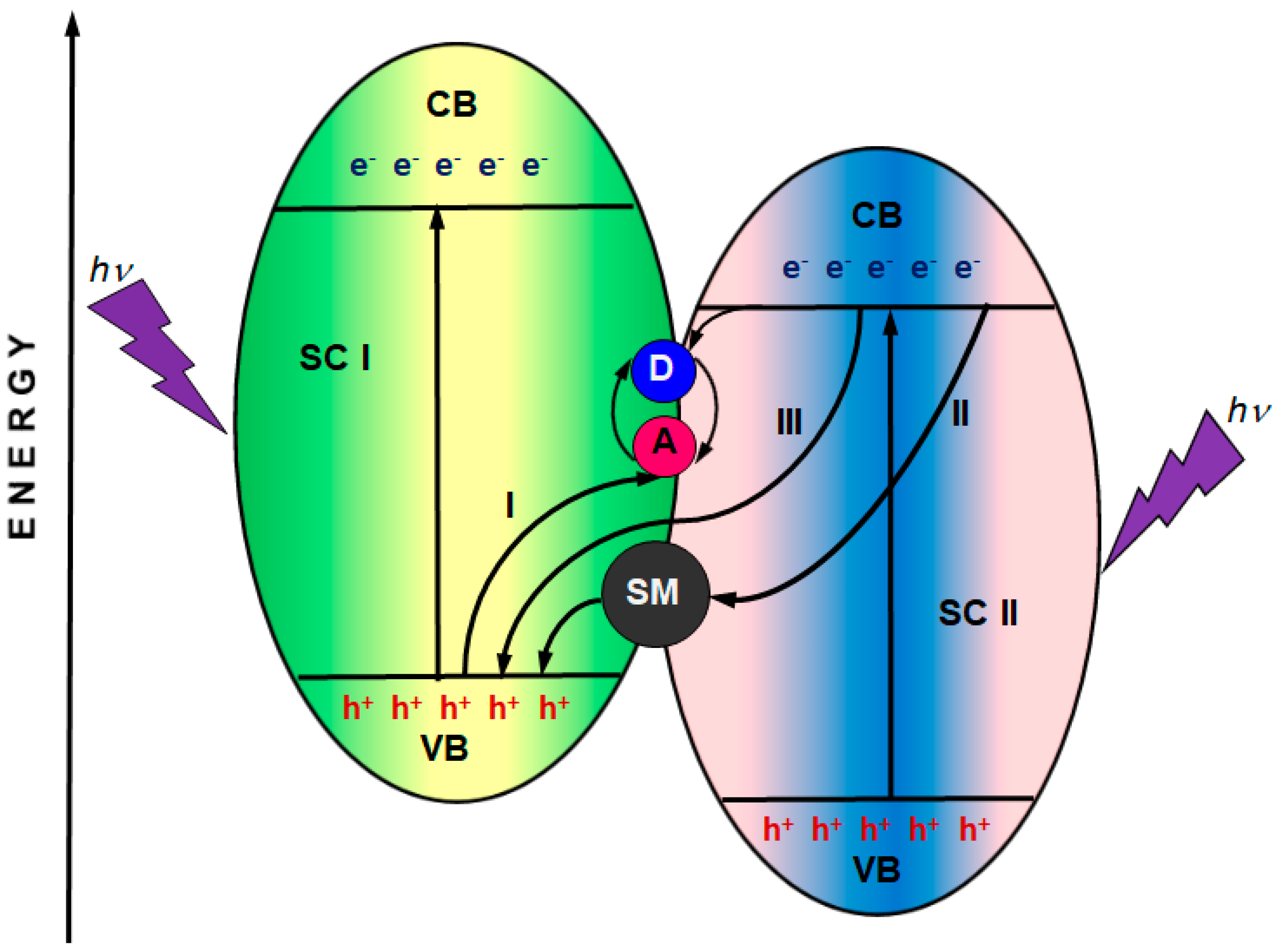
- (1)
- direct Z-scheme—mediator-free;
- (2)
- Z-scheme with a solid mediator;
- (3)
- Z-scheme with a redox pair mediator.
3.4. CeO2 as a Photoelectrocatalyst Applied in Pollutant Degradation
- (1)
- The decolorization degree determined by UV/VIS spectrophotometry:where A0 and At represent the initial and final absorbance determined in a treated solution respectively;
- (2)
- Pollutant removal:where C0 and Ct represent the initial and final concentration of a pollutant, respectively;
- (3)
- TOC and COD removal:where TOC0 and TOCt represent the initial and final values of total organic carbon, respectively, and COD0 and CODt represent the initial and final values of the chemical oxygen demand, respectively;
- (4)
- The electrical energy consumption per mass, which constitutes the main part of the operating costs:where P is the rated power (kW) of the system; V is the volume of treated wastewater (L); t is the treatment time (h); and C0 and Ct represent the initial and final mass concentrations of a pollutant in mg/L, respectively. The decolorization degree is a parameter applied in the case of colored pollutant solutions, especially dye solution. Sometimes, absorbance values are used in the determination of the pollutant concentration. TOC and COD parameters are applied in the assessment of the mineralization of organic pollutant solution, which means pollutant conversion to CO2. The electrical energy consumption constitutes the main part of the operating costs.
4. Conclusions and Future Perspectives
- (1)
- The development of CeO2 composites which are highly efficient, stable, and visible light- or sunlight-active, and are characterized by a proper band gap structure and energy for redox reactions, a high photostability during long-term utilization, and scalability, making their commercial implementation possible;
- (2)
- The development of simple and low-cost procedures for CeO2-based photocatalyst manufacturing, with special attention given to morphology control, an increase in the active surface area, and CeO2 immobilization on a substrate in order to remove it from wastewater easily and ensure electrical conductivity in the case of photoelectrodes;
- (3)
- CeO2 application in combination with the photocatalytic or electrocatalytic treatment of wastewater with simultaneous electricity and hydrogen generation.
Funding
Conflicts of Interest
References
- Chen, X.; Chen, R.; Zhu, X.; Liao, Q.; Zhang, Y.; Ye, D.; Zhang, B.; Yu, Y.; Li, J. A solar responsive cubic nanosized CuS/Cu2O/Cu photocathode with enhanced photoelectrochemical activity. J. Catal. 2019, 372, 182–192. [Google Scholar] [CrossRef]
- Nadarajan, R.; Bakar, W.A.W.A.; Ali, R.; Ismail, R. Photocatalytic degradation of 1,2-dichlorobenzene using immobilized TiO2/SnO2/WO3 photocatalyst under visible light: Application of response surface methodology. Arab. J. Chem. 2018, 11, 34–47. [Google Scholar] [CrossRef] [Green Version]
- Trandafilović, L.V.; Jovanović, D.J.; Zhang, X.; Ptasińska, S.; Dramićanin, M.D. Enhanced photocatalytic degradation of methylene blue and methyl orange by ZnO: Eu nanoparticles. Appl. Catal. B Environ. 2017, 203, 740–752. [Google Scholar] [CrossRef] [Green Version]
- Intarasuwan, K.; Amornpitoksuk, P.; Suwanboon, S.; Graidist, P. Photocatalytic dye degradation by ZnO nanoparticles prepared from X2C2O4 (X = H, Na and NH4) and the cytotoxicity of the treated dye solutions. Sep. Purif. Technol. 2017, 177, 304–312. [Google Scholar] [CrossRef]
- Zhang, A.-Y.; Wang, W.-K.; Pei, D.-N.; Yu, H.-Q. Degradation of refractory pollutants under solar light irradiation by a robust and self-protected ZnO/CdS/TiO2 hybrid photocatalyst. Water. Res. 2016, 92, 78–86. [Google Scholar] [CrossRef] [PubMed] [Green Version]
- Liu, X.; Jin, A.L.; Jia, Y.S.; Xia, T.L.; Deng, C.X.; Zhu, M.H.; Chen, C.F.; Chen, X.S. Synergy of adsorption and visible-light photocatalytic degradation of methylene blue by a bifunctional Z-scheme heterojunction of WO3/g-C3N4. Appl. Surf. Sci. 2017, 405, 359–371. [Google Scholar] [CrossRef]
- Munoz-Batista, M.J.; Fernandez-Garcia, M.; Kubacka, A. Promotion of CeO2-TiO2 photoactivity by g-C3N4: Ultraviolet and visible light elimination of toluene. Appl. Catal. B Environ. 2015, 164, 261–270. [Google Scholar] [CrossRef]
- Munoz-Batista, M.J.; Nasalevich, M.A.; Savenije, T.J.; Kapteijn, F.; Gascon, J.; Kubacka, A.; Fernandez-Garcia, M. Enhancing promoting effects in g-C3N4-Mnn+/CeO2-TiO2 ternary composites: Photo-handling of charge carriers. Appl. Catal. B Environ. 2015, 176–177, 687–698. [Google Scholar] [CrossRef]
- Yu, Y.; Zhong, Q.; Cai, W.; Ding, J. Promotional effect of N-doped CeO2 supported CoOx catalysts with enhanced catalytic activity on NO oxidation. J. Mol. Catal. A Chem. 2015, 398, 344–352. [Google Scholar] [CrossRef]
- Xiao, F.-X.; Hung, S.-F.; Miao, J.; Wang, H.-Y.; Yang, H.; Liu, B. Metal-cluster-decorated TiO2 nanotube arrays: A composite heterostructure toward versatile photocatalytic and photoelectrochemical applications. Small 2015, 11, 554–567. [Google Scholar] [CrossRef]
- Fernandez-Domene, R.M.; Rosello-Marquez, G.; Sanchez-Tovae, R.; Lucas-Granados, B. Photoelectrochemical removal of chlorfenvinphos by using WO3 nanorods: Influence of annealing temperature and operation pH. Sep. Purif. Technol. 2019, 212, 458–464. [Google Scholar] [CrossRef]
- Huda, A.; Suman, P.H.; Torquato, L.D.M.; Silva, B.F.; Handoko, C.T.; Gulo, F. Visible light-driven photoelectrocatalytic degradation of acid yellow 17 using Sn3O4 flower-like thin films supported on Ti substrate (Sn3O4/TiO2/Ti). J. Photochem. Photobiol. A 2019, 376, 196–205. [Google Scholar] [CrossRef]
- Wang, X.; Wu, Q.; Ma, H.; Ma, C.; Yu, Z.; Fu, Y.; Dong, X. Fabrication of PbO2 tipped Co3O4 nanowires for efficient photoelectrochemical decolorization of dye (reactive brilliant blue KN-R) wastewater. Sol. Energy Mater. Sol. Cells 2019, 191, 381–388. [Google Scholar] [CrossRef]
- Goulart, L.A.; Alves, S.A.; Mascaro, L.H. Photoelectrochemical degradation of bisphenol A using Cu doped WO3 electrodes. J. Electroanal. Chem. 2019, 39, 123–133. [Google Scholar] [CrossRef]
- Fernandez-Domene, R.M.; Sanchez-Tovar, R.; Lucas-Granados, B.; Munoz-Portero, M.J. Elimination of pesticide atrazine by photoelectrocatalysis using a photoanode based on WO3 nanosheets. Chem. Eng. J. 2018, 350, 1114–1124. [Google Scholar] [CrossRef]
- Chang, K.-L.; Sun, Q.; Peng, Y.-P.; Lai, S.-W.; Sung, M.; Huang, C.-Y.; Kuo, H.-W.; Sun, J.; Lin, Y.-C. Cu2O loaded titanate nanotube arrays for simultaneously photoelectrochemical ibuprofen oxidation and hydrogen generation. Chemosphere 2016, 150, 605–614. [Google Scholar] [CrossRef]
- Kasinathan, K.; Kennedy, J.; Elayaperumal, M.; Henini, M.; Malik, M. Photodegradation of organic pollutants RhB dye using UV simulated sunlight on ceria based TiO2 nanomaterials for antibacterial applications. Sci. Rep. 2016, 6, 38064. [Google Scholar] [CrossRef] [Green Version]
- Yan, H.; Wang, X.; Yao, M.; Yao, X. Band structure design of semiconductors for enhanced photocatalytic activity: The case of TiO2. Prog. Nat. Sci. 2013, 23, 402–407. [Google Scholar] [CrossRef]
- Nakata, K.; Fujishima, A. TiO2 Photocatalysis: Design and applications. J. Photochem. Photobiol. C 2012, 13, 169–189. [Google Scholar] [CrossRef]
- Kang, X.; Liu, S.; Dai, Z.; He, Y.; Song, X.; Tan, Z. Titanium dioxide: From engineering to applications. Catalysts 2019, 9, 191. [Google Scholar] [CrossRef] [Green Version]
- Shen, L.; Xing, Z.; Zou, J.; Li, Z.; Wu, X.; Zhang, Y.; Zhu, Q.; Yang, S.; Zhou, W. Black TiO2 nanobelts/g-C3N4 nanosheets laminated heterojunctions with efficient visible-light-driven photocatalytic performance. Sci. Rep. 2017, 7, 41978. [Google Scholar] [CrossRef] [PubMed]
- Sharma, D.; Mehta, B.R. Nanostructured TiO2 thin films sensitized by CeO2 as an inexpensive photoanode for enhanced photoactivity of water oxidation. J. Alloys Compd. 2018, 749, 329–335. [Google Scholar] [CrossRef]
- Sharma, D.; Sastsangi, V.R.; Shrivastav, R.; Waghmare, U.V.; Dass, S. Understanding the photoelectrochemical properties of nanostructured CeO2/CuO2 heterojunction photoanode for efficient photoelectrochemical water splitting. Int. J. Hydrog. Energy 2016, 41, 18339–18350. [Google Scholar] [CrossRef]
- Yin, D.; Zhao, F.; Zhang, L.; Zhang, X.; Liu, Y.; Zhang, T.; Wu, C.; Chen, D.; Chen, Z. Greatly enhanced photocatalytic activity of semiconductor CeO2 by integrating with upconversion nanocrystals and graphene. RSC Adv. 2016, 6, 103795–103802. [Google Scholar] [CrossRef]
- Zhang, C.; Zhang, X.; Wang, Y.; Xie, S.; Liu, Y.; Lu, X.; Tong, Y. Facile electrochemical synthesis of CeO2 hierarchical nanorods and nanowires with excellent photocatalytic activities. New J. Chem. 2014, 38, 2581–2586. [Google Scholar] [CrossRef]
- Channei, D.; Inceesungvorn, B.; Wetchakun, N.; Ukritnukun, S.; Nattestad, A.; Chen, J.; Phanichphant, S. Photocatalytic degradation of methyl orange by CeO2 and Fe-doped CeO2 films under visible light irradiation. Sci. Rep. 2014, 4, 5757. [Google Scholar] [CrossRef]
- Saranya, J.; Ranjith, K.S.; Saravanan, P.; Mangalaraj, D.; Kumar, R.T.R. Cobalt-doped cerium oxide nanoparticles: Enhanced photocatalytic activity under UV and visible light irradiation. Mater. Sci. Semicond. Process. 2014, 26, 218–224. [Google Scholar] [CrossRef]
- Li, R.; Li, C.; Yin, S.; Fu, C.; Satom, T. Synthesis of C-N Co-doped nano-CeO2 and dye degradation under compact fluorescent lamp irradiation. J. Nanosci. Nanotechnol. 2012, 12, 2797–2801. [Google Scholar] [CrossRef]
- Mittal, M.; Gupta, A.; Pandey, O.P. Role of oxygen vacancies in Ag/Au doped CeO2 nanoparticles for fast photocatalysis. Sol. Energy 2018, 165, 206–216. [Google Scholar] [CrossRef]
- Xiu, Z.; Xing, Z.; Li, Z.; Wu, X.; Yan, X.; Hu, M.; Cao, Y.; Yang, S.; Zhou, W. Ti3+-TiO2/Ce3+-CeO2 nanosheet heterojunctions as efficient visible-light-driven photocatalysts. Mater. Res. Bull. 2018, 100, 191–197. [Google Scholar] [CrossRef]
- Qu, X.; Xie, D.; Gao, L.; Du, F. Synthesis and photocatalytic activity of TiO2/CeO2 core-shell nanotubes. Mater. Sci. Semicond. Process. 2014, 26, 657–662. [Google Scholar] [CrossRef]
- Issarapanacheewin, S.; Wetchakun, K.; Phanichphant, S.; Kangwansupamokon, W.; Wetchakun, N. A novel CeO2/Bi2WO6 composite with highly enhanced photocatalytic activity. Mater. Lett. 2015, 156, 28–31. [Google Scholar] [CrossRef]
- Huang, K.; Li, Y.H.; Liang, C.; Xu, X.; Zhou, Y.F.; Fan, D.Y.; Yang, H.J.; Lang, P.L.; Zhang, R.; Wang, Y.G.; et al. One-step synthesis of reduced graphene oxide-CeO2 nanocubes composites with enhanced catalytic activity. Mater. Lett. 2014, 124, 223–226. [Google Scholar] [CrossRef]
- Aboutaleb, W.A.; El-Salamony, R.A. Effect of Fe2O3-CeO2 nanocomposite synthesis method on the Congo red dye photodegradation under visible light irradiation. Mater. Chem. Phys. 2019, 236, 121724. [Google Scholar] [CrossRef]
- Wang, B.; Zhu, B.; Yun, S.; Zhang, W.; Xia, C.; Afzal, M.; Cai, Y.; Liu, Y.; Wang, Y.; Wang, H. Fast ionic conduction in semiconductor CeO2-δ electrolyte fuel cells. NPG Asia Mater. 2019, 11, 51. [Google Scholar] [CrossRef] [Green Version]
- Wang, W.; Zhu, Q.; Dai, Q.; Wang, X. Fe doped CeO2 nanosheets for catalytic oxidation of 1,2-dichloroethane: Effect of preparation method. Chem. Eng. J. 2017, 307, 1037–1046. [Google Scholar] [CrossRef]
- Zhang, N.; Zhang, G.; Chong, S.; Zhao, H.; Huang, T.; Zhu, J. Ultrasonic impregnation of MnO2/CeO2 and its application in catalytic sono-degradation of methyl orange. J. Environ. Manag. 2018, 205, 134–141. [Google Scholar] [CrossRef]
- Toro, R.G.; Malandrino, G.; Fragala, I.L. Relationship between the nanostructures and the optical properties of CeO2 thin films. J. Phys. Chem. B 2004, 108, 16357–16364. [Google Scholar] [CrossRef]
- Avellaneda, C.O.; Berton, M.A.C.; Bulhões, L.O.S. Optical and electrochemical properties of CeO2 thin film prepared by an alkoxide route. Sol. Energy Mater. Sol. Cells 2008, 92, 240–244. [Google Scholar] [CrossRef]
- Wongkaew, A. Effect of cerium oxide and zirconium oxide to activity of catalysts. Chiang Mai J. Sci. 2008, 35, 156–162. [Google Scholar]
- Chen, H.-I.; Chang, H.-Y. Synthesis and characterization of nanocrystalline cerium oxide powders by two-stage non-isothermal precipitation. Solid State Commun. 2005, 133, 593–598. [Google Scholar] [CrossRef]
- Munoz-Batista, M.J.; Gomez-Cerezo, M.N.; Kubacka, A.; Tudela, D.; Fernandez-Garcia, M. Role of interface contact in CeO2-TiO2 photocatalytic composite materials. ACS Catal. 2014, 4, 63–72. [Google Scholar] [CrossRef]
- Lei, W.; Zhang, T.; Gu, L.; Liu, P.; Rodriquez, J.A.; Liu, G.; Liu, M. Surface-structure sensitivity of CeO2 nanocrystals in photocatalysis and enhancing the reactivity with nanogold. ACS Catal. 2015, 5, 4385–4393. [Google Scholar] [CrossRef]
- Ramezanzadeh, B.; Bahlakeh, G.; Ramezanzadeh, M. Polyaniline-cerium oxide (PAni-CeO2) coated graphene oxide for enhancement of epoxy coating corrosion protection performance on mild steel. Corros. Sci. 2018, 137, 111–126. [Google Scholar] [CrossRef]
- Zhang, W.; Wang, H.; Lv, C.; Chen, X.; Zhao, Z.; Qu, Y.; Zhu, Y. Effects of CeO2 geometry on corrosion resistance of epoxy coatings. Surf. Eng. 2020, 36, 175–183. [Google Scholar] [CrossRef]
- Younis, A.; Chu, D.; Li, S. Cerium oxide nanostructures and their applications. Chapter 3. In Functionalized Nanomaterials; Farukh, M.A., Ed.; IntechOpen: London, UK, 2016; pp. 53–68. [Google Scholar]
- Melchionna, M.; Fornasiero, P. The role of ceria-based nanostructured materials in energy applications. Mater. Today 2014, 17, 349–357. [Google Scholar] [CrossRef]
- He, Q. Experimental study on polishing performance of CeO2 and nano-SiO2 mixed abrasive. Appl. Nanosci. 2018, 8, 163–171. [Google Scholar] [CrossRef] [Green Version]
- Porqueras, I.; Person, C.; Corbella, C.; Vives, M.; Pinyol, A.; Bertran, E. Characteristics of e-beam deposited electrochromic CeO2 thin films. Solid State Ion. 2003, 165, 131–137. [Google Scholar] [CrossRef]
- Parwaiz, S.; Khan, M.M.; Pradhan, D. CeO2-based nanocomposites: An advanced alternative to TiO2 and ZnO2 in sunscreens. Mater. Express 2019, 9, 185–202. [Google Scholar] [CrossRef]
- Li, Y.; Hou, X.; Yang, C.; Pang, Y.; Li, X.; Jiang, G.; Liu, Y. Photoprotection of cerium oxide nanoparticles against UVA radiation-induced senescence of human skin fibroblasts due to their antioxidant properties. Sci. Rep. 2019, 9, 2595. [Google Scholar] [CrossRef] [Green Version]
- Pislaru-Danescu, L.; Telipan, G.; Ion, I.; Marinescu, V. Prototyping a gas sensors using CeO2 as a matrix or dopant in oxide semiconductor systems. Introductory Chapter; In Cerium Oxide—Applications and Attributes; Khan, S.B., Akhtar, K., Eds.; IntechOpen: London, UK, 2019; pp. 1–34. [Google Scholar]
- Hu, J.; Sun, Y.; Xue, Y.; Zhang, M.; Li, P.; Lian, K.; Zhuiykov, S.; Zhang, W.; Chen, Y. Highly sensitive and ultra-fast gas sensor based on CeO2-loaded In2O3 hollow spheres for ppb-level hydrogen detection. Sens. Actuators B Chem. 2018, 257, 124–135. [Google Scholar] [CrossRef]
- Li, C.; Lu, Z. Effect of CeO2 and CuO sintering additives on the properties of KNN-based piezoelectric ceramics. Mater. Technol. 2018, 33, 474–478. [Google Scholar] [CrossRef]
- Souza, J.V.C.; de Macedo Silva, O.M.; do Carmo Andrade Nono, M.; Machado, J.P.B.; Pimenta, M.; Ribeiro, M.V. S3N4 ceramics cutting tool sintered with CeO2 and Al2O3 additives with AlCrN coating. Mater. Res. 2011, 14, 514–518. [Google Scholar] [CrossRef] [Green Version]
- Gong, Q.; Gao, T.; Huang, H.; Wang, R.; Cao, P.; Zhou, G. Double-shelled CeO2@C hollow nanospheres as enhanced anode materials for lithium-ion batteries. Inorg. Chem. Front. 2018, 5, 3197–3204. [Google Scholar] [CrossRef]
- Di Monte, R.; Kaspar, J. On the role of oxygen storage in three-way catalysis. Top. Catal. 2004, 28, 47–57. [Google Scholar] [CrossRef]
- Machida, M.; Fujiwara, A.; Yoshida, H.; Ohyama, J.; Asakura, H.; Hosokawa, S.; Tanaka, T.; Haneda, M.; Tomita, A.; Miki, T.; et al. Deactivation mechanism of Pd/CeO2-ZrO2 three-way Catalysts analysed by chassis-dynamometer tests and in situ diffuse reflectance spectroscopy. ACS Catal. 2019, 9, 6415–6424. [Google Scholar] [CrossRef]
- Jiang, L.; Wei, M.; Xu, X.; Lin, Y.; Lu, Z.; Song, J.; Duan, X. SOx oxidation and adsorption by CeO2/MgO: Synergistic effect between CeO2 and MgO in the fluid catalytic cracking process. Ind. Eng. Chem. Res. 2011, 50, 4398–4404. [Google Scholar] [CrossRef]
- Ramamoorthy, R.; Dutta, P.K.; Akbar, S.A. Oxygen sensors: Materials, methods, designs and applications. J. Mater. Sci. 2003, 38, 4271–4282. [Google Scholar] [CrossRef]
- Wu, T.; Vegge, T.; Hansen, H.A. Improved electrocatalytic water splitting reaction on CeO2(111) by strain engineering: A DFT+U study. ACS Catal. 2019, 9, 4853–4861. [Google Scholar] [CrossRef]
- Umale, S.V.; Tambat, S.N.; Sontakke, S.M. Combustion synthesized CeO2 as an anodic material in dye sensitized solar cells. Mater. Res. Bull. 2017, 94, 483–488. [Google Scholar] [CrossRef]
- Chiu, F.-C.; Lai, C.-M. Optical and electrical characterizations cerium oxide thin films. J. Phys. D Appl. Phys. 2010, 43, 075104. [Google Scholar] [CrossRef]
- Skorodumova, N.V.; Ahuja, R.; Simak, S.I.; Abrikosov, I.A.; Johansson, B.; Lundqvist, B.I. Electronic, bonding, and optical properties of CeO2 and Ce2O3 from first principles. Phys. Rev. B 2001, 64, 115108. [Google Scholar] [CrossRef]
- Schwarz, K. Materials design of solid electrolytes. Proc. Natl. Acad. Sci. USA 2006, 103, 3497. [Google Scholar] [CrossRef] [PubMed] [Green Version]
- Zhang, D.; Du, X.; Shi, L.; Gao, R. Shape-controlled synthesis and catalytic application of ceria nanomaterials. Dalton Trans. 2012, 41, 14455–14475. [Google Scholar] [CrossRef]
- Sun, C.; Li, H.; Chen, L. Nanostructured ceria-based materials: Synthesis, properties, and applications. Energy Environ. Sci. 2012, 5, 8475–8505. [Google Scholar] [CrossRef]
- Zhang, J.; Kumagai, H.; Yamamura, K.; Ohara, S.; Takami, S.; Morikawa, A.; Shinjoh, H.; Kaneko, K.; Adschiri, T.; Suda, A. Extra-low-temperature oxygen storage capacity of CeO2 nanocrystals with cubic facets. Nano Lett. 2011, 11, 361–364. [Google Scholar] [CrossRef]
- Charbgoo, F.; Ramezani, M.; Darroudi, M. Bios-sensing applications of cerium oxide nanoparticles: Advantages and disadvantages. Biosens. Bioelectron. 2017, 96, 33–43. [Google Scholar] [CrossRef]
- Charbgoo, F.; Ahmad, M.B.; Darroudi, M. Cerium oxide nanoparticles: Green synthesis and biological applications. Int. J. Nanomed. 2017, 12, 1401–1413. [Google Scholar] [CrossRef] [Green Version]
- Campbell, C.T.; Peden, C.H.F. Oxygen vacancies and catalysis on ceria surfaces. Science 2005, 309, 713–714. [Google Scholar] [CrossRef]
- Gogoi, A.; Navgire, M.; Sarma, K.C.; Gogoi, P. Fe3O3-CeO2 metal oxide nanocomposite as a Fenton-like heterogeneous catalyst for degradation of catechol. Chem. Eng. J. 2017, 311, 153–162. [Google Scholar] [CrossRef]
- Wu, Z.; Li, M.; Overbury, S.H. On the structure dependence of CO oxidation over CeO2 nanocrystals with well-defined surface planes. J. Catal. 2012, 285, 61–73. [Google Scholar] [CrossRef]
- Sayle, T.X.T.; Cantoni, M.; Bhatta, U.M.; Parker, S.C.; Hall, S.R.; Möbus, G.; Molinari, M.; Reid, D.; Seal, S.; Sayle, D.C. Strain and architecture-tuned reactivity in ceria nanostructures; Enhanced Catalytic oxidation of CO to CO2. Chem. Mater. 2012, 24, 1811–1821. [Google Scholar] [CrossRef]
- Liu, L.; Cao, Y.; Sun, W.; Yao, Z.; Liu, B.; Gao, F.; Dong, L. Morphology and nanosize effects of ceria from different precursors on the activity for NO reduction. Catal. Today 2011, 175, 48–54. [Google Scholar] [CrossRef]
- Fernandez-Garcia, S.; Jiang, L.; Tinoco, M.; Hungria, A.B.; Han, J.; Blanco, G.; Calvino, J.J.; Chen, X. Enhanced hydroxyl radical scavenging activity by doping lanthanum in ceria nanocubes. J. Phys. Chem. C 2016, 120, 1891–1901. [Google Scholar] [CrossRef]
- Doornkamp, C.; Ponec, V. The universal character of the Mars and Van Krevelen mechanism. J. Mol. Catal. A Chem. 2000, 162, 19–32. [Google Scholar] [CrossRef]
- Mora-Briseno, P.; Jimenez-Garcia, G.; Castillo-Araiza, C.O.; Gonzales-Rodriguez, H.; Huirache-Acuna, R.; Maya-Yescas, R. Mars van Krevelen Mechanism for the selective partial oxidation of ethane. Int. J. Chem. React. Eng. 2018, 7, 20180085. [Google Scholar] [CrossRef]
- Li, Z.; Zhang, J.; Lv, J.; Lu, L.; Liang, C.; Dai, K. Sustainable synthesis of CeO2/CdS-diethylenetriamine composites for enhanced photocatalytic hydrogen evolution under visible light. J. Alloys Compd. 2018, 758, 162–170. [Google Scholar] [CrossRef]
- Wang, J.; Liu, P.; Fu, X.; Li, Z.; Han, W.; Wang, X. Relationship between oxygen defects and the photocatalytic property of ZnO nanocrystals in Nafion membranes. Langmuir 2009, 25, 1218–1223. [Google Scholar] [CrossRef]
- Tachikawa, T.; Yamashita, S.; Majima, T. Evidence for crystal-face-dependent TiO2 photocatalysis from single-molecule imaging and kinetic analysis. J. Am. Chem. Soc. 2011, 133, 7197–7204. [Google Scholar] [CrossRef]
- Liyanage, A.D.; Perera, S.D.; Tan, K.; Chabal, Y.; Balkus, K.J. Synthesis, characterization, and photocatalytic activity of Y-doped CeO2 nanorods. ACS Catal. 2014, 4, 577–584. [Google Scholar] [CrossRef]
- Chen, H.; Zhang, C.; Pang, Y.; Shen, Q.; Yu, Y.; Su, Y.; Wang, J.; Zhang, F.; Yang, H. Oxygen vacancy regulation in Nb-doped Bi2WO6 for enhanced visible light photocatalytic activity. RSC Adv. 2019, 9, 22559–22566. [Google Scholar] [CrossRef] [Green Version]
- Pu, Z.-Y.; Liu, X.-S.; Jia, A.-P.; Xie, Y.-L.; Lu, J.-Q.; Luo, M.-F. Enhanced activity of CO oxidation over Pr- and Cu-doped CeO2 catalysts: Effect of oxygen vacancies. J. Phys. Chem. C 2008, 12, 15045–15051. [Google Scholar] [CrossRef]
- Heydari, H.; Elahifard, M.; Behjatmanesh-Ardakani, R. Role of oxygen vacancy in the adsorption and dissociation of the water molecule on the surfaces of pure and Ni-doped rutile (110): A periodic full-potential DFT study. Surf. Sci. 2019, 679, 218–224. [Google Scholar] [CrossRef]
- Varilla, L.A.A.; Seriani, N.; Montoya, J.A. Molecular adsorption and dissociation of CO2 on TiO2 anatase (001) activated by oxygen vacancies. J. Mol. Model. 2019, 25, 231. [Google Scholar] [CrossRef]
- Kumar, S.; Kumar, A. Enhanced photocatalytic activity of rGO-CeO2 nanocomposites driven by sunlight. Mater. Sci. Eng. B 2017, 223, 98–108. [Google Scholar] [CrossRef]
- Özer, N. Optical properties and electrochromic characterization of sol-gel deposited ceria films. Sol. Energy Mater. Sol. Cells 2001, 68, 391–400. [Google Scholar] [CrossRef]
- Corma, A.; Atienzar, P.; Garcia, H.; Chane-Ching, J.-Y. Hierarchically mesostructured doped CeO2 with potential for solar-cell use. Nat. Mater. 2004, 3, 394–397. [Google Scholar] [CrossRef]
- Schmitt, R.; Nenning, A.; Kraynis, O.; Korobko, R.; Frenkel, A.I.; Lubomirsky, I.; Haile, S.M.; Rupp, J.L.M. A review of defect structure and chemistry in ceria and its solid solutions. Chem. Soc. Rev. 2019. [Google Scholar] [CrossRef] [Green Version]
- Castleton, C.W.M.; Kullgren, J.; Hermansson, K. Tuning LDA+U for electron localization and structure at oxygen vacancies in ceria. J. Chem. Phys. 2007, 127, 244704. [Google Scholar] [CrossRef]
- Keating, P.R.L.; Scanlon, K.D.O.; Morgan, B.J.; Galea, N.M.; Watson, G.W. Analysis of intrinsic defects in CeO2 using a Koopmans-like GGA+U approach. J. Phys. Chem. C 2012, 116, 2443–2452. [Google Scholar] [CrossRef]
- Song, Y.Q.; Zhang, W.W.; Yang, Q.H.; Liu, Y.L.; Li, Y.X.; Shah, L.R.; Zhu, H.; Xiao, J.Q. Electronic structure and magnetic properties of Co-doped CeO2: Based on first principle calculation. J. Phys. Condens. Matter 2009, 21, 125504. [Google Scholar] [CrossRef] [PubMed]
- Zacherle, T.; Schriever, A.; De Souza, R.A.; Martin, M. Ab initio analysis of the defect structure of ceria. Phys. Rev. B 2013, 87, 134104. [Google Scholar] [CrossRef]
- Nolan, M.; Grigoleit, S.; Sayle, D.C.; Parker, S.C.; Watson, G.W. Density functional theory studies of the structure and electronic structure of pure and defective low index surfaces of ceria. Surf. Sci. 2005, 576, 217–229. [Google Scholar] [CrossRef]
- Younis, A.; Chu, D.; Kaneti, Y.V.; Li, S. Tuning the surface oxygen concentration of {111} surrounded ceria nanocrystals for enhanced photocatalytic activities. Nanoscale 2016, 8, 378–387. [Google Scholar] [CrossRef] [PubMed]
- Raudonyte-Svirbutaviciene, E.; Neagu, A.; Vickackaite, V.; Jasulaitiene, V.; Zarkov, A.; Tai, C.-W.; Katelnikovas, A. Two-step photochemical inorganic approach to the synthesis of Ag-CeO2 nanoheterostructures and their photocatalytic activity on tributyltin degradation. J. Photochem. Photobiol. A 2018, 351, 29–41. [Google Scholar] [CrossRef]
- Hao, Y.; Li, L.; Zhang, J.; Luo, H.; Zhang, X.; Chen, E. Multilayer and open structure of dendritic crosslinked CeO2-ZrO2 composite: Enhanced photocatalytic degradation and water splitting performance. Int. J. Hydrog. Energy 2017, 42, 5916–5929. [Google Scholar] [CrossRef]
- Li, H.; Cui, Y.; Hong, W. High photocatalytic performance of BiOI/Bi2WO3 toward toluene and Reactive Brilliant Red. Appl. Surf. Sci. 2013, 264, 581–588. [Google Scholar] [CrossRef]
- Issarapanacheewin, S.; Wetchakun, K.; Phanichphant, S.; Kangwansupamonkon, W.; Wetchakun, N. Photodegradation of organic dyes by CeO2/Bi2WO6 nanocomposite and its physicochemical properties investigation. Ceram. Int. 2016, 42, 16007–16016. [Google Scholar] [CrossRef]
- Berger, T.; Monllor-Satoca, D.; Jankulovska, M.; Lana-Villarreal, T.; Gomez, R. The electrochemistry of nanostructured titanium dioxide electrodes. ChemPhysChem 2012, 13, 2824–2875. [Google Scholar] [CrossRef]
- Kusmierek, E. Semiconductor electrode materials applied in photoelectrocatalytic wastewater treatment—An overview. Catalysts 2020, 10, 439. [Google Scholar] [CrossRef] [Green Version]
- Peter, L.M. Photoelectrochemistry from basic principles to photocatalysis. Chapter 1. In Photocatalysis: Fundamentals and Perspectives; Schneider, J., Bahnemann, D., Ye, J., Puma, G.L., Dionysiou, D.D., Eds.; Royal Society of Chemistry: London, UK, 2016; pp. 3–28. [Google Scholar]
- Guijarro, N.; Prevot, M.S.; Sivula, K. Surface modification of semiconductor photoelectrodes. Phys. Chem. Chem. Phys. 2015, 17, 15655–15674. [Google Scholar] [CrossRef] [PubMed]
- Bessegato, G.G.; Guaraldo, T.T.; de Brito, J.F.; Brugnera, M.F.; Zanoni, M.V.B. Achievements and trends in photoelectrocatalysis: From environmental to energy applications. Electrocatalysis 2015, 6, 415–441. [Google Scholar] [CrossRef] [Green Version]
- Bessegato, G.G.; Guaraldo, T.T.; Zanoni, M.V.B. Enhancement of photoelectrocatalysis efficiency by using nanostructured electrodes. Chapter 10. In Modern Electrochemical Methods in Nano, Surface and Corrosion Science; Aliokhazraei, M., Ed.; IntechOpen: London, UK, 2014; pp. 271–319. [Google Scholar]
- Brugnera, M.F.; de Araujo Souza, B.C.; Zanoni, M.V.B. Advanced oxidation processes applied to actinobacterium disinfection. Chapter 15. In Antibacteria—Basics and Biotechnological Applications; Dhanasekaran, D., Ed.; IntechOpen: London, UK, 2016; pp. 353–376. [Google Scholar]
- Paramasivam, I.; Jha, H.; Liu, N.; Schmuku, P. A review of photocatalysis using self-organized TiO2 nanotubes and other ordered oxide nanostructure. Small 2012, 8, 3073–3103. [Google Scholar] [CrossRef]
- Tan, Y.; Zhang, S.; Shi, R.; Wang, W.; Liang, K. Visible light active Ce/Ce2O/CeO2/TiO2 nanotube arrays for efficient hydrogen production by photoelectrochemical water splitting. Int. J. Hydrog. Energy 2016, 41, 5437–5444. [Google Scholar] [CrossRef]
- Chaudhary, P.; Ingole, P.P. In-situ solid-state synthesis of 2D/2D interface between Ni/NiO hexagonal nanosheets supported on g-C3N4 for enhanced photo-electrochemical water splitting. Int. J. Hydrog. Energy 2020, 45, 16060–16079. [Google Scholar] [CrossRef]
- Anwer, H.; Mahmood, A.; Lee, J.; Kim, K.-H.; Park, J.-W.; Yip, A.C.K. Photocatalysts for degradation of dyes in industrial effluents: Opportunities and challenges. Nano Res. 2019, 12, 955–972. [Google Scholar] [CrossRef]
- Zangeneh, H.; Zinatizadeh, A.A.L.; Habibi, M.; Akia, M.; Isa, M.H. Photocatalytic oxidation of organic dyes and pollutants in wastewater using different modified titanium dioxides: A comparative study. J. Ind. Eng. Chem. 2015, 26, 1–36. [Google Scholar] [CrossRef]
- Kuhn, H.J.; Braslavsky, S.E.; Schmidt, R. Chemical actinometry (IUPAC Technical Report). Pure Appl. Chem. 2004, 76, 2105–2146. [Google Scholar] [CrossRef]
- Sun, L.; Bolton, J.R. Determination of the quantum yield for the photochemical generation of hydroxyl radicals in TiO2 suspension. J. Phys. Chem. 1996, 100, 4127–4134. [Google Scholar] [CrossRef]
- Ling, L.; Tugaoen, H.; Brame, J.; Sinha, S.; Li, C.; Schoepf, J.; Hristovski, K.; Kim, J.-H.; Shang, C.; Westerhoff, P. Coupling light emitting diodes with photocatalyst-coated optical fibers improves quantum yield of pollutant oxidation. Environ. Sci. Technol. 2017, 51, 13319–13326. [Google Scholar] [CrossRef]
- Anwer, H.; Park, J.-W. Near-infrared to visible photon transition by upconverting NaYF4: Yb3+, Gd3+, Tm3+ @ Bi2WO6 core@ shell composite for bisphenol A degradation in solar light. Appl. Catal. B 2019, 243, 438–447. [Google Scholar] [CrossRef]
- Goharshadi, E.K.; Samiee, S.; Nancarrow, P. Fabrication of cerium oxide nanoparticles: Characterization and optical properties. J. Colloid Interface Sci. 2011, 356, 473–480. [Google Scholar] [CrossRef] [PubMed]
- Dong, B.; Li, L.; Dong, Z.; Xu, R.; Wu, Y. Fabrication of CeO2 nanorods for enhanced solar photocatalysts. Int. J. Hydrog. Energy 2018, 43, 5275–5282. [Google Scholar] [CrossRef]
- Khan, M.E.; Khan, M.M.; Cho, M.H. Ce3+-ion, surface oxygen vacancy, and visible light-induced photocatalytic dye degradation and photocapacitive performance of CeO2-graphene nanostructures. Sci. Rep. 2017, 7, 5928. [Google Scholar] [CrossRef] [PubMed] [Green Version]
- Wang, J.; Han, A.; Jaenicke, S.; Chuah, G.-K. Advances in sorbents and photocatalytic materials for water remediation. Chapter 6. In New and Future Developments in Catalysis—Catalysis for Remediation and Environmental Concerns; Suib, S.L., Ed.; Elsevier: Amsterdam, The Netherlands, 2013; pp. 127–153. [Google Scholar]
- Capodaglio, A.G. Contaminants of emerging concern removal by high-energy oxidation-reduction processes: State of the art. Appl. Sci. 2019, 9, 4562. [Google Scholar] [CrossRef] [Green Version]
- Armstrong, D.A.; Huie, R.E.; Lymar, S.; Koppenol, W.H.; Merenyi, G.; Neta, P.; Stanbury, D.M.; Steenken, S.; Wardman, P. Standard electrode potentials involving radicals in aqueous solution: Inorganic radicals (IUPAC Technical Report). Pure Appl. Chem. 2015, 87, 1139–1150. [Google Scholar] [CrossRef]
- Zamiri, R.; Ahangar, H.A.; Kaushal, A.; Zakaria, A.; Zamiri, G.; Tobaldi, D.; Ferreira, J.M.F. Dielectrical properties of CeO2 nanoparticles at different temperatures. PLoS ONE 2015, 10, e0122989. [Google Scholar]
- Renu, G.; Rani, V.V.D.; Nair, S.V.; Subramanian, K.R.V.; Lakshmanan, V.-K. Development of cerium oxide nanoparticles and its cytotoxicity in prostate cancer cells. Adv. Sci. Lett. 2012, 5, 1–9. [Google Scholar] [CrossRef]
- Tarnuzzer, R.W.; Colon, J.; Patil, S.; Seal, S. Vacancy engineered ceria nanostructures for protection from radiation-induced cellular damage. Nano Lett. 2005, 5, 2573–2577. [Google Scholar] [CrossRef] [PubMed]
- Phuruangrat, A.; Thongtem, S.; Thongtem, T. Microwave-assisted hydrothermal synthesis and characterization of CeO2 nanowires for using as a photocatalytic material. Mater. Lett. 2017, 196, 61–63. [Google Scholar] [CrossRef]
- Ji, P.; Zhang, J.; Chen, F.; Anpo, M. Study of adsorption and degradation of acid orange 7 on the surface of CeO2 under visible light irradiation. Appl. Catal. B Environ. 2009, 85, 148–154. [Google Scholar] [CrossRef]
- Ji, P.; Tian, B.; Chen, F.; Zhang, J. CeO2 mediated photocatalytic degradation studies of C.I. acid orange 7. Environ. Technol. 2012, 33, 467–472. [Google Scholar] [CrossRef] [PubMed]
- Tambat, S.; Umale, S.; Sontakke, S. Photocatalytic degradation of Milling Yellow dye using sol-gel synthesized CeO2. Mater. Res. Bull. 2016, 76, 466–472. [Google Scholar] [CrossRef]
- Aslam, M.; Qamar, M.T.; Soomro, M.T.; Ismail, I.M.I.; Salah, N.; Almeelbi, T.; Gondal, M.A.; Hameed, A. The effect of sunlight induced surface defects on the photocatalytic activity of nanosized CeO2 for the degradation of phenol and its derivatives. Appl. Catal. B Environ. 2016, 180, 391–402. [Google Scholar] [CrossRef]
- Khan, M.M.; Ansari, S.A.; Pradhan, D.; Han, D.H.; Lee, J.; Cho, M.H. Defect-induced band gap narrowed CeO2 nanostructures for visible light activities. Ind. Eng. Chem. Res. 2014, 53, 9754–9763. [Google Scholar] [CrossRef]
- Zheng, X.; Huang, S.; Yang, D.; Zhai, H.; You, Y.; Fu, X.; Yuan, J.; Zhou, X.; Wen, J.; Liu, Y. Synthesis of X-architecture CeO2 for the photodegradation of methylene blue under UV-light irradiation. J. Alloys Compd. 2017, 705, 131–137. [Google Scholar] [CrossRef]
- Amoresi, R.A.C.; Oliveira, R.C.; Marana, N.L.; de Almeida, P.B.; Prata, P.S.; Zaghete, M.A.; Longo, E.; Sambrano, J.R.; Simoes, A.Z. CeO2 nanoparticle morphologies and their corresponding crystalline planes for the photocatalytic degradation of organic pollutants. ACS Appl. Nano Mater. 2019, 2, 6513–6526. [Google Scholar] [CrossRef]
- Channei, D.; Nakaruk, A.; Phanichphant, S. Photocatalytic degradation of dye using CeO2/SCB composite catalysts. Spectrochim. Acta A Mol. Biomol. Spectrosc. 2017, 183, 218–224. [Google Scholar] [CrossRef]
- Yang, K.; Huang, W.-Q.; Xu, L.; Luo, K.-W.; Yang, Y.-C.; Huang, G.-F. Insights into enhanced visible-light photocatalytic activity of CeO2 doped with nonmetal impurity from the first principles. Mater. Sci. Semicond. Process. 2016, 41, 200–208. [Google Scholar] [CrossRef]
- Miao, H.; Huang, G.-F.; Liu, J.-H.; Zhou, B.-X.; Pan, A.; Huang, W.-Q.; Huang, G.-F. Origin of enhanced photocatalytic activity of F-doped CeO2 nanocubes. Appl. Surf. Sci. 2016, 370, 427–432. [Google Scholar] [CrossRef]
- Wu, C. Solvothermal synthesis of N-doped CeO2 microspheres with visible light-driven photocatalytic activity. Mater. Lett. 2015, 139, 383–384. [Google Scholar] [CrossRef]
- Mao, C.; Zhao, Y.; Qiu, X.; Zhu, J.; Burda, C. Synthesis, characterization and computational study of nitrogen-doped CeO2 nanoparticles with visible-light activity. Phys. Chem. Chem. Phys. 2008, 10, 5633–5638. [Google Scholar] [CrossRef]
- Akbari-Fakhrabai, A.; Saravanan, R.; Jamshidijam, M.; Mangalaraja, R.V.; Gracia, M.A. Preparation of nanosized yttrium doped CeO2 catalyst used for photocatalytic application. J. Saudi Chem. Soc. 2015, 19, 505–510. [Google Scholar] [CrossRef] [Green Version]
- Xu, B.; Zhang, Q.; Yuan, S.; Zhang, M.; Ohno, T. Morphology control and photocatalytic characterization of yttrium-doped hedgehog-like CeO2. Appl. Catal. B Environ. 2015, 164, 120–127. [Google Scholar] [CrossRef] [Green Version]
- Murugan, R.; Kashinath, L.; Subash, R.; Sakhivel, P.; Byrappa, K.; Rajendran, S.; Ravi, G. Pure and alkaline metal ion (Mg, Ca, Sr, Ba) doped cerium oxide nanostructures for photo degradation of methylene blue. Mater. Res. Bull. 2018, 97, 319–325. [Google Scholar] [CrossRef]
- Murugadoss, G.; Ma, J.; Ning, X.; Kumar, M.R. Selective metal ions doped CeO2 nanoparticles for excellent photocatalytic activity under sun light and supercapacitor application. Inorg. Chem. Commun. 2019, 109, 107577. [Google Scholar] [CrossRef]
- Channei, D.; Inceesungvorn, B.; Wetchakun, N.; Phanichphant, S.; Nakaruk, A.; Koshy, P.; Sorrell, C.C. Photocatalytic activity under visible light of Fe-doped CeO2 nanoparticles synthesized by flame spray pyrolysis. Ceram. Int. 2013, 39, 3129–3134. [Google Scholar] [CrossRef]
- Arul, N.S.; Mangalaraj, D.; Han, J.I. Enhanced photocatalytic property of self-assembled Fe-doped CeO2 hierarchical nanostructures. Mater. Lett. 2015, 145, 189–192. [Google Scholar] [CrossRef]
- Zhao, B.; Shao, Q.; Hao, L.; Zhang, L.; Liu, Z.; Zhang, B.; Ge, S.; Guo, Z. Yeast-template synthesized Fe-doped cerium oxide hollow microspheres for visible photodegradation of acid orange 7. J. Colloid Interface Sci. 2018, 511, 39–47. [Google Scholar] [CrossRef]
- Arul, N.S.; Mangalaraj, D.; Chen, P.C.; Ponpandian, N.; Viswanathan, C. Self assembly of Co doped CeO2 microspheres from nanocubes by hydrothermal method and their photodegradation activity on AO7. Mater. Lett. 2011, 65, 3320–3322. [Google Scholar] [CrossRef]
- Singh, K.; Kumar, K.; Srivastava, S.; Chowdhury, A. Effect of rare-earth doping in CeO2 matrix: Correlations with structure, catalytic and visible light photocatalytic properties. Ceram. Int. 2017, 43, 17041–17047. [Google Scholar] [CrossRef]
- Chen, X.; Mao, S.S. Titanium dioxide materials: Synthesis, properties, modifications, and applications. Chem. Rev. 2007, 107, 2891–2959. [Google Scholar] [CrossRef]
- Jorge, A.B.; Fraxedas, J.; Cantarero, A.; Williams, A.J.; Rodgers, J.; Attfield, J.P.; Fuertes, A. Nitrogen doping ceria. Chem. Mater. 2008, 20, 1682–1684. [Google Scholar] [CrossRef]
- Yue, L.; Zhang, X.-M. Structural characterization and photocatalytic behaviours of doped CeO2 nanoparticles. J. Alloys Compd. 2009, 475, 702–705. [Google Scholar] [CrossRef]
- Vinodkumar, T.; Rao, B.G.; Reddy, B.M. Influence of isovalent and aliovalent dopants on the reactivity of cerium oxide for catalytic applications. Catal. Today 2015, 253, 57–64. [Google Scholar] [CrossRef]
- Wang, H.; Zhang, L.; Chen, Z.; Hu, J.; Li, S.; Wang, Z.; Liu, J.; Wang, X. Semiconductor heterojunction photocatalyst: Design, construction, and photocatalytic performances. Chem. Soc. Rev. 2014, 43, 5234–5244. [Google Scholar] [CrossRef]
- Peleyeju, M.G.; Arotiba, O.A. Recent trend in visible-light photoelectrocatalytic systems for degradation of organic contaminants in water/wastewater. Environ. Sci. Water Res. Technol. 2018, 4, 1389–1411. [Google Scholar] [CrossRef]
- Ge, J.; Zhang, Y.; Heo, Y.-J.; Park, S.-J. Advanced design and synthesis of composite photocatalyst for the remediation of wastewater: A review. Catalysts 2019, 9, 122. [Google Scholar] [CrossRef] [Green Version]
- Low, J.; Jaroniec, M.; Wageh, S.; Al-Ghamdi, A.A. Heterojunction photocatalysts. Adv. Mater. 2017, 29, 1601694. [Google Scholar] [CrossRef]
- Ameen, S.; Akhtar, M.S.; Seo, H.-K.; Shin, H.-S. Solution processed CeO2/TiO2 nanocomposite as potent visible light photocatalyst for the degradation of bromophenol dye. Chem. Eng. J. 2014, 247, 193–198. [Google Scholar] [CrossRef]
- Wang, N.; Pan, Y.; Lu, T.; Li, X.; Wu, S.; Wu, J. A new ribbon-ignition method for fabricating p-CuO/n-CeO2 heterojunction with enhanced photocatalytic activity. Appl. Surf. Sci. 2017, 403, 699–706. [Google Scholar] [CrossRef]
- Zhu, L.; Li, H.; Xia, P.; Liu, Z.; Xiong, D. Hierarchical ZnO decorated CeO2 nanoparticles as the direct Z-scheme heterojunctions for enhanced photocatalytic activity. ACS Appl. Mater. Interfaces 2018, 10, 39679–39687. [Google Scholar] [CrossRef] [PubMed]
- Qiao, Q.; Yang, K.; Ma, L.-L.; Huang, W.-Q.; Zhou, B.-X.; Pan, A.; Hu, W.; Fan, X.; Huang, G.-F. Facile in situ construction of mediator-free direct Z-scheme g-C3N4/CeO2 heterojunctions with highly efficient photocatalytic activity. J. Phys. D Appl. Phys. 2018, 51, 275302. [Google Scholar] [CrossRef]
- Li, H.; Tu, W.; Zhou, Y.; Zou, Z. Z-Scheme photocatalytic systems for promoting photocatalytic performance: Recent progress and future challenges. Adv. Sci. 2016, 3, 1500389. [Google Scholar] [CrossRef] [Green Version]
- Hao, C.; Li, J.; Zhang, Z.; Ji, Y.; Zhan, H.; Xiao, F.; Wang, D.; Liu, B.; Su, F. Enhancement of photocatalytic properties of TiO2 nanoparticles doped with CeO2 and supported on SiO2 for phenol degradation. Appl. Surf. Sci. 2015, 331, 17–26. [Google Scholar] [CrossRef]
- Li, G.; Zhang, D.; Yu, J.C. Thermally stable mesoporous CeO2/TiO2 visible light photocatalysts. Phys. Chem. Chem. Phys. 2009, 11, 3775–3782. [Google Scholar] [CrossRef]
- Liriano-Jorge, C.F.; Sohmen, U.; Özkan, A.; Gulyas, H.; Otterpohl, R. TiO2 photocatalyst nanoparticle separation: Flocculation in different matrices and use of powdered activated carbon as a precoat in low-cost fabric filtration. Adv. Mater. Sci. Eng. 2014, 602495. [Google Scholar]
- Szabo, T.; Veres, A.; Cho, E.; Khim, J.; Varga, N.; Dekany, I. Photocatalyst separation from aqueous dispersion using graphene oxide/TiO2 nanocomposites. Colloids Surf. A Physicochem. Eng. Asp. 2013, 433, 230–239. [Google Scholar] [CrossRef]
- Moongraksathum, B.; Chen, Y.-W. CeO2-TiO2 mixed oxide thin films with enhanced photocatalytic degradation of organic pollutants. J. Sol-Gel Sci. Technol. 2017, 82, 772–782. [Google Scholar] [CrossRef]
- Eskandarloo, H.; Badiei, A.; Behnajady, M.A. TiO2/CeO2 hybrid photocatalyst with enhanced photocatalytic activity: Optimization of synthesis variables. Ind. Eng. Chem. Res. 2014, 53, 7847–7855. [Google Scholar] [CrossRef]
- Tuyen, L.T.T.; Quang, D.A.; Toan, T.T.T.; Tung, T.Q.; Hoa, T.T.; Mau, T.X.; Khieu, D.Q. Synthesis of CeO2/TiO2 nanotubes and heterogeneous photocatalytic degradation of methylene blue. J. Environ. Chem. Eng. 2018, 6, 5999–6011. [Google Scholar] [CrossRef]
- Liu, H.; Wang, M.; Wang, Y.; Liang, Y.; Cao, W.; Su, Y. Ionic liquid-templated synthesis of mesoporous CeO2-TiO2 nanoparticles and their enhanced photocatalytic activities under UV or visible light. J. Photochem. Photobiol. A 2011, 223, 157–164. [Google Scholar] [CrossRef]
- Lu, X.; Li, X.; Qian, J.; Miao, N.; Yao, C.; Chen, Z. Synthesis and characterization of CeO2/TiO2 nanotube arrays and enhanced photocatalytic oxidative desulfurization performance. J. Alloys Compd. 2016, 661, 363–371. [Google Scholar] [CrossRef]
- Chen, F.; Ho, P.; Ran, R.; Chen, W.; Si, Z.; Wu, X.; Weng, D.; Huang, Z.; Lee, C. Synergistic effect of CeO2 modified TiO2 photocatalyst on the enhancement of visible light photocatalytic performance. J. Alloys Compd. 2017, 714, 560–566. [Google Scholar] [CrossRef]
- Yuan, B.; Long, Y.; Wu, L.; Liang, K.; Wen, H.; Luo, S.; Huo, H.; Yang, H.; Ma, J. TiO2@h-CeO2: A composite yolk-shell microsphere with enhanced photodegradation activity. Catal. Sci. Technol. 2016, 6, 6396–6405. [Google Scholar] [CrossRef]
- Zhang, L.; Zhang, J.; Jiu, H.; Zhang, X.; Xu, M. Preparation of hollow core/shell CeO2@TiO2 with enhanced photocatalytic performance. J. Mater. Sci. 2015, 50, 5228–5237. [Google Scholar] [CrossRef]
- Liu, Y.; Li, T.; Chen, W.; Guo, Y.; Liu, L.; Guo, H. Hierarchical hollow TiO2@CeO2 nanocube heterostructures for photocatalytic detoxification of cyanide. RSC Adv. 2015, 5, 11733–11737. [Google Scholar] [CrossRef]
- Sivalingam, J.R.; Kait, C.F.; Wilfred, C.D. CeO2-TiO2 photocatalyst: Ionic liquid-mediated synthesis, characterization, and performance for diisopropanolamine visible light degradation. Bull. Chem. React. Eng. Catal. 2018, 13, 170–178. [Google Scholar] [CrossRef] [Green Version]
- Vieira, G.B.; Jose, H.J.; Peterson, M.; Baldissarelli, V.Z.; Alvarez, P.; Moreira, R.F.P.M. CeO2/TiO2 nanostructures enhanced adsorption and photocatalytic degradation of organic compounds in aqueous suspension. J. Photochem. Photobiol. A 2018, 353, 325–336. [Google Scholar] [CrossRef]
- Velasco, L.F.; Parra, J.B.; Ania, C.O. Role of activated carbon features on the photocatalytic degradation of phenol. Appl. Surf. Sci. 2010, 256, 5254–5258. [Google Scholar] [CrossRef] [Green Version]
- Wang, M.Y.; Zhu, W.; Zhang, D.E.; Li, S.A.; Ma, W.X.; Tong, Z.W.; Chen, J. CeO2 hollow nanospheres decorated reduced graphene oxide composite for efficient photocatalytic dye-degradation. Mater. Lett. 2014, 137, 229–232. [Google Scholar]
- Lam, S.-M.; Sin, J.-C.; Mohamed, A.R. A review on photocatalytic application of g-C3N4/semiconductor (CNS) nanocomposites towards the erasure of dyeing wastewater. Mater. Sci. Semicond. Process. 2016, 47, 62–84. [Google Scholar] [CrossRef]
- Xiang, Q.; Yu, J.; Jaroniec, M. Graphene-based semiconductor photocatalysts. Chem. Soc. Rev. 2011. [Google Scholar] [CrossRef] [PubMed]
- Gusain, R.; Kumar, P.; Sharma, O.P.; Jain, S.L.; Khatri, O.P. Reduced graphene oxide-CuO nanocomposites for photocatalytic conversion of CO2 into methanol under visible light irradiation. Appl. Catal. B Environ. 2016, 181, 352–362. [Google Scholar] [CrossRef]
- Chang, H.; Wu, H. Graphene-based nanocomposites: Preparation, functionalization, and energy and environmental applications. Energy Environ. Sci. 2013, 6, 3483–3507. [Google Scholar] [CrossRef]
- Albero, J.; Mateo, D.; Garcia, H. Graphene-based materials as efficient photocatalysts for water splitting. Molecules 2019, 24, 906. [Google Scholar] [CrossRef] [Green Version]
- Dreyer, D.R.; Ruoff, R.S.; Bielawski, C.W. From conception to realization: An historial account of graphene and some perspectives for its future. Angew. Chem. Int. Ed. 2010, 49, 9336–9344. [Google Scholar] [CrossRef]
- Inagaki, M.; Tsumura, T.; Kinumoto, T.; Toyoda, M. Graphitic carbon nitrides (g-C3N4) with comparative discussion to carbon materials. Carbon 2019, 141, 580–607. [Google Scholar] [CrossRef]
- Darkwah, W.K.; Oswald, K.A. Photocatalytic applications of heterostructure graphitic carbon nitride: Pollutant degradation, hydrogen gas production (water splitting), and CO2 reduction. Nanoscale Res. Lett. 2019, 14, 234. [Google Scholar] [CrossRef]
- Samsudin, M.F.R.; Bacho, N.; Sufian, S. Recent development of graphitic carbon nitride-based photocatalyst for environmental pollution remediation. Chapter 3. In Nanocatalysts; Sinha, I., Shukla, M., Eds.; IntechOpen: London, UK, 2018; pp. 1–15. [Google Scholar]
- Ji, Z.; Shen, X.; Li, M.; Zhou, H.; Zhu, G.; Chen, K. Synthesis of reduced graphene oxide/CeO2 nanocomposites and their photocatalytic properties. Nanotechnology 2013, 24, 115603. [Google Scholar] [CrossRef]
- Murali, A.; Sarswat, P.K.; Free, M.L. Minimizing electron-hole pair recombination through band-gap engineering in novel ZnO-CeO2-rGO ternary nanocomposite for photoelectrochemical and photocatalytic applications. Environ. Sci. Pollut. Res. 2010, 27, 25042–25056. [Google Scholar] [CrossRef] [PubMed]
- Huang, T.; Wu, J.; Zhao, Z.; Zeng, T.; Zhang, J.; Xu, A.; Zhou, X.; Qi, Y.; Ren, J.; Zhou, R.; et al. Synthesis and photocatalytic performance of CuO-CeO2/graphene oxide. Mater. Lett. 2016, 185, 503–506. [Google Scholar] [CrossRef]
- Huang, L.; Li, Y.; Xu, H.; Xu, Y.; Xia, J.; Wang, K.; Li, H.; Cheng, X. Synthesis and characterization of CeO2/g-C3N4 composites with enhanced visible-light photocatalytic activity. RSC Adv. 2013, 3, 22269–22279. [Google Scholar] [CrossRef]
- Tian, N.; Huang, H.; Liu, C.; Dong, F.; Zhang, T.; Du, X.; Yu, S.; Zhang, Y. In situ co-pyrolysis fabrication of CeO2/g-C3N4 n-n type heterojunction for synchronously promoting photo-induced oxidation and reduction properties. J. Mater. Chem. A 2015, 3, 17120–17129. [Google Scholar] [CrossRef]
- Liu, W.; Zhou, J.; Hu, Z. Nano-sized g-C3N4 thin layer @ CeO2 sphere core-shell photocatalyst combined with H2O2 to degrade doxycycline in water under visible light irradiation. Sep. Purif. Technol. 2019, 227, 115665. [Google Scholar] [CrossRef]
- Jourshabani, M.; Shariatinia, Z.; Badiei, A. Facile one-pot synthesis of cerium oxide/sulfur-doped graphitic carbon nitride (g-C3N4) as efficient nanophotocatalysts under visible light irradiation. J. Colloid Interface Sci. 2017, 507, 59–73. [Google Scholar] [CrossRef]
- Li, X.; Zhu, W.; Lu, X.; Zuo, S.; Yao, C.; Ni, C. Integrated nanostructures of CeO2/attapulgite/g-C3N4 as efficient catalyst for photocatalytic desulfurization: Mechanism, kinetics and influencing factors. Chem. Eng. J. 2017, 326, 87–98. [Google Scholar] [CrossRef]
- Vignesh, S.; Suganthi, S.; Sundar, J.K.; Raj, V. Construction of α-Fe2O3/CeO2 decorated g-C3N4 nanosheets for magnetically separable efficient photocatalytic performance under visible light exposure and bacterial disinfection. Appl. Surf. Sci. 2019, 488, 763–777. [Google Scholar] [CrossRef]
- Yuan, Y.; Huang, G.-F.; Hu, W.-Y.; Xiong, D.-N.; Zhou, B.-X.; Chang, S.; Huang, W.-Q. Construction of g-C3N4/CeO2/ZnO ternary photocatalysts with enhanced photocatalytic performance. J. Phys. Chem. Solids 2017, 106, 1–9. [Google Scholar] [CrossRef]
- Stelo, F.; Kublik, N.; Ullah, S.; Wender, H. Recent advances in Bi2MoO6 based Z-scheme heterojunctions for photocatalytic degradation of pollutants. J. Alloys Compd. 2020, 829, 154591. [Google Scholar] [CrossRef]
- You, L.; Gao, M.; Li, T.; Guo, L.; Chen, P.; Liu, M. Investigation of the kinetics and mechanism of Z-scheme Ag3PO4/WO3 p-n junction photocatalysts with enhanced removal efficiency for RhB. New. J. Chem. 2019, 43, 17104. [Google Scholar] [CrossRef]
- Issarapanacheewin, S.; Wetchakun, K.; Phanichphant, S.; Kangwansupamonkon, W.; Wetchakun, N. Efficient photocatalytic degradation of Rhodamine B by a novel CeO2/Bi2WO6 composite film. Catal. Today 2016, 278, 280–290. [Google Scholar] [CrossRef]
- Lv, Z.; Zhou, H.; Liu, H.; Liu, B.; Liang, M.; Guo, H. Controlled assemble of oxygen vacant CeO2@Bi2WO6 hollow magnetic microcapsule heterostructures for visible-light photocatalytic activity. Chem. Eng. J. 2017, 330, 1297–1305. [Google Scholar] [CrossRef]
- Liu, Y.; Zhu, G.; Gao, J.; Hojamberdiev, M.; Lu, H.; Zhu, R.; Wei, X.; Liu, P. A novel CeO2/Bi4Ti3O12 composite heterojunction structure with an enhanced photocatalytic activity for bisphenol A. J. Alloys Compd. 2016, 688, 487–496. [Google Scholar] [CrossRef]
- Dai, W.; Hu, X.; Wang, T.; Xiong, W.; Luo, X.; Zou, J. Hierarchical CeO2/Bi2MoO6 heterostructured nanocomposites for photoreduction of CO2 into hydrocarbons under visible light irradiation. Appl. Surf. Sci. 2018, 434, 481–491. [Google Scholar] [CrossRef]
- Hsieh, S.-H.; Manivel, A.; Lee, G.-J.; Wu, J.J. Synthesis of mesoporous Bi2O3/CeO2 microsphere for photocatalytic degradation of Orange II dye. Mater. Res. Bull. 2013, 48, 4174–4180. [Google Scholar] [CrossRef]
- Wen, X.-J.; Niu, C.-G.; Zhang, L.; Zeng, G.-M. Novel p-n heterojunction BiOI/CeO2 photocatalyst for wider spectrum visible-light photocatalytic degradation of refractory pollutants. Dalton Trans. 2017, 46, 4982–4993. [Google Scholar] [CrossRef]
- Gu, S.; Li, W.; Wang, F.; Wang, S.; Zhou, H.; Li, H. Synthesis of buckhorn-like BiVO4 with a shell of CeOx nanodots: Effect of heterojunction structure on the enhancement of photocatalytic activity. Appl. Catal. B Environ. 2015, 170–171, 186–194. [Google Scholar] [CrossRef]
- Wetchakun, N.; Chaiwichain, S.; Inceesungvorn, B.; Pingmuang, K.; Phanichphant, S.; Minett, A.I.; Chen, J. BiVO4/CeO2 nanocomposites with high visible-light-induced photocatalytic activity. ACS Appl. Mater. Interfaces 2012, 4, 3718–3723. [Google Scholar] [CrossRef]
- Yang, Z.-M.; Huang, G.-F.; Huang, W.-Q.; Wei, J.-M.; Yan, X.-G.; Liu, Y.-Y.; Jiao, C.; Wan, Z.; Pan, A. Novel Ag3PO4/CeO2 composite with high efficiency and stability for photocatalytic applications. J. Mater. Chem. A 2014, 2, 1750–1756. [Google Scholar] [CrossRef]
- Lin, W.; Zhang, S.; Wang, D.; Zhang, C.; Sun, D. Ultrasound-assisted synthesis of high-efficiency Ag3PO4/CeO2 heterojunction photocatalyst. Ceram. Int. 2015, 41, 8956–8963. [Google Scholar] [CrossRef]
- Xiong, W.; Dai, W.; Hu, X.; Yang, L.; Wang, T.; Qin, Y.; Luo, X.; Zou, J. Enhanced photocatalytic reduction of CO2 into alcohols on Z-scheme Ag/Ag3PO4/CeO2 driven by visible light. Mater. Lett. 2018, 232, 36–39. [Google Scholar] [CrossRef]
- Wen, X.-J.; Niu, C.-G.; Ruan, M.; Zhang, L.; Zeng, G.-M. AgI nanoparticles-decorated CeO2 microsheets photocatalyst for the degradation of organic dye and tetracycline under visible-light irradiation. J. Colloid Interface Sci. 2017, 497, 368–377. [Google Scholar] [CrossRef] [PubMed]
- Wen, X.-J.; Niu, C.-G.; Zhang, L.; Liang, C.; Zeng, G.-M. A novel Ag2O/CeO2 heterojunction photocatalysts for photocatalytic degradation of enrofloxacin: Possible degradation pathways, mineralization activity and an in depth mechanism insight. Appl. Catal. B Environ. 2018, 221, 701–704. [Google Scholar] [CrossRef]
- Wen, X.-J.; Niu, C.-G.; Guo, H.; Liang, C.; Zeng, G.-M. Photocatalytic degradation of levofloxacin by ternary Ag2CO3/CeO2/AgBr photocatalyst under visible-light irradiation: Degradation pathways, mineralization ability, and an accelerated interfacial charge transfer process study. J. Catal. 2018, 358, 211–223. [Google Scholar] [CrossRef]
- Madkour, M.; Allam, O.G.; Nazeer, A.A.; Amin, M.O.; Al-Hetlani, E. CeO2-based nanoheterostructures with p-n and n-n heterojunction arrangements for enhancing the solar-driven photodegradation of rhodamine 6G dye. J. Mater. Sci. Mater. Electron. 2019, 30, 10857–10866. [Google Scholar] [CrossRef]
- Saravanan, R.; Joicy, S.; Gupta, V.K.; Narayanan, V.; Stephen, A. Visible light induced degradation of methylene blue using CeO2/V2O5 and CeO2/CuO catalysts. Mater. Sci. Eng. C 2013, 33, 4725–4731. [Google Scholar] [CrossRef]
- Elaziouti, A.; Laouedj, N.; Bekka, A.; Vannier, R.-N. Preparation and characterization of p-n heterojunction CuBi2O4/CeO2 and its photocatalytic activities under UVA light irradiation. J. King Saud Univ. Sci. 2015, 27, 120–135. [Google Scholar] [CrossRef] [Green Version]
- Valente, J.S.; Tzompantzi, F.; Prince, J. Highly efficient photocatalytic elimination of phenol and chlorinated phenols by CeO2/MgAl layered double hydroxides. Appl. Catal. B Environ. 2011, 102, 276–285. [Google Scholar] [CrossRef]
- Latha, P.; Prakash, K.; Karuthapandian, S. Enhanced visible light photocatalytic activity of CeO2/alumina nanocomposite; Synthesized via facile mixing-calcination method for dye degradation. Adv. Powder Technol. 2017, 28, 2903–2913. [Google Scholar] [CrossRef]
- Yang, Z.-M.; Hou, S.-C.; Huang, G.-F.; Duan, H.-G.; Huang, W.-Q. Electrospinning preparation of p-type NiO/n-type CeO2 heterojunctions with enhanced photocatalytic activity. Mater. Lett. 2014, 133, 109–112. [Google Scholar] [CrossRef]
- Usharani, S.; Rajendran, V. Optical, magnetic and visible light photocatalytic activity of CeO2/SnO2 nanocomposites. Eng. Sci. Technol. 2016, 19, 2088–2093. [Google Scholar] [CrossRef] [Green Version]
- Rajendra, S.; Khan, M.M.; Gracia, F.; Qin, J.; Gupta, V.K.; Arumainathan, S. Ce3+-ion-induced visible-light photocatalytic degradation and electrochemical activity of ZnO/CeO2 nanocomposite. Sci. Rep. 2016, 6, 31641. [Google Scholar] [CrossRef] [PubMed] [Green Version]
- Prabhu, S.; Viswanathan, T.; Jothivenkatachalam, K.; Jeganathan, K. Visible light photocatalytic activity of CeO2-ZnO-TiO2 composites for the degradation of Rhodamine B. Indian J. Mater. Sci. 2014, 536123. [Google Scholar] [CrossRef] [Green Version]
- Ma, Y.; Jiang, J.; Zhu, A.; Tan, P.; Bian, Y.; Zeng, W.; Cui, H.; Pan, J. Enhanced visible-light photocatalytic degradation by Mn3O4/CeO2 heterojunction: A Z-scheme system photocatalyst. Inorg. Chem. Front. 2018, 5, 2579–2586. [Google Scholar] [CrossRef]
- Wang, Z.; Li, X.; Qian, H.; Zuo, S.; Yan, X.; Chen, Q.; Yao, C. Upconversion Tm3+: CeO2/palygorskite as direct Z-scheme heterostructure for photocatalytic degradation of bisphenol A. J. Photochem. Photobiol. A 2019, 372, 42–48. [Google Scholar] [CrossRef]
- Lu, X.-H.; Xie, S.-L.; Zhai, T.; Zhao, Y.-F.; Zhang, P.; Zhang, Y.-L.; Tong, Y.-X. Monodisperse CeO2/CdS heterostructured spheres: One-pot synthesis and enhanced photocatalytic hydrogen activity. RSC Adv. 2011, 1, 1207–1210. [Google Scholar] [CrossRef]
- Martinez-Huitle, C.A.; Ferro, S. Electrochemical oxidation of organic pollutants for the wastewater treatment: Direct and indirect processes. Chem. Soc. Rev. 2006, 35, 1324–1340. [Google Scholar] [CrossRef]
- Brillas, E.; Martinez-Huitle, C.A. Decontamination of wastewaters containing synthetic organic dyes by electrochemical methods. An updated review. Appl. Catal. B Environ. 2015, 166–167, 603–643. [Google Scholar] [CrossRef]
- Malpass, G.R.P.; Miwa, D.G.; Machado, S.A.S.; Motheo, A.J. SnO2-based materials for pesticide degradation. J. Hazard. Mater. 2010, 180, 145–151. [Google Scholar] [CrossRef]
- Peleyelu, M.G.; Umukoro, E.H.; Bablola, J.O.; Arotiba, O.A. Electrochemical degradation of an anthraquinone dye on an expanded graphite-diamond composite electrode. Electrocatalysis 2016, 7, 132–139. [Google Scholar] [CrossRef]
- Jüttner, K.; Galla, U.; Schmieder, H. Electrochemical approaches to environmental problems in the process industry. Electrochim. Acta 2000, 45, 2575–2594. [Google Scholar] [CrossRef]
- Umukoro, E.H.; Kumar, N.; Ngila, J.C.; Arotiba, O.A. Expanded graphite supported p-n MoS2-SnO2 heterojunction nanocomposite electrode for enhanced photo-electrocatalytic degradation of a pharmaceutical pollutant. J. Electroanal. Chem. 2018, 827, 193–203. [Google Scholar] [CrossRef]
- Kusmierek, E.; Chrzescijanska, E. Application of TiO2-RuO2/Ti electrodes modified with WO3 in electro- and photoelectrochemical oxidation of Acid Orange 7 dye. J. Photochem. Photobiol. A 2015, 302, 59–68. [Google Scholar] [CrossRef]
- Tantis, I.; Bousiakou, L.; Karikas, G.-A.; Lianos, P. Photocatalytic and photoelectrocatalytic degradation of the antibacterial agent ciprofloxacin. Photochem. Photobiol. Sci. 2015, 14, 603–607. [Google Scholar] [CrossRef]
- Xiao, S.; Song, Y.; Tian, Z.; Tu, X.; Hu, X.; Ruixia, L. Enhanced mineralization of antibiotic berberine by the photoelectrochemical process in presence of chlorides and its optimization by response surface methodology. Environ. Earth Sci. 2015, 73, 4947–4955. [Google Scholar] [CrossRef]
- Li, J.; Lv, S.; Liu, Y.; Bai, J.; Zhou, B.; Hu, X. Photoelectrocatalytic activity of an n-ZnO/p-Cu2O/n-TNA ternary heterojunction electrode for tetracycline degradation. J. Hazard. Mater. 2013, 262, 482–488. [Google Scholar] [CrossRef]
- Garcia-Segura, S.; Brillas, E. Applied photoelectrocatalysis on the degradation of organic pollutants in wastewater. J. Photochem. Photobiol. C 2017, 31, 1–35. [Google Scholar] [CrossRef]
- Zarei, E.; Ojani, R. Fundamentals and some applications of photoelectrocatalysis and effective factors on its efficiency: A review. J. Solid State Electrochem. 2017, 21, 305–336. [Google Scholar] [CrossRef]
- Yu, Y.; Yu, X.; Yang, S. Preparation and characterization of CeO2 decorated TiO2 nanotube arrays photoelectrode and its enhanced photoelectrocatalytic efficiency for degradation of methyl orange. J. Mater. Sci. Mater. Electron. 2015, 26, 5715–5723. [Google Scholar] [CrossRef]
- Mafa, P.J.; Mamba, B.B.; Kuvarega, A.T. Photoelectrocatalytic evaluation of EG-CeO2 photoanode on degradation of 2,4-dichlorophenol. Sol. Energy Mater. Sol. Cells 2020, 208, 110416. [Google Scholar] [CrossRef]
- Zhou, Q.; Xing, A.; Li, J.; Zhao, D.; Zhao, K.; Lei, M. Synergistic enhancement in photoelectrocatalytic degradation of bisphenol A by CeO2 and reduced graphene oxide co-modified TiO2 nanotube arrays in combination with Fenton oxidation. Electrochim. Acta 2016, 209, 379–388. [Google Scholar] [CrossRef]
- Zhou, Q.; Xing, A.; Zhao, D.; Zhao, K. Tetrabromobisphenol A photoelectrocatalytic degradation using reduced graphene oxide and cerium dioxide comodified TiO2 nanotube arrays as electrode under visible light. Chemosphere 2016, 165, 268–276. [Google Scholar] [CrossRef] [PubMed]
- Chen, C.; Zhao, D.; Zhou, Q.; Wu, Y.; Zhou, X.; Wang, H. Facile preparation and characterization of polyaniline and CeO2 co-decorated TiO2 nanotube array and its highly efficient photoelectrocatalytic activity. Nanoscale Res. Lett. 2019, 14, 60. [Google Scholar] [CrossRef] [Green Version]
- Li, L.; Feng, H.; Wei, X.; Jiang, K.; Xue, S.; Chu, P.K. Ag as cocatalyst and electron-hole medium in CeO2 QDs/Ag/Ag2Se Z-Scheme heterojunction enhanced the photo-electrocatalytic properties of photoelectrode. Nanomaterials 2020, 10, 253. [Google Scholar] [CrossRef] [Green Version]
- He, S.; Yan, C.; Chen, X.-Z.; Wang, Z.; Ouyang, T.; Guo, M.-L. Construction of core-shell heterojunction regulating α-Fe2O3 layer on CeO2 nanotube arrays enables highly efficient Z-scheme photoelectrocatalysis. Appl. Catal. B Environ. 2020, 276, 119138. [Google Scholar] [CrossRef]
- Wang, Y.; Hu, B.; Hu, C.; Zhou, X. Fabrication of a novel Ti/SnO2-Sb-CeO2@TiO2-SnO2 electrode and photoelectrocatalytic application in wastewater treatment. Mater. Sci. Semicond. Process. 2015, 40, 744–751. [Google Scholar] [CrossRef]
- Chawla, P.; Tripathi, M. Surface modification of semiconductor photoanode for photoelectrochemical water splitting. Int. J. Hydrog. Energy 2016, 41, 7987–7992. [Google Scholar] [CrossRef]
- Pan, Z.; Han, E.; Zheng, J.; Lu, J.; Wang, X.; Yin, Y.; Waterhouse, G.I.N.; Wang, X.; Li, P. Highly efficient photoelectrocatalytic reduction of CO2 to methanol by a p-n heterojunction CeO2/CuO/Cu catalyst. Nano-Micro Lett. 2020, 12, 18. [Google Scholar] [CrossRef] [Green Version]


| CeO2 Form | Preparation Method | Band Gap | Catalyst Dose | Pollutant, Concentration | Light Source | Degradation Efficiency (Process Time) | Ref. |
|---|---|---|---|---|---|---|---|
| Nanowires | Microwave-assisted hydrothermal method | 2.65 eV | 0.2 g/L | MO, 0.01 mM | 250 W Hg lamp | Nanowires—8%, Nanorods—78% (100 min) | [126] |
| Crystal phase | Precipitation method | 1.0 g/L | AO7, 70 mg/L | 1000 W halogen lamp (>420 nm) | AO7—97% (11 h), TOC—60% (12 h) | [127] | |
| Crystal phase | Precipitation followed by calcination | 1.0 g/L | AO7, 70 mg/L, pH = 6.8 | 1000 W halogen lamp (>420 nm) | AO7—92%, TOC—40% (10 h) | [128] | |
| Nanostructure | Sol-gel method | 2.52 eV | 1.0 g/L | Xylene Milling Yellow 6G, 10 ppm | 125 Hg lamp (365 nm) | 100% (30 min) | [129] |
| NPs—nanoparticles, HNRs—hierarchical nanorods, HNWs—hierarchical nanowires | Electrodeposition method | 3.2 eV (HNRs and HNWs) | 0.2 g/L | MO, 20 mg/L, pH = 3 | 500 W Xe lamp (200–800 nm) | NPs—68.8%, HNRs—98.2%, HNWs—99.3% (180 min) | [25] |
| NPs | Dissolution and hydrolysis method | 2.94 eV | 1.3 g/L | Phenol (Ph), 2-chlorophenol (2-CP), 2-bromophenol (2-BP), 2-nitrophenol (2-NP), 50 mg/L | Sunlight, 900 × 102 lx | Ph—<35%, 2-CP—~98%, 2-BP—~96%, 2-NP—99% (180 min), TOC Ph—~20%, 2-CP—~94%, 2-BP—91%, 2-NP—96% (180 min) | [130] |
| Nanostructure | Electron beam method | 3.36 eV—NPs, 3.15 eV—30 kGy, 3.12 eV—90 kGy | 0.1 g/L | p-nitrophenol (4-NP), 5 mg/L, MB, 10 mg/L | 400 W lamp (>420 nm) | 4-NP NPs—45%, 30 kGy—60%, 90 kGy—66% (6 h) MB NPs—36%, 30 kGy—65%, 90 kGy—75% (6 h) | [131] |
| CeO2 X-architecture particles | Hydrothermal route assisted by polyvinyl pyrrolidone | 1 g/L | MB, 40 mg/L | 500 W Hg lamp | 98% (120 h) | [132] | |
| CeO2 NPs | Microwave-assisted hydrothermal method | 2.54 eV—rods, 2.75 eV—beans, 2.76 eV—rods/cubes, 2.95 eV—hexagons | 0.3 g/L | RhB, 0.01 mM, Ciprofloxacin (CIP)—0.01 mM | 15 W Philips lamps, 9.55 mW/cm2 | RhB Hexagons—20.6%, Rods/cubes (in the presence of ammonia oxalate)—86%, CIP Rods/cubes—53% (60 min) | [133] |
| CeO2/SCB Sugarcane bagasse | Heterogeneous precipitation | 2.80 eV—CeO2, 2.20 eV—CeO2/SCB | 10.0 g/L | MB, 20 ppm | 36 W lamp (365 nm), 145 μW/cm2 | CeO2—30%, CeO2/SCB—90% (120 min) | [134] |
| Photocatalyst | Preparation Method | Band Gap, eV | Catalyst Dose | Pollutant, Concentration | Light Source | Degradation Efficiency (Process Time) | Ref. |
|---|---|---|---|---|---|---|---|
| F-doped CeO2 | Low temp. solution combustion | CeO2—3.16 eV, F-CeO2—2.88 eV | 0.375 g/L | MB, 10 mg/L | 300 W UV lamp | CeO2—46% (15 min), F-CeO2—92.1% (6 min) | [136] |
| N-CeO2 Microspheres | Solvothermal synthesis | CeO2—2.98 eV, N-CeO2—2.83 eV | 0.1 g/L | Rhodamine 6G, 0.5 g/L | 1000 W Xe lamp (>420 nm) | CeO2—8.7%, N-CeO2—68.8% (160 min) | [137] |
| N-CeO2 | Wet-chemical route | MB | 150 W Xe lamp (>500 nm) | CeO2—~9%, N-CeO2—~18% (320 min) | [138] | ||
| C-N-CeO2 | Solvothermal method with hexamethylenetetramine | AO7, 0.2 mM, pH = 3 | 100 W Hg lamp (HML), 10 W fluorescent lamp (CFL) | HML TiO2—68.4%, CeO2-TiO2—84%, C-N-CeO2—94.4%, CFL TiO2—43%, CeO2-TiO2—93.3% C-N-CeO2—98.8% (1 h) | [28] | ||
| Y-CeO2 Nanorods | Hydrothermal synthesis | CeO2—2.68 eV, Y-CeO2—2.62 eV | 0.2 g/L | Carmine indigo (CI)—15.55 mg/L, RhB, 5 mg/L | 450 W Hg lamp | CI CeO2—39%, Y-CeO2—58% RhB CeO2—15%, Y-CeO2—35% (100 min) | [82] |
| Y-CeO2 | Nitrate-fuel self-sustaining combustion | CeO2—3.31 eV, Y-CeO2—2.96 eV | 1 g/L | RhB, 1 g/L | 250 W halogen lamp (532 nm) | 99% (3 h) | [139] |
| Y-CeO2 Hedgehog-like hierarchical structure | Hydrothermal process | CeO2—3.20 eV, Y-CeO2—3.35 eV | 20 mg spread on glass dish | Acetylaldehyde, 500 ppm | LED diode (365 nm) | CO2 evolution CeO2—~55 ppm, Y-CeO2—~350 ppm (24 h) | [140] |
| CeO2 (CP) Mg-CeO2 (CM) Ca-CeO2 (CC) Sr-CeO2 (CS) Ba-CeO2 (CB) | Hydrothermal method | 0.05 g/L | MB, 10 mg/L | 12 W UV lamp | CP—33%, CM—60%, CC—68%, CS—75%, CM—84% (120 min) | [141] | |
| CeO2 Ag-CeO2 Bi-CeO2 Cd-CeO2 Pb-CeO2 | Facile one-step precipitation method | CeO2—2.84 eV, Ag-CeO2—1.86 eV, Bi-CeO2—2.60 eV, Cd-CeO2—2.70 eV, Pb-CeO2—2.25 eV | 0.05 g/L | MB, 30 mg/L | Direct sunlight irradiation | CeO2—10%, Ag-CeO2—99.6%, Bi-CeO2—~90%, Cd-CeO2—~90%, Pb-CeO2—~80% (90 min) | [142] |
| Fe-CeO2 | Flame spray pyrolysis | CeO2—3.18 eV, Fe(5%)-CeO2—2.90 eV | 50 mL, suspension in ethanol | HCOOH, 500 μg C, (COOH)2, 500 μg C | 18 W fluorescent lamp (>400 nm) | HCOOH–~100%, (COOH)2–~100% | [143] |
| Fe-CeO2 | Solvothermal method followed by thermal annealing | CeO2—2.92 eV, Fe-CeO2—2.63 eV | 1 cm × 1 cm thin film | MB, 0.5 mM | UV light source (365 nm), 2 mW/cm2 | CeO2—57%, Fe-CeO2—80% (180 min) | [144] |
| Fe-CeO2 Hollow microspheres (HMs) | Co-precipitation route | CeO2(HMs)—3.21 eV, Fe-CeO2(NPs)—3.37 eV, Fe-CeO2(HMs)—3.10 eV | 0.2 g/L, with H2O2 (1 mM) | AO7, 20 mg/L | Xe lamp (320–1100 nm) | CeO2(HMs)—~81%, Fe-CeO2(NPs)—~63%, Fe-CeO2(HMs)—~93% (80 min) | [145] |
| Fe-CeO2 | Homogeneous precipitation with homogeneous/impregnation method | CeO2—~2.98 eV, Fe(1.5%)-CeO2—~2.64 eV | thin film | MO, 0.025 mM | 50 W halogen lamp, 185 mW/cm2 | CeO2—~55%, Fe-CeO2—~14% (120 min) | [26] |
| Co-CeO2 | Co-precipitation method | CeO2—3.13 eV, Co(6%)-CeO2—2.84 eV | 1 g/L | MB, 15 ppm | 30 W lamp (365 nm), sunlight (~900 lm/cm2) | UV CeO2—34.5%, Co(6%)-CeO2—98.7%, Sunlight CeO2—34.5% Co(6%)-CeO2—88.9% (7 h) | [27] |
| Co-CeO2 | Hydrothermal technique | 3.3 g/L | AO7, 0.02 M | UV light (2 mW) source (365 nm) | 96% (8 h) | [146] | |
| La-CeO2 | Co-precipitation route | 0.25 g/L, In the presence of NaBH4 | MB, 0.25 mM | 500 W halogen lamp (400–600 nm) | La(10%)-CeO2—99.99% (180 min) | [147] | |
| In-CeO2 Nanocrystals | Facile, green hydrothermal method | CeO2—2.9 eV, In(10%)-CeO2—2.7 eV | 0.15 g/L | MO, 15.5 mg/L, MB, 15.5 mg/L | 110 W UV light source | MO CeO2—~53%, In-CeO2—~92%, MB CeO2—~38%, In-CeO2—~65% (100 min) | [96] |
| Ag-CeO2 | Co-impregnation and co-precipitation method | 0.5 g/L | Tributyltin, 12 mg/L | 10 W LED lamp (390 nm) | CeO2—~20%, Ag-CeO2—~60% (30 h) | [97] | |
| Ag-CeO2 Au-CeO3 | Co-precipitation route | CeO2—3.12 eV, Ag(2%)-CeO2—2.90 eV, Au(0.4%)-CeO2—3.04 eV | 0.25 g/L | RhB, 1 mg/L | Uv-Vis light | CeO2—80%, Ag-CeO2—97.7% (5 h) CeO2—36%, Au-CeO2—94.1% (2.5 h) | [29] |
| Composite | Preparation Method | Band Gap, eV | Catalyst Dose | Pollutant, Concentration | Light Source | Degradation Efficiency (Process Time) | Ref. |
|---|---|---|---|---|---|---|---|
| CeO2/TiO2 NPs | Hydrothermal method | TiO2—3.18 eV, CeO2—2.88 eV, CeO2(10%)/TiO2—2.30 eV | 1 g/L | p-chlorophenol (p-CP), 0.47 mM | 1000 W tungsten lamp (>420 nm), 250 W Hg lamp (365 nm) | UV (CeO2/TiO2) p-CP—95.3%, TOC—85.3% (2.5 h) VIS (CeO2/TiO2) p-CP—57.5%, TOC—48.9% (6 h) | [168] |
| CeO2/TiO2 | Hydrothermal method | TiO2—3.18 eV, CeO2/TiO2—2.67 eV | Bromophenol dye | 300 W Xe lamp (>400 nm) | TiO2—6%, CeO2/TiO2—72% (180 min) | [156] | |
| CeO2/TiO2 NTAs | Anodization and microwave homogeneous synthesis | TiO2—3.2 eV, CeO2/TiO2—2.72 eV | 1.1 g/L, in the presence of H2O2 | Benzothiophene in n-octane, 200 ppm (sulfur content) | 300 W Xe lamp with UV cut filter | CeO2—35%, TiO2—42%, CeO2/TiO2—90% (5 h—desulfurization) | [169] |
| CeO2@TiO2 Core-shell | Hydrothermal route with the Stöber method | CeO2—2.84 eV, TiO2—2.91 eV, CeO2@TiO2—2.73 eV | 1 g/L | RhB, 0.01 mM | 300 W Xe lamp (>400 nm) | CeO2—19%, TiO2—17%, CeO2@TiO2—57% (60 min) | [170] |
| CeO2/TiO2 | Hydrothermal synthesis | CeO2—3.18 eV, CeO2/TiO2—2.17 eV | 0.5 g/L | RhB, 1 mM | 15W/G15 T8 (<400 nm, Phillips), 0.15 W/m2, 18W/541M7 (>400 nm, Phillips, 14.5 W/m2 | Solar light—99.89% (8 h) UV—93% (2 h) Antibacterial activity | [17] |
| CeO2/TiO2 (0.05:1) | Peroxo sol-gel method | 0.1 g/L | MB, 10 mg/L | 10 W UVC lamp (254 nm), 18 W Germicidal lamp(>420 nm) | UVC TiO2—77%, CeO2/TiO2—98%, VIS TiO2—55%, CeO2/TiO2—82% (6 h) | [165] | |
| CeO2-TiO2/SiO2 | Co-precipitation method | TiO2—2.92 eV, CeO2-TiO2/SiO2—2.51 eV | 0.1 g/L | Phenol, 30 mg/L | 350 W solar simulator (300–2500 nm) | TiO2—38%, CeO2-TiO2/SiO2—96.5% (180 min) | [161] |
| TiO2/CeO2 Core-shell NTs | Sol-gel technique | 15 L/m2 | MO, 5 mg/L, pH = 3 | 300 W Hg lamp (254 nm) | CeO2—~30%, TiO2—~70%, TiO2/CeO2—~80% (180 min) | [31] | |
| Ti3+-TiO2/Ce3+-CeO2 | Hydrothermal route combined with wet-chemical deposition precipitation and in-situ solid-state chemical reduction | CeO2—3.00 eV, TiO2—3.20 eV, Ti3+-TiO2/Ce3+-CeO2—2.70 eV | 1 g/L | MO, 10 mg/L, MB, 10 mg/L | 300 W Hg lamp (>420 nm) | MO—93.3%, MB—97.1% (180 min) | [30] |
| TiO2@h-CeO2 Yolk-shell microspheres | Calcination method | TiO2—3.22 eV, h-CeO2—2.95 eV h-CeO2—hollow CeO2 | 0.1 g/L | MB, 0.01 mM | 125 W Hg lamp | MB—50% h-CeO2—14 min, TiO2—13 min, TiO2@h-CeO2—7 min | [171] |
| CeO2@TiO2 | Precipitation-co-hydrothermal method | TiO2—3.15 eV, CeO2—2.73 eV, CeO2@TiO2—2.42 eV | 1 g/L | RhB, 10 mg/L | 500 W Xe lamp, 100 W Hg lamp | UV CeO2—60%, TiO2—82%, CeO2@TiO2—95% (60 min) UV CeO2—58%, TiO2—50%, CeO2@TiO2—75% (180 min) | [172] |
| TiO2@CeO2 | — | 0.4 g/L | CN−, 4.7 mM, pH = 12.5 | 300 W Hg lamp (>420 nm) | CeO2—6.4%, TiO2—25.5%, TiO2@CeO2—96.2% (90 min) | [173] | |
| CeO2/TiO2 | Evaporation-induced self-assembly method | TiO2—3.10 eV, CeO2/TiO2—1.85 eV | 1.33 g/L | MB, 10 ppm, 4-chlorophenol (4-CP), 0.1 mM | 300 W tungsten lamp (400–660 nm) | MB TiO2—9%, CeO2/TiO2—75% (3 h) 4-CP TiO2—0%, CeO2/TiO2—66% (5 h) | [162] |
| CeO2-TiO2 | Co-precipitation method | TiO2—2.82 eV, CeO2-TiO2—2.30 eV | 0.1 g/L | Diisopropanolamine (DIPA), 1000 ppm With the addition of H2O2 | 500 W halogen lamp | DIPA TiO2—66%, CeO2-TiO2—82% COD TiO2—43.2%, CeO2-TiO2—54.8% (5 h) | [174] |
| CeO2/TiO2-NTs | Hydrothermal method | TiO2-NTs—3.08 eV, CeO2—2.93 eV CeO2/TiO2-NTs—2.64 eV | 0.8 g/L | MB, 15 mg/L | 250 W Hg lamp | MB CeO2—10%, TiO2-NTs—92% CeO2/TiO2-NTs—~100% COD CeO2/TiO2-NTs—62% (2 h) | [167] |
| CeO2/TiO2 | Hydrothermal route | TiO2—3.20 eV, CeO2/TiO2—3.23 eV | 0.5 g/L | Polyvinylpyrrolidone (PVP), 300 mg/L, MB, 20 mg/L | Visible light (400–800 nm), Hg lamp, 41 W/m2 | PVP—VIS—4 h TiO2—4%, CeO2/TiO2—2%, PVP—UV—4 h TiO2—23%, CeO2-TiO2—7% MB—VIS—1.5 h TiO2—6%, CeO2/TiO2—92% MB—UV—1.5 h TiO2—99%, CeO2/TiO2—90% | [175] |
| TiO2-CeO2 | Calcination method | CeO2—2.01 eV, TiO2—3.26 eV, TiO2/CeO2—3.28 eV | 0.4 g/L | Phenazopyridine (PhP), 12 mg/L | 15 W Hg lamp (254 nm) | CeO2—17%, TiO2—55%, TiO2/CeO2—66% (20 min) | [166] |
| Composite | Preparation Method | Band Gap, eV | Catalyst Dose | Pollutant, Concentration | Light Source | Degradation Efficiency (Process Time) | Ref. |
|---|---|---|---|---|---|---|---|
| rGO-CeO2 | Hydrothermal method | CeO2 NPs—2.94 eV, rGO-CeO2—2.91 eV | 1 g/L | MB, 0.01 mM | Direct sunlight | rGO—3.5%, CeO2 NPs—35%, rGO-CeO2—~72% (50 min) | [87] |
| rGO/CeO2 | In-situ growth and self-assembly approach | 0.3 g/L | MB, 20 mg/L, with addition of 1 mL 30% H2O2 | 500 W tungsten lamp | RGO—7.8%, CeO2—10%, RGO/CeO2—74.8% (140 min) | [187] | |
| CeO2HS/rGO HS—hollow nanospheres | Hydrothermal method | 0.5 g/L | MO, 30 mg/L pH = 6.5 | 800 W Hg lamp | CeO2HS—16%, rGO—22%, GO—25%, CeO2HS/rGO—97% (50 min) | [177] | |
| ZnO-CeO2-rGO Possible H2 generation in PEC | Hydrothermal process | ZnO-rGO—3.04 eV, ZnO-CeO2-rGO—2.20 eV | 1 g/L | MB, 100 mM, pH = 3 | Xe lamp (AM 1.5G filter), 100 mW/cm2 | MB ZnO-rGO—20%, ZnO-CeO2-rGO—90%, TOC ZnO-rGO—11%, ZnO-CeO2-rGO—72% (90 min) | [188] |
| rGO-CeO2 NCs | Hydrothermal process | CeO2NWs—2.88 eV, CeO2NCs—2.76 eV | 0.375 g/L | MB, 0.01 mM | 500 W Hg lamp, 40 mW/cm2 | CeO2NWs—58%, CeO2NCs—65%, RGO-CeO2NCs—87% (90 min) | [33] |
| CeO2/Graphene NPs | Hydrothermal method | CeO2NPs—3.16 eV, CeO2-Graphene—2.69 eV | 0.08 g/L | CR, 5 mg/L MB, 5 mg/L | 400 W lamp, (>500 nm) | CR Graphene—~16%, CeO2-Graphene—~94.5% MB Graphene—~20%, CeO2-Graphene—~98% (180 min) | [119] |
| UCNCs@SiO2@CeO2:Tm/GN GN-graphene Core/shell structure upconversion nanocrystals—UCNCs | Two-step wet-chemical route | 0.4 g/L | RhB, 20 mg/L | 500 W Xe lamp (300–2500 nm) | CeO2—46%, CeO2:Tm—55%, UCNCs@SiO2@CeO2:Tm—82%, UCNCs@SiO2@CeO2:Tm/GN—95%, (210 min) | [24] | |
| CuO-CeO2/GO GO—graphene oxide | Dip-molding and ultrasound-assisted process | CeO2—3.28 eV, CuO—2.61 eV | 0.5 g/L | MO, 10 mg/L, with addition of 0.2 mL 3% H2O2 | 300 W Xe lamp (>400 nm) | CuO—65.7%, CuO/GO—79.8%, CuO-CeO2/GO—97.8% (150 min) | [189] |
| CeO2/g-C3N4 | Mixing-calcination technique | CeO2—2.89 eV, g-C3N4—2.70 eV | 1 g/L | MB, 10 mg/L 4-CP, 5 mg/L | 300 W Xe lamp (>400 nm) | MB CeO2—2.8% (TOC—16%), g-C3N4—75% (TOC—49%), CeO2/g-C3N4—95% (TOC—81%) (3 h) 4-CP CeO2—15.1%, g-C3N4—2.3%, CeO2/g-C3N4—45% (5 h) | [190] |
| CeO2/g-C3N4 | In-situ co-pyrolysis method | CeO2—2.82 eV, g-C3N4—2.70 eV | 1 g/L | Phenol, 10 mg/L | 500 W Xe lamp (>420 nm) | CeO2—1%, g-C3N4—3%, CeO2/g-C3N4—55%, (5 h) | [191] |
| g-C3N4/CeO2 | Calcination method | CeO2—2.98 eV, g-C3N4—2.78 eV, g-C3N4/CeO2—2.6 eV | 0.06 g/L | MB, 20 mg/L | 50 W fluorescent lamp (>400 nm) | CeO2—8%, g-C3N4—20%, g-C3N4/CeO2—70% (4 h) | [159] |
| g-C3N4@CeO2 core-shell structure | Hydrothermal method | g-C3N4—2.82 eV, CeO2—2.76 eV | 1 g/L | Doxycycline hydrochloride, 0.01 g/L, with addition of 100 μL H2O2 | 150 W Xe lamp (>400 nm) | g-C3N4—66.7%, CeO2—71.7%, g-C3N4@CeO2—84% (1 h) | [192] |
| CeO2/S-doped g-C3N4 (CeO2/CNS) | One-pot thermal condensation method | CNS—2.55 eV, CeO2—2.80 eV | 1 g/L | MB, 10 mg/L | 300 W halogen lamp (>400 nm), 21.9 mW/cm2 | CeO2—39%, CNS—54%, CeO2/CNS)—91.4% (150 min) | [193] |
| CeO2/ATP/g-C3N4 ATP—attapulgite | Electrostatic-induced self-assembly method | CeO2/ATP—3.2 eV, g-C3N4—2.7 eV, CeO2/ATP/g-C3N4—2.55 eV | m(catal.)/m(DBT) = 1:10 | Dibenzothiophene (DBT), 200 ppm (sulfur conc.), with addition of 30% H2O2 | 300 W Xe lamp (>420 nm) | Desulfurization g-C3N4—42%, CeO2/g-C3N4—83%, CeO2/ATP/g-C3N4—98% (3 h) | [194] |
| g-C3N4/CeO2/ZnO | Pyrolysis and subsequent exfoliation method | 0.375 mg/L | MB, 10 mg/L | 5 W fluorescent lamp (>400 nm), 300 W UV lamp | UV ZnO—50%, g-C3N4—40.1%, g-C3N4/CeO2—62%, g-C3N4/CeO2/ZnO—98.9% (25 min), VIS ZnO—22%, g-C3N4—20%, g-C3N4/CeO2—32%, g-C3N4/CeO2/ZnO—52% (4 h) | [195] | |
| g-C3N4/α-Fe2O3/CeO2 | Hydrothermal technique | g-C3N4—2.7 eV, α-Fe2O3—1.98 eV, CeO2—2.81 eV, g-C3N4/α-Fe2O3—2.51 eV, g-C3N4/α-Fe2O3/CeO2—2.34 eV | 50 mg | MB, 30 ppm | 500 W Xe lamp (>420 nm) | g-C3N4—36%, g-C3N4/α-Fe2O3—59%, g-C3N4/α-Fe2O3/CeO2—97.5% (120 min) | [196] |
| Composite | Preparation Method | Band Gap, eV | Catalyst Dose | Pollutant, Concentration | Light Source | Degradation Efficiency (Process Time) | Ref. |
|---|---|---|---|---|---|---|---|
| CeO2/Bi2WO6 | Homogeneous precipitation coupled with the hydrothermal method | CeO2—2.58 eV, Bi2WO6—3.1 eV, 0.4CeO2/0.6Bi2WO6—3.15 eV | 1 g/L | RhB, 0.02 mM | 50 W halogen lamp—simulated solar light | CeO2—10.26%, Bi2WO6—61.46%, 0.4CeO2/0.6Bi2WO6—75.94% (75 min) | [32] |
| CeO2/Bi2WO6 | Precipitation coupled with the hydrothermal method | CeO2—2.93 eV, Bi2WO6—2.86 eV, CeO2/Bi2WO—2.60 eV | 1 g/L | RhB, 0.02 mM, MB, 0.02 mM | 50 W halogen lamp (>400 nm) | RhB CeO2—7.7%, Bi2WO6—9.7%, CeO2/Bi2WO6—54.1% MB CeO2—8.2%, Bi2WO6—10.7%, CeO2/Bi2WO6—15.6% (75 min) | [100] |
| CeO2/Bi2WO6 | A doctor blading method | CeO2—2.70 eV, Bi2WO6—2.97 eV, 0.4CeO2/0.6Bi2WO6—2.77 eV | 3-layer films controlled by scotch tape | RhB, 0.002 mM | 50 W halogen lamp | CeO2—6.2%, Bi2WO6, 37.9%, CeO2/Bi2WO6—44.4% (120 min) | [199] |
| CeO2@Bi2WO6 Hollow magnetic microcapsules | Template-assisted synthesis followed by H2 reduction | CeO2—2.92 eV, Bi2WO—2.68 eV, 0.4CeO62@0.6Bi2WO6—2.75 eV | 0.5 g/L (Cr), 1 g/L (CN) | Cr(VI), 8 mg/L (pH = 5.7), CN−, 4.78 mM (pH = 12.5) | 300 W Xe lamp (>420 nm) | Cr(VI) CeO2—85.2%, Bi2WO6—91.2%, CeO2@Bi2WO6—99.6% (1 h), CN− CeO2—6%, Bi2WO6—8%, CeO2@Bi2WO6—98.3% (1 h) | [200] |
| CeO2/Bi4Ti3O12 (C-BTO) | Molten salt method and ion-impregnation method | CeO2—2.61 eV, BTO—2.91 eV | 1 g/L | Bisphenol A, 10 mg/L | 400 W halogen lamp, 580 mW/cm2 | CeO2—54.8%, BTO—70%, C-BTO—96.8% (60 min) | [201] |
| CeO2/Bi2MoO6 Hierarchical heterostructure microspheres | Solvothermal route | CeO2—2.47 eV, Bi2MoO6—2.86 eV, CeO2/Bi2MoO6—2.76 eV | 1 g/L | CO2 bubbled in ultrapure water | 300 W Xe lamp (>420 nm) | Production CH3OH—32.5 µmol/gcatal., C2H5OH—25.9 µmol/gcatal. (4 h) | [202] |
| Bi2O3/CeO2 | Hydrothermal method | CeO2—3.1 eV, Bi2O3—2.84 eV, Bi2O3/CeO2—2.39 eV | Orange II dye, 0.1 mM | 150 W Xe lamp (>400 nm) | CeO2—~26%, Bi2O3—~27%, Bi2O3/CeO2—~55% (5 h) | [203] | |
| BiOI/CeO2 | In-situ chemical bath method | CeO2—2.81 eV, BiOI—1.70 eV | 1 g/L | MO, 10 mg/L, Bisphenol A (BPA)—10 mg/L | 300 W Xe lamp (>420 nm) | MO CeO2—11.9%, BiOI—55.1%, BiOI/CeO2—93.8%, (50 min) BPA CeO2—28.1%, BiOI—55.8%, BiOI/CeO2—92.0% (90 min) | [204] |
| CeOx/BiVO4 | Hydrothermal and ion-impregnation method | BiVO4—2.52 eV, CeOx(5.7%)/BiVO4—2.48 eV | 1 g/L | MB, 0.03 mM | 100 W lamp (>420 nm) | BiVO4—24%, CeOx/BiVO4—61% (150 min) | [205] |
| BiVO4/CeO2 | Homogeneous precipitation coupled with the hydrothermal method | CeO2—2.76 eV, BiVO4—2.51 eV, BiVO4/CeO2—2.46 eV | 1 g/L | MB, 0.02 mM | Halogen lamp (>400 nm), 185 mW/cm2 | CeO2—~20%, BiVO4—~50% BiVO4/CeO2—80% (30 min) | [206] |
| Ag3PO4/CeO2 | Low-temperature solution combustion followed by annealing | CeO2—3.2 eV, Ag3PO4—2.45 eV | 0.375 g/L | MB, 10 mg/L with addition of H2O2 | 300 W UV lamp, 55 W fluorescent lamp (>400 nm) | UV CeO2—40.6%, Ag3PO4—92.4%, Ag3PO4/CeO2—98.9% (6 min) VIS CeO2—20.8%, Ag3PO4—82.1%, Ag3PO4/CeO2—98% (60 min) | [207] |
| Ag3PO4/CeO2 | Ultrasound-assisted method | CeO2—2.98 eV, Ag3PO4—2.45 eV, Ag3PO4/CeO2—2.20 eV | 1 g/L | MB, 10 mg/L | 300 W Xe lamp | CeO2—20%, Ag3PO4—88%, Ag3PO4/CeO2—95% (40 min) | [208] |
| Ag/Ag3PO4/CeO2 | Solvothermal method combined with co-precipitation and photoreduction | CeO2—2.54 eV, Ag3PO4—2.42 eV | 1 g/L | CO2 bubbled in ultrapure water | 300 W Xe lamp (>420 nm) | Production CH3OH—40 μmol/gcatal., C2H5OH—30 μmol/gcatal. (4 h) | [209] |
| AgI/CeO2 | Sol-gel auto-combustion method | CeO2—2.81 eV, AgI—2.76 eV | 0.5 g/L | RhB, 20 mg/L, Tetracycline (TC), 20 mg/L | 300 W Xe lamp (>420 nm) | RhB CeO2—20%, AgI 48%, AgI/CeO2—98% (20 min) TC CeO2—46%, AgI—74%, AgI/CeO2—94% (1 h) | [210] |
| Ag2O/CeO2 | Hydrolysis and calcination followed by thermal decomposition | CeO2—2.72 eV, Ag2O—1.30 eV | 1 g/L | Enrofloxacin (EFA), 10 mg/L | 300 W Xe lamp (>420 nm) | EFA CeO2—11.7%, Ag2O—43%, Ag2O/CeO2—87.1% (120 min) TOC Ag2O/CeO2—66.8% (120 min) | [211] |
| Ag2CO3/CeO2/AgBr | Hydrolysis and calcination followed by hydrobromic acid corrosion | CeO2—2.72 eV, Ag2CO3—2.43 eV, AgBr—2.58 eV | 0.4 g/L | Levofloxacin, 10 mg/L | 300 W Xe lamp (>420 nm) | CeO2—~11%, Ag2CO3—46%, Ag2CO3/CeO2—~69% (60 min) AgBr—~45%, CeO2/AgBr—~53%, Ag2CO3/CeO2/AgBr—88% (40 min) TOC—60.98% (80 min) | [212] |
| Fe2O3-CeO2 | Precipitation method | CeO2—2.82 eV, Fe2O3-CeO2—2.1 eV | 2 g/L | CR, 25 mg/L | 100 W tungsten lamp (>400 nm) | CeO2—89%, Fe2O3-CeO2—96% (adsorption—91%) | [34] |
| p-CuO/n-CeO2 | Combination of ribbon-ignition and calcination methods | CeO2—2.94 eV, CuO—1.54 eV, CuO/CeO2—2.59 eV | 0.5 g/L | RhB, 10 mg/L, with addition of 2 mL 30% H2O2 | 350 W Xe lamp (>420 nm) | CeO2—~70%, CuO—~77%, CuO/CeO2—86.2% (12 min) | [157] |
| Cu2S/CeO2 Ag2S/CeO2 | Precipitation method | CeO2—3.39 eV, Ag2S—2.00 eV, Ag2S/CeO2—2.51 eV Cu2S—1.75 eV, Cu2S/CeO2—2.62 eV | 1 g/L | Rhodamine 6G—0.01 mM | natural sunlight | CeO2 NPs—25%, Cu2S/CeO2—44%, Ag2S/CeO2—30% (240 min) | [213] |
| CeO2/V2O5, CeO2/CuO | Thermal decomposition method | CeO2—3.28 eV, V2O5—2.66 eV, CuO—1.83 eV, CeO2/V2O5—2.62 eV, CeO2/CuO—2.59 eV | 1 g/L | MB, 0.03 mM, Textile effluent | 250 W Philips lamp (532 nm) | MB CeO2—6.1%, V2O5—27.5%, CuO—33.4%, CeO2/V2O5—64.%, CeO2/CuO—70.1% (210 min) Textile effluent CeO2/V2O5—76.9%, CeO2/CuO—85.7% (300 min) | [214] |
| CuBi2O4/CeO2 | Solid state method | CeO2—3.18 eV, CuBiO4—1.38 eV CuBiO4(30%)/CeO2(70%)—3.14 eV | 0.5 g/L | CR, 20 mg/L, pH = 7 | 6 W UV lamp (365 nm) | CeO2—14.92% CuBi2O4—3.13%, CuBi2O4/CeO2—83.05% (100 min) | [215] |
| CeO2/MgAl | Dispersion of insoluble metal oxides | CeO2/MgAl—3.2eV | 1 g/L | Phenol (Ph), 80 ppm, 4-chlorophenol (4-CP), 100 ppm 2,4,6-trichlorophenol (2,4,6-TCP), 100 ppm | Pen Ray Power Supply lamp (254 nm), 4.4 mW/cm2 | Ph—50% (7 h), 4-CP—96% (5 h), 2,4,6-TCP—90% (2 h) | [216] |
| CeO2/Al2O3 | Wet-chemical method | CeO2—3.0 eV, CeO2/Al2O3—2.85 eV | 50 mg in 5 ppm dye solution | CR, 5 ppm, MO, 5 ppm pH = 11 | 300 W tungsten lamp | CR—90% (120 min) MO—92%, TOC—92% (90 min) | [217] |
| NiO/CeO2 | Electrospinning technique | CeO2—3.2 eV, NiO—3.5 eV | 0.375 g/L | MB, 10 mg/L | 300 W UV lamp | NiO—47.3%, CeO2—69.2%, NiO/CeO2—96% (40 min) | [218] |
| CeO2-ZrO2 3DOM—3 dimensionally ordered microporous structure | Sol-gel method combined with the decompression filling method | CeO2—2.73 eV, ZrO2—3.25 eV, CeO2-ZrO2—2.44 eV | 1.7 g/L | CR, 50 mg/L | 400W Xe lamp (>410 nm), 1000 W Xe lamp—simulated sunlight | CeO2 VIS—55%, Sunlight—53%, UV—55%, ZrO2 VIS—24%, Sunlight—52%, UV—40%, CeO2-ZrO2 VIS—72%, Sunlight—68%, UV—68% (120 min) | [98] |
| CeO2/SnO2 | Wet-chemical method | CeO2-SnO2—3.4 eV | 0.1 g/L | MB, 0.03 mM | 250 W lamp (532 nm) | 80% (150 min) | [219] |
| ZnO/CeO2 | Thermal decomposition method | ZnO—3.2 eV, CeO2—3.25 eV | 1 g/L | MO, 0.03 mM, MB, 0.03 mM, Phenol (Ph), 0.03 mM, Industrial textile effluent (Ite) | 250 W lamp (532 nm) | ZnO MO—4.0%, MB—4.7%, Ph—1.9% CeO2 MO—4.2%, MB—5.5%, Ph—2.9% ZnO/CeO2 MO—95.9%, MB—97.4%, Ph—96.2% (150 min) Ite—ZnO/CeO2 TOC—90.2% (6 h) | [220] |
| ZnO/CeO2 | Wet chemistry method with the calcination technique | ZnO—3.13 eV, CeO2—2.86 eV | 0.5 g/L | RhB, 10 mg/L | 300 W Xe lamp (>400 nm), 0.95 mW/cm2 | CeO2—56%, ZnO—38%, ZnO/CeO2—96% (80 min) | [158] |
| CeO2-ZnO-TiO2 | Sol-gel method | CeO2-ZnO-TiO2—3.13 eV | 0.2 g/L | RhB, 5 mg/L | 300 W tungsten lamp (8500 lumen) | 80% (180 min) | [221] |
| Mn3O4/CeO2 | One-step hydrothermal method | CeO2—2.94 eV, Mn3O4—2.02 eV, Mn3O4/CeO2—2.25 eV | 0.67 g/L | RhB, 10 mg/L | 300 W Xe lamp | CeO2—60%, Mn3O4—50%, Mn3O4/CeO2—93% (180 min) | [222] |
| Tm3+:CeO2/palygorskite Pal—palygorskite | Hydrothermal-deposition method | Tm3+:CeO2—2.92 eV, Pal—3.5 eV | 0.5 g/L | Bisphenol A | 300 W Xe lamp (>420 nm) | Pal—32%, CeO2/Pal—33%, Tm3+:CeO2/Pal—86% (180 min) | [223] |
| CeO2/CdS-DETA DETA—diethylenetriamine | Two-step hydrothermal method | CeO2—3.07 eV, CdS-DETA—2.35 eV | 0.5 g/L, with 0.6% Pt as co-catalyst | 0.35 M Na2S + 0.25 M Na2SO3 | 300 W Xe lamp (>420 nm) | H2 production, 14.84 mmol/(g⋅h) | [79] |
| CeO2/CdS | Electrochemical method | 0.5 g/L | 0.43 M Na2S + 0.5 M Na2SO4 | 300 W Xe lamp, UV or VIS (>420 nm) | H2 formation UV 0.782 mmol/(g⋅h), VIS 0.223 mmol/(g⋅h) | [224] |
| Photoelectrode | Preparation Method | Counter Electrode | Pollutant, Concentration | Supporting Electrolyte | Light Source, Applied Voltage/Current | Degradation Efficiency (Process Time) | Ref. |
|---|---|---|---|---|---|---|---|
| CeO2/TiO2 NTAs | Electrodeposition method | Pt | MO, 5 mg/L | 0.1 M Na2SO4 | 350 W Xe lamp, 2.0 V vs. SCE | EC—23.2%, PC—56.5%, PEC—98.1% (60 min) | [237] |
| EG-CeO2 | Impregnation ultrasonic agitation | Pt foil | 2,4-DCP, 50 mg/L | 0.1 M Na2SO4, pH = 6.2 | 350 W Xe lamp (AM 1.5G filter), 0.1 W/cm2, 8 mA/cm2 | PEC—98.7%, TOC—92.6% (3 h, 8 mA/cm2) P—11.2%, EC—43.9%, PEC- 85.7% (3 h, 2 mA/cm2) | [238] |
| rGO-CeO2-TNAs | Galvanostatic method | Pt foil | BPA, 10 mg/L | 0.05 M Na2SO4 | 500 W Xe lamp (>365 nm), 110 mW/cm2, 9 V | Fenton—~30%, EC-Fenton—~30%, P-Fenton—55%, PC-Fenton—72%, PEC-Fenton—82% (120 min) | [239] |
| rGO-CeO2-TiO2 NTAs | Galvanostatic method | Pt foil | Tetrabromobisphenol A, 10 mg/L | 0.05 M Na2SO4 | 500 W Xe lamp, simulated solar light—110 mW/cm2, 9 V vs. SCE | EC—~42%, PC—~65%, PEC—87% (100 min) | [240] |
| PANI/CeO2/TiO2 NTAs PANI—polyaniline | Electrochemical method | Pt foil | Tetrabromobisphenol A, 10 mg/L | 0.05 M Na2SO4 | 500 W Xe lamp, 120 mW/cm2, 9 V vs. SCE | TiO2—85.3%, CeO2/TiO2—90.3%, PANI/TiO2—86.8%, PANI/CeO2/TiO2—94.0% (2 h) | [241] |
| CeO2 QDs/Ag2Se | Precipitation route | Pt plate | Tetracycline, 0.02 g/L | 0.1 M Na2SO4 | 8 W halogen lamp (400–790 nm), 80 lm/W, 0.5 V vs. SCE | EC—27.7%, PC—92.3% (90 min) PEC—95.8% (75 min) | [242] |
| CeO2@α-Fe2O3 NTAs | Electrodeposition method | Pt foil | Tetracycline, 30 mg/L, pH = 13 | 0.1 M NaOH | 300 W Xe lamp (AM 1.5G filter), 100 mW/cm2, 1.5 V vs. Ag/AgCl | PC—15.6%, PEC—88.6% (1 h) | [243] |
| Ti/SnO2-Sb-CeO2@TiO2-SnO2 | Sol-gel route | Pt | MB, 20 ppm | 10 g/L Na2SO4 | 500 W Xe lamp, 60.2 mW/cm2, 1.5 V | EC—63.1%, PC—84.2%, PEC—95.8% (2 h) | [244] |
| Ce/Ce2O3/CeO2/TiO2 TNAs | Electrochemical anodization | Pt grid | 0.1 M Na2SO4 + 10vol% ethylene glycol | 450 W Xe lamp, 100 mW/cm2, 0.7 V vs. OCP | H2 generation UV TNTs—2.6 mL (h⋅cm2), TNTs-Ce-CeOx—5.0 mL/(h⋅cm2) VIS TNTs—1.2 mL/(h⋅cm2), TNTs-Ce-CeOx—2.9 mL/(h⋅cm2) | [109] | |
| ns-TiO2/CeO2/Ti ns-nanostructured | Sol-gel process | Pt | H2SO4 + K2SO4 | 100W Xe lamp, 450 mW/cm2 | H2 generation ns-TiO2—8.2 l/(h⋅m2), ns-TiO2-CeO2—13.8 l/(h⋅m2) | [245] | |
| CeO2/CuO/Cu | Electrochemical method | Pt | CO2, Flow rate—40 mL/min | 0.1 M KHCO3 | 500 W Xe lamp (420–800 nm), 100 mW/cm2, −1.0 V vs. SCE | Methanol yield in μmol/(cm2) PC—5.53, EC—9.51, PEC—22.32 (6.5 h) | [246] |
| CeO2/Cu2O | Deposition route | Pt gauze | 0.1 M NaOH | 150 W Xe lamp, 0.7 V vs. SCE | H2 generation 3.62 mL/h | [23] |
Publisher’s Note: MDPI stays neutral with regard to jurisdictional claims in published maps and institutional affiliations. |
© 2020 by the author. Licensee MDPI, Basel, Switzerland. This article is an open access article distributed under the terms and conditions of the Creative Commons Attribution (CC BY) license (http://creativecommons.org/licenses/by/4.0/).
Share and Cite
Kusmierek, E. A CeO2 Semiconductor as a Photocatalytic and Photoelectrocatalytic Material for the Remediation of Pollutants in Industrial Wastewater: A Review. Catalysts 2020, 10, 1435. https://doi.org/10.3390/catal10121435
Kusmierek E. A CeO2 Semiconductor as a Photocatalytic and Photoelectrocatalytic Material for the Remediation of Pollutants in Industrial Wastewater: A Review. Catalysts. 2020; 10(12):1435. https://doi.org/10.3390/catal10121435
Chicago/Turabian StyleKusmierek, Elzbieta. 2020. "A CeO2 Semiconductor as a Photocatalytic and Photoelectrocatalytic Material for the Remediation of Pollutants in Industrial Wastewater: A Review" Catalysts 10, no. 12: 1435. https://doi.org/10.3390/catal10121435