Article

Fabrication of Ni-Based Bimodal Porous Catalyst for Dry Reforming of Methane

1
State Key Laboratory of High-efficiency Coal Utilization and Green Chemical Engineering, College of Chemistry and Chemical Engineering, Ningxia University, Yinchuan 750021, China
2
Dalian National Laboratory for Clean Energy (DNL), Dalian Institute of Chemical Physics, Chinese Academy of Sciences, Dalian 116023, China
*
Authors to whom correspondence should be addressed.
These authors contribute equally.
Catalysts 2020, 10(10), 1220; https://doi.org/10.3390/catal10101220
Submission received: 19 August 2020 / Revised: 2 October 2020 / Accepted: 13 October 2020 / Published: 20 October 2020
(This article belongs to the Special Issue Bimodal Porous Catalysts)

Abstract

:
Dry reforming of methane (DRM) can effectively convert two greenhouse gases into high-valued chemicals, in which the syngas produced by the reaction can be directly used as raw gases for Fischer–Tropsch synthesis and methanol synthesis. Ni-based catalysts for the DRM reaction with comparable initial activity to noble metals are the focus of most researchers, but their poor carbon deposition resistance easily causes their low stability. More importantly, the nickel loading will affect the catalytic activity and carbon deposition resistance of the catalyst. Herein, a series of Ni/Al2O3 catalysts with bimodal pores was prepared and characterized by X-ray diffraction (XRD), N2 physical adsorption–desorption, H2-temperature programmed reduction (H2-TPR), temperature programmed hydrogenation (TPH), Raman, and thermogravimetric analysis (TG). The results show that the interesting bimodal structure catalysts could provide a high surface area and contribute to the mass transfer. Besides, the catalytic performance of the DRM reaction is sensitive to nickel loadings. In this study, the Ni/Al2O3 catalyst with nickel loadings of 6% and 8% exhibited excellent catalytic activity and carbon deposition resistance. These findings will provide a new strategy to design a highly efficient and stable heterogeneous catalyst for industry.

1. Introduction

CH4 is the main component of natural gas. It is also a greenhouse gas with a greenhouse effect 20 times that of CO2 [1]. The chemical conversion of CH4 is divided into direct and indirect conversions. The direct conversion of methane has great advantages in theory, however, the high chemical stability of CH4 makes it difficult to achieve industrialization by direct conversion. The indirect conversion of CH4 is to convert it into synthetic gas, one of the most important substrates to produce other chemical products such as olefin and dimethyl ether in the chemical industry [2,3,4].
CH4 reforming to syngas is commonly found in three ways: steam reforming of methane (SRM), partial oxidation of methane (POM), and dry reforming of methane (DRM). The advantages of DRM over other reforming make it very attractive. This reaction effectively utilizes two greenhouse gases to achieve carbon recycling, and it also generates a favorable H2/CO ratio for Fischer–Tropsch synthesis, methanol synthesis, and the like; furthermore, it can be used as an energy storage medium for energy transfer [5,6,7,8,9]. Currently, there are still some problems in the dry reforming of methane, especially the severe carbon deposition of catalysts, which greatly limits the industrial development of the reaction.
The catalysts of DRM can be divided into noble metal catalysts with Pt [10], Pd [11], Rh [12], Ru [13], Ir [14], and the like as active centers, and transition metal catalysts with Ni, Co, Fe, etc. as active centers [15]. Though noble metals are less sensitive to carbon deposition, non-noble metals have attracted the attention of researchers because of the big difference in price. Studies have shown that the catalytic activity sequence of non-noble metal catalysts is Ni > Co > Fe. Therefore, most researchers focus on Ni-based catalysts [16,17,18]. Hou et al. [19] also compared the catalytic activity of noble metal catalysts with non-noble metal catalysts. Studies have shown that Ni-based catalysts have comparable initial activities to noble metals, but their poor carbon deposition resistance makes it easy to form carbon deposits on the catalyst surface. This causes the reaction tube pressure to rise and the catalytic activity to decrease. The carbon deposit not only covers the active metal, which means that it does not make contact with the reactant molecules, but also blocks the pores of the catalyst and increases the diffusion resistance of reactants and product molecules. The problem of carbon deposition has become the “bottleneck” for the industrialization of the dry reforming of methane [20,21,22].
Many efforts have been made to reduce the carbon deposition on the nickel particles. It has been reported that a trimetallic CoxNiyMg100−x−yO catalyst [23] has great carbon resistance for the Co-richer Co-Ni alloy, accelerating the gasification of coke intermediates. Zhou and his co-workers [24] used a single-source precursor to generate a Ru-Ni-MgO catalyst and the Ni-rich Ru-Ni alloy was identified as a carbon-resistant catalyst in CH4-CO2 reforming, for Ru, slowing down the carbon deposition rate via elevating the methane dissociation barrier. Mohcin Akri et al. [25] reported that atomically dispersed Ni single atoms, stabilized by interaction with Ce-doped hydroxyapatite, only activating the first C-H bond in CH4, thus avoiding methane deep decomposition into carbon, were highly active and coke-resistant catalytic sites for the DRM reaction. Wang and Ruckenstein [26] studied the effect of reduced supports (CeO2, Nb2O5, Ta2O5, TiO2, and ZrO2) and irreducible metal oxides (γ-Al2O3, La2O3, MgO, SiO2, and Y2O3) used as supports on Rh catalysts. In summary, MgO and γ-Al2O3 are the most promising supports.
The nickel loading can affect the catalytic activity and carbon deposition resistance of the catalysts. Sepehri et al. [27] compared the catalysts with different nickel loadings for the DRM reaction at 700 °C, finding that the catalytic activity of the catalysts increases with the increase in the nickel loading. However, as the nickel content is too high, the Ni particles are easily migrated and sintered at a high temperature that leads to form a large amount of carbon deposits.
Ni-based catalysts are easily deactivated at high temperature due to carbon deposition. To solve this problem, a bimodal porous structure catalyst was designed, which had the advantages of two types of porous structure. The mesoporous structure provides a large specific surface area, which is beneficial to improve the dispersion of Ni; the macroporous structure provides a channel for the diffusion of reactants and product molecules, which facilitates the rapid diffusion of gas molecules in the pores.
In this paper, based on bimodal porous nickel-based catalysts, the optimal Ni loading was selected by investigating the effect of nickel loading on the catalytic performance and carbon deposition resistance of the catalysts. The relationship between properties of bimodal series catalysts and the catalytic performance is demonstrated in detail in the following parts.

2. Results and Discussion

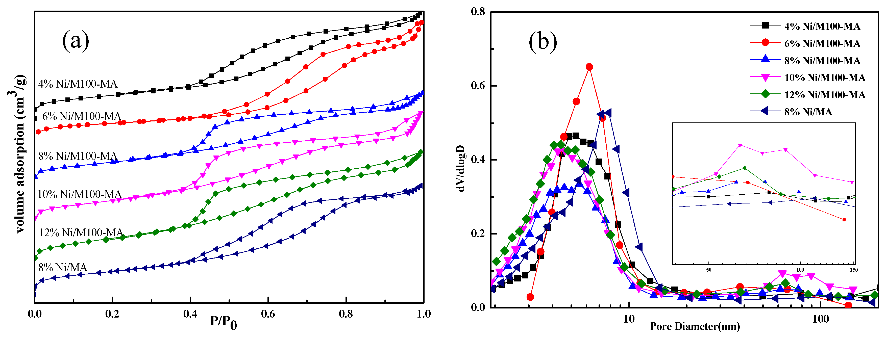
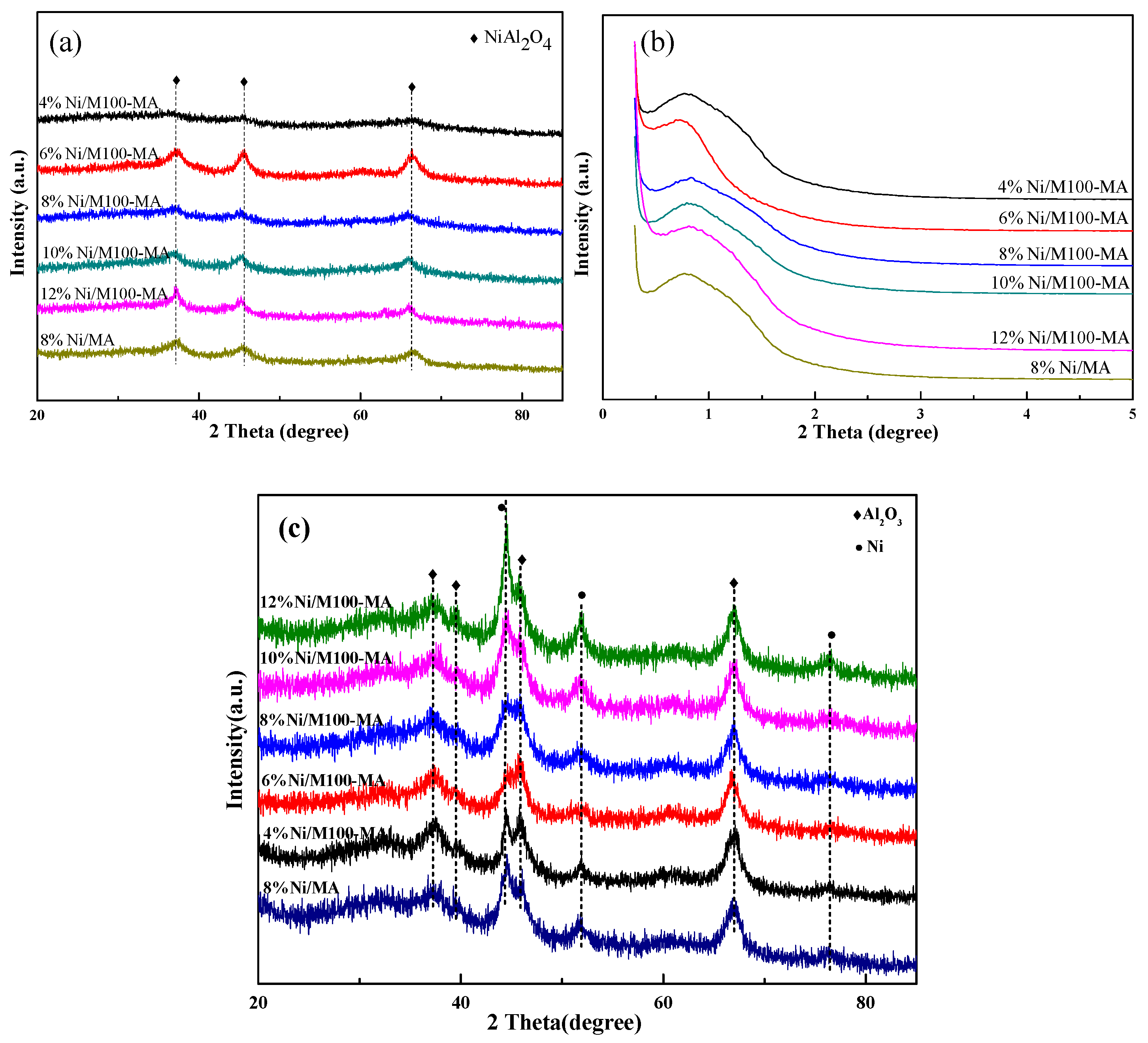
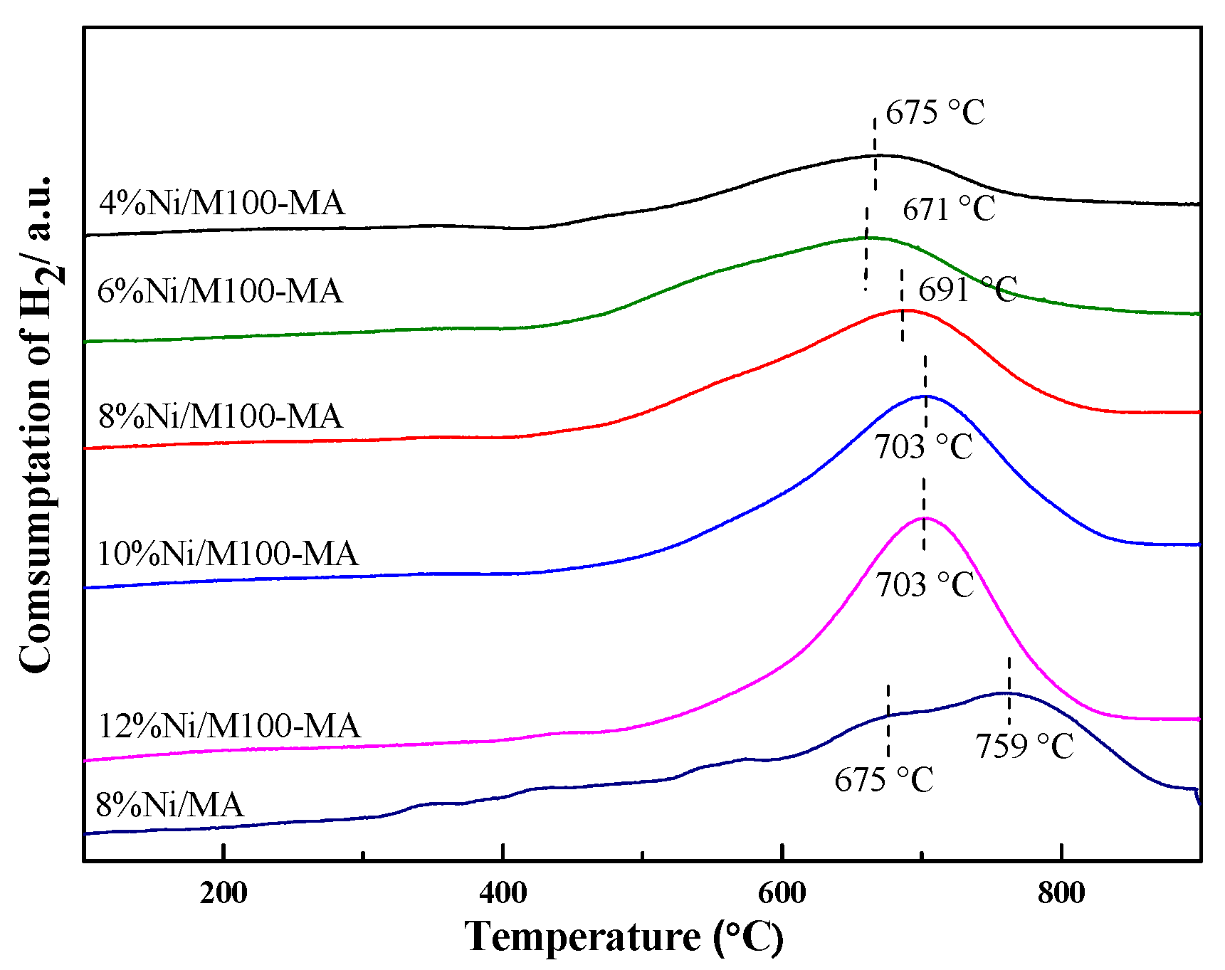
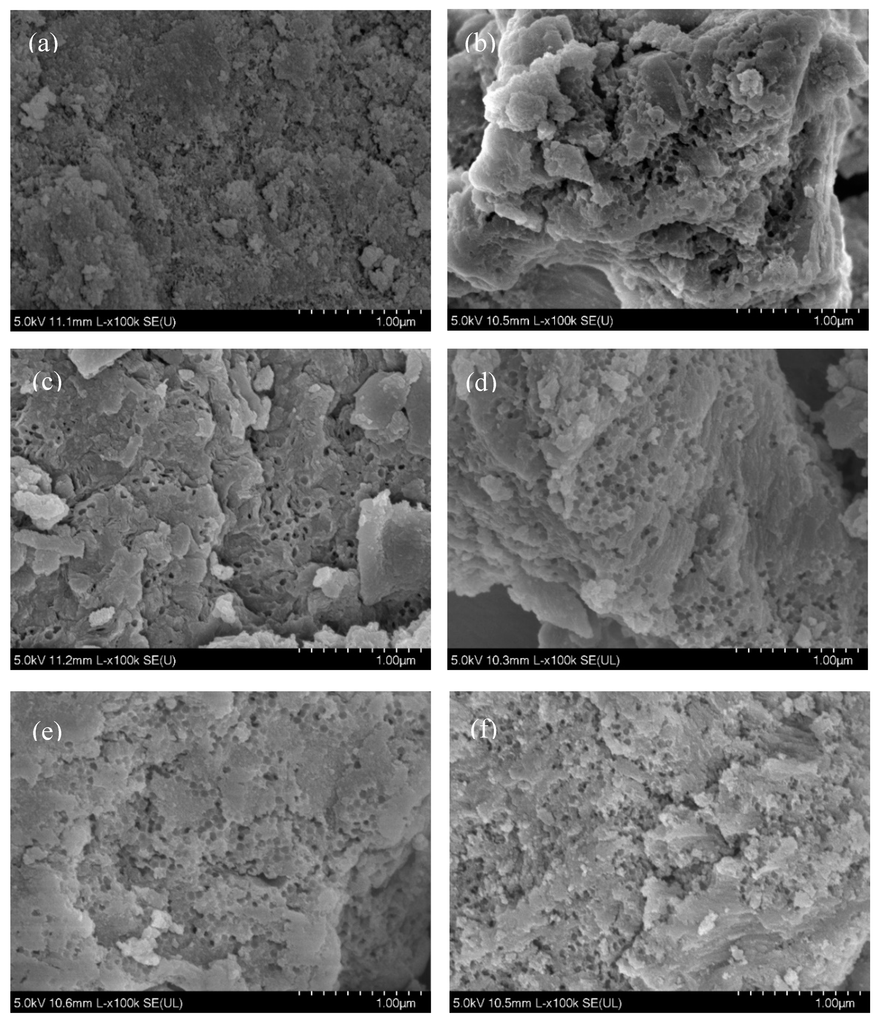
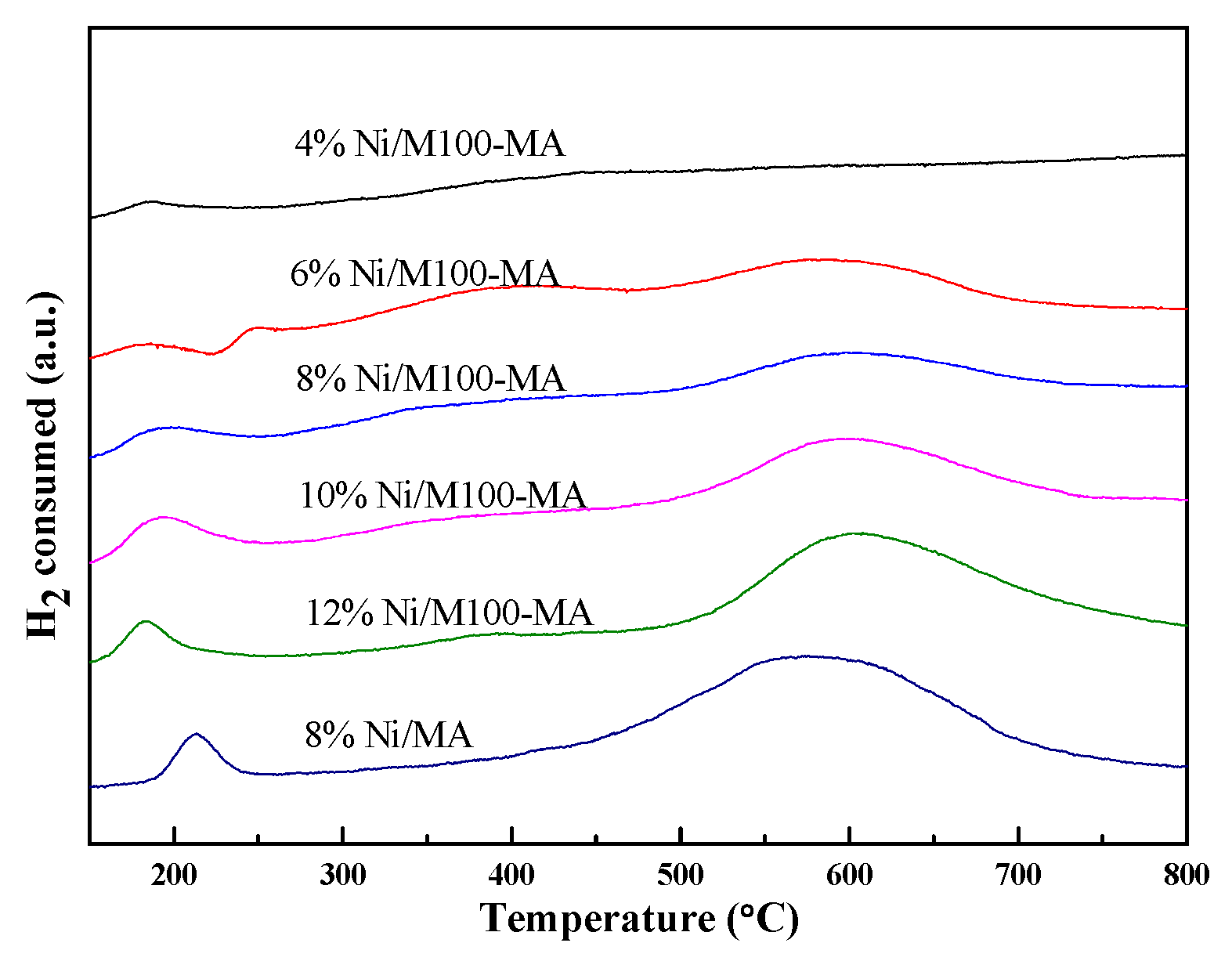
2.1. Fresh Catalysts Characterization

Figure 1a presents the N2 adsorption–desorption isotherm diagram for different nickel loadings catalysts. It is clearly seen that all catalysts exhibit a typical type IV adsorption isotherm, and the distinct H1-type hysteresis loop between P/P0 = 0.4 and 0.9 indicates the existence of a mesoporous structure. The isotherms of all bimodal porous catalysts showed a slight upward trend in the P/P0 > 0.9 area, which was macroporous adsorption according to the adsorption principle, indicating that a macroporous structure was formed. The pore size distribution in Figure 1b further demonstrates the existence of a bimodal porous structure. All catalysts showed protrusions after 60 nm, while only one sharp peak around 8 nm can be seen from 8% Ni/MA (mesoporous alumina), indicating that there were a large number of mesopores and a small number of macropores. As can be seen from Table 1, in addition to the 4% Ni/M100-MA catalyst, the specific surface area of the remaining catalysts increased as the nickel loading increased. Although nickel particles occupy the surface of the catalyst, they also provide the surface area. For 8% Ni/MA and 8% Ni/M100-MA, the BET (initials of Brunauer, Emmett and Teller) surface areas of 8 %Ni/MA and 8% Ni/M100-MA were 109.4 and 110.1 m2/g, respectively, and the pore volume was decreased from 0.24 to 0.18 cm3/g.
Figure 2a,b show the wide-angle and low-angle XRD spectra of the samples after calcination. It can be clearly seen from Figure 2a that there are diffraction peaks appearing at 2θ = 37.0°, 45.3°, and 66.4°. According to the PDF (10-0339) card, the diffraction peaks are attributed to NiAl2O4, which indicates that nickel species combine with alumina to form a new crystalline phase at high temperature. All samples have no obvious diffraction peaks of nickel species and alumina. The low-angle XRD spectrum is shown in Figure 2b. Diffraction peaks appear near 2θ = 1°, which are attributed to the (110) crystal plane of γ-Al2O3, indicating the presence of ordered mesopores in the sample. It is stated that a series of catalysts prepared have a large number of highly ordered mesoporous structures. The calcined samples were reduced by flowing 10%H2/Ar at 900 °C and new diffraction peaks can be clearly observed in the reduced XRD spectrum (Figure 2c), which are attributed to the (111), (200), and (220) crystal planes (44.5°, 51.8°, and 76.4°) of Ni and the (311), (222), (400), and (440) crystal planes (37.6°, 39.5°, 45.7°, and 66.6°) of Al2O3 according to the PDF (04-0850) and (29-0063) card. It can be calculated that the nickel particle size of 8%Ni/MA and 8%Ni/M100-MA is 6.5 and 5.5 nm, respectively. The nickel particle of 8%Ni/M100-MA is smaller than that of 8%Ni/MA.
H2-TPR is obtained to further understand the interaction between the metal and support of the catalyst. Figure 3 shows the H2-TPR curve of the sample after calcination. As can be seen, all catalysts have reduction peaks at high temperature. This is attributed to the reduction of Ni2+ to Ni0 in NiAl2O4, indicating that there is a strong metal–support interaction in the catalyst. With the increase in nickel loading, the reduction temperature increases gradually, and the area of the reduction peak also increases gradually, which contributes to the greater amount of NiAl2O4 formed. The relative H2 consumption amounts based on the 4%Ni/M100-MA of 4%Ni/M100-MA, 6%Ni/M100-MA, 8%Ni/M100-MA, 10%Ni/M100-MA, and 12%Ni/M100-MA are 1.00, 1.48, 1.83, 2.43, and 2.74, respectively, which means the amount of H2 consumption monotone increases with the nickel loading. The H2 consumption of 8%Ni/M100-MA is slightly lower than twice as much as that of 4%Ni/M100-MA, and the same regularity as 6%Ni/M100-MA and 12%Ni/M100-MA, indicating that the metal oxide in the samples was not completely reduced as the nickel loading increased. Compared to 759 °C of 8%Ni/MA, it is the macropores that preserved the weak interaction with metal Ni particles, resulting in a low reduction temperature [28]. The coexistence of low- and high-temperature peaks in 8%Ni/MA indicates the coexistence of a weak interaction and strong interaction.
The surface morphology of samples is displayed in Figure 4. It is clear that abundant macropores and mesopores are formed in M100-MA (in Figure 4a), indicating that the bimodal porous structure of the support was successfully prepared, and the structure was not damaged after impregnating the nickel content (in Figure 4). This result is in good agreement with that of the pore size distribution. Figure 5 shows the transmission electron microscope (TEM) images of 4%, 6%, 8%, 10%, and 12%Ni/M100-MA samples unreduced, respectively. Nickel-based particles in the samples can be faintly observed in Figure 5 that correspond to the dark spots [29]. There is no obvious metal agglomeration on the catalyst surface and Ni-based particles dispersed uniformly. No metal particles detached from the surface of the support were observed, which indirectly indicated that a strong interaction between the metal and support was formed, consistent with the H2-TPR results.
The TEM images of the reduced catalysts (Figure 6) clearly show the nickel particles and mesoporous alumina channels, confirming the construction of ordered mesoporous structured catalysts. It can be observed that there are Ni particles positioned inside the pore channels, evidencing that all the Ni particles were successfully confined by the support [30]. The average sizes of Ni particles were around 5–8 nm and the mean diameters of mesoporous alumina were about 6.6 nm which were consistent with the pore diameter shown in Table 1.

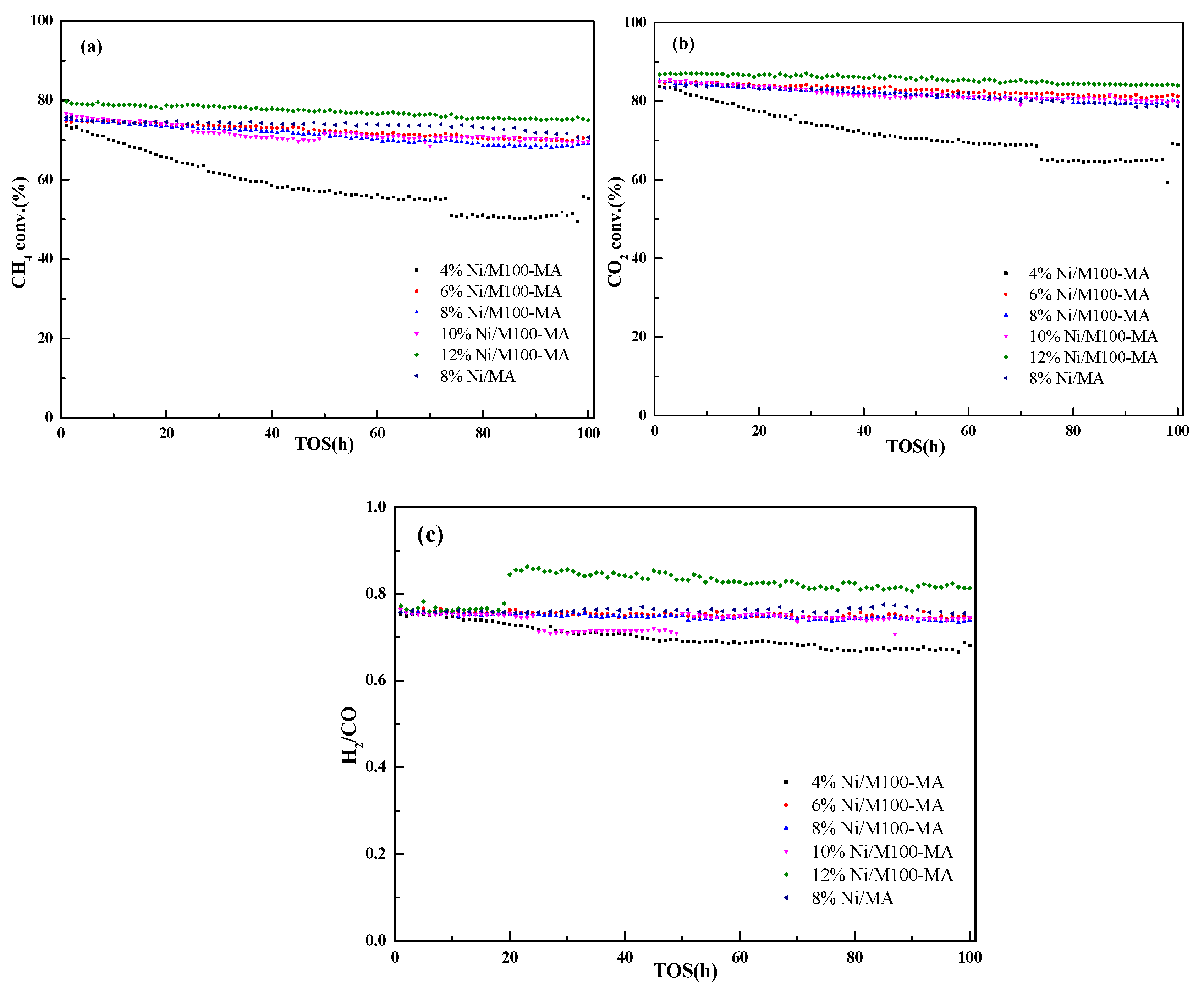
2.2. Catalytic Performance Test

To further determine the optimum nickel loading, all catalysts were evaluated for 100 h, and the results are shown in Figure 7. It can be seen that 4% Ni/M100-MA showed poor activity. After several hours of reaction, the conversion rate decreased drastically and there was obvious deactivation, indicating that the catalyst was poor both in stability and activity. The 12% Ni/M100-MA catalyst showed the best activity and stability. The conversion rate after 100 h was higher than that of other catalysts. The conversion of CH4 and CO2 reached 75.0% and 84.0%, respectively, which was higher than that of other previous studies (Table 2). The catalyst has a high nickel loading, a large specific surface area, and a strong interaction between the metal and the support, so that it has the best catalytic activity. It can be seen from Table 2 that as the nickel loading increases, the initial activity of catalysts becomes higher and higher, proportional to the nickel loading, and the loadings of 6%, 8%, and 10% were similar in conversion rate after 100 h of reaction, while the equilibrium conversion of CH4 and CO2 of the DRM reaction at 700 °C was 99.9% and 99.9%, respectively (according to Aspen simulation results and considering side effects). Meanwhile, only CO and H2 were detected by on-line GC analysis, showing the absolute selectivity to target products (>99%) [31].
Wang et al. [32] studied the Ni/γ-Al2O3 catalysts prepared using atomic layer deposition (ALD) as well as impregnation methods to investigate the moderate Ni loading. The results showed that the Ni loading has a vital impact on the catalytic performance and the best catalytic performance is shown in Table 2. Shen et al. [33] designed the Ni-based catalysts supported on nanosheet (S), nanofiber (F), and particle (P) alumina, and the Ni/Al2O3-F catalyst achieved the highest stability with no sign of deactivation. Zhang’s team [34] investigated a series of Ni/MgO-Al2O3 catalysts prepared by a simple two-step hydrothermal method and the better catalytic activity is displayed in Table 2.

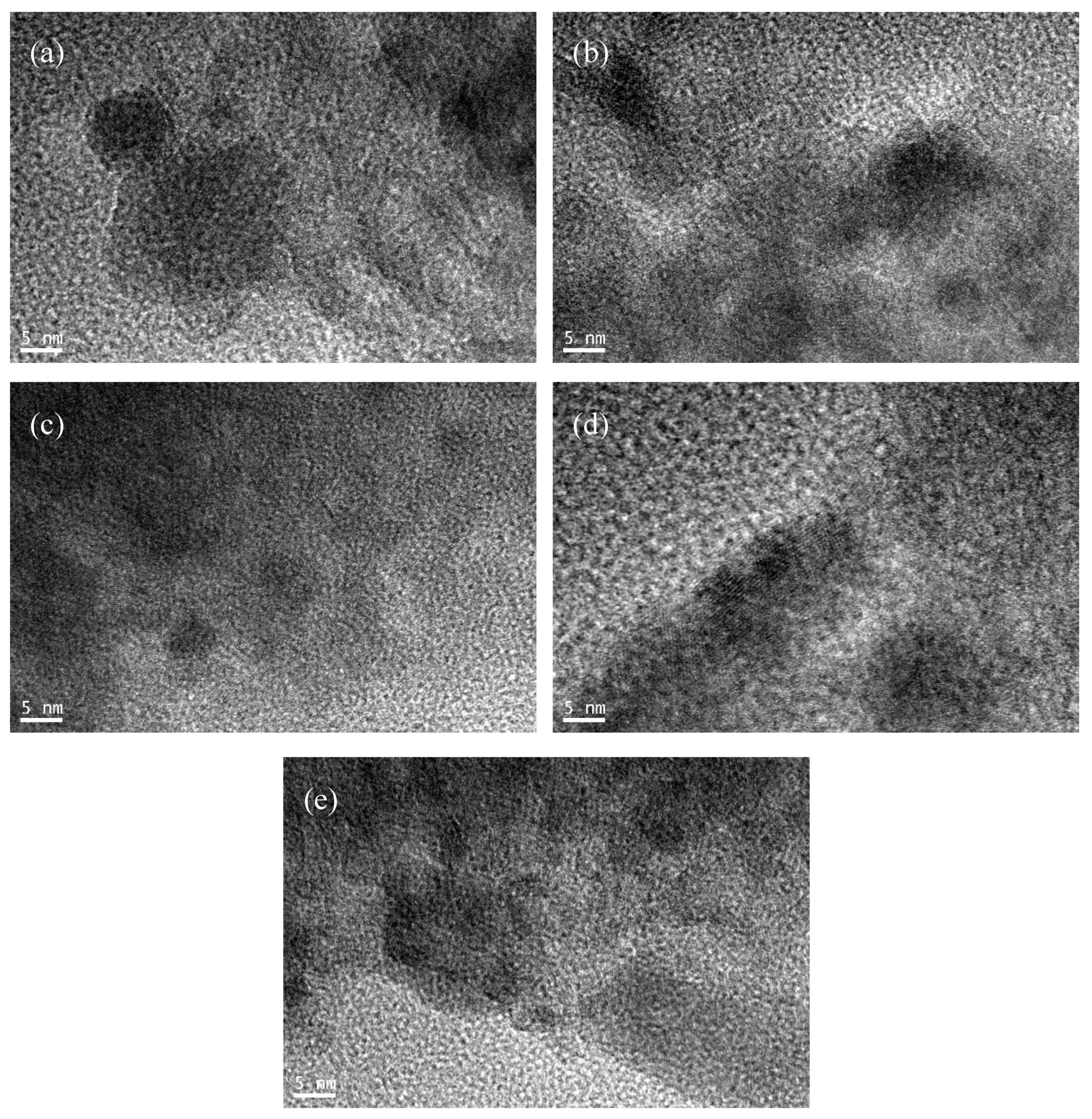
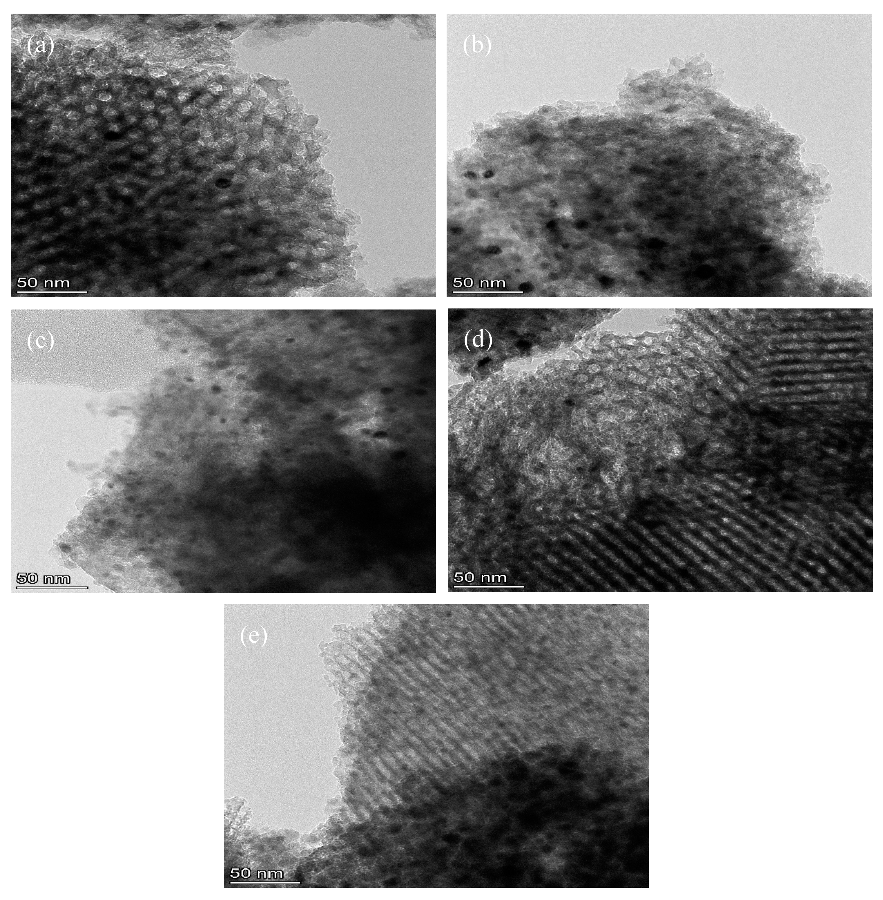
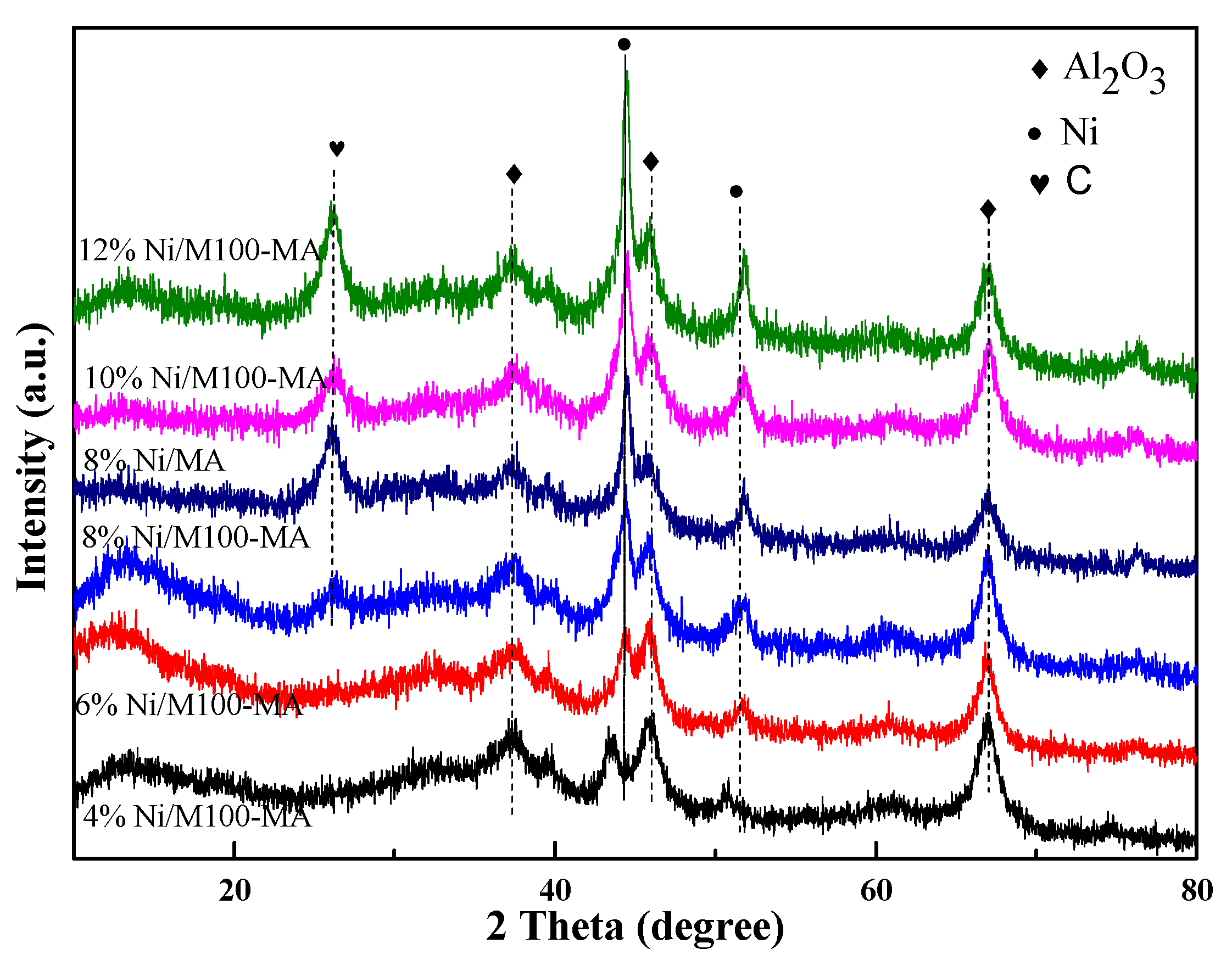
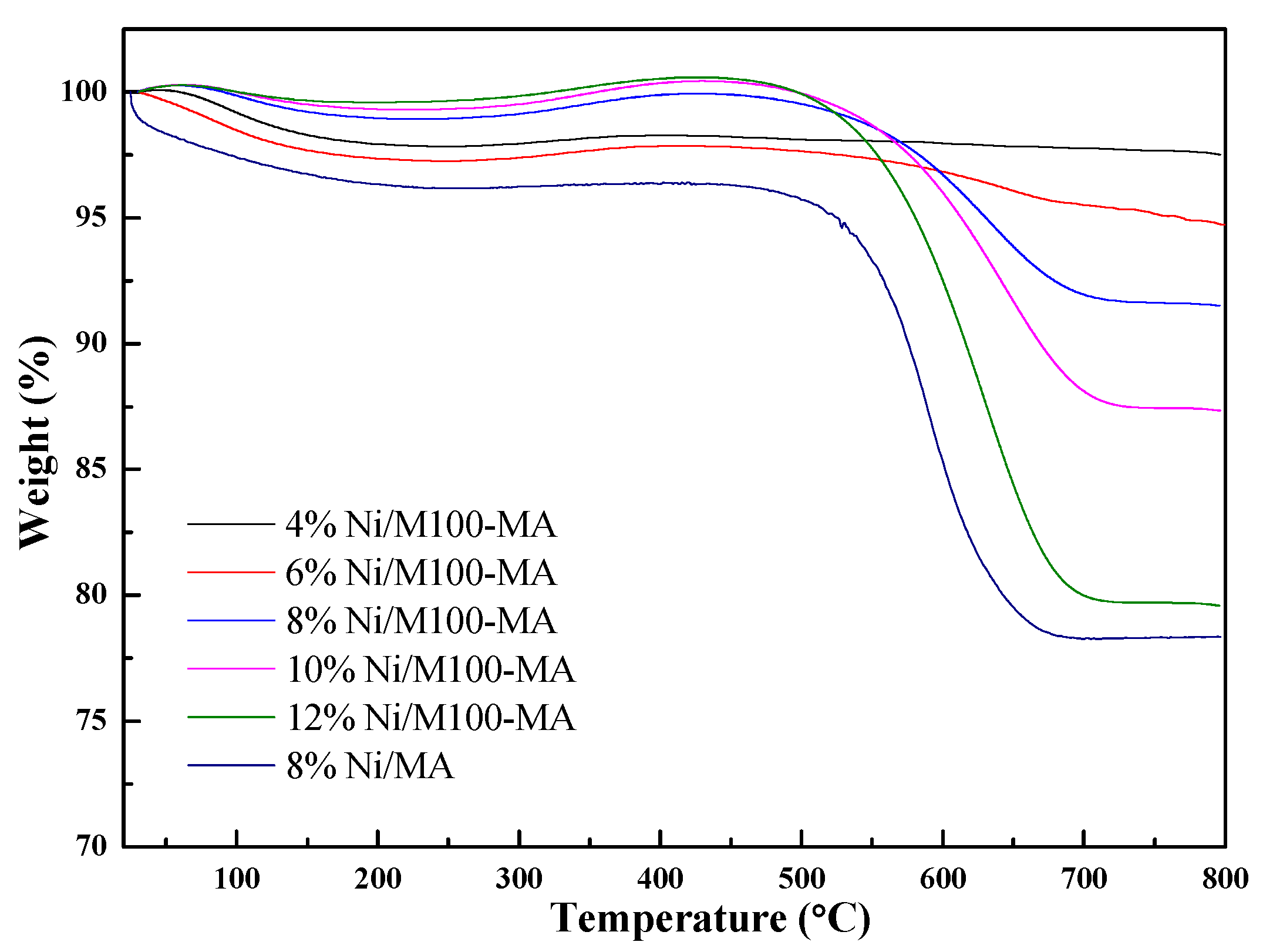
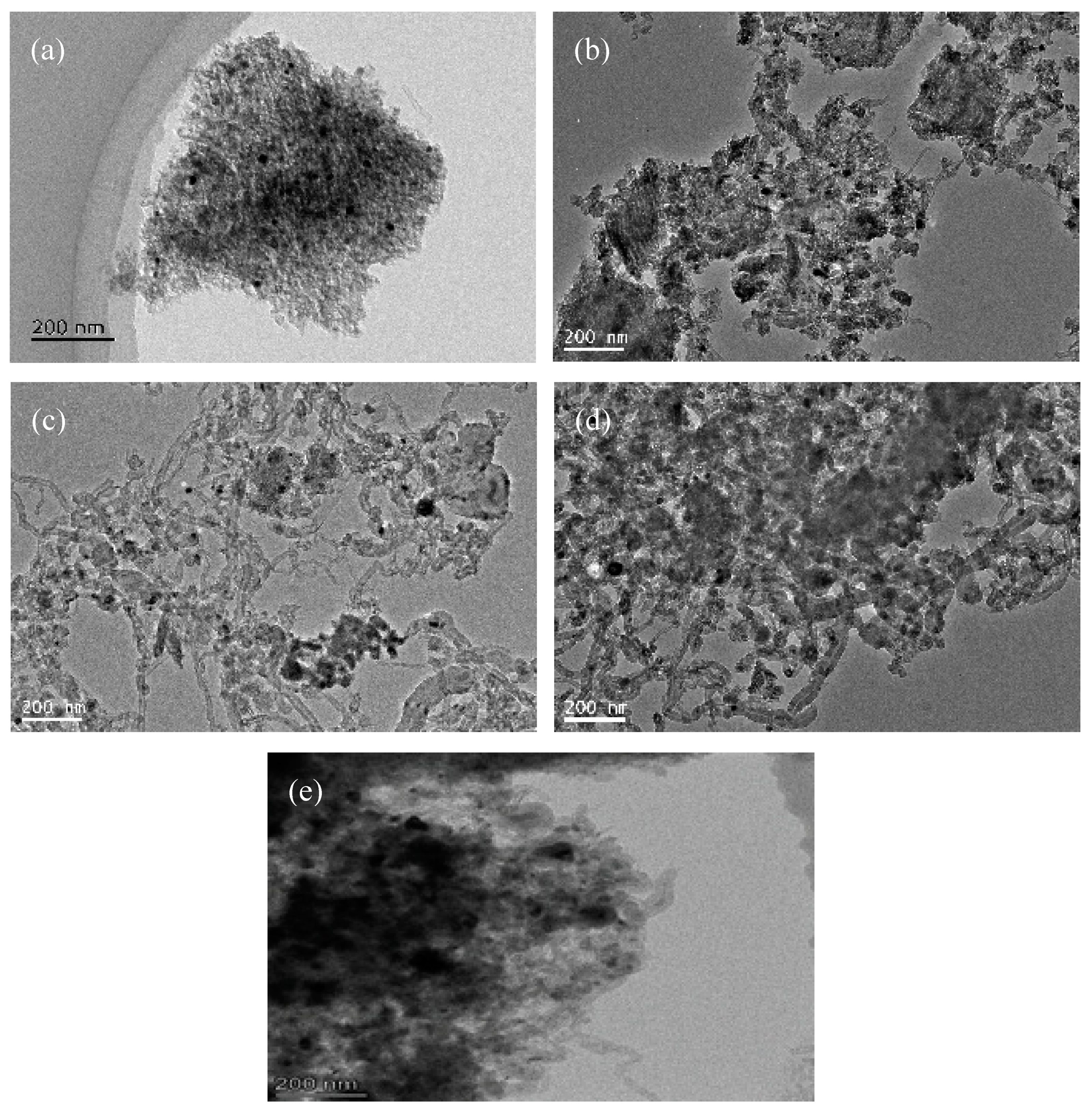
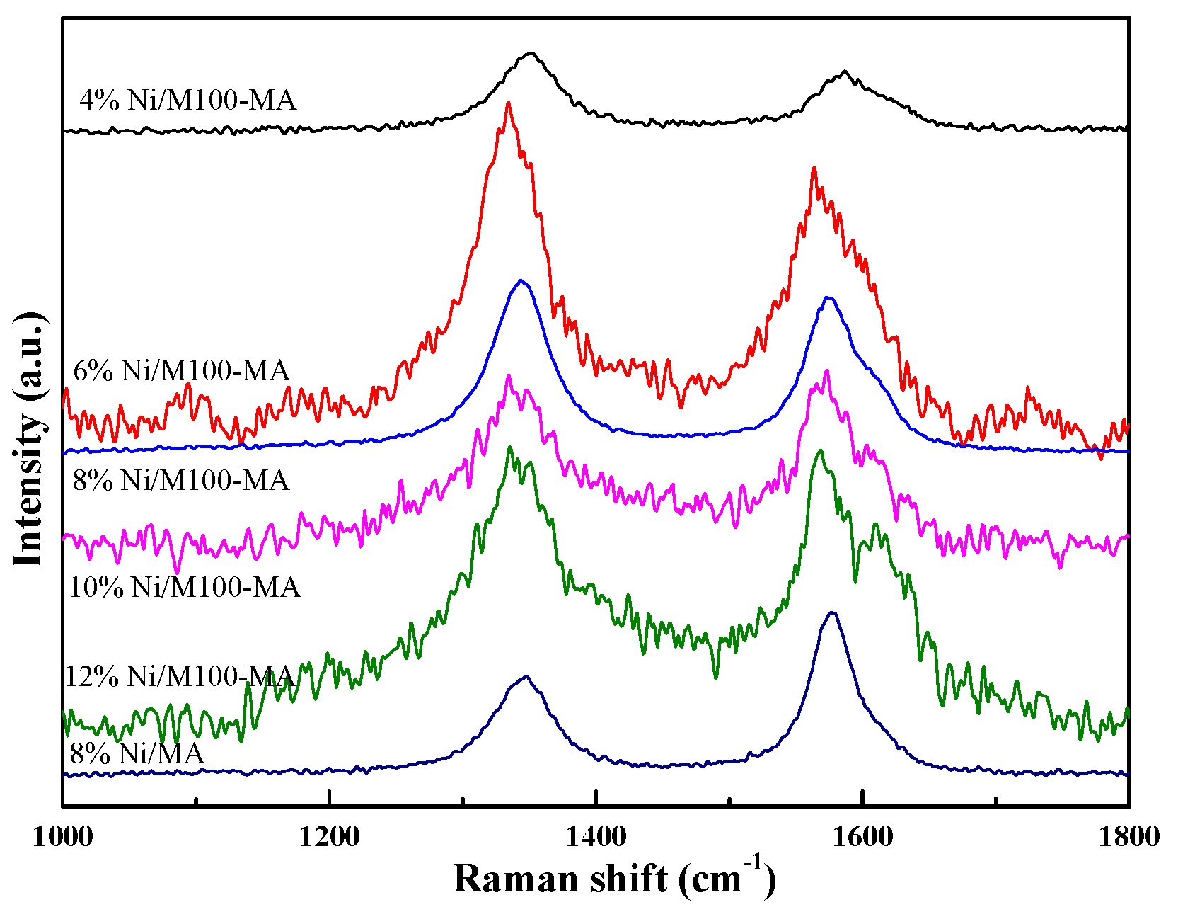
2.3. Spent Catalysts Characterization

In order to study the phase composition of spent catalysts with different Ni loadings after the reaction, the catalysts after reaction were characterized by XRD. The results are shown in Figure 8. All samples still showed the (111) and (200) crystal planes of Ni (44.5°, 51.8°), indicating that the metal Ni was not completely oxidized during the reaction. They also showed the (311), (400), and (440) crystal planes of Al2O3 (37.5°, 45.7°, and 66.6°). As is apparent from Figure 8, the intensity of the nickel diffraction peak increases as the nickel loading increases. The 8% Ni/M100-MA, 10% Ni/M100-MA, and 12% Ni/M100-MA catalysts show diffraction peaks of graphite carbon at 2θ = 26.3°, and the diffraction peaks intensity increases as the nickel loading increases, and this indicates that the catalyst with a large nickel loading tends to produce graphitic carbon [35] after the reaction. Further, the intensity of the graphite carbon diffraction peaks of 8%Ni/MA is higher than that of 8%Ni/M100-MA, indicating the 8%Ni/M100-MA is more conducive to anti-carbon.
In order to analyze the carbon deposition behavior of the catalysts, the catalysts after the reaction were characterized by TG in an air atmosphere to quantitatively detect the carbon content. As shown in Figure 9, different nickel loadings catalysts exhibited varying degrees of carbon deposition. As the nickel loading increases, the weight loss of carbon increases gradually, which indicates that the carbon deposition of the catalyst increases with the increase in nickel loading, which is consistent with the XRD characterization. From the TG curves, the main exothermic peak at 450–700 °C was due to the removal of the inert carbon which destroyed the active sites and deactivated catalysts. The amounts of the inert carbon on spent 8%Ni/MA and 8%Ni/M100-MA were quantitatively estimated to be 18.0% and 8.2%. TG results strongly suggest that 8%Ni/M100-MA has better coke resistance during the DRM reaction.
Many efforts have been reported to lower the carbon deposition. Some of them improved the synthesis method of the catalyst: Fang et al. [36] prepared the 12%Ni-Al2O3 catalyst by the evaporation-induced self-assembly method (EISA). After a 20-h stability test, the weight loss of 12%Ni-Al2O3-EISA was 28%, much lower than that of 12%Ni- Al2O3-IMP (impregnation method) which was 64%. Huang and his coworkers [37] reported that the 12%Ni@Al2O3 catalyst prepared by the inverse micro-emulsion technique performed with higher catalytic activity and better carbon deposition resistance than that of 12%Ni/Al2O3 (prepared by the impregnation method). The amount of carbon decreased to 15% compared with 54% of 12%Ni/Al2O3.
To further reveal the deposited carbon, the TEM images of spent catalysts after 100 h of reaction are displayed in Figure 10. It can be seen that the catalyst has a large number of carbon nanotubes generated. The formation of carbon nanotubes could weaken the interaction between the metallic Ni and support, making Ni particles separate from the mesoporous pores and migrate to the surface of the support, resulting in Ni particle agglomeration. There is a serious agglomeration of Ni particles in the 12%Ni/M100-MA catalyst (in Figure 10d), but it maintained good dispersion on the 6%Ni/M100-MA catalyst (in Figure 10a), which was attributed to the catalyst with a small Ni particle size and the strong metal–support interaction had stronger anti-carbon deposition performance [27].
TPH was attained to further determine the type of carbon deposition of the catalyst after the reaction. As shown in Figure 11, the main hydrogen-consuming peaks of the catalyst appear around 600 °C because of the hydrogenation of carbon nanotubes. As the nickel loading increases, the peak intensity and peak area are also constantly increasing, which indicates that the amount of carbon nanotubes is also increasing. It can be seen that the amount of carbon deposition increases with the increase in nickel loading, especially the number of carbon nanotubes, which is consistent with the result of the TG and XRD characterization. It can be also observed that there is more graphite carbon formed on the spent 8%Ni/MA than that on the spent 8%Ni/M100-MA.
The type of carbon species on the surface of catalysts can also be analyzed by Raman spectroscopy. Catalysts were measured with a 780 nm excitation source at a Raman shift of 1000 cm−1–1800 cm−1, as shown in Figure 12. The catalysts still have characteristic peaks: D peaks and G peaks, of carbon materials around 1300 cm−1 and 1580 cm−1. The larger ID/IG indicates the greater disorder of carbon materials. By calculation, the R (R = ID/IG ) values of the 4% Ni/M100-MA, 6% Ni/M100-MA, 8% Ni/M100-MA, 8% Ni/MA, 10% Ni/M100-MA, and 12% Ni/M100-MA catalysts were, respectively, 1.23, 1.23, 1.09, 0.75, 1.01, and 0.98, and it can be seen that as the nickel loading increases, the degree of graphitization of the formed carbon is gradually deepened, which is consistent with the TPH characterization results. Further, the carbon deposition species on the spent 8%Ni/MA exhibited a higher graphite degree than that on the spent 8%Ni/M100-MA.

3. Experimental Section

3.1. Catalyst Preparation and Characterization

Given amounts of templating agent P123, aluminum isopropoxide, and concentrated nitric acid were dissolved in absolute ethanol while stirring vigorously for 5 h. Then, an appropriate amount of polystyrene (PS) pellet (100 nm) was added to the above solution and stirring was continued for 5 min (mesoporous support was no PS pellet). The mixed solution was dried at 60 °C for 72 h, then the dried sample was calcined at 700 °C for 4 h in air atmosphere to obtain a bimodal porous structure support, which was named M100-MA. Then, it was impregnated on the M100-MA with a given amount of nickel nitrate, dried at 120 °C for 12 h, and calcined at 700 °C for 4 h in air atmosphere to obtain a bimodal porous structure catalyst, which was recorded as Ni/M100-MA [38]. Nickel loadings in this paper are mass percentages.
Powder X-ray diffractograms (XRD) of the catalysts were recorded by using Bruker’s D8 Advance X-ray diffractometer (Karlsruhe, Germany) (CuKα radiation) in the 3°–85° range (2°/min, 0.02° increment).
The N2 physical adsorption–desorption was analyzed by the JW-BK122F specific surface and aperture analyzer (Jingwei Gaobo, Beijing, China). Prior to testing, the sample was degassed under vacuum at 200 °C for 2 h to remove moisture and adsorbed impurities. The N2 adsorption–desorption isotherm was measured at 77 K. The specific surface area of the catalyst was calculated according to the BET equation, and the pore size distribution was calculated by the BJH (initials of Barrett, Joyner and Halenda) method.
H2 temperature programmed reduction (H2-TPR) was tested by the AutoChem II2920 automatic temperature programmed chemical adsorption instrument from Micromeritics, Norcross, GA, USA. The test conditions were as follows: The sample (50 mg) was heated up to 350 °C at a rate of 10 °C/min, and purged in 30 mL/min flowing helium for 1 h, reduced to 50 °C, and purged with 10% H2/Ar at a gas flow rate of 30 mL/min until the baseline was stable, then heated up to 900 °C at a rate of 10 °C/min, and the reduction curve was recorded simultaneously.
The transmission electron microscope (TEM) was tested with the Japanese JEM-2100F transmission electron microscope (Shojima, Tokyo, Japan), and the accelerating voltage was 200 kV. The scanning electron microscope (SEM) was tested with the Zeiss SUPRA55 scanning electron microscope (Jena, Germany), and the accelerating voltage was 3 kV.
Temperature programmed hydrogenation (TPH) was tested by the AutoChem II2920 automatic temperature programmed chemical adsorption instrument from Micromeritics, Norcross, GA, USA. The test conditions were as follows: A 40 mg spent catalyst was raised to the temperature of 150 °C at a rate of 10 °C/min, and purged with helium at a gas flow rate of 30 mL/min for 1 h, lowered to 50 °C, and switched to 10% H2/Ar, purged at a gas flow rate of 30 mL/min until the baseline was stable, then warmed up to 900 °C at a rate of 10 °C/min, and the reduction curve was recorded simultaneously.
Laser Raman spectroscopy (Raman) was carried out by HIRR high-resolution micro-Raman spectroscopy from Horiba, Paris, France. We preheated the Raman spectroscopy for 30 min before testing. The grinded sample was tested at 780 nm.
The carbon deposition resistance of catalysts was investigated by using thermogravimetric analysis (TG) (SETSYS16 comprehensive thermal analyzer, Setaram, Lyons, France). Catalysts were heated from room temperature to 800 °C in an air atmosphere at a heating rate of 10 °C/min.

3.2. Catalytic Test

Catalytic measurement was performed in a fixed bed reactor. The quartz reaction tube with an inner diameter of 6 mm was used as the reactor, and quartz sand (0.3 g) was to the catalyst (0.1 g) in reactor. The catalyst was uniformly mixed with quartz sand and charged into the middle of the quartz reaction tube, and then the quartz wool was filled in the front and rear positions of the catalyst for fixation. After that, we purged it with argon at a flow rate of 40 mL/min and checked the air tightness with soapy water. After that, we raised the temperature to the reduction temperature in argon atmosphere, then reduced the catalyst in a 40 mL/min flowing reducing gas (5%H2/95%N2). After reduction, we switched to the feed gas (CH4/CO2/Ar) for the reaction, and the reaction tail gas was detected on-line using GC-9560 chromatography (Shanghai, China) after removing water by cold trap condensation.
The reaction conditions were as follows: 0.1 g of catalyst (20–40 mesh), reduced at 700 °C for 2 h, CH4/CO2/Ar = 45/45/10, W/F = 1 g·h/mol, and the reaction temperature was 700 °C.

3.3. Results Calculation

During the experiment, Ar is used as the internal standard gas and does not participate in the reaction. The conversion rate can be calculated by the content of Ar in the tail gas. The calculation formula is as follows:
Conversion rate of CO2:
Conv . CO 2 ( % ) = A CO 2 in / A Ar in A CO 2 out / A Ar out A CO 2 in / A Ar in × 100 %
Conversion rate of CH4:
Conv . CH 4 ( % ) = A CH 4 in / A Ar in A CH 4 out / A Ar out A CH 4 in / A Ar in × 100 %
Ai represents the chromatographic peak area of component i.

4. Conclusions

In summary, a series of bimodal porous structure catalysts with different nickel loadings were prepared by the impregnation method. XRD, pore size distribution, and other characterizations indicate that the catalysts exhibit highly ordered mesoporous channels and a macroporours structure. As the nickel loading increases, the specific surface area of catalysts gradually increases, the interaction between the metal and support gradually increases, and the catalytic activity is also continuously enhanced. The carbon deposition amount and graphitization degree of catalysts increase with the increase in nickel loading, so that the carbon deposition resistance of catalysts gradually decreases. As the nickel loading doubled, the catalytic activity of the catalyst did not improve significantly, while the amount of carbon deposits increased a lot. Raman characterization showed that the catalyst with a lower Ni content has a lower degree of graphitization of carbon deposits formed after the DRM reaction, and the generated amorphous carbon is easily eliminated by CO2. Therefore, the more optimal nickel loadings are 6% and 8%, as the CH4 and CO2 conversion rates reached 69.7%, 81.2% and 69.1%, 79.8% after 100 h of reaction, respectively; the carbon content is just 5.3% and 8.3%, respectively, lower than that of the spent 8%Ni/MA (21.6%). The application of the bimodal porous structure in Ni-based catalysts was successful [37] and provided a promising result for highly active as well as stable Ni/Al2O3 catalysts for the DRM reaction.

Author Contributions

Conceptualization, Q.M. and J.S.; methodology, L.L. and Y.H.; formal analysis, S.M., X.G., J.Z. and H.F.; investigation, T.Z.; writing—original draft preparation, L.L. and Y.H.; writing—review and editing, Q.M., J.S. and T.-S.Z. All authors have read and agreed to the published version of the manuscript.

Funding

This research received no external funding.

Acknowledgments

The authors thank the financial support from National Natural Science Foundation of China (21766027), Ningxia Natural Science Foundation (2020AAC03023), the East-West Cooperation Project of Ningxia Key R & D Plan (2017BY063), Western youth scholar Talents Project of CAS (Grant No. XAB2016AW03) and the Foundation of State Key Laboratory of High-efficiency Coal Utilization and Green Chemical Engineering (Grant No. 2019-KF-11).

Conflicts of Interest

The authors declare no conflict of interest.

References

  1. Yide, X.U.; Bao, X.; Lin, L. Direct conversion of methane under nonoxidative conditions. J. Catal. 2003, 216, 386–395. [Google Scholar]
  2. Lin, Q.; Zhang, Q.; Yang, G.; Chen, Q.; Li, J.; Wei, Q.; Tan, Y.; Wan, H.; Tsubaki, N. Insights into the promotional roles of palladium in structure and performance of cobalt-based zeolite capsule catalyst for direct synthesis of C5-C11 iso-paraffins from syngas. J. Catal. 2016, 344, 378–388. [Google Scholar] [CrossRef] [Green Version]
  3. Behrens, M.; Studt, F.; Kasatkin, I.; Kühl, S.; Hävecker, M.; Abild-Pedersen, F.; Zander, S.; Girgsdies, F.; Kurr, P.; Kniep, B.L.; et al. The active site of methanol synthesis over Cu/ZnO/Al2O3 industrial catalysts. Science 2012, 336, 893–897. [Google Scholar] [CrossRef]
  4. Wysocka, I.; Hupka, J.; Rogala, A. Catalytic Activity of Nickel and Ruthenium-Nickel Catalysts Supported on SiO2, ZrO2, Al2O3, and MgAl2O4 in a Dry Reforming Process. Catalysts 2019, 9, 540. [Google Scholar] [CrossRef] [Green Version]
  5. Lu, Y.; Jiang, S.; Wang, S.; Zhao, Y.; Ma, X. Effect of the addition of Ce and Zr over a flower-like NiO-MgO (111) solid solution for CO2 reforming of methane. J. CO2 Util. 2018, 26, 123–132. [Google Scholar] [CrossRef]
  6. Kim, A.R.; Lee, H.Y.; Cho, J.M.; Choi, J.H.; Bae, J.W. Ni/M-Al2O3 (M = Sm, Ce or Mg) for combined steam and CO2 reforming of CH4 from coke oven gas. J. CO2 Util. 2017, 21, 211–218. [Google Scholar] [CrossRef]
  7. Wei, Q.; Yang, G.; Gao, X.; Yamane, N.; Zhang, P.; Liu, G.; Tsubaki, N. Ni/Silicalite-1 coating being coated on SiC foam: A tailor-made monolith catalyst for syngas production using a combined methane reforming process. Chem. Eng. J. 2017, 327, 465–473. [Google Scholar] [CrossRef]
  8. Kawi, S.; Kathiraser, Y.; Ni, J.; Oemar, U.; Li, Z.; Saw, E.T. Progress in Synthesis of Highly Active and Stable Nickel-Based Catalysts for Carbon Dioxide Reforming of Methane. ChemSusChem 2015, 8, 3556–3575. [Google Scholar] [CrossRef]
  9. Li, H.; Wang, J. Study on CO2 reforming of methane to syngas over Al2O3–ZrO2 supported Ni catalysts prepared via a direct sol–gel process. Chem. Eng. Sci. 2004, 59, 4861–4867. [Google Scholar] [CrossRef]
  10. Carvalho, D.C.; de Souza, H.S.; Josué Filho, M.; Oliveira, A.C.; Campos, A.; Milet, É.R.; de Sousa, F.F.; Padron-Hernandez, E.; Oliveira, A.C. A study on the modification of mesoporous mixed oxides supports for dry reforming of methane by Pt or Ru. Appl. Catal. B Environ. 2014, 473, 132–145. [Google Scholar] [CrossRef]
  11. Köpfle, N.; Götsch, T.; Grünbacher, M.; Carbonio, E.A.; Hävecker, M.; Knop-Gericke, A.; Schlicker, L.; Doran, A.; Kober, D.; Gurlo, A.; et al. Zirconium-assisted activation of palladium to boost syngas production by methane dry reforming. Angew. Chem. Int. Ed. 2018, 57, 14613–14618. [Google Scholar] [CrossRef] [PubMed]
  12. Yentekakis, I.V.; Goula, G.; Hatzisymeon, M.; Betsi-Argyropoulou, I.; Botzolaki, G.; Kousi, K.; Kondarides, D.I.; Taylor, M.J.; Parlett, C.M.; Osatiashtiani, A.; et al. Effect of support oxygen storage capacity on the catalytic performance of Rh nanoparticles for CO2 reforming of methane. Appl. Catal. B Environ. 2019, 243, 490–501. [Google Scholar] [CrossRef] [Green Version]
  13. Das, S.; Shah, M.; Gupta, R.K.; Bordoloi, A. Enhanced dry methane reforming over Ru decorated mesoporous silica and its kinetic study. J. CO2 Util. 2019, 29, 240–253. [Google Scholar] [CrossRef]
  14. Richardson, J.T.; Paripatyadar, S.A. Carbon dioxide reforming of methane with supported rhodium. Appl. Catal. 1990, 61, 293–309. [Google Scholar] [CrossRef]
  15. Boukha, Z.; Kacimi, M.; Pereira, M.F.; Faria, J.L.; Figueiredo, J.L.; Ziyad, M. Methane dry reforming on Ni loaded hydroxyapatite and fluoroapatite. Appl. Catal. A Gen. 2007, 317, 299–309. [Google Scholar] [CrossRef]
  16. Wu, Z.; Yang, B.; Miao, S.; Liu, W.; Xie, J.; Lee, S.; Pellin, M.J.; Xiao, D.; Su, D.; Ma, D. Lattice strained Ni-Co alloy as a high-performance catalyst for catalytic dry reforming of methane. ACS Catal. 2019, 9, 2693–2700. [Google Scholar] [CrossRef]
  17. Yan, X.; Hu, T.; Liu, P.; Li, S.; Zhao, B.; Zhang, Q.; Jiao, W.; Chen, S.; Wang, P.; Lu, J.; et al. Highly efficient and stable Ni/CeO2-SiO2 catalyst for dry reforming of methane: Effect of interfacial structure of Ni/CeO2 on SiO2. Appl. Catal. B Environ. 2019, 246, 221–231. [Google Scholar] [CrossRef]
  18. Kalai, D.Y.; Stangeland, K.; Jin, Y.; Tucho, W.M.; Yu, Z. Biogas dry reforming for syngas production on La promoted hydrotalcite-derived Ni catalysts. Int. J. Hydrog. Energy 2018, 43, 19438–19450. [Google Scholar] [CrossRef]
  19. Hou, Z.; Chen, P.; Fang, H.; Zheng, X.; Yashima, T. Production of synthesis gas via methane reforming with CO on noble metals and small amount of noble-(Rh-) promoted Ni catalysts. Int. J. Hydrog. Energy 2006, 31, 555–561. [Google Scholar] [CrossRef]
  20. Feng, X.; Liu, J.; Zhang, P.; Zhang, Q.; Xu, L.; Zhao, L.; Song, X.; Gao, L. Highly coke resistant Mg-Ni/Al2O3 catalyst prepared via a novel magnesiothermic reduction for methane reforming catalysis with CO2: The unique role of Al-Ni intermetallics. Nanoscale 2019, 11, 1262–1272. [Google Scholar] [CrossRef]
  21. Movasati, A.; Alavi, S.M.; Mazloom, G. Dry reforming of methane over CeO2-ZnAl2O4 supported Ni and Ni-Co nano-catalysts. Fuel 2019, 236, 1254–1262. [Google Scholar] [CrossRef]
  22. Li, Z.; Wang, Z.; Kawi, S. Sintering and coke resistant core/yolk shell catalyst for hydrocarbon reforming. ChemCatChem 2019, 11, 202–224. [Google Scholar] [CrossRef]
  23. Fan, X.; Liu, Z.; Zhu, Y.A.; Tong, G.; Zhang, J.; Engelbrekt, C.; Ulstrup, J.; Zhu, K.; Zhou, X. Tuning the composition of metastable CoxNiyMg100−x−y(OH)(OCH3) nanoplates for optimizing robust methane dry reforming catalyst. J. Catal. 2015, 330, 106–119. [Google Scholar] [CrossRef]
  24. Zhou, H.; Zhang, T.; Sui, Z.; Zhu, Y.A.; Han, C.; Zhu, K.; Zhou, X. A single source method to generate Ru-Ni-MgO catalysts for methane dry reforming and the kinetic effect of Ru on carbon deposition and gasification. Appl. Catal. B Environ. 2018, 233, 143–159. [Google Scholar] [CrossRef]
  25. Akri, M.; Zhao, S.; Li, X.; Zang, K.; Lee, A.F.; Isaacs, M.A.; Xi, W.; Gangarajula, Y.; Luo, J.; Ren, Y.; et al. Atomically dispersed nickel as coke-resistant active sites for methane dry reforming. Nat. Commun. 2019, 10, 5181. [Google Scholar] [CrossRef] [Green Version]
  26. Wang, H.Y.; Ruckenstein, E. Ruckenstein. Carbon dioxide reforming of methane to synthesis gas over supported rhodium catalysts: The effect of support. Appl. Catal. A Gen. 2000, 204, 143–152. [Google Scholar] [CrossRef]
  27. Sepehri, S.; Rezaei, M. Preparation of highly active nickel catalysts supported on mesoporous nanocrystalline γ-Al2O3 for methane autothermal reforming. Chem. Eng. Technol. 2015, 38, 1637–1645. [Google Scholar] [CrossRef]
  28. Ma, Q.; Han, Y.; Wei, Q.; Makpal, S.; Gao, X.; Zhang, J.; Zhao, T.S. Stabilizing Ni on bimodal mesoporous-macroporous alumina with enhanced coke tolerance in dry reforming of methane to syngas. J. CO2 Util. 2020, 35, 288–297. [Google Scholar] [CrossRef]
  29. Li, B.; Luo, Y.; Li, B.; Yuan, X.; Wang, X. Catalytic performance of iron-promoted nickel-based ordered mesoporous alumina FeNiAl catalysts in dry reforming of methane. Fuel Process. Technol. 2019, 193, 348–360. [Google Scholar] [CrossRef]
  30. Wang, F.; Han, B.; Zhang, L.; Xu, L.; Yu, H.; Shi, W. CO2 reforming with methane over small-sized Ni@SiO2 catalysts with unique features of sintering-free and low carbon. Appl. Catal. B Environ. 2018, 235, 26–35. [Google Scholar] [CrossRef]
  31. Zhao, Y.; Kang, Y.; Li, H.; Li, H. CO2 conversion to synthesis gas via DRM on the durable Al2O3/Ni/Al2O3 sandwich catalyst with high activity and stability. Green Chem. 2018, 10, 1039. [Google Scholar] [CrossRef]
  32. Wang, G.; Luo, F.; Cao, K.; Zhang, Y.; Li, J.; Zhao, F.; Chen, R.; Hong, J. Effect of Ni content of Ni/γ-Al2O3 catalysts prepared by atomic layer deposition method on CO2 reforming of methane. Energy Technol. 2019, 7, 1800359. [Google Scholar] [CrossRef]
  33. Shen, D.; Huo, M.; Li, L.; Lyu, S.; Wang, J.; Wang, X.; Zhang, Y.; Li, J. Effects of alumina morphology on dry reforming of methane over Ni/Al2O3 catalysts. Catal. Sci. Technol. 2020, 10, 510. [Google Scholar] [CrossRef]
  34. Zhang, L.; Zhang, Q.; Liu, Y.; Zhang, Y. Dry reforming of methane over Ni/MgO-Al2O3 catalysts prepared by two-step hydrothermal method. Appl. Surf. Sci. 2016, 389, 25–33. [Google Scholar] [CrossRef]
  35. Guczi, L.; Stefler, G.; Geszti, O.; Sajó, I.; Pászti, Z.; Tompos, A.; Schay, Z. Methane dry reforming with CO2: A study on surface carbon species. Appl. Catal. A Gen. 2010, 375, 236–246. [Google Scholar] [CrossRef]
  36. Fang, X.; Peng, C.; Peng, H.; Liu, W.; Xu, X.; Wang, X.; Li, C.; Zhou, W. Methane Dry Reforming over Coke-Resistant Mesoporous Ni-Al2O3 Catalysts Prepared by Evaporation-Induced Self-Assembly Method. ChemCatChem 2015, 7, 3753–3762. [Google Scholar] [CrossRef]
  37. Huang, Q.; Fang, X.; Cheng, Q.; Li, Q.; Xu, X.; Xu, L.; Liu, W.; Gao, Z.; Zhou, W.; Wang, X. Synthesis of Highly Active and Stable Ni@Al2O3 Embedded Catalyst for Methane Dry Reforming: On the Confinement Effect of Al2O3 Shells for Ni Nanoparticles. ChemCatChem 2017, 9, 3563–3572. [Google Scholar] [CrossRef]
  38. Yuan, Q.; Yin, A.X.; Luo, C.; Sun, L.D.; Zhang, Y.W.; Duan, W.T.; Liu, H.C.; Yan, C.H. Facile Synthesis for Ordered Mesoporous γ-Aluminas with High Thermal Stability. J. Am. Chem. Soc. 2008, 130, 3465–3472. [Google Scholar] [CrossRef]
Figure 1. N2 adsorption–desorption isotherms (a) and pore size distribution (b).
Catalysts 10 01220 g001
Figure 2. Wide-angle XRD patterns (a) and low-angle XRD patterns (b) of the calcined samples; (c) wide-angle XRD patterns of the reduced samples.
Catalysts 10 01220 g002
Figure 3. H2-TPR profiles of the samples.
Catalysts 10 01220 g003
Figure 4. Scanning electron microscope (SEM) images of M100-MA (a), 4%Ni/M100-MA (b), 6%Ni/M100-MA (c), 8% Ni/M100-MA (d), 10% Ni/M100-MA (e), and 12% Ni/M100-MA (f).
Catalysts 10 01220 g004
Figure 5. TEM images of 4% Ni/M100-MA (a), 6% Ni/M100-MA (b), 8% Ni/M100-MA (c), 10% Ni/M100-MA (d), and 12% Ni/M100-MA (e).
Catalysts 10 01220 g005
Figure 6. TEM images of reduced catalysts. 4 % Ni/M100-MA (a), 6 % Ni/M100-MA (b), 8 % Ni/M100-MA (c), 10 % Ni/M100-MA (d), and 12 % Ni/M100-MA (e).
Catalysts 10 01220 g006
Figure 7. Evaluation of CH4 conversion (a), CO2 conversion (b), and H2/CO (c) over catalysts during the dry reforming of methane (DRM) reaction. Reaction conditions: CH4/CO2/Ar = 45/45/10, W/F = 1 g·h/mol, T = 700 °C, TOS = 100 h.
Catalysts 10 01220 g007
Figure 8. XRD patterns of the spent catalysts.
Catalysts 10 01220 g008
Figure 9. TG profiles of the spent catalysts.
Catalysts 10 01220 g009
Figure 10. TEM images of spent catalysts. 4% Ni/M100-MA (a), 6% Ni/M100-MA (b), 8% Ni/M100-MA (c), 10% Ni/M100-MA (d), and 12% Ni/M100-MA (e).
Catalysts 10 01220 g010
Figure 11. TPH profiles of the spent catalysts.
Catalysts 10 01220 g011
Figure 12. Raman spectra of the spent catalysts.
Catalysts 10 01220 g012
Table 1. Surface area and pore parameters of the samples.
SampleBET Surface (m2/g)Pore Volume (cm3/g)Pore Diameter (nm)
4% Ni/M100-MA109.40.215.3
6% Ni/M100-MA106.50.236.2
8% Ni/M100-MA110.10.185.5
10% Ni/M100-MA128.50.234.6
12% Ni/M100-MA142.50.234.4
8% Ni/MA109.40.247.8
Table 2. Comparison with previous literature.
CatalystTemperature (°C)Cat.Weight (g)a TOS (h)Conv. (%)Ref.
CH4CO2
Ni1.6/γ-Al2O37000.13555.864.3[32]
Ni/Al2O3-F7500.2108082.5[33]
Ni/MgO-Al2O3(15%)6500.1105264[34]
12%Ni-M100-MA7000.110075.084.0This work
a TOS means time on stream.
Publisher’s Note: MDPI stays neutral with regard to jurisdictional claims in published maps and institutional affiliations.

