
Specification and Description Language Models Automatic Execution in a High-Performance Environment

Abstract
:1. Introduction
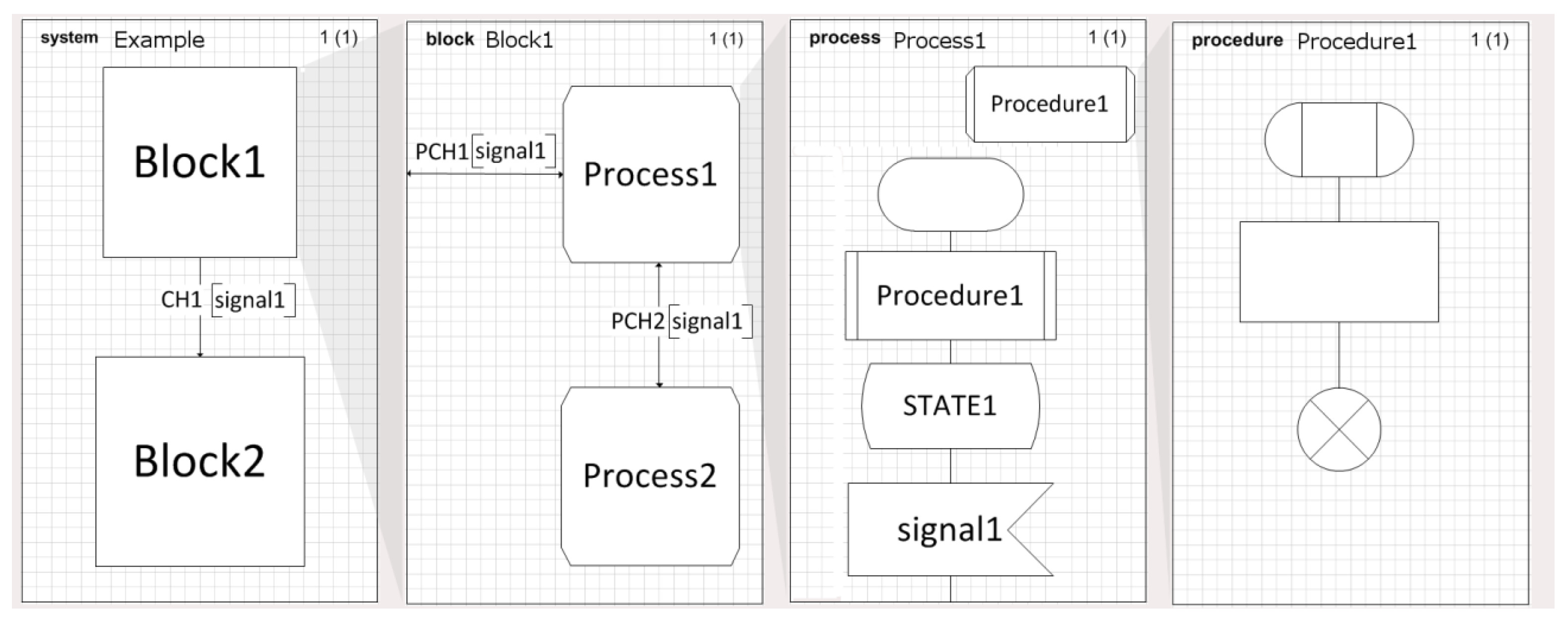
2. Our Approach: Specification and Description Language
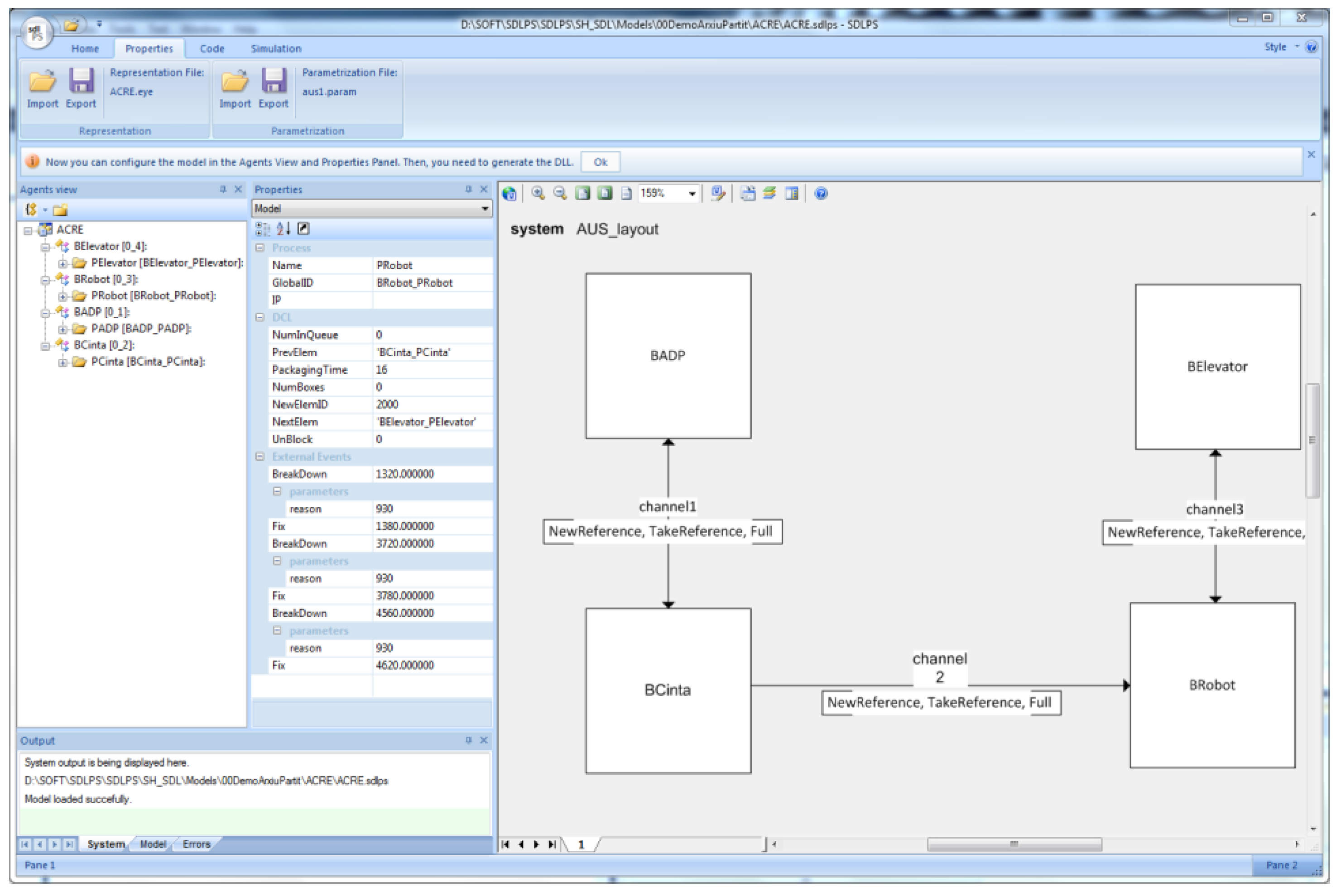
2.1. SDLPS
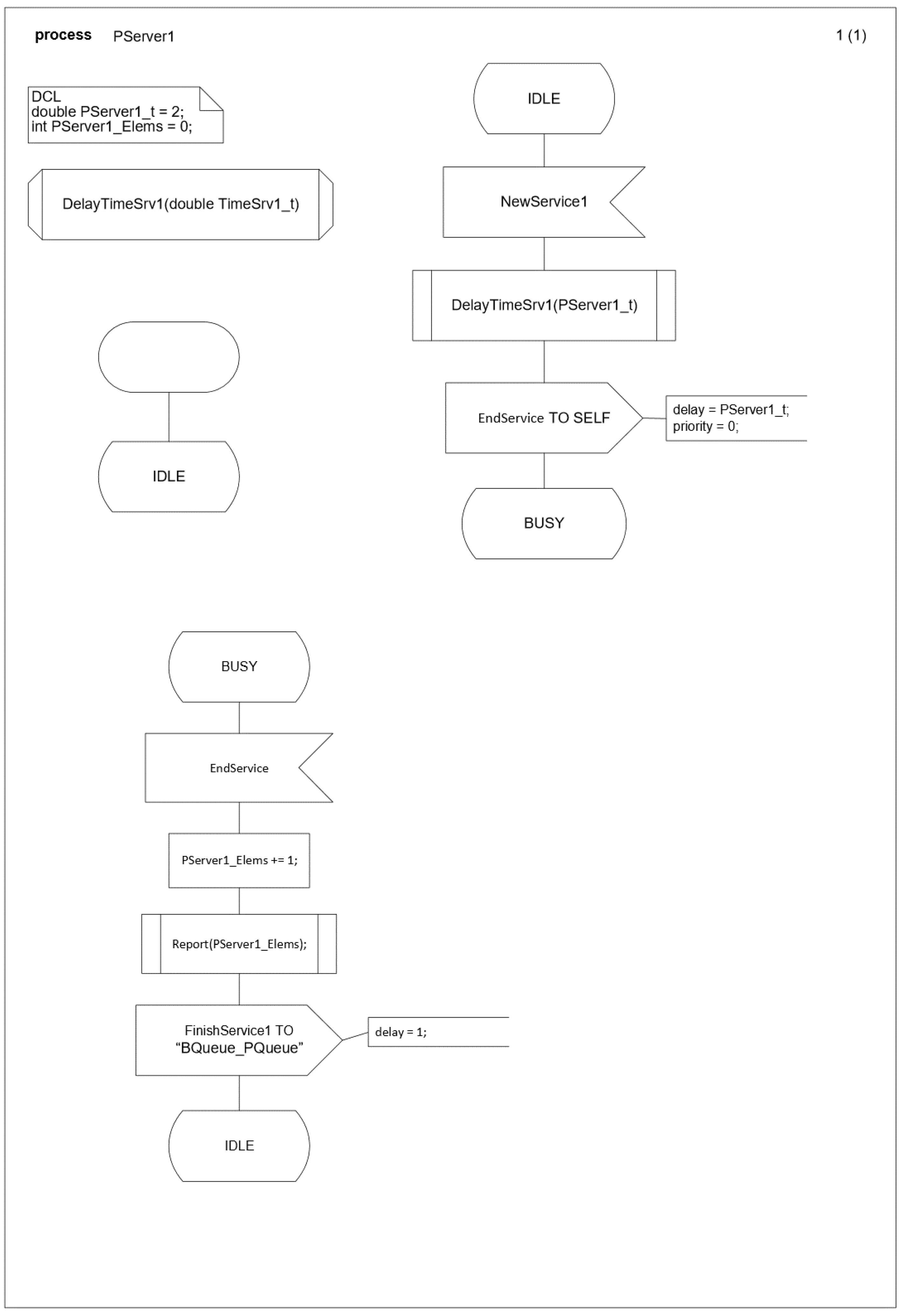
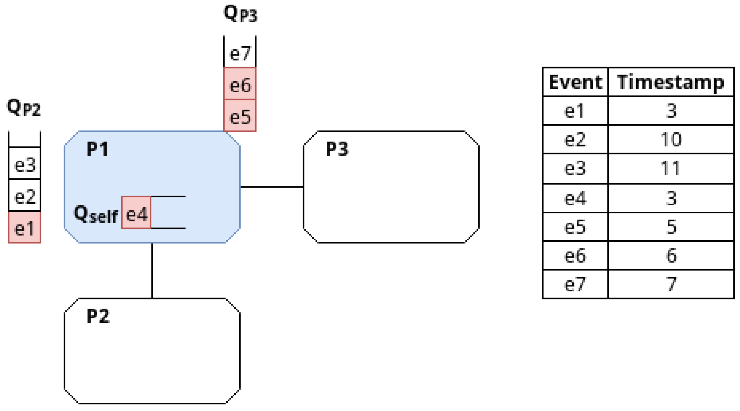
2.1.1. SDLPS Time Management
2.1.2. Input and Output Variables
          <!--Procedures definition.-->
          <procedures>
             <procedure id=“1” name=“DelayTimeSrv1” implementation=“”>
             <params>
                  <param name=“TimeSrv1_t” type=“double” defvalue=“” ref=“yes”></param>
               </params>
               <body>
                  <task id=“1” name=“”>TimeSrv1_t=60;</task>
               </body>
             </procedure>
          </procedures>
          <procedurecall id=“2” name=“DelayTimeSrv1”>
             <param name=“TimeSrv1_t” value=“PServer1_t”></param>
          </procedurecall>
3. Generating the HPC Code
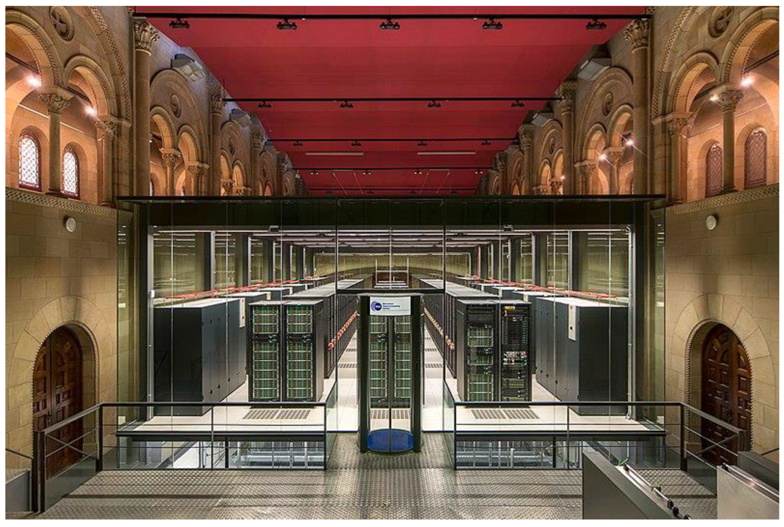
3.1. The Marenostrum
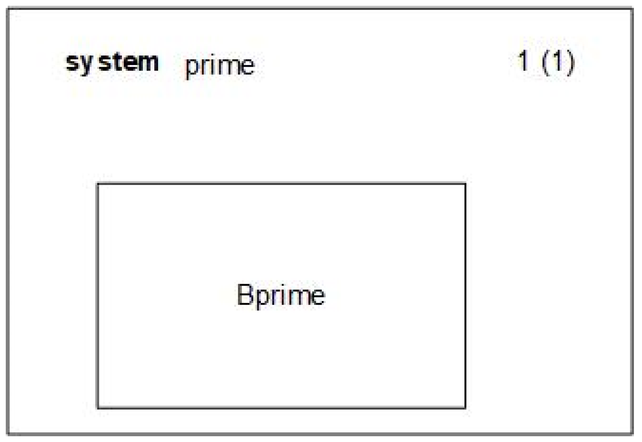
3.2. System Architecture
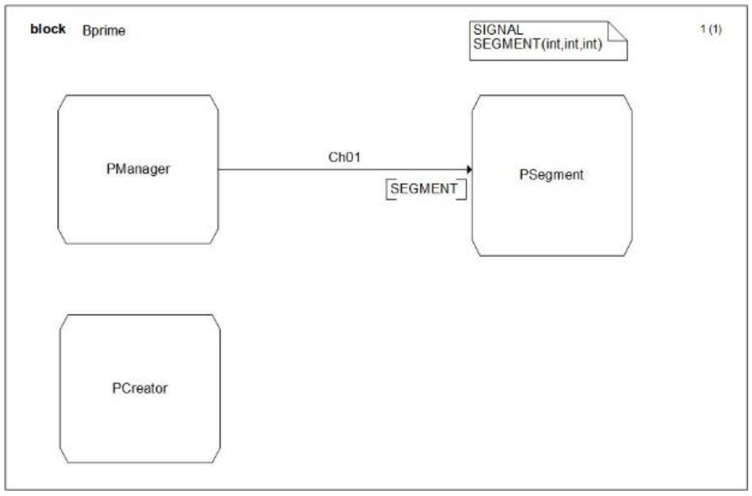
        <sdlblock>
          <block id=“0” name=“Bprime” IP=“” portRead=“” implementation=“” inherits=“”>
             <channels>
                 <channel name=“” start=“PManager” end=“PSegment” dual=“yes”>
                    <event name=“SEGMENT”/>
                 </channel>
             </channels>
            <process id=“1” name=“PSegment” implementation=“model\PSegment.sdlps” IP=“” portRead=“”>
            </process>
            <process id=“2” name=“PManager” implementation=“model\PManager.sdlps” IP=“” portRead=“”>
            </process>
            <DCLS/>
            <procedures/>
            <start/>
          </block>
        </sdlblock>
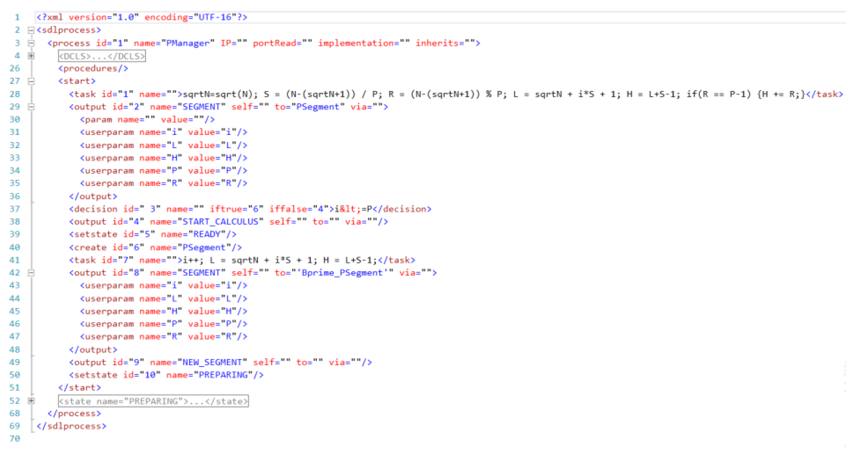
<sdlprocess>
<process id=“3” name=“PSegment” IP=“” portRead=“” implementation=“” inherits=“”>
<DCLS>
<DCL name=“i” type=“int” value=“”/>
<DCL name=“L” type=“int” value=“”/>
...
</DCLS>
<procedures>
<procedure id=“1” name=“ReportList1” implementation=“”>
<params>
<param name=“list” type=“int*” defvalue=“” ref=“yes”/>
...
</params>
<body>
<task id=“1” name=“”>/* Run through each of the numbers in list1 */ for(c = 2; c <= sqrtN; c++) { /* If the number is unmarked */ if(list1[c] == 0) { /* The number is prime, print it */ Report(“%lu “, c); } }</task>
<return id=“2” name=“”/>
</body>
</procedure>
<procedure id=“2” name=“ReportList2” implementation=“”>
<params>
<param name=“list” type=“int*” defvalue=“” ref=“yes”/>
…
</params>
<body>
<task id=“1” name=“”>/* Run through each of the numbers in list2 */ for(c = L; c <= H; c++) { /* If the number is unmarked */ if(list2[c-L] == 0) { /* The number is prime, print it */ Report(“%lu “, c); } }</task>
<return id=“2” name=“”/>
</body>
</procedure>
</procedures>
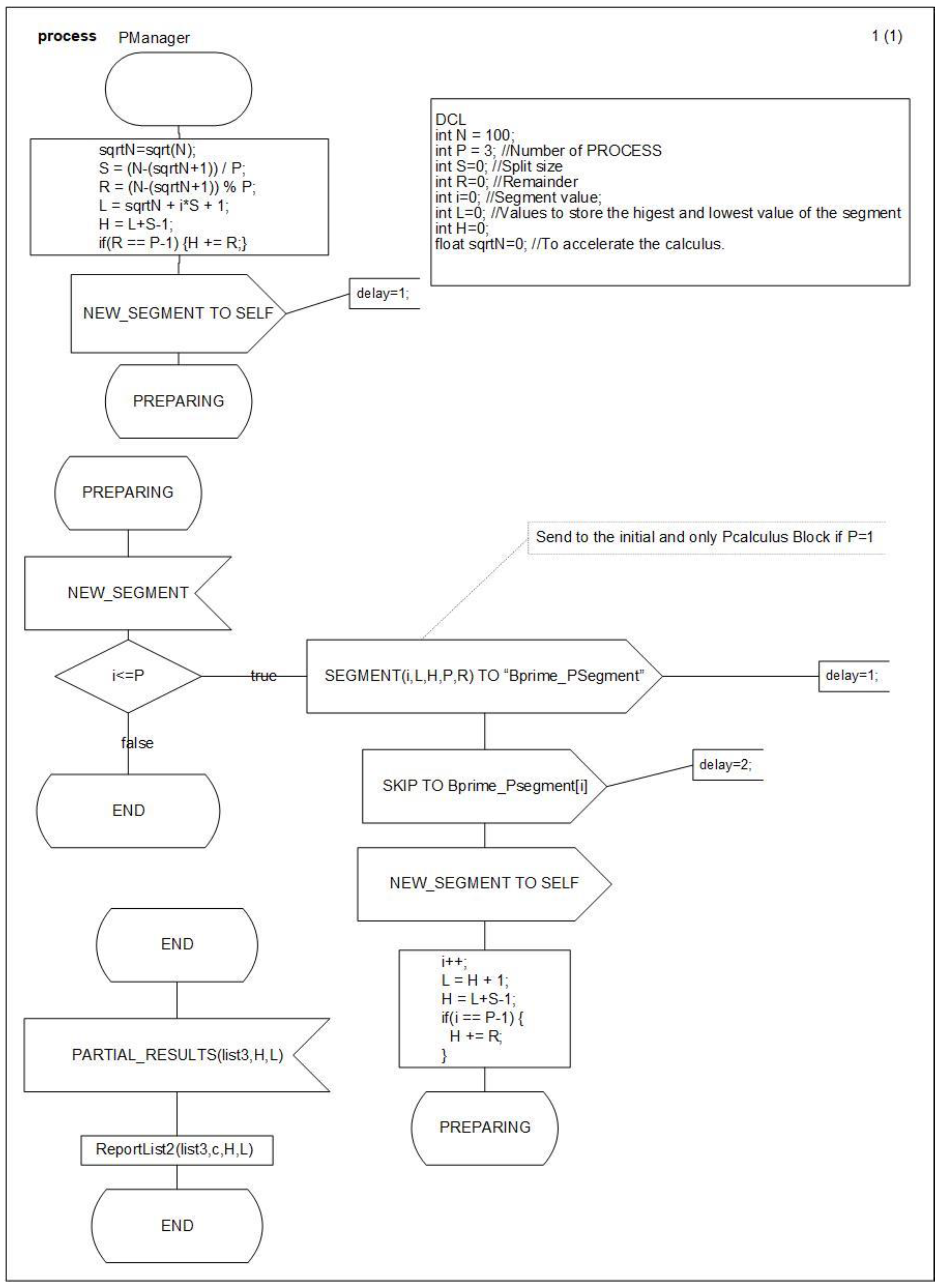
<start>
<task id=“1” name=“”>sqrtN=sqrt(N);</task>
<setstate id=“2” name=“PREPARING”/>
</start>
<state name=“CALCULATING”>
<input id=“1” name=“CALCULUS”/>
...
<setstate id=“6” name=“RESULTS”/>
<output id=“7” name=“PARTIAL_RESULTS” self=“” to=“‘Bprime_PSegment [0]’” via=“”>
<userparam name=“list2” value=“list2”/>
</output>
<setstate id=“8” name=“END”/>
</state>
<state name=“PREPARING”>
3.3. Model-Compiler Libraries
3.4. Simulator
4. Case Studies: Numerical and Agent-Based Models
4.1. Sieve of Eratosthenes SDL Model
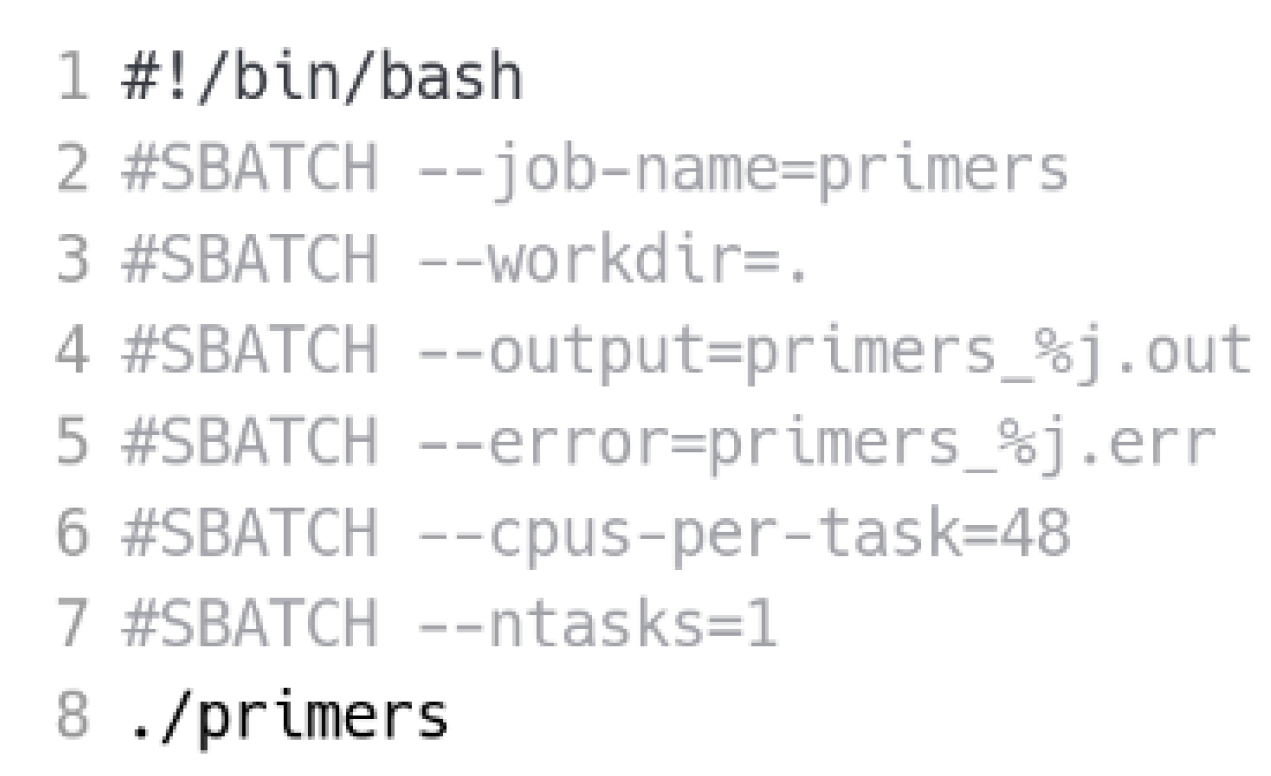
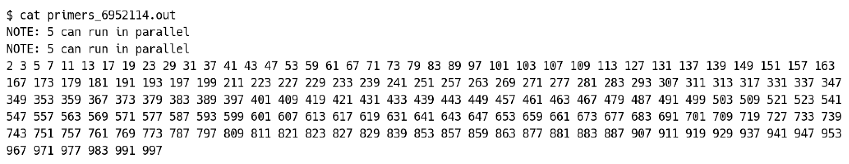
4.2. Sieve of Eratosthenes Parallel Execution
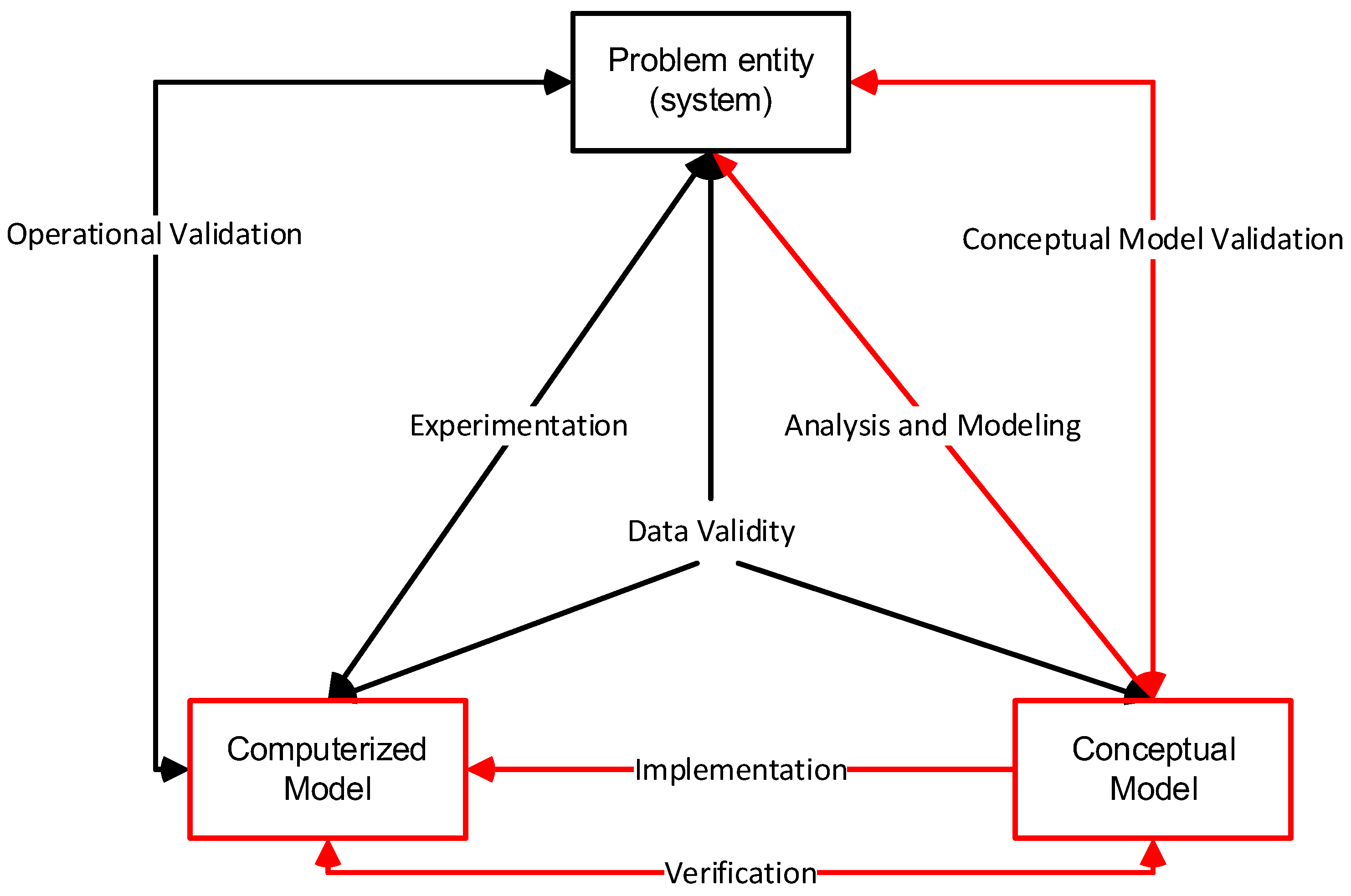
5. Discussion
6. Concluding Remarks
Author Contributions
Funding
Data Availability Statement
Conflicts of Interest
References
- IBM. What Is HPC? Introduction to High-Performance Computing. Available online: https://www.ibm.com/topics/hpc (accessed on 5 November 2023).
- Qian, D. High performance computing: A brief review and prospects. Natl. Sci. Rev. 2016, 3, 16. [Google Scholar] [CrossRef]
- Bak, S.; Bertoni, C.; Boehm, S.; Budiardja, R.; Chapman, B.M.; Doerfert, J.; Eisenbach, M.; Finkel, H.; Hernandez, O.; Huber, J.; et al. OpenMP application experiences: Porting to accelerated nodes. Parallel Comput. 2022, 109, 102856. [Google Scholar] [CrossRef]
- Hoffmann, R.B.; Löff, J.; Griebler, D.; Fernandes, L.G. OpenMP as runtime for providing high-level stream parallelism on multi-cores. J. Supercomput. 2022, 78, 7655–7676. [Google Scholar] [CrossRef]
- Salloum, S.; Dautov, R.; Chen, X.; Peng, P.X.; Huang, J.Z. Big data analytics on Apache Spark. Int. J. Data Sci. Anal. 2016, 1, 145–164. [Google Scholar] [CrossRef]
- Jiang, M.; Gallagher, B.; Chu, A.; Abdulla, G.; Bender, T. Exploiting Spark for HPC Simulation Data: Taming the Ephemeral Data Explosion. In Proceedings of the HPCAsia2020: International Conference on High Performance Computing in Asia-Pacific Region, Fukuoka, Japan, 15–17 January 2020; ACM International Conference Proceeding Series. pp. 150–160. [Google Scholar] [CrossRef]
- Castañé, G.G.; Xiong, H.; Dong, D.; Morrison, J.P. An ontology for heterogeneous resources management interoperability and HPC in the cloud. Future Gener. Comput. Syst. 2018, 88, 373–384. [Google Scholar] [CrossRef]
- Faheem, H.M.; König-Ries, B.; Aslam, M.A.; Aljohani, N.R.; Katib, I. Ontology design for solving computationally-intensive problems on heterogeneous architectures. Sustainability 2018, 10, 441. [Google Scholar] [CrossRef]
- Böhm, S.; Běhálek, M. Usage of Petri Nets for high performance computing. In Proceedings of the FHPC’12—2012 ACM SIGPLAN Functional High Performance Computing, Copenhagen, Denmark, 15 September 2012; pp. 37–47. [Google Scholar] [CrossRef]
- Jensen, K. Coloured Petri Nets; Monographs in Theoretical Computer Science An EATCS Series; Springer: Berlin/Heidelberg, Germany, 1997. [Google Scholar] [CrossRef]
- Liao, C.; Lin, P.-H.; Verma, G.; Vanderbruggen, T.; Emani, M.; Nan, Z.; Shen, X. HPC Ontology: Towards a Unified Ontology for Managing Training Datasets and AI Models for High-Performance Computing. In Proceedings of the 2021 IEEE/ACM Workshop on Machine Learning in High Performance Computing Environments (MLHPC), St. Louis, MO, USA, 15 November 2021; pp. 69–80. [Google Scholar] [CrossRef]
- Sherratt, E. SDL: Meeting the IoT challenge. In System Analysis and Modeling; Lecture Notes in Computer Science; Springer: Cham, Switzerland, 2016; Volume 9959, pp. 36–50. [Google Scholar] [CrossRef]
- Sherratt, E. SDL in a changing world. In System Analysis and Modeling; Lecture Notes in Computer Science; Springer: Cham, Switzerland, 2005; Volume 3319, pp. 96–105. [Google Scholar] [CrossRef]
- Sherratt, E.; Loftus, C. Designing distributed services with SDL. IEEE Concurr. 2000, 8, 59–66. [Google Scholar] [CrossRef]
- Sherratt, E.; Ober, I.; Gaudin, E.; Casas, P.F.I.; Kristoffersen, F. SDL—The IoT Language. In SDL 2015: Model-Driven Engineering for Smart Cities; Lecture Notes in Computer Science; Springer: Berlin/Heidelberg, Germany, 2015; Volume 9369, pp. 27–41. [Google Scholar] [CrossRef]
- Ellsberger, J.; Hogrefe, D.; Sarma, A. SDL: Formal Object-Oriented Language for Communicating Systems, 2nd ed.; Prentice Hall: Upper Saddle River, NJ, USA, 1997. [Google Scholar]
- Meertens, L. Functional Pearl Calculating the Sieve of Eratosthenes. J. Funct. Program. 2004, 14, 759–763. [Google Scholar] [CrossRef]
- Janssen, M.A. Understanding Artificial Anasazi. JASSS 2009, 12, 13. [Google Scholar]
- Trabes, G.G.; Wainer, G.A.; Gil-Costa, V. A Parallel Algorithm to Accelerate DEVS Simulations in Shared Memory Architectures. IEEE Trans. Parallel Distrib. Syst. 2023, 34, 1609–1620. [Google Scholar] [CrossRef]
- Concepcion, A.I.; Zeigler, B.P. DEVS formalism: A framework for hierarchical model development. IEEE Trans. Softw. Eng. 1988, 14, 228–241. [Google Scholar] [CrossRef]
- Zeigler, B.P.; Song, H.S.; Kim, T.G.; Praehofer, H. DEVS framework for modelling, simulation, analysis, and design of hybrid systems. In Hybrid Systems II; Springer: Berlin/Heidelberg, Germany, 1995; pp. 529–551. [Google Scholar] [CrossRef]
- Werner, T.; Päßler, C.; Richter, M.; Kabadshow, I.; Werner, M. A Petri-Net-Based Approach to Modeling Communication Algorithms for HPC Molecular Dynamics Simulations. In Proceedings of the PNSE’23: International Workshop on Petri Nets and Software Engineering, Lisbon, Portugal, 26–27 June 2023; Available online: http://ceur-ws.org (accessed on 31 October 2023).
- Li, Z.; Jiao, L.; Hu, X. Performance analysis for job scheduling in hierarchical HPC systems: A coloured petri nets method. In Algorithms and Architectures for Parallel Processing; Lecture Notes in Computer Science; Springer: Cham, Switzerland, 2015; Volume 9531, pp. 259–280. [Google Scholar] [CrossRef]
- Wang, J. Petri Nets for Dynamic Event-Driven System Modeling. In Handbook of Dynamic System Modeling; Fishwick, P.A., Ed.; Chapman & Hall: Gainesville, FL, USA, 2007; pp. 24-1–24-17. [Google Scholar] [CrossRef]
- Cabasino, M.P.; Giua, A.; Seatzu, C. Introduction to petri nets. In Control of Discrete-Event Systems; Lecture Notes in Control and Information Sciences; Springer: London, UK, 2013; Volume 433, pp. 191–211. [Google Scholar] [CrossRef]
- Doldi, L. SDL Illustrated—Visually Design Executable Models, 1st ed; TMSO Systems: University Park, PA, USA, 2001. [Google Scholar]
- ITU-T. ITU-T-2019—Specification and Description Language—Overview of SDL-2010, ITU-T Recommendation Z.100. 2019. Available online: http://handle.itu.int/11.1002/1000/14048 (accessed on 31 October 2023).
- Casas, P.F.I.; Casas, A.F.I.; Garrido-Soriano, N.; Ortiz, J.; Casanovas, J.; Salom, J. Optimal Buildings’ Energy Consumption Calculus through a Distributed Experiment Execution. Math. Probl. Eng. 2015, 2015, 267974. [Google Scholar] [CrossRef]
- Fonseca Casas, P. Transforming classic Discrete Event System Specification models to Specification and Description Language. Simulation 2015, 91, 249–264. [Google Scholar] [CrossRef]
- Vangheluwe, H.L.M. DEVS as a common denominator for multi-formalism hybrid systems modelling. In Proceedings of the CACSD—IEEE International Symposium on Computer-Aided Control System Design (Cat. No. 00TH8537), Anchorage, AK, USA, 25–27 September 2000. [Google Scholar]
- Zeigler, B.P.; Praehofer, H.; Kim, T.G. Theory of Modeling and Simulation Handbook of Simulator-Based Training Creating Computer Simulation Systems: An Introduction to the High Level Architecture; Prentice Hall: Upper Saddle River, NJ, USA, 2000; Volume 100. [Google Scholar] [CrossRef]
- Doldi, L. Validation of Communications Systems with SDL: The Art of SDL Simulation and Reachability Analysis; Wiley & Sons: Hoboken, NJ, USA, 2003. [Google Scholar]
- PragmaDev SARL. PragmaDev Studio. Available online: http://www.pragmadev.com/product/index.html (accessed on 9 January 2016).
- PragmaDev. Graphical Language to Specify and Design Real Time and Embedded Software September; PragmaDev: Paris, France, 2013. [Google Scholar]
- Cinderella ApS. Cinderella. 2011. Available online: http://www.cinderella.dk/ (accessed on 9 January 2016).
- Rauchwerger, Y.; Kristoffersen, F.; Lahav, Y. Cinderella SLIPPER: An SDL to C-code generator. In SDL 2005: Model Driven; Lecture Notes in Computer Science; Springer: Berlin/Heidelberg, Germany, 2005; Volume 3530, pp. 210–223. [Google Scholar] [CrossRef]
- IBM Co. Rational SDL Suite. Available online: http://www-03.ibm.com/software/products/en/ratisdlsuit (accessed on 9 January 2016).
- Casas, P.F.I.; Palomés, X.P.; Garcia, J.C.; Jové, J. Definition of virtual reality simulation models using specification and description language diagrams. In SDL 2013: Model Driven Dependability Engineering; Springer: Berlin/Heidelberg, Germany, 2013; pp. 258–274. [Google Scholar] [CrossRef]
- Sargent, R.G. Verification validation and accreditation of simulation models. In Proceedings of the 2000 Winter Simulation Conference Proceedings (Cat. No. 00CH37165), Orlando, FL, USA, 10–13 December 2000; pp. 50–59. [Google Scholar]
- Balci, O. Verification, Validation, and Certification of Modeling and Simulation Applications. In Proceedings of the 2003 Winter Simulation Conference, New Orleans, LA, USA, 7–10 December 2003; pp. 150–158. [Google Scholar]
- Casas, P.F.I. A Continuous Process for Validation, Verification, and Accreditation of Simulation Models. Mathematics 2023, 11, 845. [Google Scholar] [CrossRef]
- Sargent, R.G. Verification and validation of simulation models. J. Simul. 2013, 7, 12–24. [Google Scholar] [CrossRef]
- Fonseca, P.; Colls, M.; Casanovas, J. A novel model to predict a slab avalanche configuration using m:n-CAk cellular automata. Comput. Environ. Urban Syst. 2011, 35, 12–24. [Google Scholar] [CrossRef]
- Casas, P.F.I.; Casas, A.F.I. NECADA. Optimization software for sustainable architecture. In Building Simulation Conference; IBPSA: Hyderabad, India, 2015. [Google Scholar]
- IEEE. IEEE Standard for Modeling and Simulation (M&S) High Level Architecture (HLA)—Framework and Rules. Available online: https://standards.ieee.org/ieee/1516/3744/ (accessed on 25 September 2023).
- BSC. Marenostrum. Available online: https://www.bsc.es/es/marenostrum/marenostrum (accessed on 6 June 2019).
- OpenMP. OpenMP. Available online: https://www.openmp.org/ (accessed on 6 June 2019).
- Diamond, J.M. Life with the artificial Anasazi. Nature 2002, 419, 567–568. [Google Scholar] [CrossRef]
- BSC. Running Jobs|BSC Support Knowledge Center. Available online: https://www.bsc.es/supportkc/docs/MareNostrum4/slurm/ (accessed on 25 September 2023).
- Casas, P.F.I.; Subirana, J.G.I.; Carrasco, V.G.I.; Palomes, X.P.I.; Wainer, G. Formal Modeling and Simulation for SARS-CoV-2 Containment Scenarios in Catalonia. Comput. Sci. Eng. 2022, 24, 86–90. [Google Scholar] [CrossRef]
- Reference, T.E.; Input, E. Input Output Reference: The Encyclopedic Reference to EnergyPlus Input and Output, version 8.0; Big Ladder Software: Denver, CO, USA, 2014. [Google Scholar]
- Podnar, I.; Mikac, B.; Caric, A. SDL based approach to software process modeling. In Software Process Technology; Lecture Notes in Computer Science; Springer: Berlin/Heidelberg, Germany, 2000; Volume 1780, pp. 190–202. [Google Scholar] [CrossRef]
- Díaz, M.; Garrido, D.; Troya, J.M. Development of distributed real-time simulators based on CORBA. Simul. Model. Pract. Theory 2007, 15, 716–733. [Google Scholar] [CrossRef]
- Dragomir, I.; Redondo, C.; Jorge, T.; Gouveia, L.; Ober, I.; Kolesnikov, I.; Bozga, M.; Perrotin, M. Model-checking of space systems designed with TASTE/SDL. In Proceedings of the ACM/IEEE 25th International Conference on Model Driven Engineering Languages and Systems, MODELS 2022: Companion Proceedings, Montreal, QC, Canada, 23–28 October 2022; pp. 237–246. [Google Scholar] [CrossRef]
- Borshchev, A.; Karpov, Y.; Kharitonov, V. Distributed simulation of hybrid systems with AnyLogic and HLA. Future Gener. Comput. Syst. 2002, 18, 829–839. [Google Scholar] [CrossRef]


| Name | Symbol | Description |
|---|---|---|
| Start |  | This element allows defining the initial condition for a PROCESS diagram. |
| State |  | The state element contains the name of a state. This element defines the states of behavioral diagrams (like PROCESS diagrams). |
| Input |  | Input elements describe the kind of events that can be received by the process. All branches of a specific state start with an input element since an object changes its state only when a new event is received. |
| Create |  | This element allows the creation of an agent. |
| Task |  | This element enables the interpretation of informal texts or programming code. In this paper, following SDL2010, we use C code. |
| Procedure call |  | These elements perform a procedure call. A PROCEDURE can be defined in the last level of the SDL language. It can be used to encapsulate pieces of the model for its reuse. |
| Output |  | Output elements describe the kind of signals to be sent, the parameters that the signal carries, and the destination. If ambiguity about the signal destination exists, communication can be directed, specifying destinations using a processing identity value (PId), an agent name, or using the sentence via path. If there is more than one path, and no specific output is defined, an arbitrary one is used. The destination value can be stored in a variable for later use. Four PId expressions can be used:
|
| Decision |  | These elements describe bifurcations. Their behavior depends on the answer to the related question. |
Disclaimer/Publisher’s Note: The statements, opinions and data contained in all publications are solely those of the individual author(s) and contributor(s) and not of MDPI and/or the editor(s). MDPI and/or the editor(s) disclaim responsibility for any injury to people or property resulting from any ideas, methods, instructions or products referred to in the content. |
© 2023 by the authors. Licensee MDPI, Basel, Switzerland. This article is an open access article distributed under the terms and conditions of the Creative Commons Attribution (CC BY) license (https://creativecommons.org/licenses/by/4.0/).
Share and Cite
Fonseca i Casas, P.; Romanowska, I.; Garcia i Subirana, J. Specification and Description Language Models Automatic Execution in a High-Performance Environment. Computers 2023, 12, 244. https://doi.org/10.3390/computers12120244
Fonseca i Casas P, Romanowska I, Garcia i Subirana J. Specification and Description Language Models Automatic Execution in a High-Performance Environment. Computers. 2023; 12(12):244. https://doi.org/10.3390/computers12120244
Chicago/Turabian StyleFonseca i Casas, Pau, Iza Romanowska, and Joan Garcia i Subirana. 2023. "Specification and Description Language Models Automatic Execution in a High-Performance Environment" Computers 12, no. 12: 244. https://doi.org/10.3390/computers12120244