
Comparative Analysis of Minimum Chip Thickness, Surface Quality and Burr Formation in Micro-Milling of Wrought and Selective Laser Melted Ti64


Abstract
:1. Introduction
2. Characterization of Ti64 Materials
2.1. Microstructure Analysis of the Fabricated Ti64 Parts
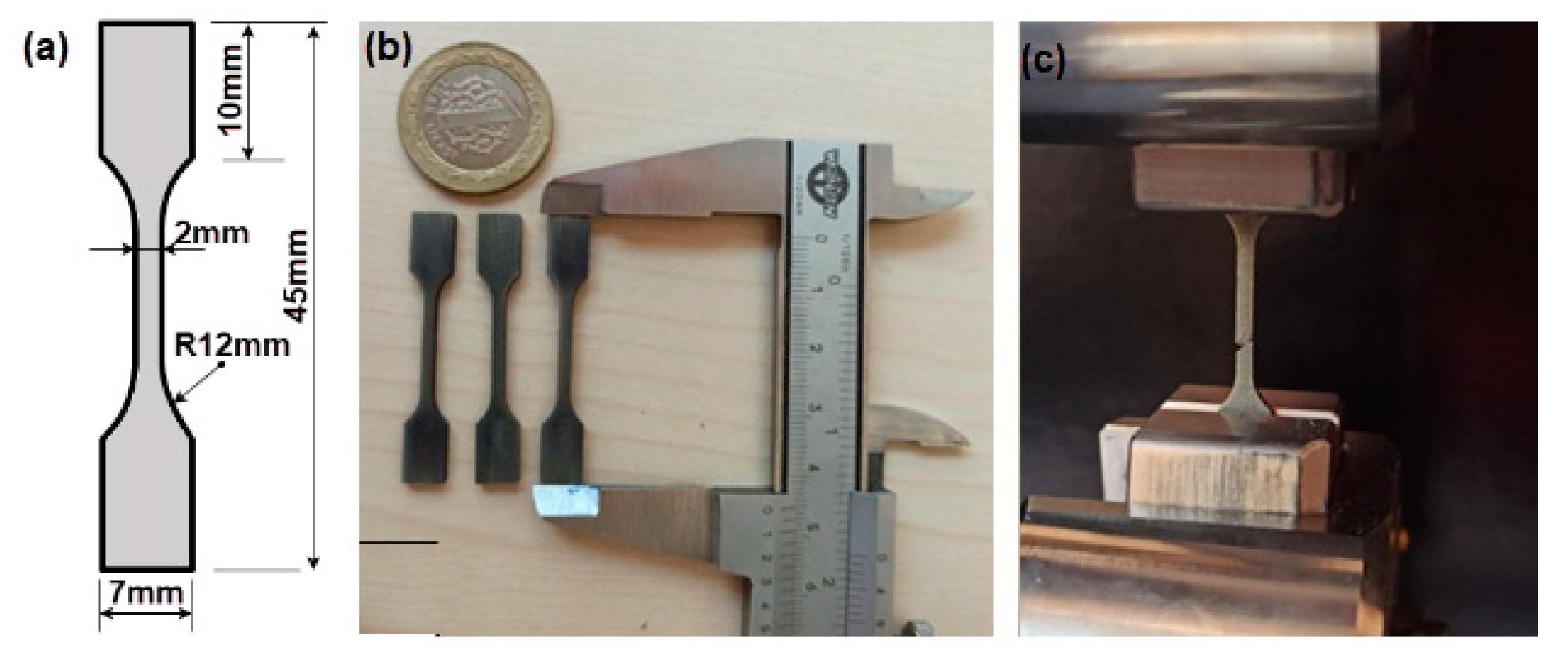
2.2. Hardness Measurement and Tensile Test
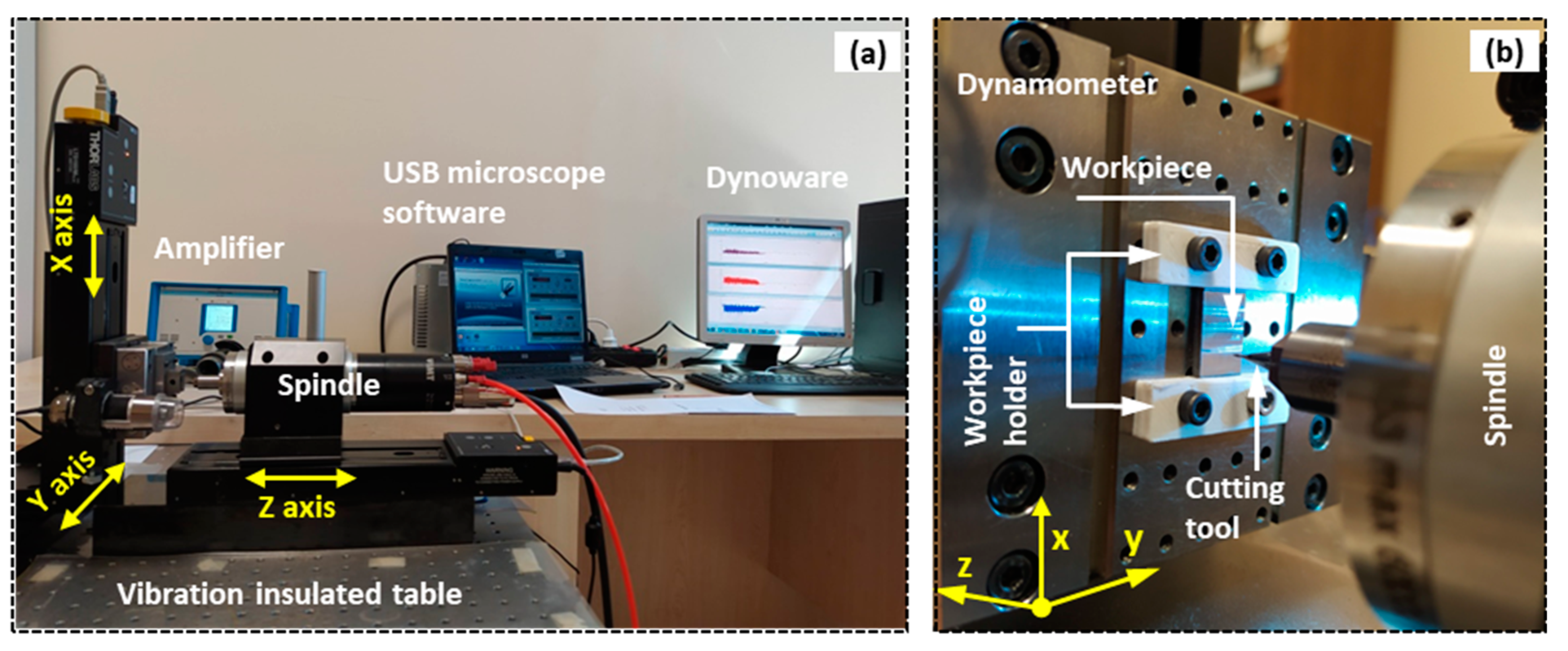
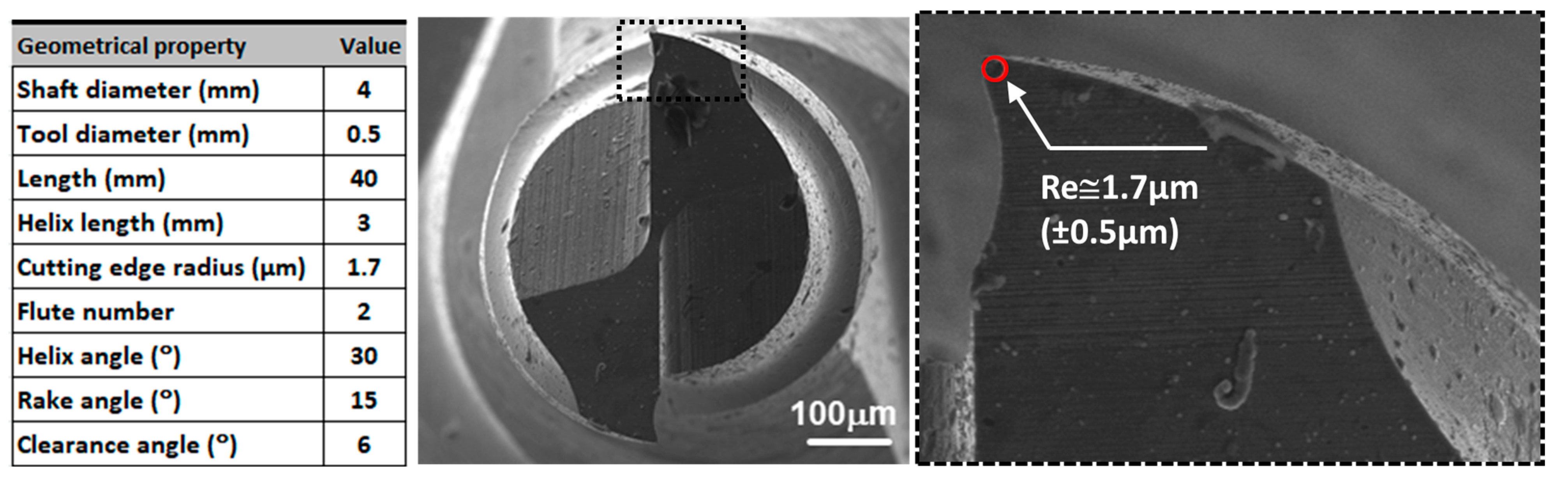
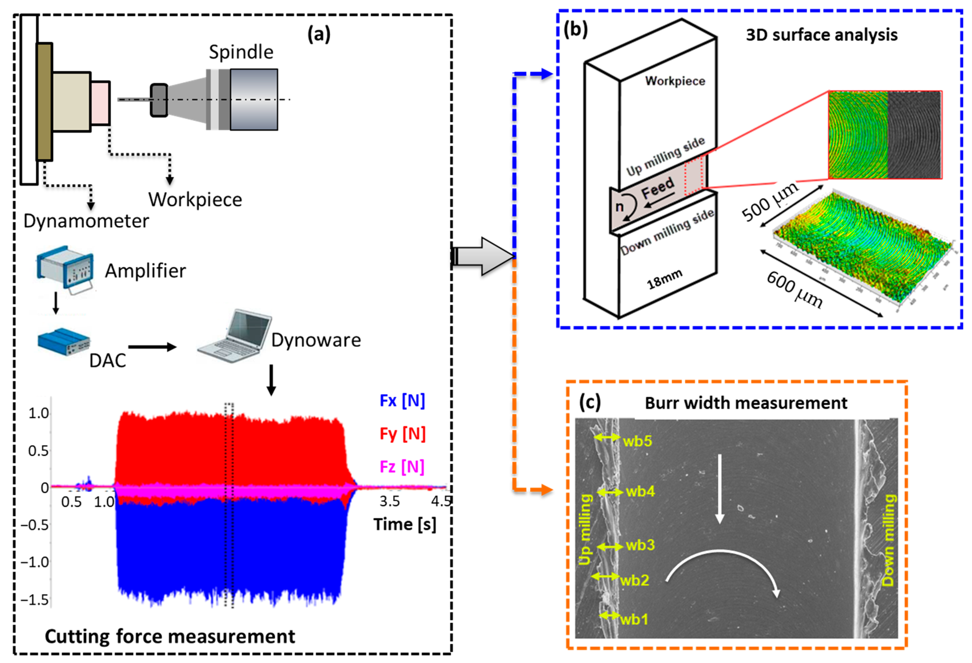
2.3. Micro-Milling Experiments
3. Results and Discussions
3.1. Hardness Measurement and Tensile Test Results
3.2. Cutting Force Results
3.3. Average Areal Surface Roughness Values
3.4. Burr Formation
3.5. Effect of Micro-Milling Parameters on Burr Widths
4. Conclusions
- ⮚
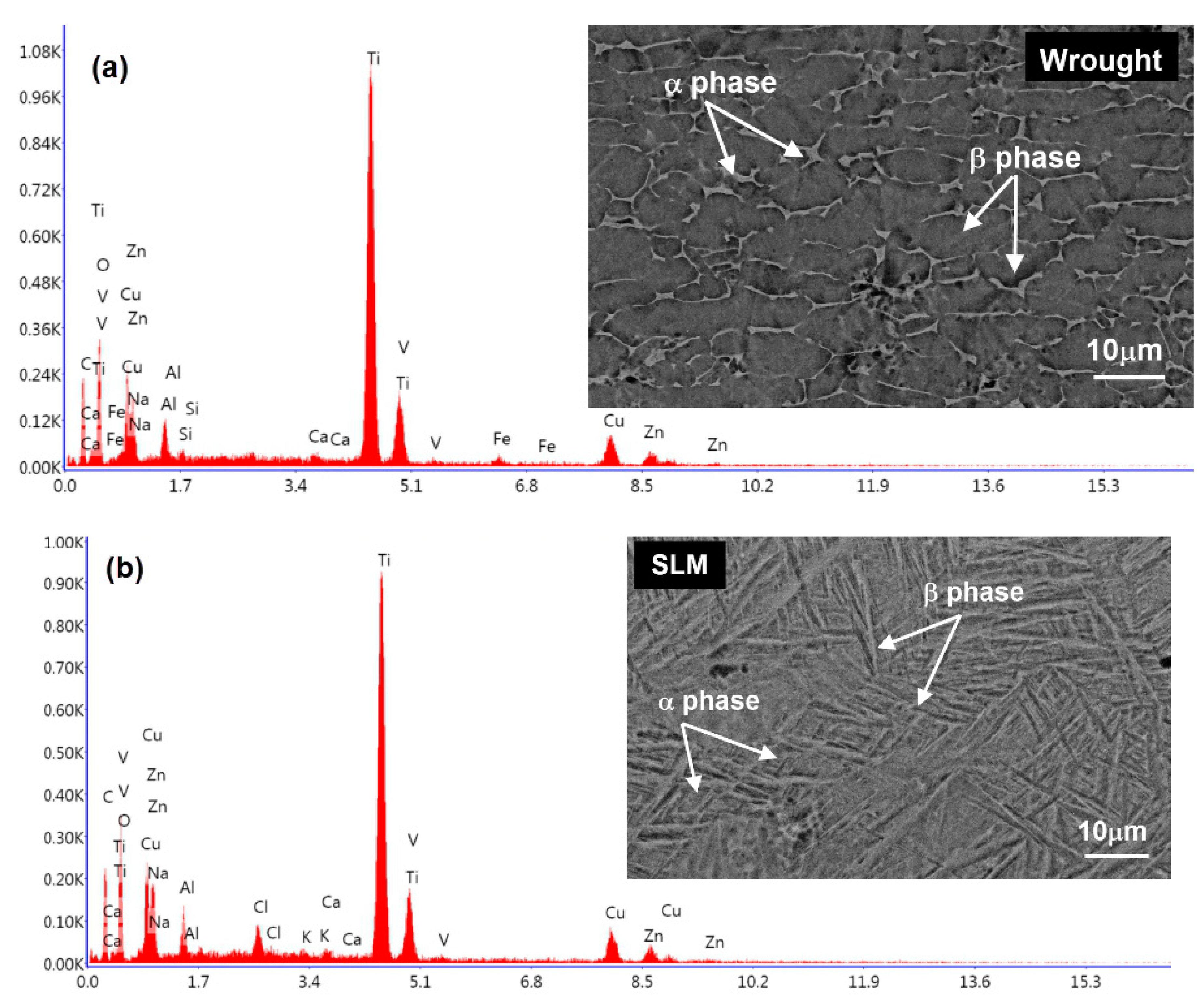
- The microstructures of Ti-6Al-4V (Ti64) parts produced via selective laser melting (SLM) differ from those produced via traditional processes. SLM parts exhibit acicular α martensitic grains, leading to a higher hardness and tensile strength compared to wrought Ti64.
- ⮚
- The micro machinability of SLM Ti64 parts was compared with wrought Ti64 using micro-milling parameters. The minimum chip thickness (MCT) for both SLM and wrought Ti64 was found to be 1 μm/tooth.
- ⮚
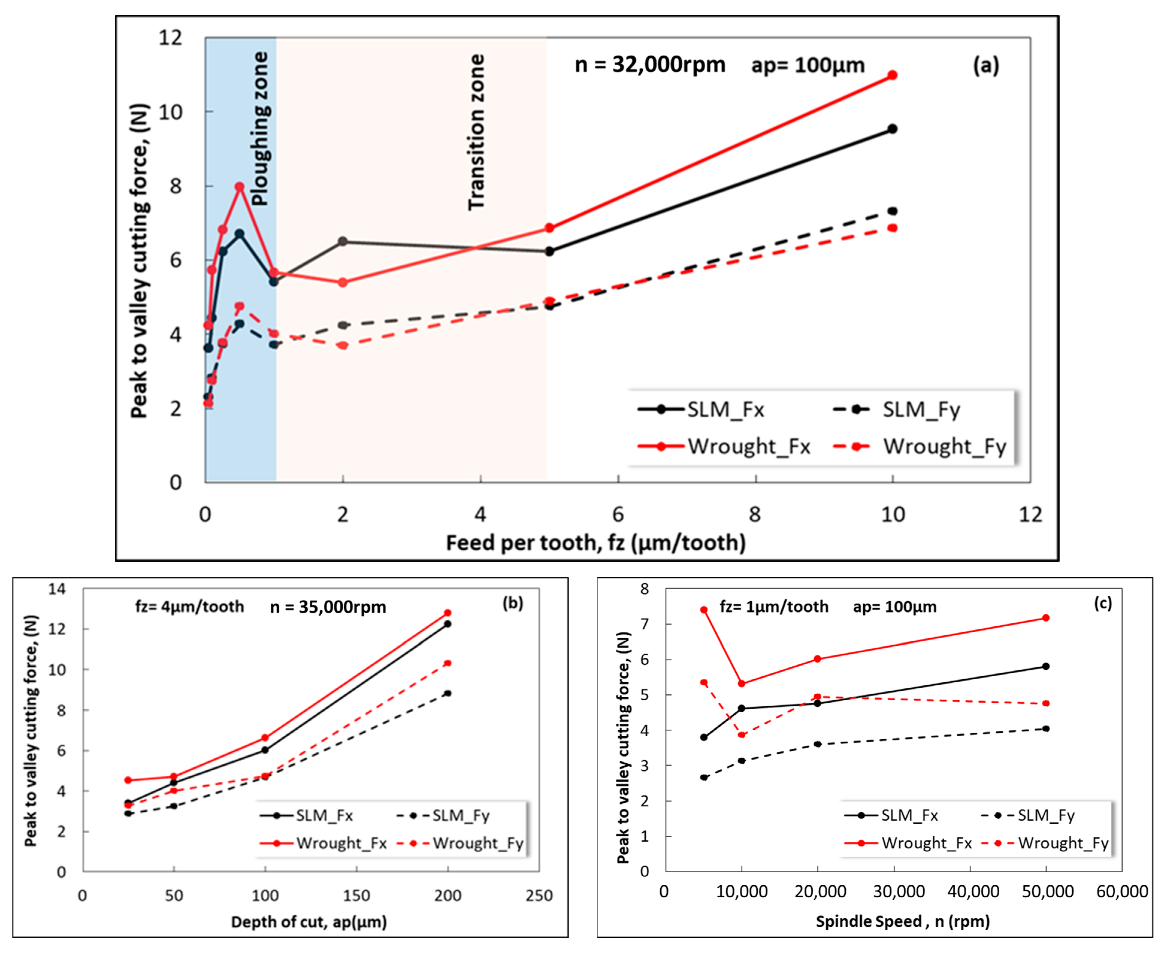
- The cutting forces in micro-milling increased for feed rates smaller than the MCT, indicating a ploughing zone. The cutting forces in the transition zone (1 μm/tooth < fz < 5 μm/tooth) increased and decreased, but the change was not as significant as in the ploughing zone.
- ⮚
- The production technique (SLM or wrought) did not affect the MCT. Both SLM and wrought Ti64 exhibited similar trends in cutting forces with varying feed rates.
- ⮚
- The cutting forces increased linearly with the depth of cut. Wrought Ti64 required higher cutting forces compared to SLM Ti64, indicating that more force is needed to machine the wrought material.
- ⮚
- The influence of the spindle speed on the cutting forces varied for SLM and wrought Ti64. SLM material exhibited lower shear forces despite its higher strength and hardness compared to wrought material.
- ⮚
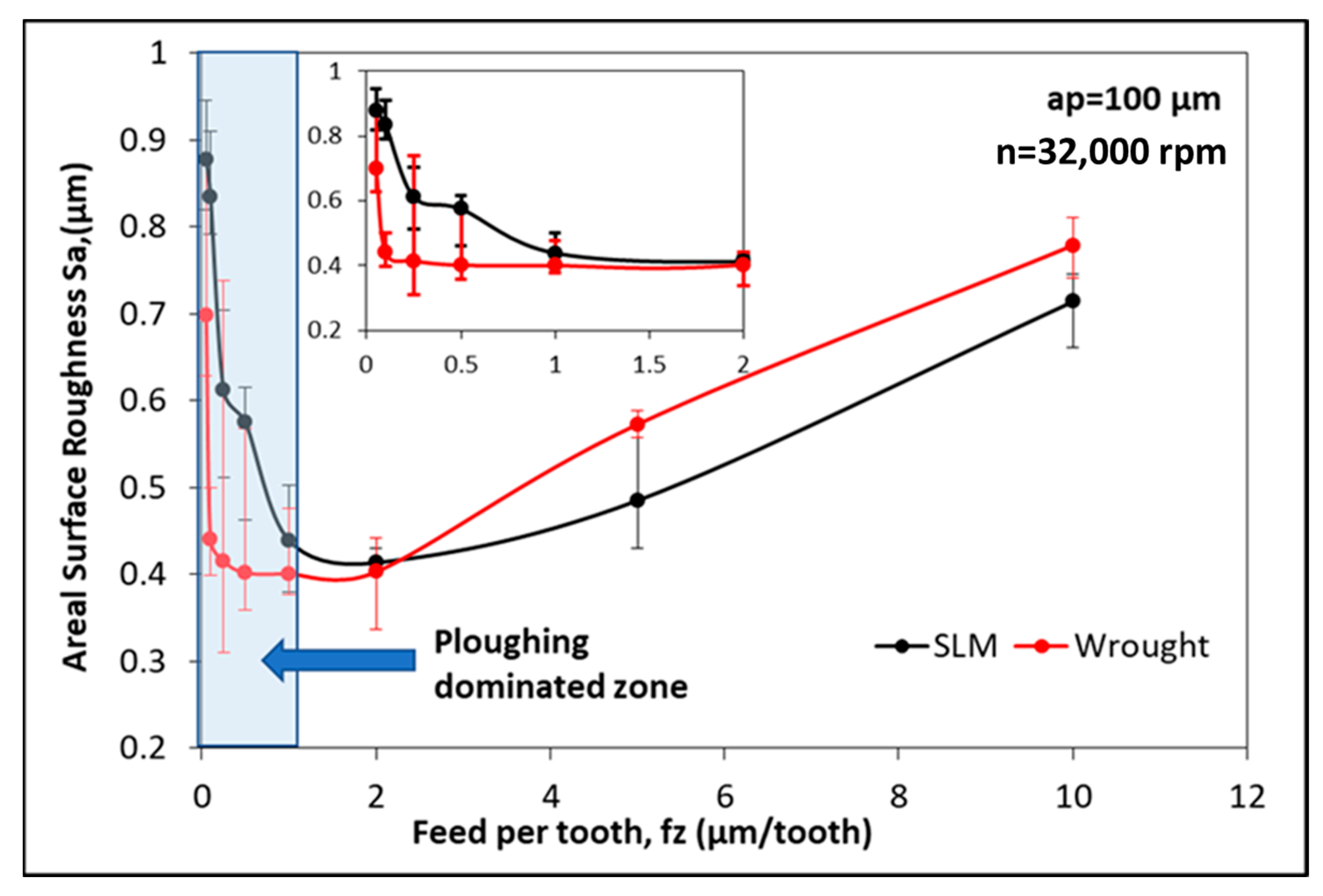
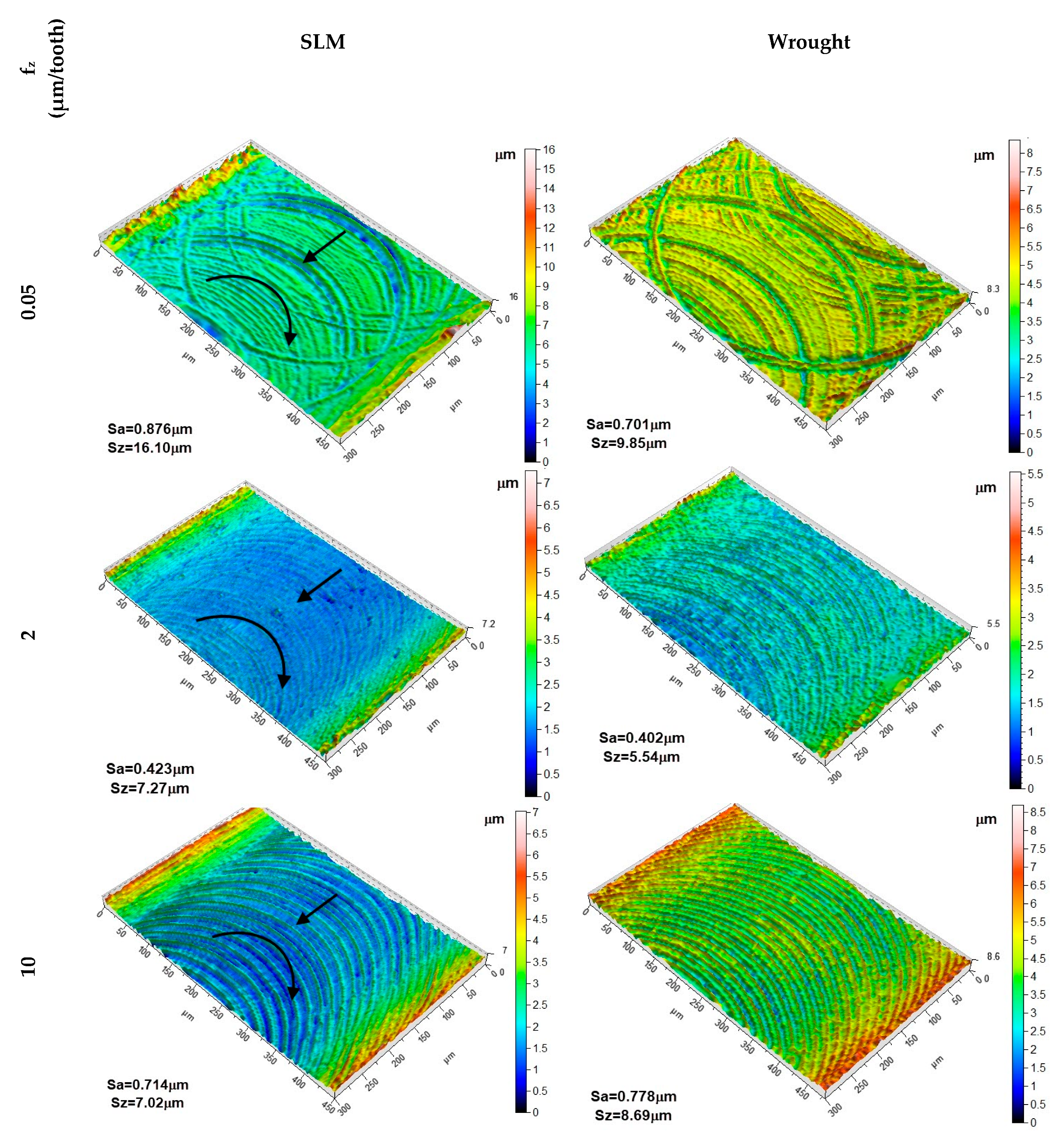
- The surface roughness (Sa) increased for feed rates smaller than 1 μm/tooth, exhibiting a ploughing-dominated zone. For feed rates larger than 2 μm/tooth, SLM Ti64 exhibited lower Sa values compared to wrought Ti64, indicating a better surface quality.
- ⮚
- The grain structure of the SLM material and the presence of fine equiaxed grains contributed to higher surface roughness in the ploughing-dominated zone. Discontinuous chip formation in SLM material also contributed to increased surface roughness.
- ⮚
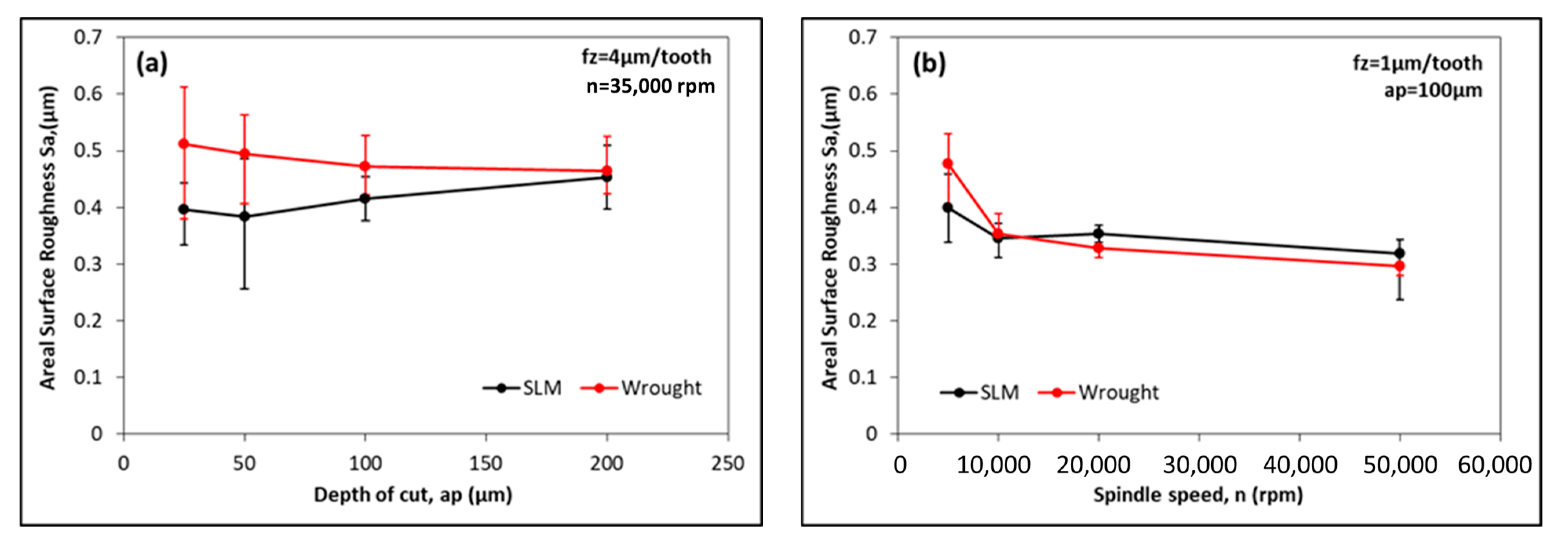
- The variation in surface roughness with the cutting depth and spindle speed showed that the Sa values remained relatively constant with an increasing depth of cut. Lower spindle speeds resulted in higher Sa values due to the increased probability of built-up edge formation.
- ⮚
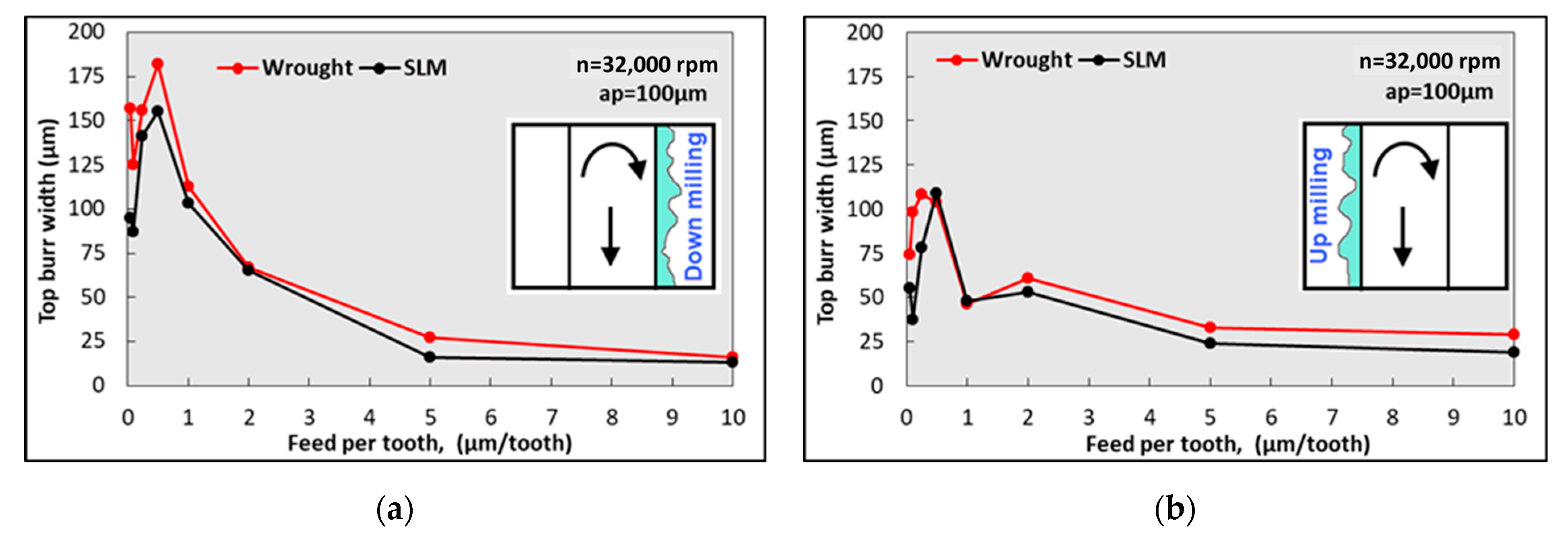
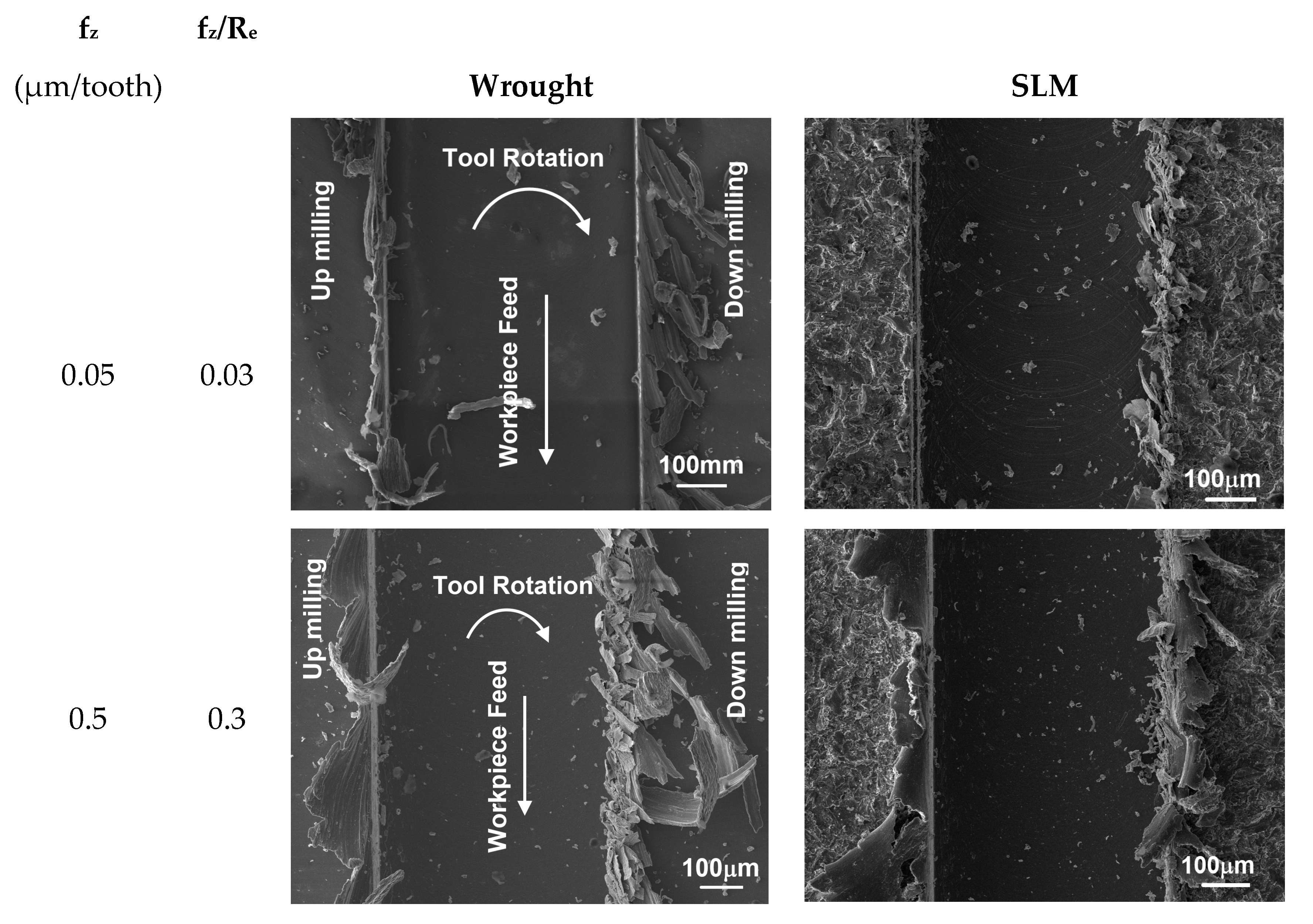
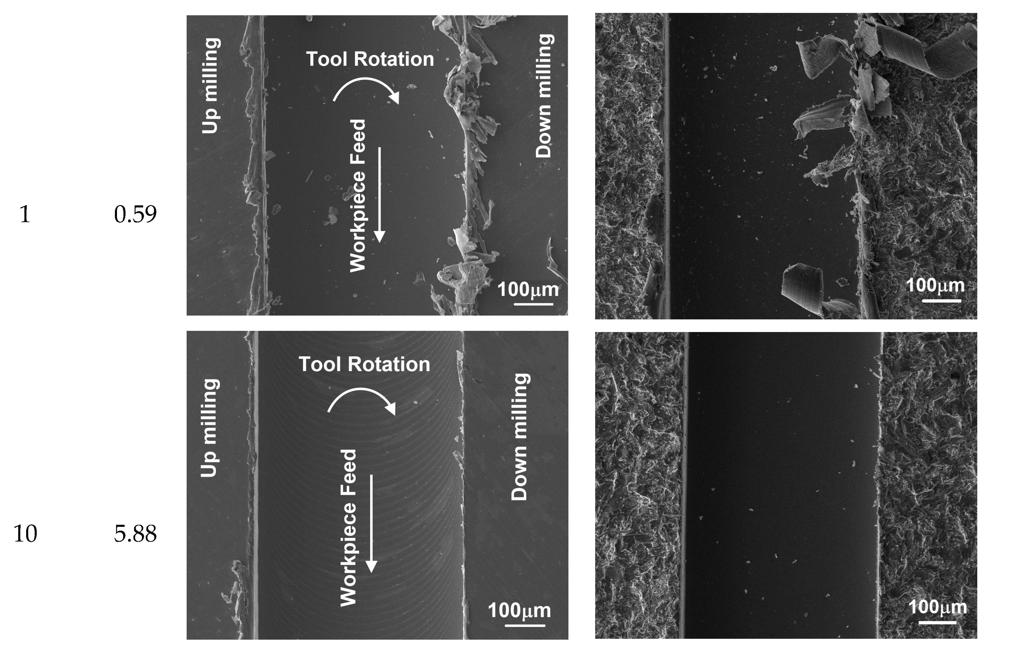
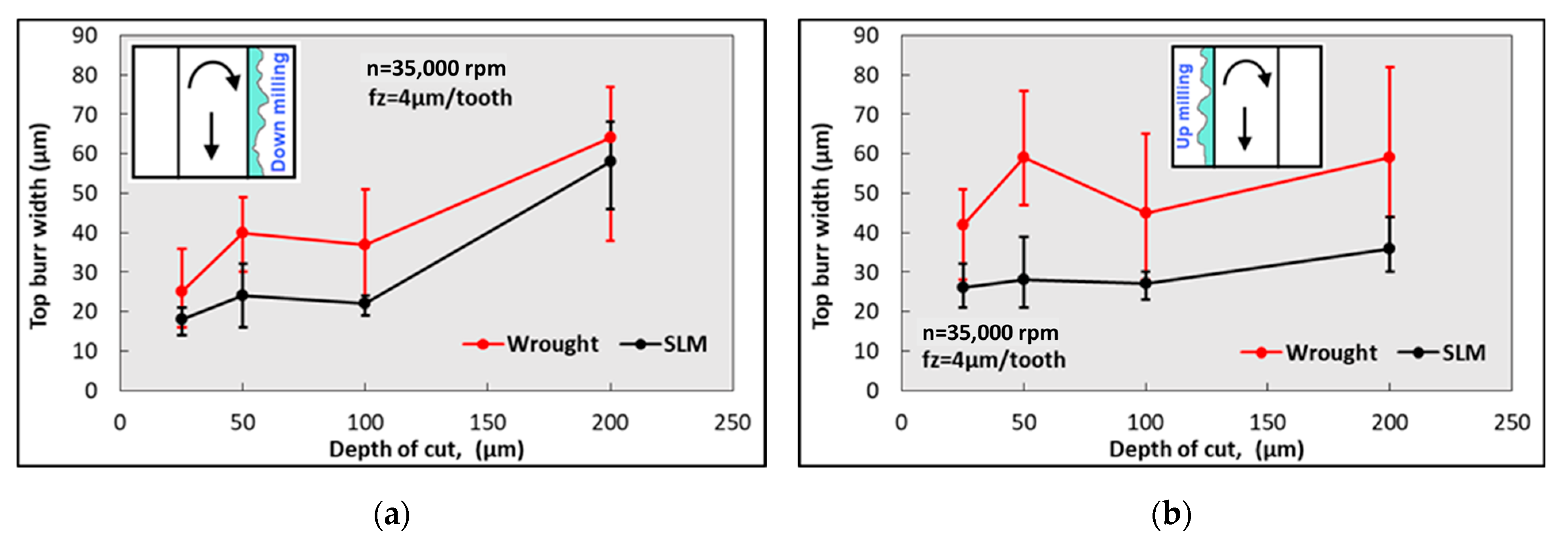
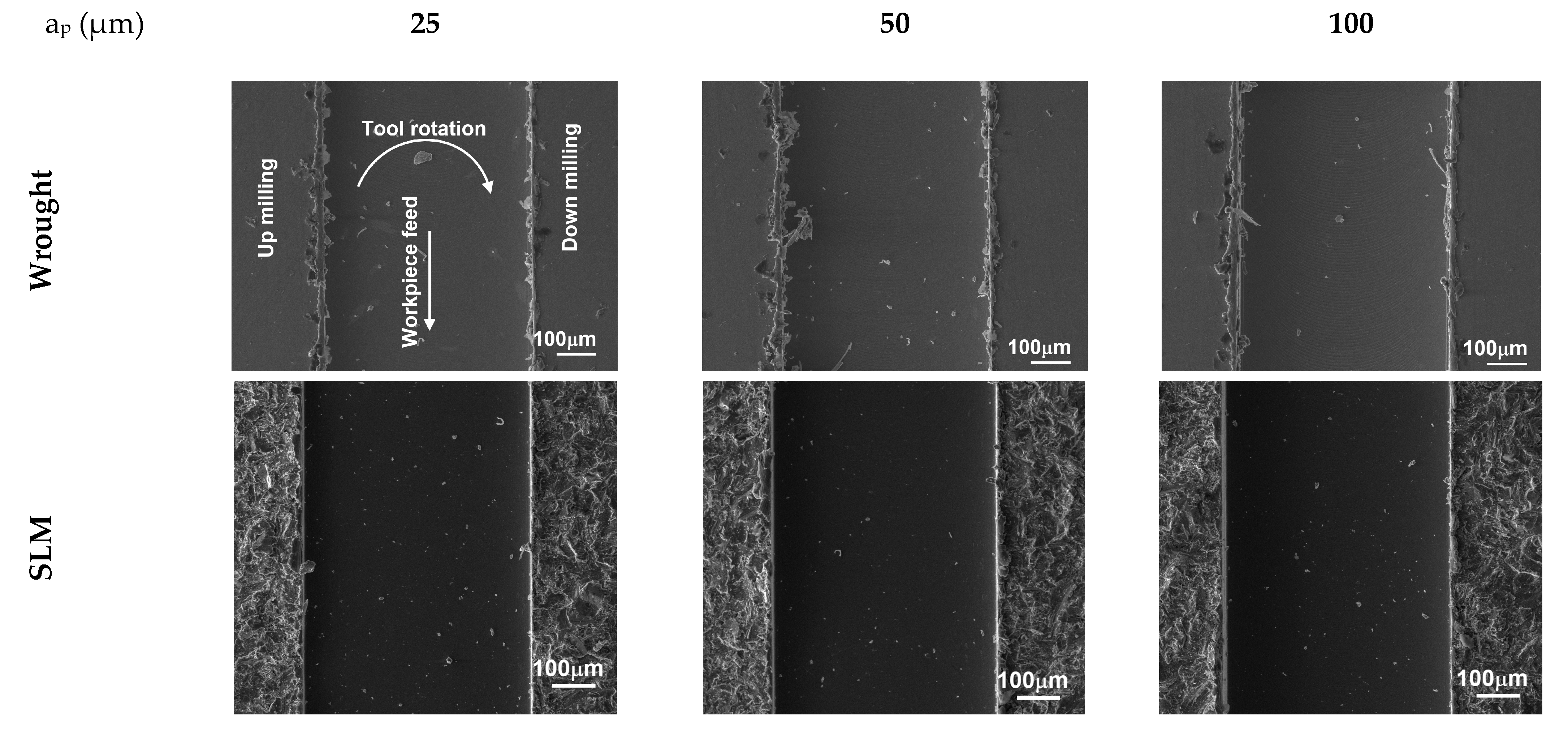
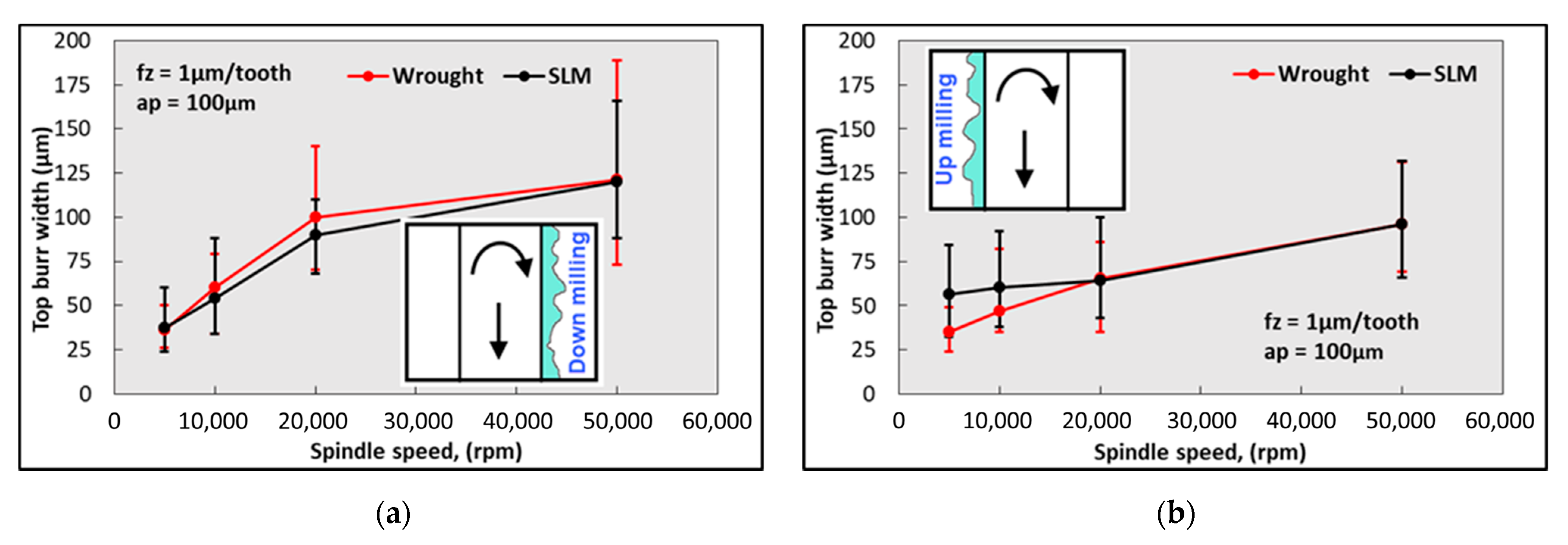
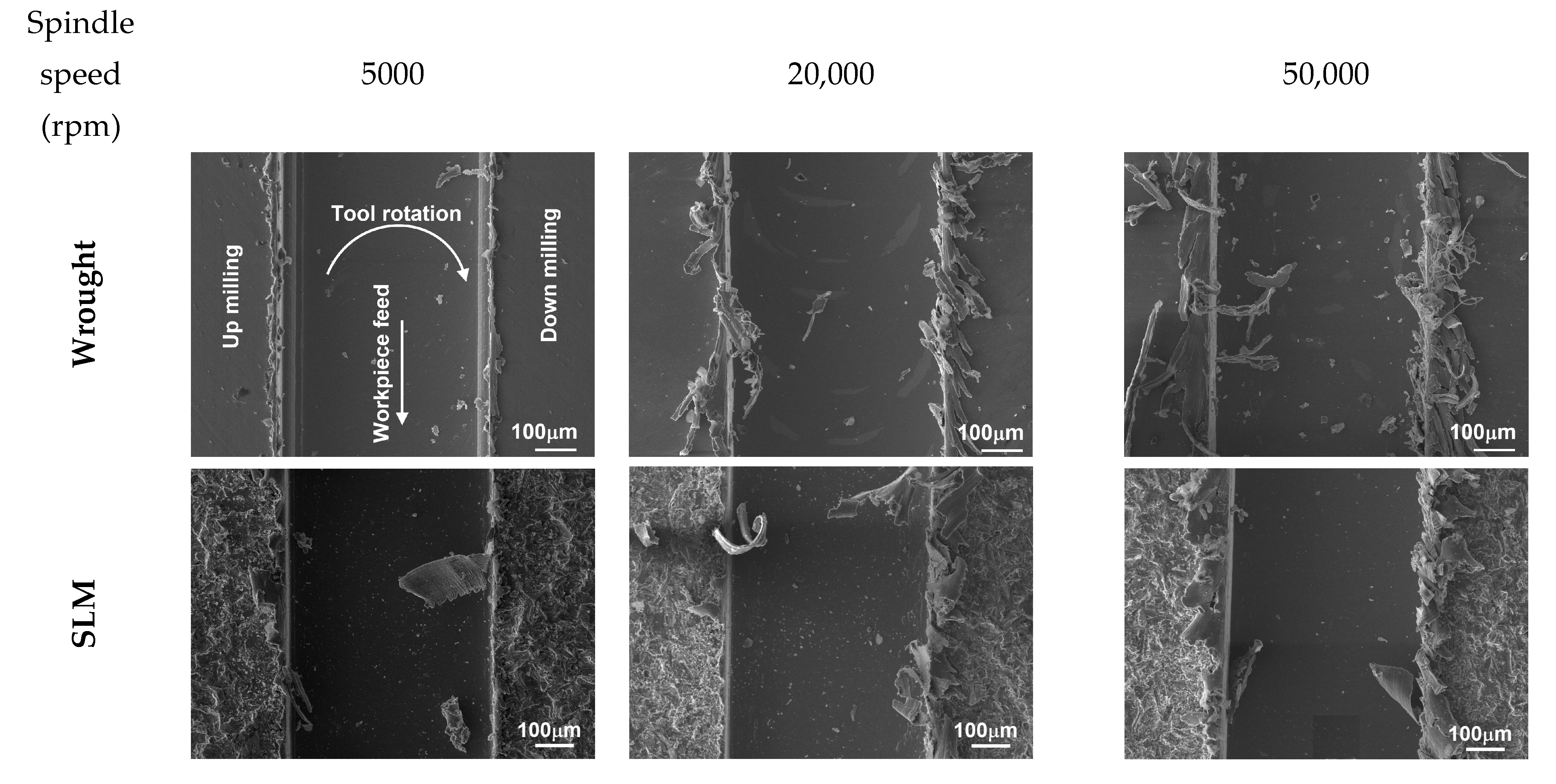
- Burr formation during micro-milling was a complex issue. Optimizing cutting parameters can help to minimize burr formation. The influence of micro-milling parameters on burr widths in SLM and wrought Ti64 was studied.
Author Contributions
Funding
Data Availability Statement
Acknowledgments
Conflicts of Interest
References
- Boban, J.; Ahmed, A. Electric discharge assisted post-processing performance of high strength-to-weight ratio alloys fabricated using metal additive manufacturing. CIRP J. Manuf. Sci. Technol. 2022, 39, 159–174. [Google Scholar] [CrossRef]
- Umbrello, D.; Bordin, A.; Imbrogno, S.; Bruschi, S. 3D finite element modelling of surface modification in dry and cryogenic machining of EBM Ti6Al4V alloy. CIRP J. Manuf. Sci. Technol. 2017, 18, 92–100. [Google Scholar] [CrossRef]
- Ergene, B. Experimental Research on Mechanical Behaviors of Additively Manufactured Cellular Structures from Titanium and Polymer-Based Materials. Ph.D. Thesis, Isparta University of Applied Sciences, Isparta, Turkey, 2020. [Google Scholar]
- Yalçın, B. Investigation for the Basis Properties of the Titanium Alloy Implants Produced with Powder Metallurgy Method. Ph.D. Thesis, Süleyman Demirel University, Isparta, Turkey, 2007. [Google Scholar]
- Parry, L.; Ashcroft, I.A.; Wildman, R.D. Understanding the effect of laser scan strategy on residual stress in selective laser melting through thermo-mechanical simulation. Addit. Manuf. 2016, 12, 1–15. [Google Scholar] [CrossRef]
- Prasad, A.V.S.R.; Ramji, K.; Datta, G.L. An experimental study of wire EDM on Ti-6Al-4V alloy. Proc. Mater. Sci. 2014, 5, 2567–2576. [Google Scholar] [CrossRef]
- Gupta, R.K.; Kumar, V.A.; Mathew, C.; Rao, G.S. Strain hardening of titanium alloy Ti-6Al-4V sheets with prior heat treatment and cold working. Mater. Sci. Eng. A 2016, 662, 537–550. [Google Scholar] [CrossRef]
- Formanoir, C.; Brulard, A.; Vivès, S.; Martin, G.; Prima, F.; Michatte, S.; Riviere, E.; Dolimont, A.; Godet, S. A strategy to improve the work-hardening behavior of Ti-6Al-4V parts produced by additive manufacturing. Mater. Res. Lett. 2017, 5, 201–208. [Google Scholar] [CrossRef]
- Erçetin, A.; Ozgun, O.; Aslantas, K. Powder metal Al2O3 reinforced Mg5Sn matrix composites: Production and characterization. J. Fac. Eng. Archit. Gazi Univ. 2023, 38, 1003–1011. [Google Scholar] [CrossRef]
- Ercetin, A. A novel Mg-Sn-Zn-Al-Mn magnesium alloy with superior corrosion properties. Metall. Res. Technol. 2021, 118, 504. [Google Scholar] [CrossRef]
- Liu, S.; Shin, Y.C. Additive manufacturing of Ti-6Al-4V alloy: A review. Mater. Des. 2019, 164, 107552. [Google Scholar] [CrossRef]
- Huang, R.; Riddle, M.; Graziano, D.; Warren, J.; Das, S.; Nimbalkar, S.; Cresko, J.; Masanet, E. Energy and emissions saving potential of additive manufacturing: The case of lightweight aircraft components. J. Clean. Prod. 2016, 135, 1559–1570. [Google Scholar] [CrossRef]
- ASTM F2792-12; Standard Terminology for Additive Manufacturing Technologies, Standard. American Society for Testing Materials: West Conshohocken Borough, PA, USA, 2012.
- Aggoune, S.; Hamadi, F.; Amara, E.H.; Khelloufi, K.; Tamssaout, T.; Abid, C. Effect of the radiative losses during selective laser melting process. Mater. Today Proc. 2021, 53, 36–41. [Google Scholar] [CrossRef]
- Çevik, Z.A.; Özsoy, K.; Erçetin, A. The Effect of Machining Processes on the Physical and Surface Morphology of Ti6al4v Specimens Produced Through Powder Bed Fusion Additive Manufacturing. Int. J. 3D Print. Technol. Digit. Ind. 2021, 5, 187–194. [Google Scholar] [CrossRef]
- Mukalay, T.A.; Trimble, J.A.; Müvunzi, K.M.; Muvunzi, R. A systematic review of process uncertainty in Ti6Al4V-selective laser melting. CIRP J. Manuf. Sci. Technol. 2022, 36, 185–212. [Google Scholar] [CrossRef]
- Hazlehurst, K.B.; Wang, C.J.; Stanford, M. An investigation into the flexural characteristics of functionally graded cobalt chrome femoral stems manufactured using selective laser melting. Mater. Des. 2014, 60, 177–183. [Google Scholar] [CrossRef]
- Aufa, A.N.; Hassan, M.Z.; Ismail, Z. Recent advances in Ti-6Al-4V additively manufactured by selective laser melting for biomedical implants: Prospect development. J. Alloys Compd. 2021, 896, 163072. [Google Scholar] [CrossRef]
- Ergene, B. Simulation of the production of Inconel 718 and Ti6Al4V biomedical parts with different relative densities by selective laser melting (SLM) method. J. Fac. Eng. Archıt. Gaz. 2022, 37, 469–484. [Google Scholar] [CrossRef]
- Lu, H.Z.; Ma, H.W.; Luo, X.; Wang, Y.; Wang, J.; Lupoi, R.; Yin, S.; Yang, C. Microstructure, shape memory properties, and in vitro biocompatibility of porous NiTi scaffolds fabricated via selective laser melting. J. Mater. Res. Technol. 2021, 15, 6797–6812. [Google Scholar] [CrossRef]
- Lee, W.; Jeong, Y.; Yoo, J.; Huh, H.; Park, S.J.; Park, S.H.; Yoon, J. Effect of auxetic structures on crash behavior of cylindrical tube. Compos. Struct. 2019, 208, 836–846. [Google Scholar] [CrossRef]
- Seabra, M.; Azevedo, J.; Araújo, A.; Reis, L.; Pinto, E.; Alves, N.; Santos, R.; Mortágua, J.P. Selective laser melting (SLM) and topology optimization for lighter aerospace componentes. Procedia. Struct. Integr. 2016, 1, 289–296. [Google Scholar] [CrossRef]
- Mohanavel, V.; Ashraff, A.K.S.; Ranganathan, K.; Jeffrey, J.A.; Ravikumar, A.A.; Rajkumar, S. The roles and applications of additive manufacturing in the aerospace and automobile sector. Mater. Today Proc. 2021, 47, 405–409. [Google Scholar] [CrossRef]
- Sun, Q.; Sun, J.; Guo, K.; Wang, L. Compressive mechanical properties and energy absorption characteristics of SLM fabricated Ti6Al4V triply periodic minimal surface cellular structures. Mech. Mater. 2022, 166, 104241. [Google Scholar] [CrossRef]
- Yang, X.; Li, Y.; Duan, M.; Jiang, W.; Chen, D.; Li, B. An investigation of ductile fracture behavior of Ti6Al4V alloy fabricated by selective laser melting. J. Alloys Compd. 2022, 890, 161926. [Google Scholar] [CrossRef]
- Kurdi, A.; Basak, A.K. Micro-mechanical behaviour of selective laser melted Ti6Al4V under compression. Mater. Sci. Eng. A 2021, 826, 141975. [Google Scholar] [CrossRef]
- Palmeri, D.; Bufa; Pollara, G.; Fratini, L. Sample building orientation effect on porosity and mechanical properties in selective laser melting of Ti6Al4V titanium alloy. Mater. Sci. Eng. A 2022, 830, 142306. [Google Scholar] [CrossRef]
- Liang, X.; Du, P.; Li, S.; Zhang, C. Tribological properties of additive manufactured Ti6Al4V against cemented carbide under dry sliding conditions. Tribol. Int. 2022, 167, 107358. [Google Scholar] [CrossRef]
- Polishetty, A.; Shunmugavel, M.; Goldberg, M.; Littlefair, G.; Singh, R.K. Cutting force and surface finish analysis of machining additive manufactured titanium alloy Ti6Al4V. Procedia Manuf. 2017, 7, 284–289. [Google Scholar] [CrossRef]
- Bonaiti, G.; Parenti, P.; Annoni, M.; Kapoor, S. Micro-milling machinability of DED additive titanium Ti-6Al-4V. Procedia Manuf. 2017, 10, 497–509. [Google Scholar] [CrossRef]
- Hojati, F.; Daneshi, A.; Soltani, B.; Azarhoushang, B.; Biermann, D. Study on machinability of additively manufactured and conventional titanium alloys in micro-milling process. Precis. Eng. 2020, 62, 1–9. [Google Scholar] [CrossRef]
- Coz, G.L.; Fischer, M.; Piquard, R.; D’Acunto, A.; Laheurte, P.; Dudzinski, D. Micro cutting of Ti-6Al-4V parts produced by SLM process. Procedia CIRP 2017, 58, 228–232. [Google Scholar] [CrossRef]
- Khaliq, W.; Zhang, C.; Jamil, M.; Khan, A.M. Tool wear, surface quality, and residual stresses analysis of micro-machined additive manufactured Ti6Al4V under dry and MQL conditions. Tribol Int. 2020, 151, 106408. [Google Scholar] [CrossRef]
- Campos, F.O.; Araujo, A.C.; Munhoz, A.L.J.; Kapoor, S.G. The influence of additive manufacturing on the micromilling machinability of Ti6Al4V: A comparison of SLM and commercial workpieces. J. Manuf. Process. 2020, 60, 299–307. [Google Scholar] [CrossRef]
- Uçak, N.; Çiçek, A.; Aslantas, K. Machinability of 3D printed metallic materials fabricated by selective laser melting and electron beam melting: A review. J. Manuf. Process. 2022, 80, 414–457. [Google Scholar] [CrossRef]
- Motyka, M.; Kubiak, K.; Sieniawski, J.; Ziaja, W. Hot plasticity of alpha beta alloys. Titanium alloys–towards achieving enhanced properties for diversified applications. Rijeka InTech 2012, 10, 34806. [Google Scholar] [CrossRef]
- ASTM E92-17; Standard Test Methods for Vickers Hardness and Knoop Hardness of Metallic Materials. American Society for Testing Materials: West Conshohocken Borough, PA, USA, 2009.
- Bolat, C.; Ergene, B.; Karakilinc, U.; Goksenli, A. Investigating on the machinability assessment of precision machining pumice reinforced AA7075 syntactic foam. Proc. Inst. Mech. Eng. Part C 2022, 236, 2380–2394. [Google Scholar] [CrossRef]
- Thijs, L.; Verhaeghe, F.; Craeghs, T.; Humbeeck, J.V.; Kruth, J.P. A study of the microstructural evolution during selective laser melting of Ti–6Al–4V. Acta Mater. 2010, 58, 3303–3312. [Google Scholar] [CrossRef]
- Sercombe, T.; Jones, N.; Day, R.E.; Kop, A. Heat treatment of Ti-6Al-7Nb components produced by selective laser melting. Rapid Prototyp. J. 2008, 14, 300–304. [Google Scholar] [CrossRef]
- Simonelli, M.; Tse, Y.Y.; Tuck, C. Effect of the build orientation on the mechanical properties and fracture modes of SLM Ti–6Al–4V. Mater. Sci. Eng. A 2014, 616, 1–11. [Google Scholar] [CrossRef]
- Costa, A.; Miranda, R.; Quintino, L.; Yapp, D. Analysis of beam material interaction in wel-ding of titanium with fiber lasers. Mater. Ma-Nufacturing Process. 2007, 22, 798–803. [Google Scholar] [CrossRef]
- Chae, J.; Park, S.; Freiheit, T. Investigation of micro-cutting operations. Int. J. Mach. Tools Manuf. 2006, 46, 313–332. [Google Scholar] [CrossRef]
- Ucun, I.; Aslantaş, K.; Bedir, F. The effect of minimum quantity lubrication and cryogenic pre-cooling on cutting performance in the micro milling of inconel 718. Proc. Inst. Mech. Eng. Part B 2015, 229, 2134–2143. [Google Scholar] [CrossRef]
- Alatrushı, L.K.H. The Investigation of Machinability of Titanium-Based Alloys (Ti6Al4V, Ti5553) in Micro Conditions. Ph.D. Thesis, Süleyman Demirel University, Isparta, Turkey, 2018. [Google Scholar]
- Ucun, I.; Aslantaş, K.; Bedir, F. The performance of DLC-coated and uncoated ultra-fine carbide tools in micromilling of inconel 718. Precis. Eng. 2015, 41, 135–144. [Google Scholar] [CrossRef]
- Wang, J.J.J.; Zheng, M.Y. On the machining characteristics of H13 tool steel in different hardness states in ball end milling. J. Adv. Manuf. Technol. 2003, 22, 855–863. [Google Scholar] [CrossRef]
- Edwards; Ramulu, M. Effect of build direction on the fracture toughness and fatigue crack growth in selective laser melted Ti-6Al-4V. Fatigue Fract. Eng. Mater. Struct. 2015, 38, 1228–1236. [Google Scholar] [CrossRef]
- Airao, J.; Chandrakant, H.K.; Nirala, C.K. Measurement and analysis of tool wear and surface characteristics in micro turning of SLM Ti6Al4V and wrought Ti6Al4V. Measurement 2023, 226, 112281. [Google Scholar] [CrossRef]
- Aslantas, K.; Alatrushi, L.K.H.; Yılmaz, N.; Bedir, F.; Kaynak, Y. An experimental analysis of minimum chip thickness in micro-milling of two different titanium alloys. Proc. Inst. Mech. Eng. B J. Eng. 2020, 204, 12. [Google Scholar] [CrossRef]
- Oliaei, S.N.B.; Karpat, Y. Built-up edge effects on process outputs of titanium alloy micro milling. Precis Eng. 2017, 49, 305–315. [Google Scholar] [CrossRef]
- Filiz, S.; Conley, C.M.; Wasserman, M.B.; Ozdoganlar, O.B. An experimental ınvestigation of micro-machinability of copper 101 using tungsten carbide micro-end mills. Int. J. Mach. Tools Manuf. 2007, 47, 1088–1100. [Google Scholar] [CrossRef]
- Lee, K.; Stirn, B.; Dornfeld, D.A. Burr Formation in Micro-Machining Aluminum, 6061-T6; ICPE: Berlin, Germany, 2002; pp. 47–51. [Google Scholar] [CrossRef]
- Schmidt, J.; Tritschler, H. Micro cutting of steel. Microsyst. Technol. 2004, 10, 167–174. [Google Scholar] [CrossRef]
- Litwinski, K.M.; Min, S.; Lee, D.E.; Dornfeld, D.A.; Lee, N. Scalability of tool path planning to micro machining. In Proceedings of the 1st International Conference on Micromanufacturing (ICOMM), University of Illinois, Urbana-Champaign, Champaign, IL, USA, 13–15 September 2006. [Google Scholar]
- Kou, Z.; Wan, Y.; Cai, Y.; Liang, X.; Liu, Z. Burr Controlling in Micro Milling with Supporting Material Method. Procedia Manuf. 2015, 1, 501–511. [Google Scholar] [CrossRef]
- Chen, L.; Deng, D.; Pi, G.; Huang, X.; Zhou, W. Burr formation and surface roughness characteristics in micro-milling of microchannels. Int. J. Adv. Manuf. Technol. 2020, 111, 1277–1290. [Google Scholar] [CrossRef]
- Akkoyun, F.; Ercetin, A.; Aslantas, K.; Pimenov, D.Y.; Giasin, K.; Lakshmikanthan, A.; Aamir, M. Measurement of micro burr and slot widths through image processing: Comparison of manual and automated measurements in micro-milling. Sensors 2021, 21, 4432. [Google Scholar] [CrossRef] [PubMed]
- Aslantas, K.; Hascelik, A.; Çiçek, A. Performance evaluation of DLC and NCD coatings in micro-milling of Al7075-T6 alloy. J. Manuf. Process. 2022, 81, 976–990. [Google Scholar] [CrossRef]
- Chen, M.J.; Ni, H.B.; Wang, Z.J.; Jiang, Y. Research on the modeling of burr formation process in micro-ball end milling operation on Ti–6Al–4V. Int. J. Adv. Manuf. Technol. 2012, 62, 901–912. [Google Scholar] [CrossRef]
- Yang, K.; Bai, Q.S.; Yu, F.L.; Liang, Y.C. Modelling and experimental analysis of the mechanism of micro-burr formation in microend-milling process. Nano Precis. Eng. 2010, 8, 75–83. [Google Scholar] [CrossRef]
- Özel, T.; Thepsonthi, T.; Ulutan, D.; Kaftanoğlu, B. Experiments and finite element simulations on micro-milling of Ti-6Al-4V alloy with uncoated and CBN coated micro-tools. CIRP Ann. 2011, 60, 185–188. [Google Scholar] [CrossRef]
- Aslantas, K.; Ekici, E.; Çiçek, A. Optimization of process parameters for micro milling of Ti-6Al-4V alloy using Taguchi-based gray relational analysis. Measurement 2018, 128, 419–427. [Google Scholar] [CrossRef]
- Wu, X.; Du, M.; Shen, J.; Jiang, F.; Li, Y.; Liu, L. Experimental research on the top burr formation in micro milling. Int. J. Adv. Manuf. 2021, 117, 3477–3486. [Google Scholar] [CrossRef]


| Chemical Composition | Ti | Al (%) | V (%) | O | N | C | H | Fe |
|---|---|---|---|---|---|---|---|---|
| Main Element | 5.5–6.75 | 3.5–4.5 | <2000 ppm | <500 ppm | <800 ppm | <150 ppm | <3000 ppm | |
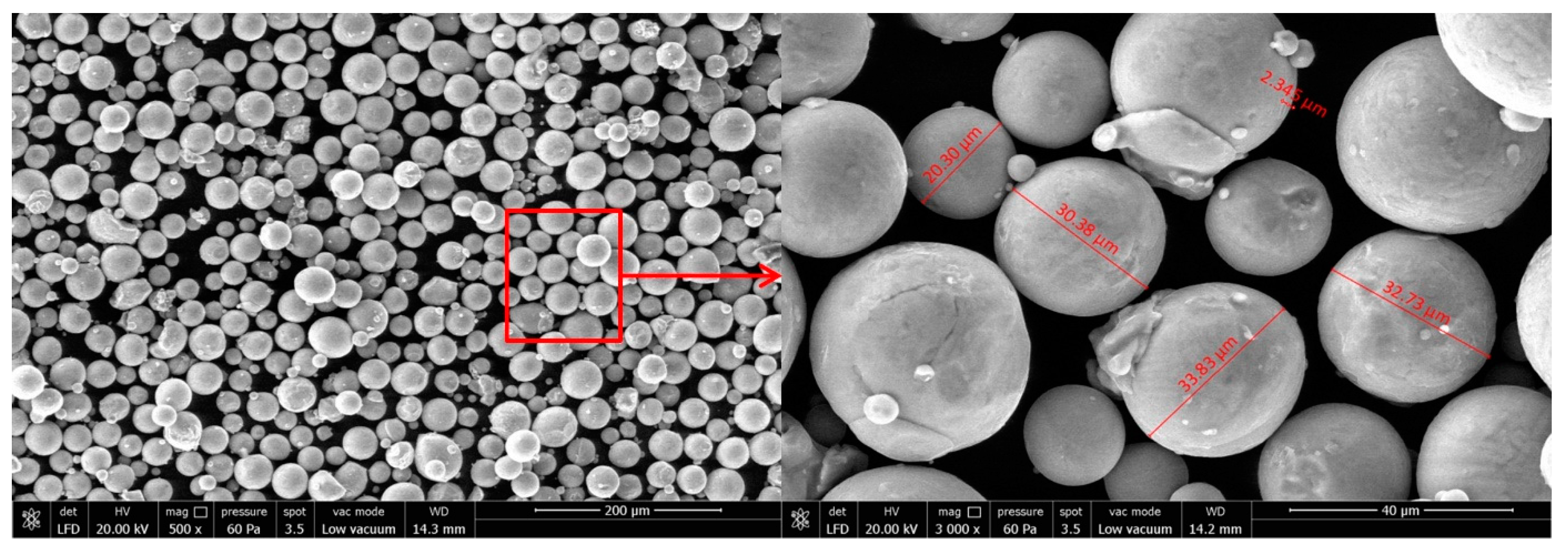
| Physical properties | Density (g/cm3) | Particle size (µm) | ||||||
| 4.42 | 30–50 | |||||||
| Layer Thickness (µm) | Laser Power (W) | Scanning Speed (mm/s) | Hatch Distance (mm) | Energy Density (J/mm2) |
|---|---|---|---|---|
| 30 | 170 | 1250 | 0.1 | 1.36 |
| Experiment Number | Spindle Speed, n (rpm) | Cutting Speed (m/min) | Feed per Tooth, fz (µm/Tooth) | Depth of Cut, ap (µm) | Cutting Length (mm) | Aim of the Experiment |
|---|---|---|---|---|---|---|
| 1 | 32,000 | 50.26 | 0.05, 0.1, 0.25, 0.5 1, 2, 5, 10 | 100 | 18 | Determination of the minimum chip thickness. Effect of the feed per tooth on surface roughness and burr formation |
| 2 | 35,000 | 54.9 | 4 | 25, 50 100, 200 | 18 | Effect of depth of cut on cutting force, surface roughness and burr formation |
| 3 | 5000 10,000 20,000 50,000 | 7.85 15.7 31.4 78.5 | 1 | 100 | 18 | Effect of spindle speed on cutting force, surface roughness and burr formation |
| SLM Ti-6Al-4V | Wrought Ti-6Al-4V | |
|---|---|---|
| Hardness (HV) | 368 ± 10.2 | 314 ± 8.6 |
| Tensile Strength (MPa) | 1086 ± 26.1 | 850 ± 18.4 |
| Elongation at break (mm) | 2.770 | 2.118 |
Disclaimer/Publisher’s Note: The statements, opinions and data contained in all publications are solely those of the individual author(s) and contributor(s) and not of MDPI and/or the editor(s). MDPI and/or the editor(s) disclaim responsibility for any injury to people or property resulting from any ideas, methods, instructions or products referred to in the content. |
© 2023 by the authors. Licensee MDPI, Basel, Switzerland. This article is an open access article distributed under the terms and conditions of the Creative Commons Attribution (CC BY) license (https://creativecommons.org/licenses/by/4.0/).
Share and Cite
Karakılınç, U.; Ergene, B.; Yalçın, B.; Aslantaş, K.; Erçetin, A. Comparative Analysis of Minimum Chip Thickness, Surface Quality and Burr Formation in Micro-Milling of Wrought and Selective Laser Melted Ti64. Micromachines 2023, 14, 1160. https://doi.org/10.3390/mi14061160
Karakılınç U, Ergene B, Yalçın B, Aslantaş K, Erçetin A. Comparative Analysis of Minimum Chip Thickness, Surface Quality and Burr Formation in Micro-Milling of Wrought and Selective Laser Melted Ti64. Micromachines. 2023; 14(6):1160. https://doi.org/10.3390/mi14061160
Chicago/Turabian StyleKarakılınç, Uçan, Berkay Ergene, Bekir Yalçın, Kubilay Aslantaş, and Ali Erçetin. 2023. "Comparative Analysis of Minimum Chip Thickness, Surface Quality and Burr Formation in Micro-Milling of Wrought and Selective Laser Melted Ti64" Micromachines 14, no. 6: 1160. https://doi.org/10.3390/mi14061160