Article

Trajectory Strategy Effects on the Material Characteristics in the WAAM Technique

1
HCMC University of Technology and Education, Ho Chi Minh City 71307, Vietnam
2
Department of Industrial Engineering and Management, National Kaohsiung University of Science and Technology, Kaohsiung 80778, Taiwan
3
Falcuty of Mechanical Engineering, Industrial University of Ho Chi Minh City, Nguyen Van Bao Street, Ward 4, Go Vap District, Ho Chi Minh City 70000, Vietnam
*
Authors to whom correspondence should be addressed.
Micromachines 2023, 14(4), 827; https://doi.org/10.3390/mi14040827
Submission received: 19 March 2023 / Revised: 6 April 2023 / Accepted: 7 April 2023 / Published: 8 April 2023
(This article belongs to the Special Issue Advanced Manufacturing Technology and Systems, 2nd Edition)

Abstract

:
The wire Arc Additive Manufacturing (WAAM) technique has evolved into a cutting-edge 3D printing technique. This study surveys the influences of trajectory on the characteristics of low-carbon steel samples generated by the WAAM technique. The results show that the grains in the WAAM samples are isotropic, with grain size numbers ranging from 7 to 12. Strategy 3, with a spiral trajectory, has the smallest grain size, while strategy 2, with a lean zigzag trajectory, has the largest. The variations in grain size are caused by differences in heat input and output during the printing process. The WAAM samples achieve a significantly higher UTS value than the original wire, demonstrating the WAAM technique’s benefit. Strategy 3, with a spiral trajectory, achieves the highest UTS value, 616.5 MPa, 24% higher than the original wire. The UTS values of strategy 1 (horizontal zigzag trajectory) and strategy 4 (curve zigzag trajectory) are comparable. WAAM samples have significantly higher elongation values than the original wire, with only 22% elongation. The sample with the highest elongation value, 47.2%, was produced by strategy 3. Strategy 2 has an elongation value of 37.9%. The value of elongation is proportional to the value of UTS. WAAM samples have average elastic modulus values of 95.8 GPa, 173.3 GPa, 92.2 GPa, and 83.9 GPa, corresponding to strategies 1, 2, 3, and 4. Only a strategy 2 sample has a similar elastic modulus value to the original wire. All samples have dimples on the fracture surface, indicating that the WAAM samples are ductile. These fracture surfaces’ equiaxial shape corresponds to the original microstructure’s equiaxial shape. The results provide the optimal trajectory for the WAAM products is the spiral trajectory, while the lean zigzag trajectory gains only modest characteristics.

1. Introduction

In recent decades, additive manufacturing (AM) has become popular [1,2,3]. In this technique, the products are usually added or fabricated layer by layer from 3D model data, which differs from the traditional subtractive methods. The technique’s most valuable feature is its ability to construct a complex object accurately. A 3D printer is easy to use if the 3D model data file is available, making it suitable for industrial and educational purposes. Moreover, 3D printing is also an advanced selection when manufacturers want to create rapid prototypes during the design process, as it can save time and cost. In fact, rapid prototyping is the initial application of 3D printing before it can be applied to mass production. Based on the way the raw materials are solidified, AM could be classified as fused deposition modeling (FDM), stereolithography (SL), selective laser sintering (SLS), electron beam melting (EBM), and wire arc additive manufacturing (WAAM). However, some drawbacks prevent it from becoming a more dominant technique, such as requiring much energy, time, and expensive equipment [4,5,6]. As a result, additive manufacturing applications are still limited in some areas, such as automotive, aerospace, biomedical, machinery, and robotics [7,8,9]. Wire shape materials save significantly more energy and time than powder travel materials. In accordance, it is more widely used in industries than powder materials.
WAAM technique uses an electrical arc as a heating source for melting wires [10,11,12,13]. WAAM could produce parts with large sizes, low costs, and high-efficiency thanks to the accessibility of wires, arc sources, and mechanical devices [14,15]. As a result, many authors have discussed the WAAM process’s parameter optimization [16,17,18,19,20]. Ke et al. [21], for instance, suggested that ultra-high-frequency pulses were used to refine the grain structure and produce a high-quality WAAM product. With the assistance of ultra-high-frequency pulsed, the molten pool of the NiTi shape memory alloys is vibrated, leading to the refinement of the grain structure. Henckell et al. [22] tried to minimize energy input by employing a short arc welding regime, thereby improving the shape and microstructure of WAAM samples. Applying a brief arc welding regime, the input energy might reduce from 10% to 40%. As a result, the cooling rate improves, leading to a decrease in grain size [23].
Bambach et al. [24] investigated the machining process of titanium alloy Ti-6Al-4 V using metal forming and the WAAM technique for aerospace products. Firstly, a semi-finished shape is created via the WAAM process. Then, this part is forged and heat-treated. The ultimate tensile strength and the ductility of the final product are as good as the traditional forged products. This combination is beneficial when fabricating complex products that require many forging steps. The WAAM technique was used by Shen et al. [25] to create iron-rich Fe-Al intermetallic alloys. They noted that the printed sample obtained a higher yield strength and a similar ductility compared to conventional powder metallurgy. Interestingly, the repeated heating step during the WAAM process created an in situ alloying phenomenon, leading to high alloy mixing. Additionally, Ti6Al4V produced using the plasma arc WAAM technique can outperform the aeronautical industry’s requirements, as shown by Veiga et al. [26]. Notably, the mechanical properties of the product present an anisotropy characteristic. Dong et al. [27] investigated Al-Zn-Mg-Cu alloy and revealed the existence of precipitation of nanoscale second phases during the WAAM process. In the vertical direction, the average tensile strength and yield strength are higher than in the horizontal direction [28]. The continuity and the porosity play as crack sources, creating the weakness of the alloy. According to Alonso et al. [29], Ti6Al4V alloy made by the WAAM technique requires more significant force, shorter chips, and shorter burr when compared to a traditional laminated plate. The reason is that the hardness of the WAAM sample is higher than the conventional laminated plate.
Besides controlling the electrical conditions, adjusting the printing trajectory can improve the 3D printing parts. For instance, Shembekar et al. [30] applied a 6-DOF robot to fabricate a 3D printing part with a collision-free trajectory. They achieved a good surface finish quality with reasonable printing time. Gardan et al. [31] increased the fracture toughness of the 3D printing sample by a principal stress direction design before printing. This special design improves fracture toughness by 20% compared to the classical method. Interestingly, Huang et al. [32] implied that special structures such as the Messerschmitt-Bölkow-Blohm and cantilever beams could enormously enhance the structural stiffness of the thermoplastic composite beam. Optimizing the trajectory during the multi-objects printing process can significantly decline the printing time, as presented in Luo et al. report [33]. Unlike traditional slicing software, this method calculated the optimal pathway between every two objects to create a continuous path, avoiding the collision phenomenon. The impacts of the printing angle between the feed orientation and the printing pathway tangent on the complex-shaped samples are discussed in the Kalashnikov et al. [34] report. The repeated heating cycle during the WAAM process leads to a coarsening in the grain structure, reducing the mechanical properties [35,36]. However, the effects of printing trajectory on the WAAM technique are rarely discussed. The investigation of printing trajectory is essential because various trajectories might result in different product characteristics.
In this report, we investigate the effects of printing trajectory on the microstructure and mechanical properties of the printed sample using the WAAM process. The WAAM process is carried out on a regular CNC machine and a MAG welding machine. The effects of the horizontal zigzag, lean zigzag, spiral, and curve zigzag strategy trajectories on the tensile properties and microstructure of the samples are investigated. The results could provide the optimal trajectory for the WAAM products.

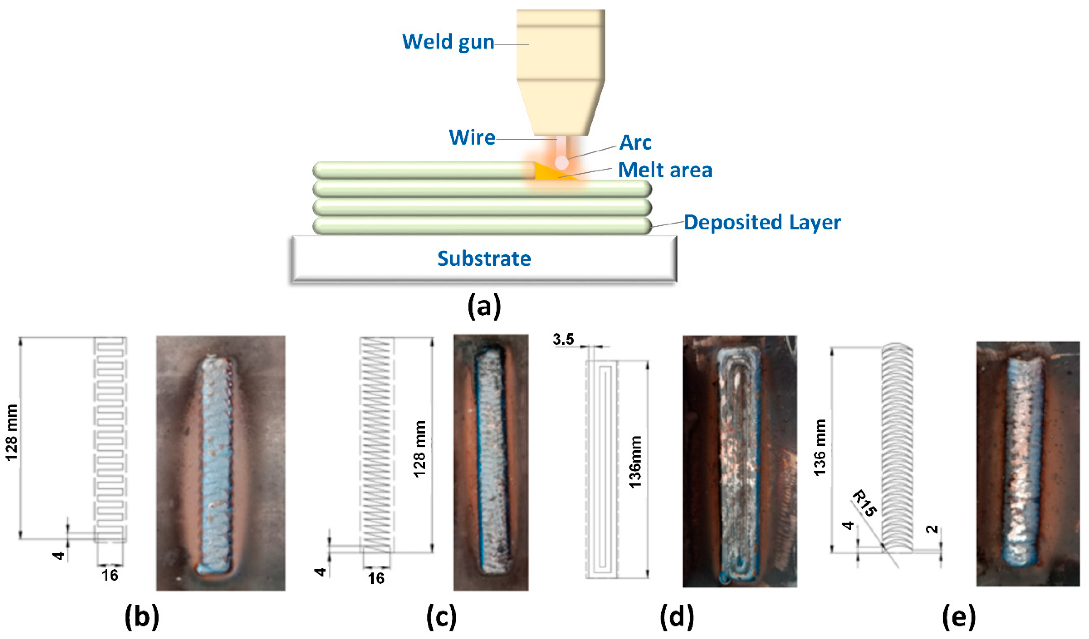
2. Experimental Methods

Figure 1 shows the WAAM process and the welding strategy with different trajectories. The sample block is generated via printing layer by layer. In each layer, the weld gun moves in different trajectories, including strategy 1 with a horizontal zigzag trajectory, strategy 2 with a lean zigzag trajectory, strategy 3 with a spiral trajectory, and strategy 4 with a curve zigzag trajectory. The welding gun is located on a standard CNC machine and can move in different trajectories during printing. A steel base is prepared for printing the sample block. The steel base is cooled and fixed on the CNC machine to prevent the printed sample from being twisted due to the high thermal energy of the WAAM process. The mechanical and chemical properties of the S20C steel base are shown in Table 1 and Table 2. The welding machine uses steel wire with grade AWS A5.18 ER 70S-6, having a 0.8 mm diameter. The welding wire’s mechanical and chemical properties with grade AWS A5.18 ER 70S-6 are shown in Table 3 and Table 4. After machining sample blocks, they are machined to have three small samples in accordance with ASTM E8/E8M -13 standards before the tensile test. The steel blocks are cut to the tensile standard using wire electrical discharge machining (WEDM) to ensure dimension accuracy and avoid severe impact on the microstructure that could appear using traditional cutting methods. The welding parameters are selected as U = 22 V, I = 120 A, 400 mm/min travel rate, and 10 litter per min CO2 flow rate. In this study, the welding parameters are selected as U = 22 V, I = 120 A, 400 mm per min travel rate, and 10 litter per min CO2 flow rate. The weld heat input Q could be calculated as:
Q = U × I T r a v e l   r a t e   ( m m s ) × ƞ
where Q is the weld heat input (Joule/mm); ƞ is the weld thermal efficiency, which ranges from 69% to 91% for the GMAW technique. The calculated weld heat input Q in this study ranges from 274 J/mm to 360 J/mm, which is compatible with Kumar et al. [37,38] report. Moreover, the weld heat input depends on the sample thickness, wire diameter, and especially wire material. The target wall thickness also impacts the weld heat input value [39]. For the A5.18 ER 70S-6 welding wire, before experimenting, we also tried to test with some parameters that could create good samples. In this study, we focus on the welding strategy. In further investigation, we would try to survey more about the effect of the weld heat input for A5.18 ER 70S-6 welding wire.
The tensile test machine (SANS model CHT4106, China) is used to investigate the mechanical characteristics of the sample. In this study, the test pieces are horizontal to the steel base because the designed trajectory presents its impact most in this direction. The designed trajectory focuses on the horizontal factor. Therefore, we fabricated the size of the printing block suitable for the horizontal samples. Before observing the metallurgical microstructure, the samples are polished by the grinding polishing MP-2B machine, and etched by Nital 4% solution. The microstructure of these samples is tested using a scanning electron microscope (SEM5410 LV, JEOL, Japan) and a metallurgy microscope (Oxion OX.2153-PLM EUROMEX, Holland).

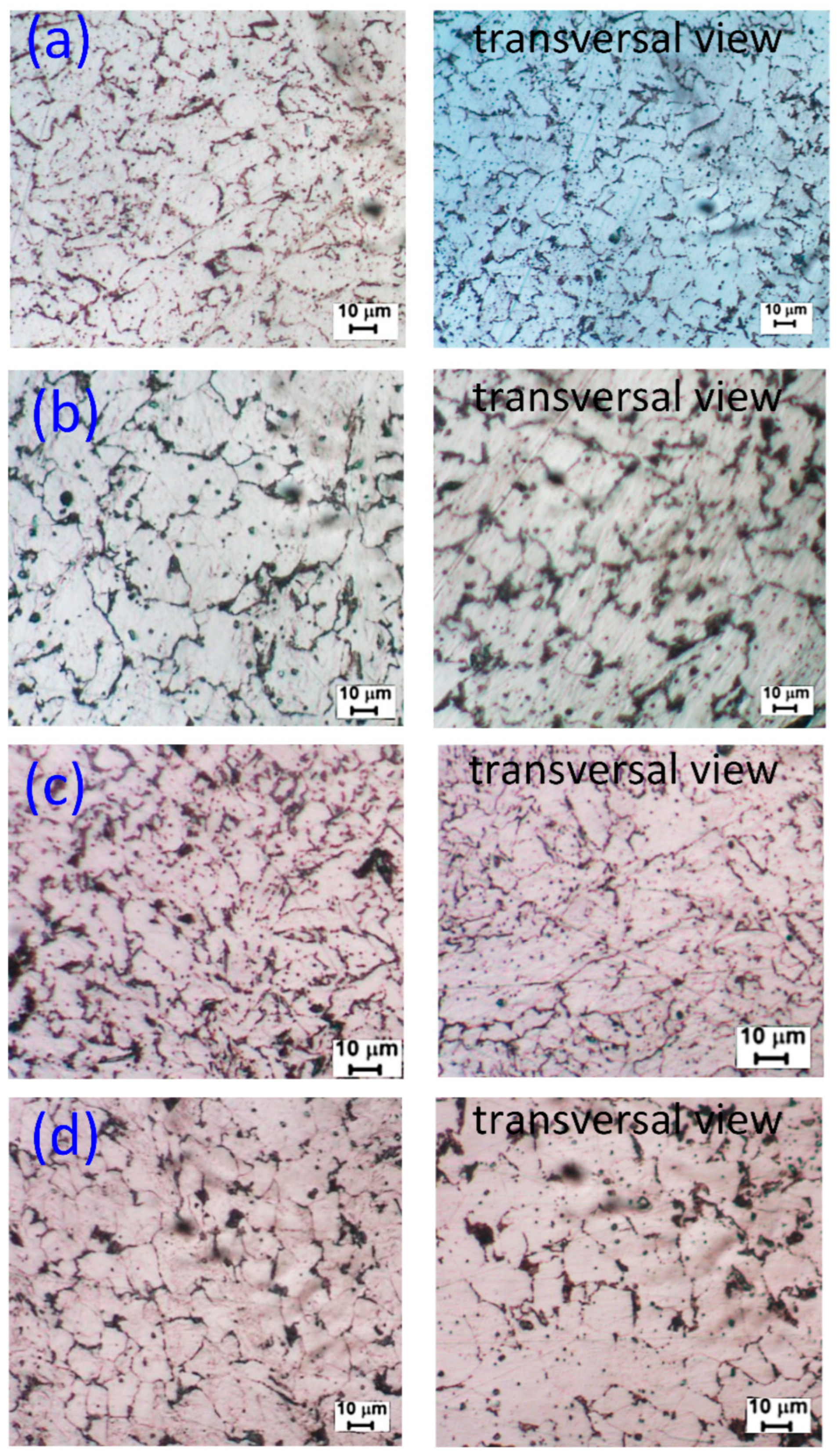
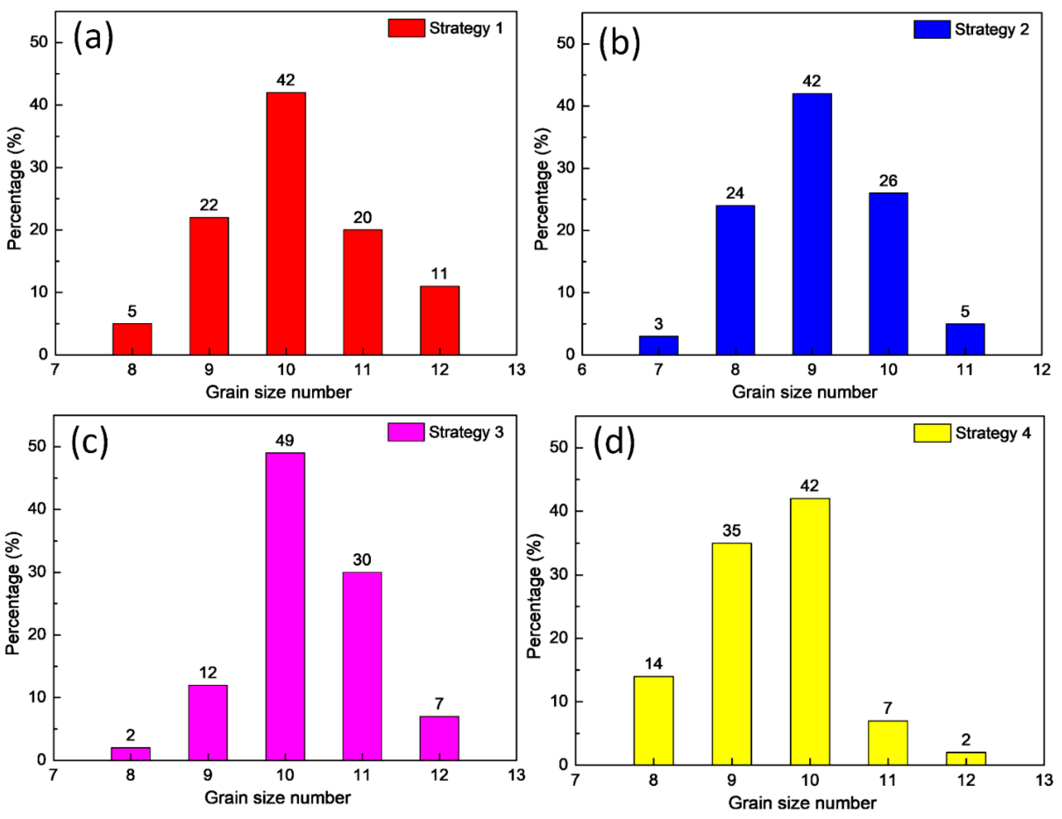
3. Results and Discussion
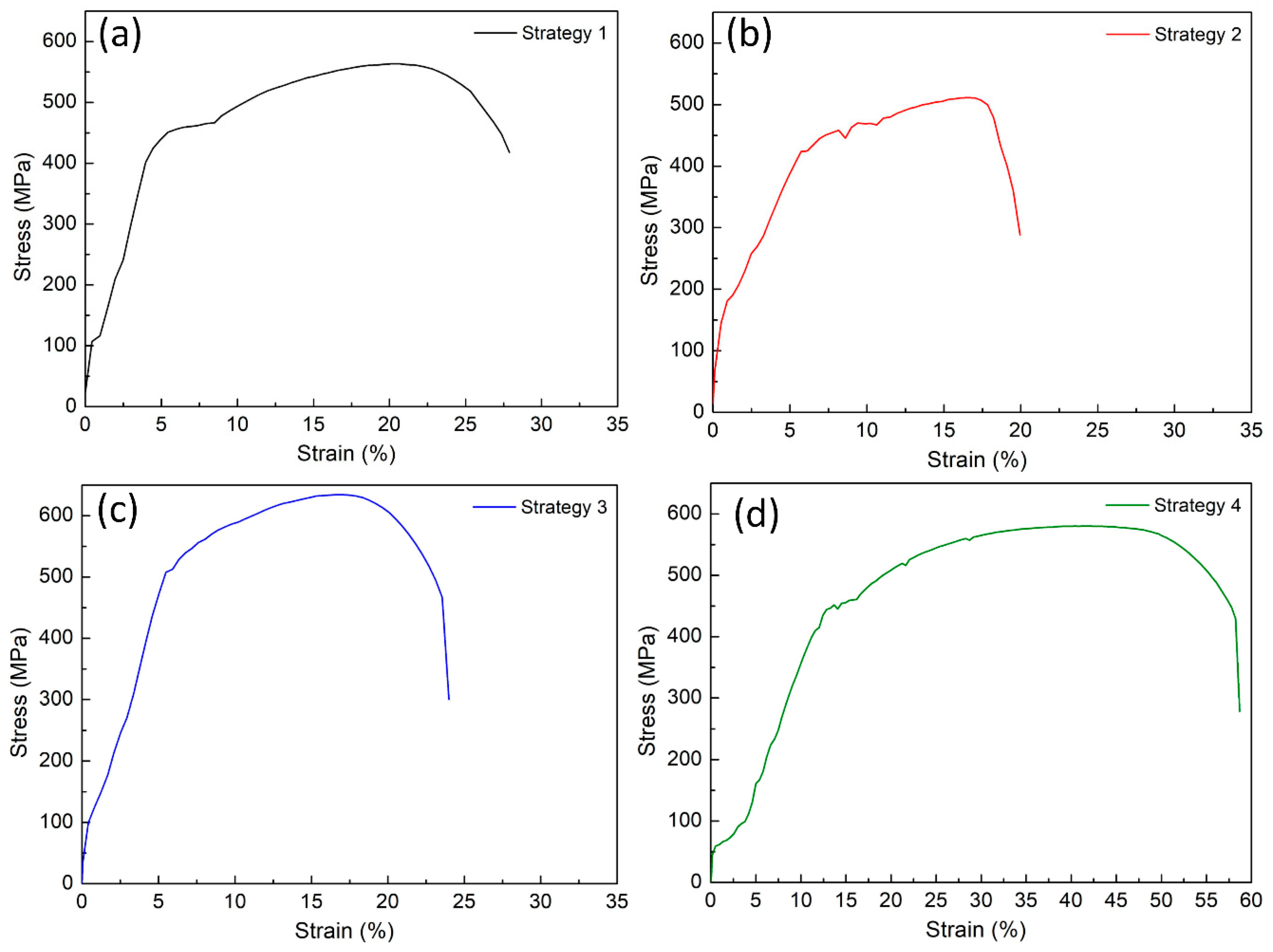
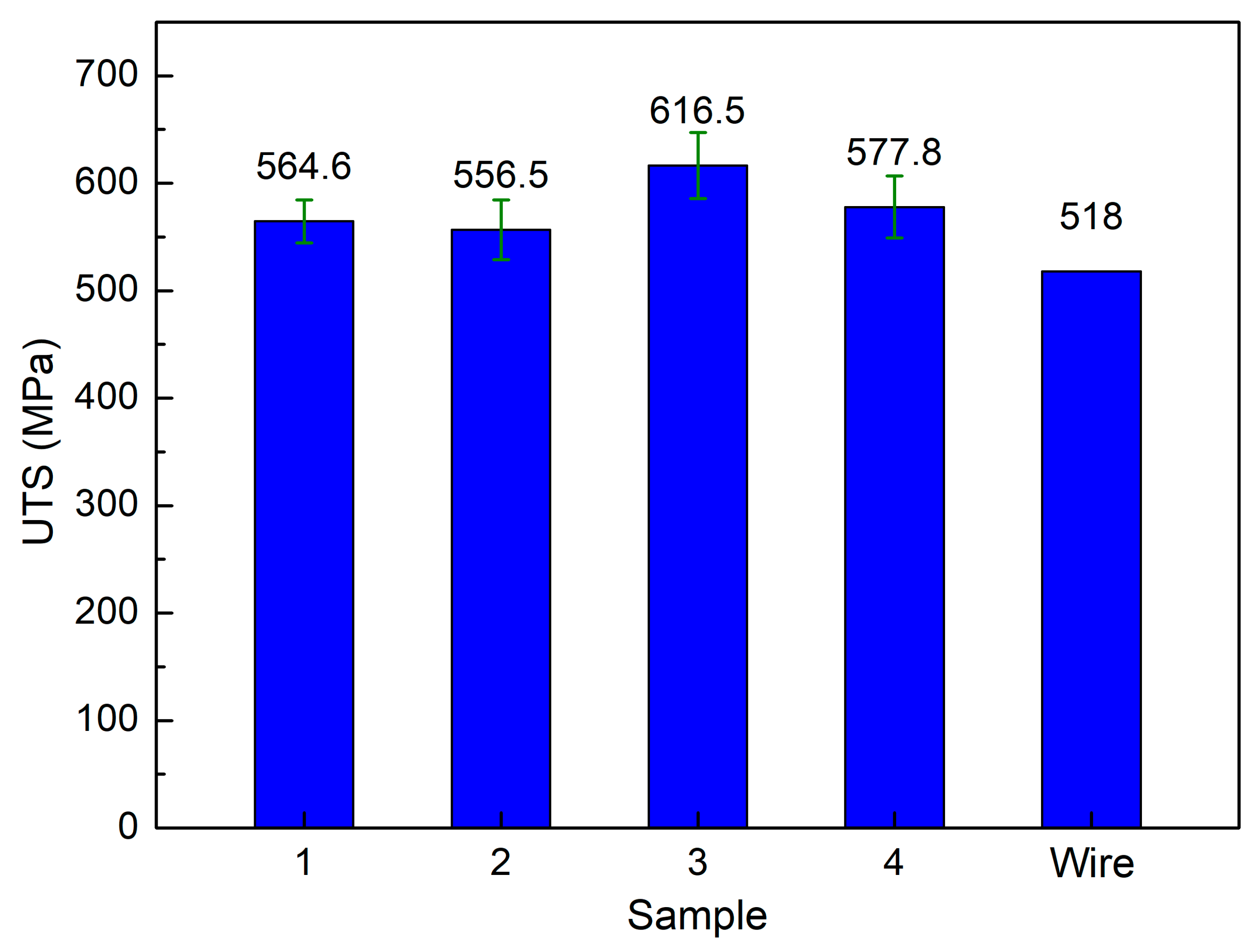
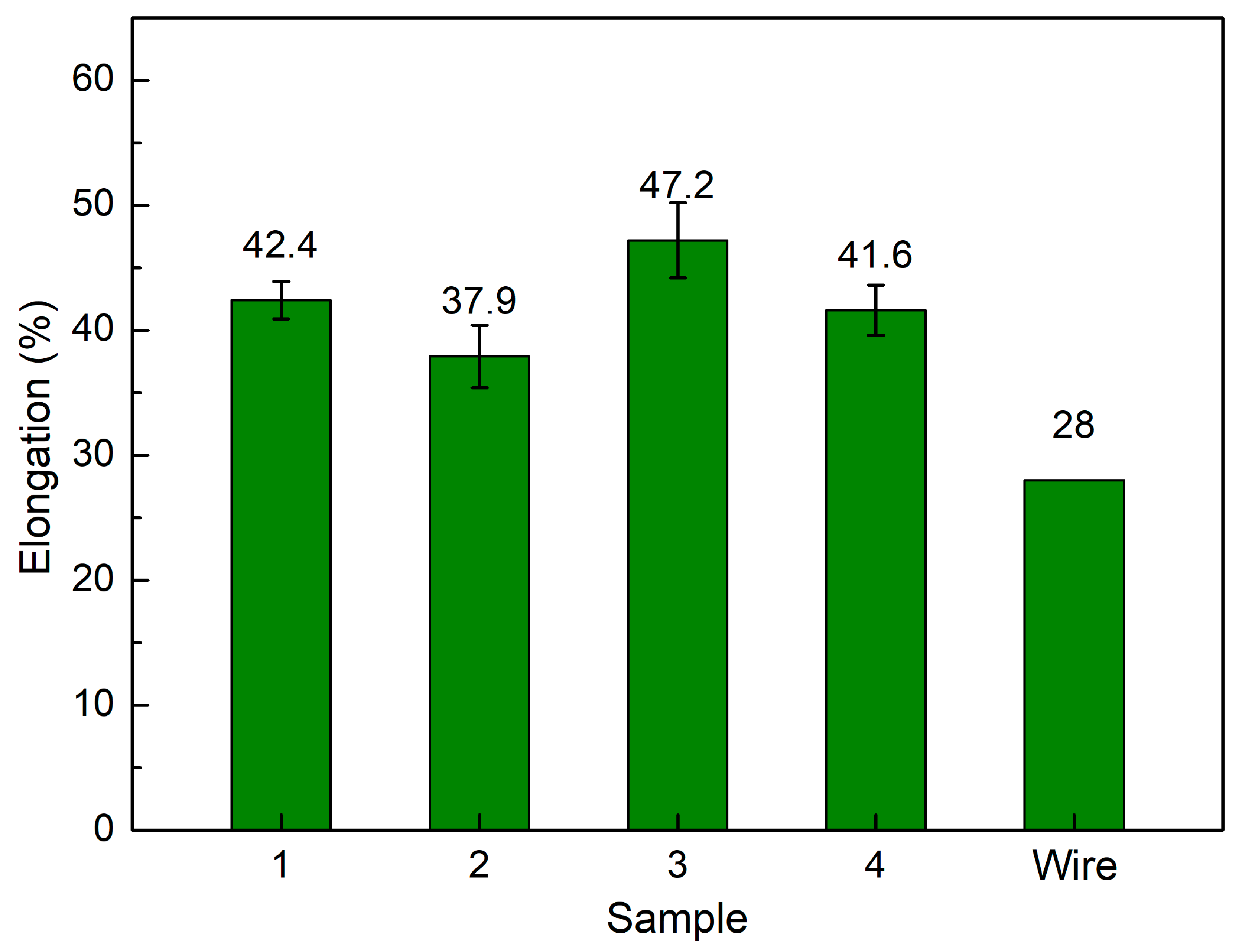
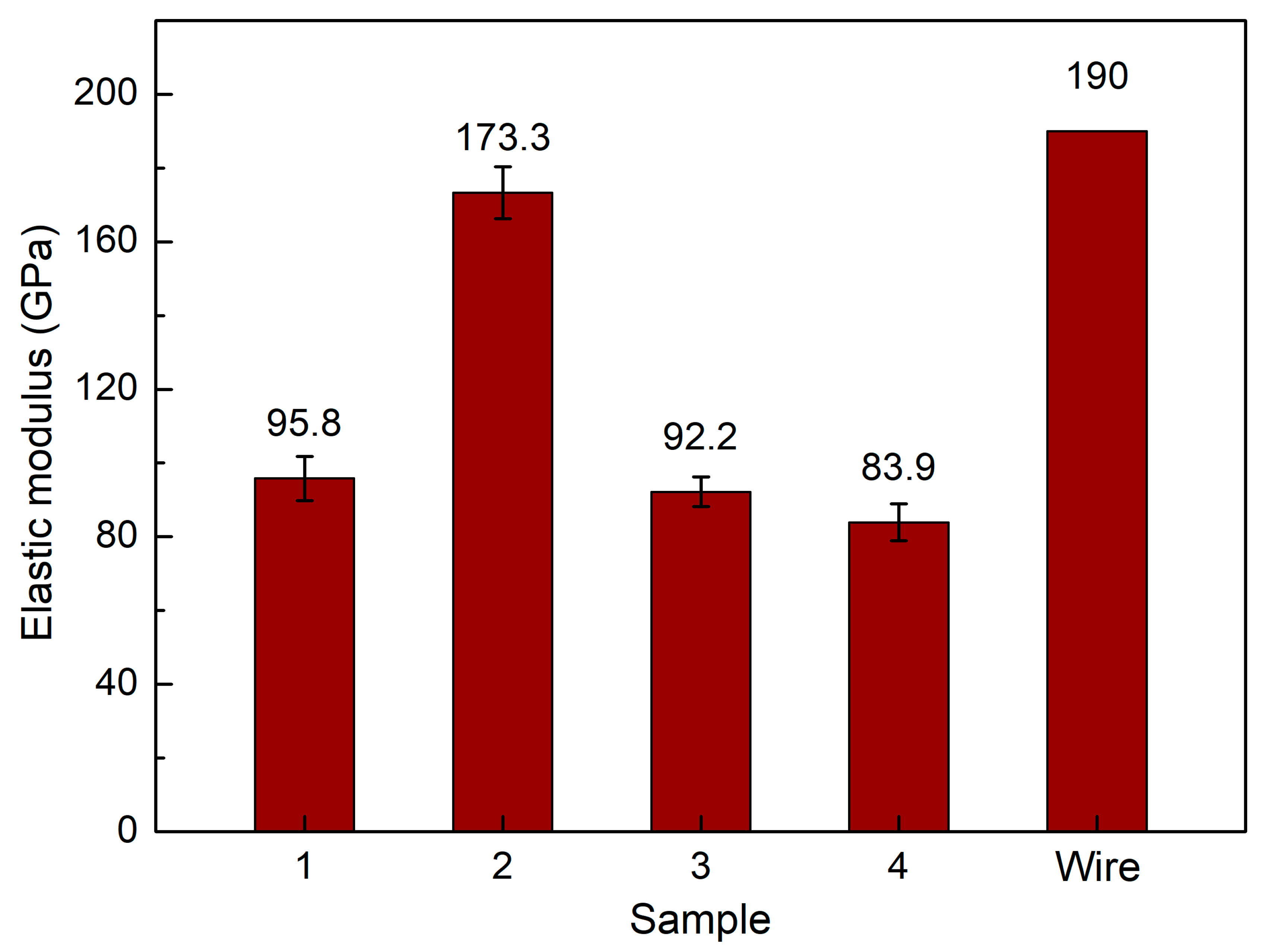
The metallurgy microstructures of the samples at different WAAM strategies are shown in Figure 2. The black phase that scatters on the matrix is pearlite, and the white matrix is ferrite. The dominant ferrite phase indicates that this sample is low-carbon steel, consistent with the wire grade AWS A5.18 ER 70S-6. Moreover, the microstructure images in a normal direction and their transverse images show that most grains on the microstructure have a polygonal and relatively equiaxial shape, consistent with other studies [40,41,42,43]. In Kumar et al. [38] report, they also generated a WAAM sample using AWS A5.18 ER 70S-6 welding wire and straight trajectory. The microstructure of those samples is also polygonal ferrite with a small amount of pearlite.
Moreover, the microstructure test piece is machined from the printing block, not from connecting two steel parts. Therefore, we can conclude that the microstructure occurs at the center of the weld bead, presenting a relatively equiaxial shape. Notably, before being melted to create WAAM samples, the original welding wire has an anisotropy shape due to the initial drawing process of the steel wire. The melting of the solidification process enormously transforms the microstructure of the wire compared to the printing samples. From these figures, we can also analyze the grain size of these samples. The grain size number strongly affects the yield strength of the alloys [44]. To further investigate these microstructures, Figure 3 reveals the grain size number of the WAAM samples.
Figure 3 displays the grain size number distribution of WAAM samples at different WAAM strategies. The grain dimensions are measured via ImageJ software and classified using the ASTM E112-10 standard. Overall, the grain size numbers vary around 7–12. The average grain area values are 131 µm2, 245 µm2, 107 µm2, and 193 µm2, correspondings to samples of strategies 1, 2, 3, and 4. The results show that the WAAM strategy strongly impacts the grain size of the samples. Strategy 3 has the smallest grain size, while strategy 2 has the largest. The printing trajectory affects the level of cooling during the printing process, and different WAAM strategies produce different levels of cooling or solidification, affecting the sample grain size. Repeatedly and briefly heating the grain could make the grain size larger.
On the contrary, in the trajectory where the heating cycle is longer, the grain tends to become smaller. As seen in Figure 1d, strategy 3 with the spiral pathway makes it more time and space to release the thermal energy during the WAAM process. Therefore, it has the smallest grain size compared to other cases. Strategy 1 with horizontal zigzag also has a relatively small grain size compared to other cases. On the other hand, strategies 2 and 4 have much denser printing trajectories. Because the printing layers are strongly heated up during the printing process, the grain size has enough energy to grow, producing a coarser microstructure.

Tensile Strength

Figure 4 demonstrates the tensile test diagram of samples at different WAAM strategies. The average values of the ultimate tensile strength (UTS) are summarized in Figure 5. The UTS values for strategies 1, 2, 3, and 4 are 564.6 MPa, 556.5 MPa, 616.5 MPa, and 577.8 MPa, respectively. Compared to the original wire’s UTS value of 496.4 MPa, the WAAM samples achieve an exceptionally higher UTS value, demonstrating the advantage of the WAAM technique. In Shirizly et al. [45] report, they also constructed a WAAM sample using AWS A5.18 ER 70S-6 welding wire and axisymmetric trajectory. The average tensile strength is 537 MPa, close to this study result and higher than the original wire. Compared to Gou et al. [46] study, which used the sample welding wire and straight trajectory, that research reached a UTS value of 500 MPa, which is also lower than this study’s result. The macro and microstructures produced from a designed trajectory combined with the melting and solidification process generate an advanced microstructure that enhances the UTS value. Strategy 1 and Strategy 4 have similar UTS values of 564.6 MPa and 577.8 MPa, respectively.
Furthermore, strategy 3 with spiral trajectory achieves the highest UTS value of 616.5 MPa, 19% higher than the original wire. This variation is due to the Hall-Petch equation, in which the smaller grain size presents a higher strength [44]. Because strategy 3 has the smallest grain size, it achieves the highest tensile strength value. The printing trajectory affects the level of cooling during the printing process [38]. Different WAAM strategies produce different cooling or solidification levels, affecting sample grain size. Repeatedly heating the grain for short periods could make the grain size larger.
On the contrary, in the trajectory where the heating cycle is longer, the grain tends to become smaller. As seen in Figure 1d, strategy 3 with the spiral pathway makes it more time and space to release the thermal energy during the WAAM process. Therefore, it has the smallest grain size compared to other cases. Strategy 2, with a lean zigzag trajectory, on the other hand, has the lowest UTS value, which is 7% lower than the original wire as it has the largest grain size, as presented in Figure 3. Besides, macrostructure and defects also impact sample characteristics.
Figure 6 shows the average elongation of samples at different WAAM strategies, WAAM samples have average elongation values of 42.4%, 37.9%, 47.2%, and 41.6%, corresponding to strategies 1, 2, 3, and 4, and these WAAM samples have significantly higher elongation values than the original wire, which is only 28%. With the same technique and axisymmetric trajectory, the WAAM sample could elongate by 24%, which is lower than this study’s results [37]. With a straight trajectory, the elongation of the WAAM sample could be 19%, which is also lower than this study, indicating the advance of complex trajectories in enhancing ductility. During the printing in each layer and between layers, the heating energy repeatedly anneals the sample; therefore, the sample is gradually softened, and the ductility is improved. The sample produced by strategy 3 has the highest elongation value. Strategy 2 has the lowest elongation value. Remarkably, the high UTS sample has a high or elongation value proportional to UTS. In other words, the sample has a higher UTS value and also a higher elongation value. The elongation values are also consistent with the grain size value, in which the smaller grain size has the higher elongation value, indicating the important role of grain size on the mechanical properties of the WAAM sample. The advancement of printing trajectory leads to an improvement in the WAAM sample elongation, similar to an increase in UTS value.
Figure 7 shows the average elastic modulus of samples at different WAAM strategies. WAAM samples have average elastic modulus values of 95.8 GPa, 173.3 GPa, 92.2 GPa, and 83.9 GPa, corresponding to strategies 1, 2, 3, and 4. Compared to the Gou et al. [46] study, which gains an elastic modulus of 208 GPa, this study has a lower elastic value. However, this study’s UTS and elongation values are higher than those that study. Only a sample with strategy 2 has a similar elastic modulus value to the original wire. This result is consistent with the elongation value, in which the lowest elongation sample has the highest elastic modulus of 173.3 GPa due to the stiffness of this sample. Besides, the trajectory of different strategies also impacts the elastic modulus value of the WAAM sample. Therefore, although the elongation values between these strategies are not so different, the elastic modulus of strategy 2 is significantly higher than in other cases. Other samples printed with strategies 1, 3, and 4 have substantially lower elastic modulus values than strategy 2. The strategy 4 sample has the lowest elastic modulus of 83.3 Gpa. The reason for this low elastic modulus value is related to the high elongation value compared to the original wire. As mentioned, the heating cycle of the WAAM process anneals the sample, resulting in a more ductile characteristic with higher elongation and lower elastic modulus.
After the tensile test, the fracture surface of the WAAM sample is observed via SEM microstructure. The SEM fracture surfaces of samples at different WAAM strategies are displayed in Figure 8. The failure in Figure 8 is observed in the fracture surface of the tensile test. In contrast, the tensile test piece is machined from the printing block, and therefore, the failure occurs at the center of the weld bead. The dimple shapes appear on the fracture surface of all samples, indicating the ductile characteristic of the WAAM samples [47]. These fracture surfaces’ equiaxial shape also represents the original microstructure’s equiaxial shape, as shown in Figure 2.
Additionally, the dimples’ size reveals the WAAM samples’ microstructure. Strategy 3 shows the smallest dimple size (Figure 8c), while strategy 2 presents the largest dimple size (Figure 8b). These results are consistent with the grain size, as shown in Figure 3.

4. Conclusions

This study surveys the effects of trajectory on the characteristics of WAAM steel samples. The following exciting notes to be mentioned are:
-
The grains in the WAAM samples are isotropic, and their grain size number values range from about 7 to 12. The grain size of strategy 3 with spiral trajectory is the smallest, while strategy 2 with lean zigzag has the largest. This difference could result from the printing process’s heat input or storage;
-
The WAAM samples achieve a significantly higher UTS value than the original wire, proving the benefit of the WAAM technique. The highest UTS value, 616.5 MPa, is attained by strategy 3 with a spiral trajectory. The lowest UTS value for strategy 2, which has a lean zigzag trajectory, is 556.5 Mpa;
-
WAAM samples have significantly higher elongation values than the original wire, with an elongation value of only 22%. Strategy 3 produced the sample with the highest elongation value of 47.2%, and the elongation value of Strategy 2 was 37.9%. The elongation value is proportional to the UTS value;
-
WAAM samples have average elastic modulus values of 95.8 GPa, 173.3 GPa, 92.2 GPa, and 83.9 GPa, corresponding to strategies 1, 2, 3, and 4. Only a sample with strategy 2 has a similar elastic modulus value to the original wire;
-
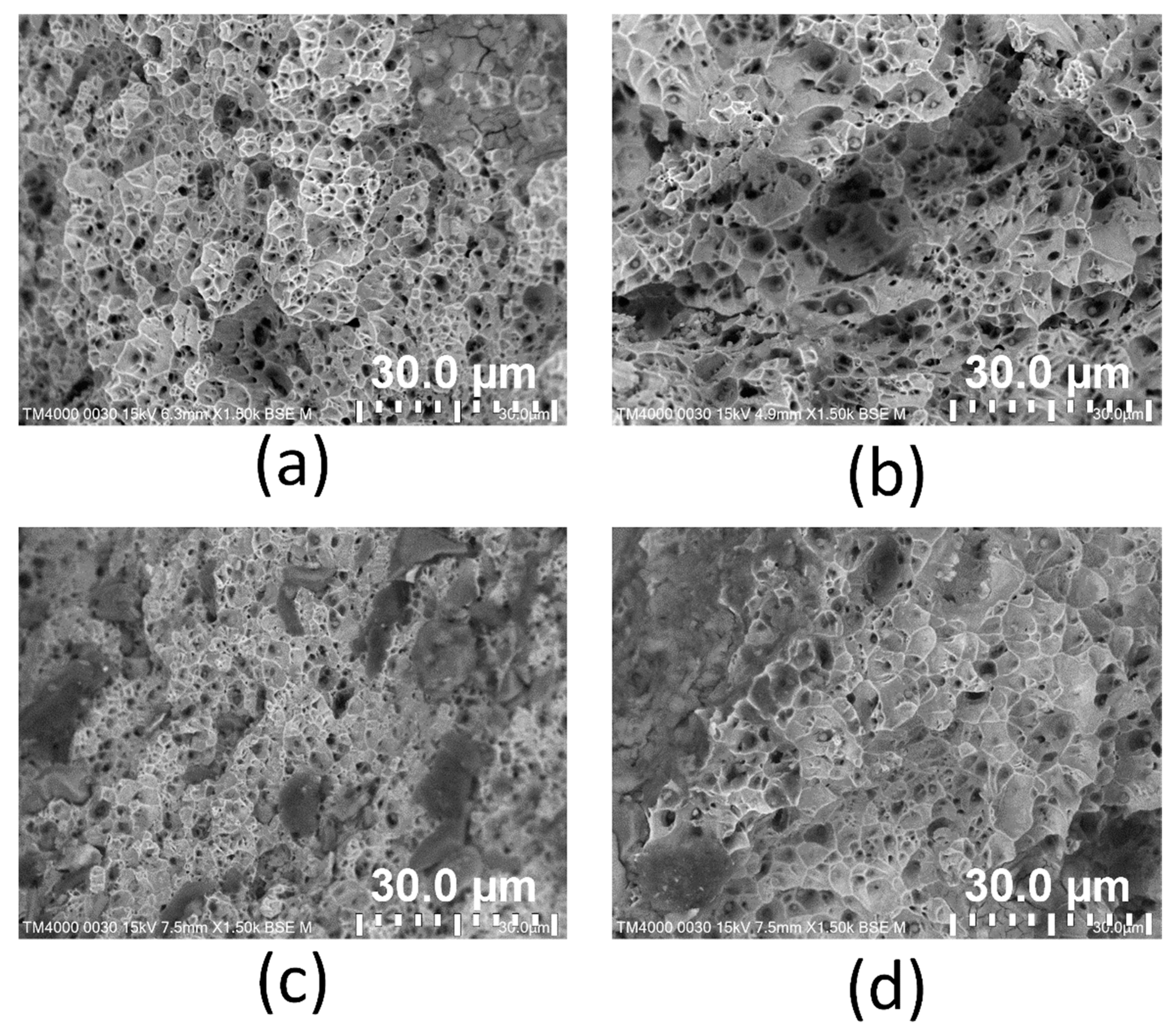
The dimples shape appears on the fracture surface of all samples, indicating that the WAAM samples are ductile. The equiaxial shape of these fracture surfaces corresponds to the original microstructure’s equiaxial shape. The results provide the optimal trajectory for the WAAM products is a spiral trajectory, while the lean zigzag trajectory only gains modest mechanical characteristics.

Author Contributions

T.M.T.U. and V.-T.N.: Conceptualization, funding acquisition; V.-T.N.: writing original draft, investigation; V.T.N. and V.-T.N.: analysing, visualization; T.M.T.U., P.S.M. and V.-T.N.: project administration; T.T.D., P.S.M. and M.-T.L.: investigation; V.T.T.N., P.S.M. and V.-T.N.: writing, review and editing. All authors have read and agreed to the published version of the manuscript.

Funding

This research was funded by the Ministry of Education and Training, project Grant No. B2021-SPK-04, and hosted by Ho Chi Minh City University of Technology and Education, Vietnam, and Micromachines Editorial Office funded the APC.

Institutional Review Board Statement

Not applicable.

Informed Consent Statement

Not applicable.

Data Availability Statement

The data used to support the findings of this study are available from the corresponding author upon request.

Acknowledgments

The authors acknowledge the support of the HCMC University of Technology and Education for this study, thanks Chau Tan Phuoc, Le Anh Vu, Thai Huy Hoang for their assistance with and discussions surrounding the experiments.

Conflicts of Interest

The authors declare no conflict of interest.

References

  1. Harun, W.S.W.; Kamariah, M.S.I.N.; Muhamad, N.; Ghani, S.A.C.; Ahmad, F.; Mohamed, Z. A review of powder additive manufacturing processes for metallic biomaterials. Powder Technol. 2018, 327, 128–151. [Google Scholar] [CrossRef]
  2. Liu, G.; Zhang, X.; Chen, X.; He, Y.; Cheng, L.; Huo, M.; Yin, J.; Hao, F.; Chen, S.; Wang, P. Additive manufacturing of structural materials. Mater. Sci. Eng. R Rep. 2021, 145, 100596. [Google Scholar] [CrossRef]
  3. Ivanova, O.; Williams, C.; Campbell, T. Additive manufacturing (AM) and nanotechnology: Promises and challenges. Rapid Prototyp. J. 2013, 19, 353–364. [Google Scholar] [CrossRef] [Green Version]
  4. Huang, S.H.; Liu, P.; Mokasdar, A.; Hou, L. Additive manufacturing and its societal impact: A literature review. Int. J. Adv. Manuf. Technol. 2013, 67, 1191–1203. [Google Scholar] [CrossRef]
  5. Zocca, A.; Colombo, P.; Gomes, C.M.; Günster, J. Additive manufacturing of ceramics: Issues, potentialities, and opportunities. J. Am. Ceram. Soc. 2015, 98, 1983–2001. [Google Scholar] [CrossRef]
  6. Baumers, M.; Dickens, P.; Tuck, C.; Hague, R. The cost of additive manufacturing: Machine productivity, economies of scale and technology-push. Technol. Forecast. Soc. Change 2016, 102, 193–201. [Google Scholar] [CrossRef]
  7. Guo, N.; Leu, M.C. Additive manufacturing: Technology, applications and research needs. Front. Mech. Eng. 2013, 8, 215–243. [Google Scholar] [CrossRef]
  8. Liu, R.; Wang, Z.; Sparks, T.; Liou, F.; Newkirk, J. Aerospace applications of laser additive manufacturing. In Laser Additive Manufacturing; Woodhead Publishing: Amsterdam, The Netherlands, 2017; pp. 351–371. [Google Scholar]
  9. Zhang, G.Q.; Mondesir, W.; Martinez, C.; Li, X.; Fuhlbrigge, T.A.; Bheda, H. Robotic additive manufacturing along curved surface—A step towards free-form fabrication. In Proceedings of the 2015 IEEE International Conference on Robotics and biOmimetics (Robio), Zhuhai, China, 6–9 December 2015; pp. 721–726. [Google Scholar]
  10. Wu, B.; Pan, Z.; Ding, D.; Cuiuri, D.; Li, H.; Xu, J.; Norrish, J. A review of the wire arc additive manufacturing of metals: Properties, defects and quality improvement. J. Manuf. Process. 2018, 35, 127–139. [Google Scholar] [CrossRef]
  11. Cunningham, C.R.; Flynn, J.M.; Shokrani, A.; Dhokia, V.; Newman, S.T. Invited review article: Strategies and processes for high quality wire arc additive manufacturing. Addit. Manuf. 2018, 22, 672–686. [Google Scholar] [CrossRef]
  12. Dhinakaran, V.; Ajith, J.; Fahmidha AF, Y.; Jagadeesha, T.; Sathish, T.; Stalin, B. Wire Arc Additive Manufacturing (WAAM) process of nickel based superalloys—A review. Mater. Today Proc. 2020, 21, 920–925. [Google Scholar] [CrossRef]
  13. Thapliyal, S. Challenges associated with the wire arc additive manufacturing (WAAM) of aluminum alloys. Mater. Res. Express 2019, 6, 112006. [Google Scholar] [CrossRef]
  14. Singh, M.; Sharma, S.; Muniappan, A.; Pimenov, D.Y.; Wojciechowski, S.; Jha, K.; Dwivedi, S.P.; Li, C.; Królczyk, J.B.; Walczak, D.; et al. In Situ Micro-Observation of Surface Roughness and Fracture Mechanism in Metal Microforming of Thin Copper Sheets with Newly Developed Compact Testing Apparatus. Materials 2022, 15, 1368. [Google Scholar] [CrossRef] [PubMed]
  15. Shah, R.; Pai, N.; Rosenkranz, A.; Shirvani, K.; Marian, M. Tribological Behavior of Additively Manufactured Metal Components. J. Manuf. Mater. Process. 2022, 6, 138. [Google Scholar] [CrossRef]
  16. Montevecchi, F.; Venturini, G.; Scippa, A.; Campatelli, G. Finite element modelling of wire-arc-additive-manufacturing process. Procedia Cirp 2016, 55, 109–114. [Google Scholar] [CrossRef] [Green Version]
  17. Taşdemir, A.; Nohut, S. An overview of wire arc additive manufacturing (WAAM) in shipbuilding industry. Ships Offshore Struct. 2021, 16, 797–814. [Google Scholar] [CrossRef]
  18. Çam, G. Prospects of producing aluminum parts by wire arc additive manufacturing (WAAM). Mater. Today Proc. 2022, 62, 77–85. [Google Scholar] [CrossRef]
  19. Huynh, T.T.; Nguyen TV, T.; Nguyen, Q.M.; Nguyen, K.T. Minimizing warpage for mac-ro-size fused deposition modeling parts. Comput. Mater. Contin. 2021, 68, 2913–2923. [Google Scholar]
  20. Graf, M.; Hälsig, A.; Höfer, K.; Awiszus, B.; Mayr, P. Thermo-mechanical modelling of wire-arc additive manufacturing (WAAM) of semi-finished products. Metals 2018, 8, 1009. [Google Scholar] [CrossRef] [Green Version]
  21. Ke, W.C.; Oliveira, J.P.; Cong, B.Q.; Ao, S.S.; Qi, Z.W.; Peng, B.; Zeng, Z. Multi-layer deposition mechanism in ultra high-frequency pulsed wire arc additive manufacturing (WAAM) of NiTi shape memory alloys. Addit. Manuf. 2022, 50, 102513. [Google Scholar] [CrossRef]
  22. Henckell, P.; Gierth, M.; Ali, Y.; Reimann, J.; Bergmann, J.P. Reduction of energy input in wire arc additive manufacturing (WAAM) with gas metal arc welding (GMAW). Materials 2020, 13, 2491. [Google Scholar] [CrossRef]
  23. Singh, M.; Garg, H.K.; Maharana, S.; Yadav, A.; Singh, R.; Maharana, P.; Nguyen, T.V.T.; Yadav, S.; Loganathan, M.K. An Experimental Investigation on the Material Removal Rate and Surface Roughness of a Hybrid Aluminum Metal Matrix Composite (Al6061/SiC/Gr). Metals 2021, 11, 1449. [Google Scholar] [CrossRef]
  24. Bambach, M.; Sizova, I.; Sydow, B.; Hemes, S.; Meiners, F. Hybrid manufacturing of components from Ti-6Al-4V by metal forming and wire-arc additive manufacturing. J. Mater. Process. Technol. 2020, 282, 116689. [Google Scholar] [CrossRef]
  25. Shen, C.; Pan, Z.; Ma, Y.; Cuiuri, D.; Li, H. Fabrication of iron-rich Fe–Al intermetallics using the wire-arc additive manufacturing process. Addit. Manuf. 2015, 7, 20–26. [Google Scholar] [CrossRef]
  26. Veiga, F.; Gil Del Val, A.; Suárez, A.; Alonso, U. Analysis of the machining process of titanium Ti6Al-4V parts manufactured by wire arc additive manufacturing (WAAM). Materials 2020, 13, 766. [Google Scholar] [CrossRef] [Green Version]
  27. Dong, B.; Cai, X.; Lin, S.; Li, X.; Fan, C.; Yang, C.; Sun, H. Wire arc additive manufacturing of Al-Zn-Mg-Cu alloy: Microstructures and mechanical properties. Addit. Manuf. 2020, 36, 101447. [Google Scholar] [CrossRef]
  28. Minh, P.S.; Nguyen, V.-T.; Nguyen, V.T.; Uyen, T.M.T.; Do, T.T.; Nguyen, V.T.T. Study on the Fa-tigue Strength of Welding Line in Injection Molding Products under Different Tensile Conditions. Micromachines 2022, 13, 1890. [Google Scholar] [CrossRef]
  29. Alonso, U.; Veiga, F.; Suárez, A.; Artaza, T. Experimental investigation of the influence of wire arc additive manufacturing on the machinability of titanium parts. Metals 2019, 10, 24. [Google Scholar] [CrossRef] [Green Version]
  30. Shembekar, A.V.; Yoon, Y.J.; Kanyuck, A.; Gupta, S.K. Trajectory planning for conformal 3d printing using non-planar layers. In Proceedings of the International Design Engineering Technical Conferences and Computers and Information in Engineering Conference, Quebec City, QC, Canada, 26–29 August 2018; American Society of Mechanical Engineers: New York City, NY, USA, 2018; Volume 51722, p. V01AT02A026. [Google Scholar]
  31. Gardan, J.; Makke, A.; Recho, N. A method to improve the fracture toughness using 3D printing by extrusion deposition. Procedia Struct. Integr. 2016, 2, 144–151. [Google Scholar] [CrossRef] [Green Version]
  32. Huang, Y.; Tian, X.; Zheng, Z.; Li, D.; Malakhov, A.V.; Polilov, A.N. Multiscale concurrent design and 3D printing of continuous fiber reinforced thermoplastic composites with optimized fiber trajectory and topological structure. Compos. Struct. 2022, 285, 115241. [Google Scholar] [CrossRef]
  33. Luo, R.C.; Tseng, P.K. Trajectory generation and planning for simultaneous 3D printing of multiple objects. In Proceedings of the 2017 IEEE 26th International Symposium on Industrial Electronics (ISIE), Kyoto, Japan, 19–21 June 2017; pp. 1147–1152. [Google Scholar]
  34. Kalashnikov, K.N.; Rubtsov, V.E.; Savchenko, N.L.; Kalashnikova, T.A.; Osipovich, K.S.; Eliseev, A.A.; Chumaevskii, A.V. The effect of wire feed geometry on electron beam freeform 3D printing of complex-shaped samples from Ti-6Al-4V alloy. Int. J. Adv. Manuf. Technol. 2019, 105, 3147–3156. [Google Scholar] [CrossRef]
  35. Nguyen, T.T.; Tran, V.T.; Pham, T.H.N.; Nguyen, V.-T.; Thanh, N.C.; Thi, H.M.N.; Duy, N.V.A.; Thanh, D.N.; Nguyen, V.T.T. Influences of Material Selection, Infill Ratio, and Layer Height in the 3D Printing Cavity Process on the Surface Roughness of Printed Patterns and Casted Products in Investment Casting. Micromachines 2023, 14, 395. [Google Scholar] [CrossRef] [PubMed]
  36. Kalashnikov, K.N.; Kalashnikova, T.A.; Gurianov, D.A. The effect of the Ti-6Al-4V titanium alloy cylindrical sample 3D-printing trajectory on the structure and mechanical properties. In AIP Conference Proceedings; AIP Publishing LLC: Melville, NY, USA, 2020; Volume 2310, p. 020131. [Google Scholar]
  37. Kumar, P.S.; Raju, L.S.; Kumar, M.R.; Krishna, L.S.R. A study of hardness and microstructure of a robot deposited WAAM component with varying wire feed rate in the build direction. J. Mech. Contin. Math. Sci. 2020, 15, 225401394. [Google Scholar]
  38. Kumar, N.; Bhavsar, H.; Mahesh PV, S.; Srivastava, A.K.; Bora, B.J.; Saxena, A.; Dixit, A.R. Wire arc additive manufacturing–a revolutionary method in additive manufacturing. Mater. Chem. Phys. 2022, 285, 126144. [Google Scholar] [CrossRef]
  39. Wang, S.; Gu, H.; Wang, W.; Li, C.; Ren, L.; Wang, Z.; Zhai, Y.; Ma, P. The influence of heat input on the microstructure and properties of wire-arc-additive-manufactured Al-Cu-Sn alloy deposits. Metals 2020, 10, 79. [Google Scholar] [CrossRef] [Green Version]
  40. Fu, Y.; Zhang, H.; Wang, G.; Wang, H. Investigation of mechanical properties for hybrid deposition and micro-rolling of bainite steel. J. Mater. Process. Technol. 2017, 250, 220–227. [Google Scholar] [CrossRef]
  41. Fang, X.; Yang, J.; Wang, S.; Wang, C.; Huang, K.; Li, H.; Lu, B. Additive manufacturing of high performance AZ31 magnesium alloy with full equiaxed grains: Microstructure, mechanical property, and electromechanical corrosion performance. J. Mater. Process. Technol. 2020, 300, 117430. [Google Scholar] [CrossRef]
  42. Rodrigues, T.A.; Bairrão, N.; Farias FW, C.; Shamsolhodaei, A.; Shen, J.; Zhou, N.; Schell, N.; Santos, T.G.; Oliveira, J.P. Steel-copper functionally graded material produced by twin-wire and arc additive manufacturing (T-WAAM). Mater. Des. 2022, 213, 110270. [Google Scholar] [CrossRef]
  43. Diao, M.; Guo, C.; Sun, Q.; Jiang, F.; Li, L.; Li, J.; Xu, D.; Liu, C.; Song, H. Improving mechanical properties of austenitic stainless steel by the grain refinement in wire and arc additive manufacturing assisted with ultrasonic impact treatment. Mater. Sci. Eng. A 2022, 857, 144044. [Google Scholar] [CrossRef]
  44. Wang, L.; Xue, J.; Wang, Q. Correlation between arc mode, microstructure, and mechanical properties during wire arc additive manufacturing of 316L stainless steel. Mater. Sci. Eng. A 2019, 751, 183–190. [Google Scholar] [CrossRef]
  45. Shirizly, A.; Dolev, O. From wire to seamless flow-formed tube: Leveraging the combination of wire arc additive manufacturing and metal forming. JOM 2019, 71, 709–717. [Google Scholar] [CrossRef] [Green Version]
  46. Guo, X.; Kyvelou, P.; Ye, J.; Teh, L.H.; Gardner, L. Structural response of wire arc additively manufactured steel bolted connections under single shear. Ce Papers 2022, 5, 251–257. [Google Scholar] [CrossRef]
  47. Nagasai, B.P.; Malarvizhi, S.; Balasubramanian, V. Effect of welding processes on mechanical and metallurgical characteristics of carbon steel cylindrical components made by wire arc additive manufacturing (WAAM) technique. CIRP J. Manuf. Sci. Technol. 2022, 36, 100–116. [Google Scholar] [CrossRef]
Figure 1. The WAAM process and the welding trajectories: (a) WAAM process, (b) strategy 1—horizontal zigzag, (c) strategy 2—lean zigzag, (d) strategy 3—spiral, and (e) strategy 4—curve zigzag.
Micromachines 14 00827 g001
Figure 2. Microstructure of samples at different WAAM strategies: (a) strategy 1, (b) strategy 2, (c) strategy 3, and (d) strategy 4.
Micromachines 14 00827 g002
Figure 3. Grain size number distribution following ASTM E112-10 grain size number standard of samples at different WAAM strategies: (a) strategy 1, (b) strategy 2, (c) strategy 3, and (d) strategy 4.
Micromachines 14 00827 g003
Figure 4. Stress-strain diagrams of samples at different WAAM strategies: (a) strategy 1, (b) strategy 2, (c) strategy 3, and (d) strategy 4.
Micromachines 14 00827 g004
Figure 5. Average tensile strength of samples at different WAAM strategies.
Micromachines 14 00827 g005
Figure 6. Average elongation of samples at different WAAM strategies.
Micromachines 14 00827 g006
Figure 7. Average elastic modulus of samples at different WAAM strategies.
Micromachines 14 00827 g007
Figure 8. SEM fracture surface of samples at different WAAM strategies: (a) strategy 1, (b) strategy 2, (c) strategy 3, and (d) strategy 4.
Micromachines 14 00827 g008
Table 1. Mechanical properties of S20C (JIS) steel base.
Tensile strengthmin 423 MPa
Yield strengthmin 311 MPa
Elongationmin 35.4%
Elastic modulus190 GPa
Table 2. Chemical composition of S20C steel base.
Weight %CSiMnPSNiCrCu
ER 70S-60.18–0.230.15–0.350.3–0.60.03 max0.035 max0.2 max0.2 max0.3 max
Table 3. Mechanical properties of welding wire grade AWS A5.18 ER 70S-6.
Tensile strength518 MPa
Yield strength424 MPa
Elongation28%
Elastic modulus190 GPa
Table 4. Chemical composition of welding wire grade AWS A5.18 ER 70S-6.
Weight %CMnSiPSNiCrMoVCu
ER 70S-60.06–0.151.40–1.850.80–1.150.025 max0.035 max0.15 max0.15 max0.15 max0.03 max0.05 max
Disclaimer/Publisher’s Note: The statements, opinions and data contained in all publications are solely those of the individual author(s) and contributor(s) and not of MDPI and/or the editor(s). MDPI and/or the editor(s) disclaim responsibility for any injury to people or property resulting from any ideas, methods, instructions or products referred to in the content.

