Article

Dielectrophoresis-Based Selective Droplet Extraction Microfluidic Device for Single-Cell Analysis

1
Major in Nanoscience and Nanoengineering, Waseda University, 3-4-1 Okubo, Shinjuku, Tokyo 145-0065, Japan
2
Research Organization for Nano & Life Innovation, Waseda University, 513 Tsurumakicho, Shinjuku, Tokyo 162-0041, Japan
3
Medical Mycology Research Center, Chiba University, 181 Inohana, Chuo, Chiba 260-8673, Japan
4
Molecular Chirality Research Center, Chiba University, 1-33 Yayoi-cho, Inage-ku, Chiba 263-8522, Japan
5
Plant Molecular Science Center, Chiba University, 181 Inohana, Chuo, Chiba 260-8673, Japan
*
Author to whom correspondence should be addressed.
Micromachines 2023, 14(3), 706; https://doi.org/10.3390/mi14030706
Submission received: 14 February 2023 / Revised: 18 March 2023 / Accepted: 20 March 2023 / Published: 22 March 2023
(This article belongs to the Special Issue Active Colloidal and Micro Systems for Propulsion and Manipulation)

Abstract

:
We developed a microfluidic device that enables selective droplet extraction from multiple droplet-trapping pockets based on dielectrophoresis. The device consists of a main microchannel, five droplet-trapping pockets with side channels, and drive electrode pairs appropriately located around the trapping pockets. Agarose droplets capable of encapsulating biological samples were successfully trapped in the trapping pockets due to the difference in flow resistance between the main and side channels. Target droplets were selectively extracted from the pockets by the dielectrophoretic force generated between the electrodes under an applied voltage of 500 V. During their extraction from the trapping pockets, the droplets and their contents were exposed to an electric field for 400–800 ms. To evaluate whether the applied voltage could potentially damage the biological samples, the growth rates of Escherichia coli cells in the droplets, with and without a voltage applied, were compared. No significant difference in the growth rate was observed. The developed device enables the screening of encapsulated single cells and the selective extraction of target droplets.

1. Introduction

Cell-array-based microfluidic devices are powerful tools for single-cell analysis since they can be used to isolate individual cells from a cell population for prolonged observation. By trapping cells in the flow path, various aspects of cell behavior can be examined, including cell interactions [1], drug responses [2,3], and protein expression [4,5]. Several approaches, such as those based on gravity [2,3,4,6], hydrodynamics [1,7,8], optical tweezers [9], and dielectrophoresis (DEP) [10,11], have been applied to microfluidic devices to capture single cells. In addition, many studies require selective extraction of the cells from the device after screening for subsequent off-chip analysis of more specific responses. Recently, Lv et al. [12] and Zhu et al. [13] successfully trapped cells hydrodynamically and selectively extracted them from the device by DEP, while Kim et al. [14] were able to trap cells using microvalves and selectively extract them to specific locations by applying backflow. However, conventional microfluidic devices capture bare cells directly in the channel, which can cause cell damage due to the pressure used for capture or contamination in the fluid. In addition, an analysis of samples on the single-micrometer scale, such as Escherichia coli, requires correspondingly smaller microchannels, for which it is more difficult to precisely fabricate extraction mechanisms such as valves and electrodes within the channels.
To overcome these difficulties, microdroplets can be used to protect cells from pressure and contamination, and the droplet size can be adjusted for easier handling. In addition, microdroplets can be trapped in the channel in the same manner as cell arrays, and several studies have reported screening by arraying droplets [15,16,17]. However, an effective platform for selectively extracting only the target droplets from the arrayed droplets after screening has not yet been developed. Tan and Takeuchi [18] succeeded in selectively extracting cell-encapsulating alginate droplets using microbubbles generated by a laser, though this process requires a complex experimental apparatus and the heat from the laser may damage the cells in the droplets. Toprakcioglu and Knowles [19] accomplished the sequential release of microdroplets without damaging cells by creating backflow in the channel after trapping the droplets, although this approach does not allow for selective extraction of the target droplets. Sorting devices for the selective extraction of droplets have also been developed [20,21,22,23,24], however, devices without trap sections for droplets make it difficult to observe droplets over time, and continuous observation of the same droplets requires the addition of labeling factors to the droplets or cells. Thus, there is a need for devices with simple structures that can selectively extract droplets without causing significant damage to the sample inside the droplets.
In this paper, we propose a simple new device for the trapping and selective extraction of droplets, in which dielectrophoresis (DEP) is employed as the operating principle for selectively extracting the droplets. Agresti et al. [22], Schütz et al. [23], and Isozaki et al. [24] have successfully performed a high-throughput sorting of droplets using DEP. Furthermore, Jiang et al. [25] reported on the successful sorting and separation of droplets by DEP and its ease of control. Those studies demonstrate that precise manipulation of droplets can be achieved with a simple structure, such as one with electrodes placed around the flow channel. Using the proposed device with a simpler structure than conventional devices, a target droplet can be extracted from an array of droplets. The functionality of the device was verified using E. coli-encapsulating agarose droplets.

2. Materials and Methods

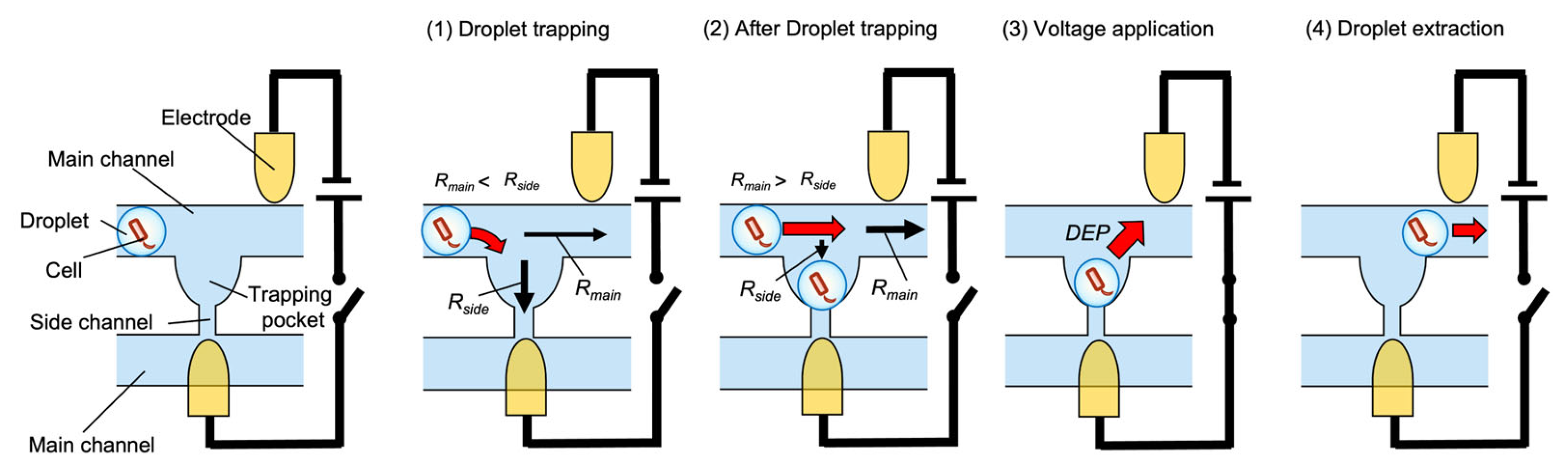
2.1. Operating Principle

The operating principle of the microdroplet manipulation system is depicted in Figure 1. We considered a simple system that uses hydrodynamics and DEP to selectively extract droplets.
A hydrodynamic mechanism is employed to trap microdroplets in the channel. Microdroplets are guided into the trapping pockets by making the flow resistance of the pocket and side channel (Rside) smaller than that of the main channel (Rmain). When a droplet is trapped in a pocket, the flow resistance increases and subsequent droplets pass through the main channel to the next pocket without being trapped in the same pocket section [12,13,18].
DEP is used to extract a microdroplet from a pocket. Microparticles such as microdroplets become polarized when an external electric field is applied, forming electric dipoles. If the applied electric field is nonuniform, different electric fields will be generated at the ends of the microparticle and the microparticle experiences a dielectrophoretic force. The dielectrophoretic force acting on a microparticle can be expressed by the following equation:
F DEP = 2 π ε m r 3 R e f CM | E | 2 ,
where εm is the permittivity of the surrounding liquid medium, r is the particle radius, Re indicates the real part of a complex function, fCM is the Clausius–Mossotti factor, and ∇|E|2 is the gradient of the square of the electric field. Here, fCM is given by
f CM = ε p * ε m * ε p * + 2 ε m * ,
where ε p * is the complex permittivity of the microparticle and ε m * is the complex permittivity of the surrounding liquid medium. When fCM > 0, the microparticle is attracted toward the stronger electric field, which is referred to as positive dielectrophoresis (P-DEP); conversely, when fCM < 0, the microparticle is attracted toward the weaker electric field, which is referred to as negative dielectrophoresis (N-DEP). When a DC electric field is applied [26], fCM is given by the following equation:
f CM = σ p σ m σ p + 2 σ m ,
where σp and σm are the electrical conductivities of the microparticle and surrounding liquid medium, respectively. In other words, the electrical conductivity of the materials determines the direction of the dielectrophoretic force. If the electrical conductivity of the microparticle is higher than that of the surrounding liquid medium, P-DEP occurs, and if the electrical conductivity of the microparticle is lower than that of the surrounding liquid medium, N-DEP occurs. In this work, σp > σm because an agarose solution (microdroplets) was used as the microparticles, and mineral oil, which is an electrical insulator, was used as the surrounding liquid medium (carrier). Therefore, the microparticles in the microchannel would be expected to undergo P-DEP. The device should be designed to concentrate the electric field outside of the trapping pockets.

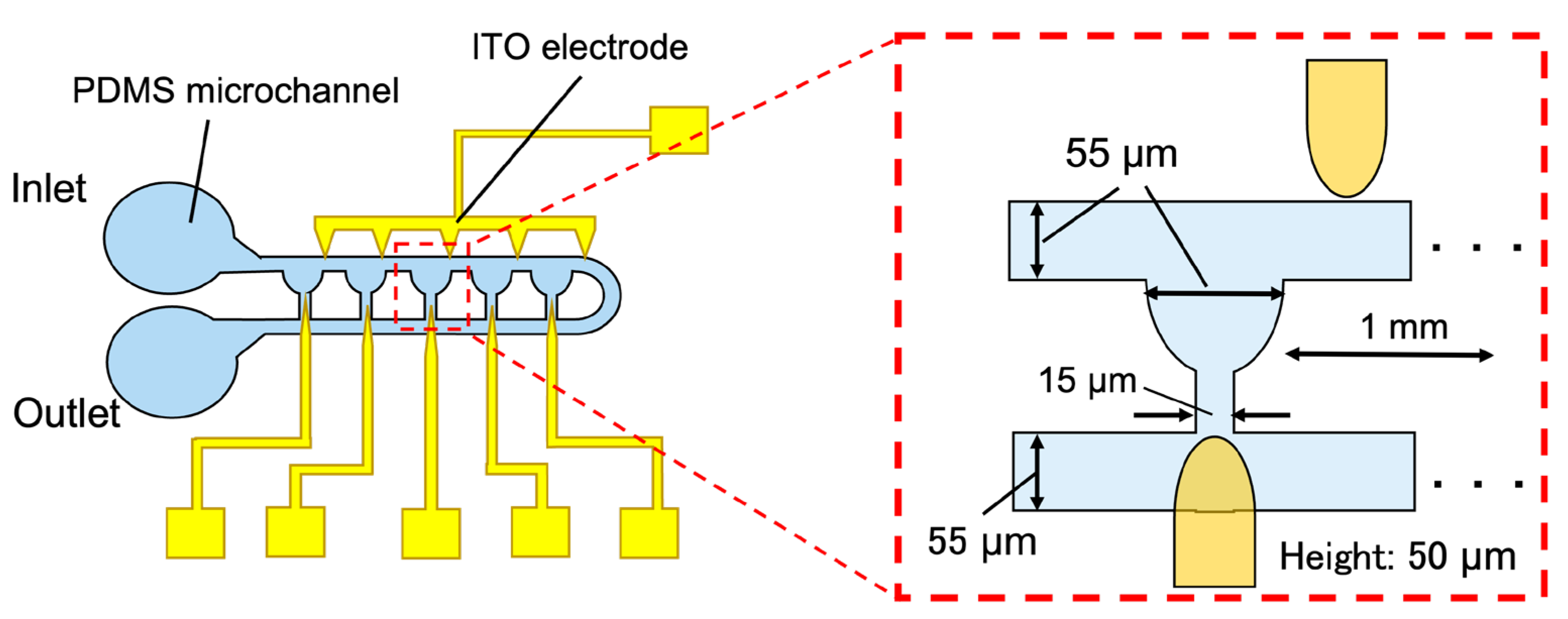
2.2. Device Design and Fabrication Process

Figure 2 presents the device design and dimensions. The device consisted of a main channel, five droplet-trapping pockets with side channels, and electrodes on a glass substrate. As described in Section 2.1, the device was designed such that droplets would be trapped in the pockets due to the difference in flow resistance between the main channel and the pocket structure. The upper electrodes were placed on the right side of the pockets to prevent extracted droplets from being trapped back into the pocket.
The channel height was 50 µm and the channel width and pocket diameter were 55 µm. Side channels were designed with 1 mm spacing and a width of 15 µm.
The microchannel was fabricated by soft lithography. A mold was made with an SU-8 photoresist (SU-8 3025). Polydimethylsiloxane (PDMS) and a curing agent were mixed in a ratio of 10:1 (w/w) and poured into the mold, thermally cured, and then removed from the mold to form the microchannel. Indium tin oxide (ITO) electrodes were fabricated by lithography and etching processes. The electrode design was patterned using AZ resist (AZ P4620) on a glass substrate coated with 700-nm-thick ITO, followed by wet etching of the excess ITO using 15% hydrochloric acid and removal of the resist using acetone and 2-propanol. Finally, the microchannel and ITO electrode on the substrate were aligned and bonded under a microscope (IX71, Olympus, Tokyo, Japan) after a plasma treatment (Aiplasma, Matsushita Electric Works, Forest Grove City, OR, USA). The bonded devices were then baked at 100 °C for 30 min to improve the bonding strength.

2.3. Reagent Preparation

Agarose solution was used for the microdroplets. Agarose and ultrapure water were mixed in a ratio of 1:99 (w/w) to obtain an agarose solution with a concentration of 1 wt%. Mineral oil was used as the carrier oil. Span 80 was added to the mineral oil at a concentration of 1 wt% as a surfactant.

2.4. Cell Preparation

E. coli cells were used as a model biological sample. The E. coli strain (DH 10B) used in this study harbors a transcriptional fusion of a promoter-less gfp gene fused to a trc promoter. We cultured the cells in Luria–Bertani (LB) broth (Difco) supplemented with 0.1 mM isopropyl-β-d-thiogalactopyranoside at 37 °C with shaking. To prepare E. coli cells for enclosure within the droplets, an aliquot (2 µL) of the glycerol stock of E. coli cells was inoculated into an LB medium (2 mL) and incubated at 37 °C for 15 h with shaking. The cell culture was diluted to an OD600 value of 0.03 with liquefied agarose gel.

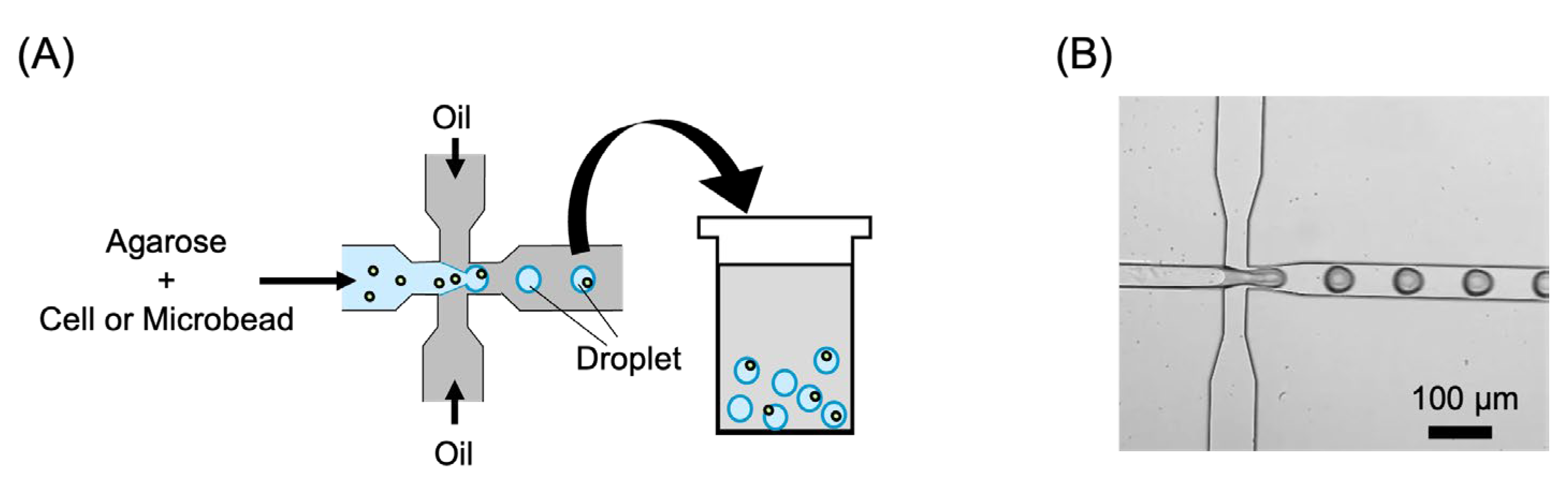
2.5. Agarose Droplet Preparation

Agarose droplets encapsulating E. coli or fluorescent microbeads were prepared shortly before their introduction into the microfluidic device. Agarose solutions containing E. coli or fluorescent microbeads and mineral oil were introduced into a microfluidic device for droplet generation. Figure 3 shows a schematic view and microscope image of droplet generation using the microfluidic device. The droplets were then collected and allowed to stand at 4 °C for 1 h to allow them to gel completely.

2.6. Experimental Setup

The agarose gel droplets and mineral oil were introduced into the device via syringes (1750 CX, Hamilton, Reno, NV, USA) driven by syringe pumps (Legato 100, KD Scientific, Holliston, MA, USA). A DC voltage/current source (6166, ADCMT) was used to apply a voltage between the electrode pairs. In this case, the anode and cathode were connected to the upstream and downstream electrodes, respectively. The experimental results were observed using a microscope (IX71, Olympus, Tokyo, Japan) and a high-speed camera (FASTCAM Mini AX, Photron, Tokyo, Japan).

3. Results and Discussion

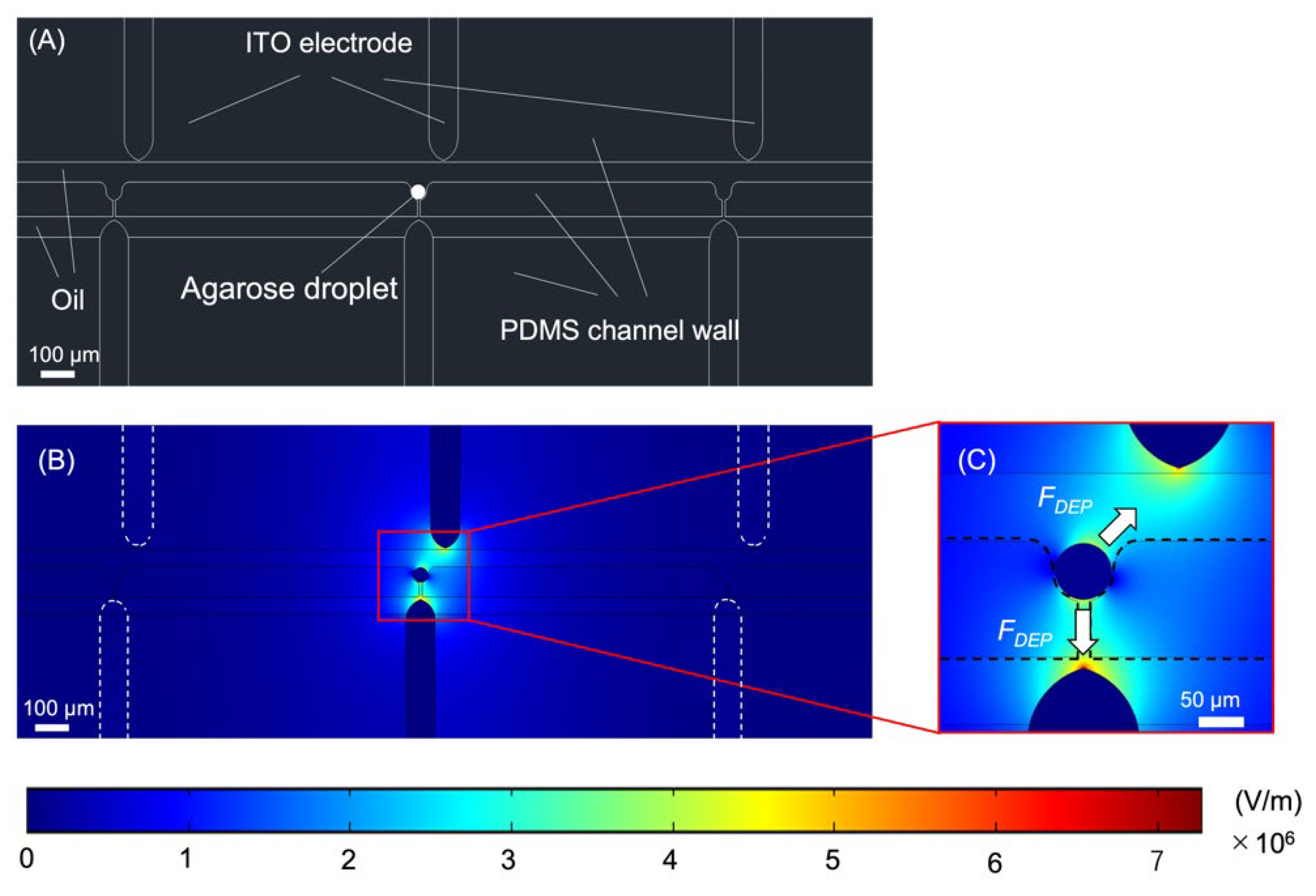
3.1. Finite Element Simulations

Accurate droplet extraction requires an optimized electric field distribution. Finite element simulations were performed using COMSOL Multiphysics 5.4 to investigate the electric field distribution in the device.
A model featuring three pockets and three electrode pairs was used for the simulations. The relative permittivity was set to 78 for the microdroplet (Agarose droplet), 2.5 for the liquid medium surrounding the droplet (Oil), 2.75 for the channel wall (PDMS channel wall), and 1 for the electrode (ITO). The distribution of the electric field gradient in the channel was simulated with the electrostatics interface of the AC/DC module, and a DC voltage of 500 V was applied to the electrode pair at the center of the model. The mesh used was a physics-controlled mesh and the size was finer. Figure 4 presents the simulation results at time t, right when the voltage is applied. Only one electrode pair was activated at a time; consequently, the other trapping pockets were not exposed to the electric field (Figure 4B). This result indicated that DEP should occur only for the corresponding droplets when a voltage is applied. In addition, the electric field was strongest at the tip of the electrode pair through which the voltage was applied. Therefore, the dielectrophoretic force (FDEP) experienced by the droplet can be considered to occur in the direction shown in Figure 4C. Since the FDEP generated in the direction of the lower electrode is blocked by the trapping structure, the droplet can be expected to move in the direction of the upper electrode. The simulation results also indicate that droplets are exposed to an electric field, and there is a possibility that the cells within the droplets may be affected by the voltage. Several studies have reported that applied DEP can cause stress to cells [27,28]. Desai et al. [29] investigated the effects of DEP on NIH3T3 fibroblasts and reported increased stress on the cells with increasing field voltage and exposure time. Therefore, this study should investigate the effects of the extraction process on the cells within the droplet.

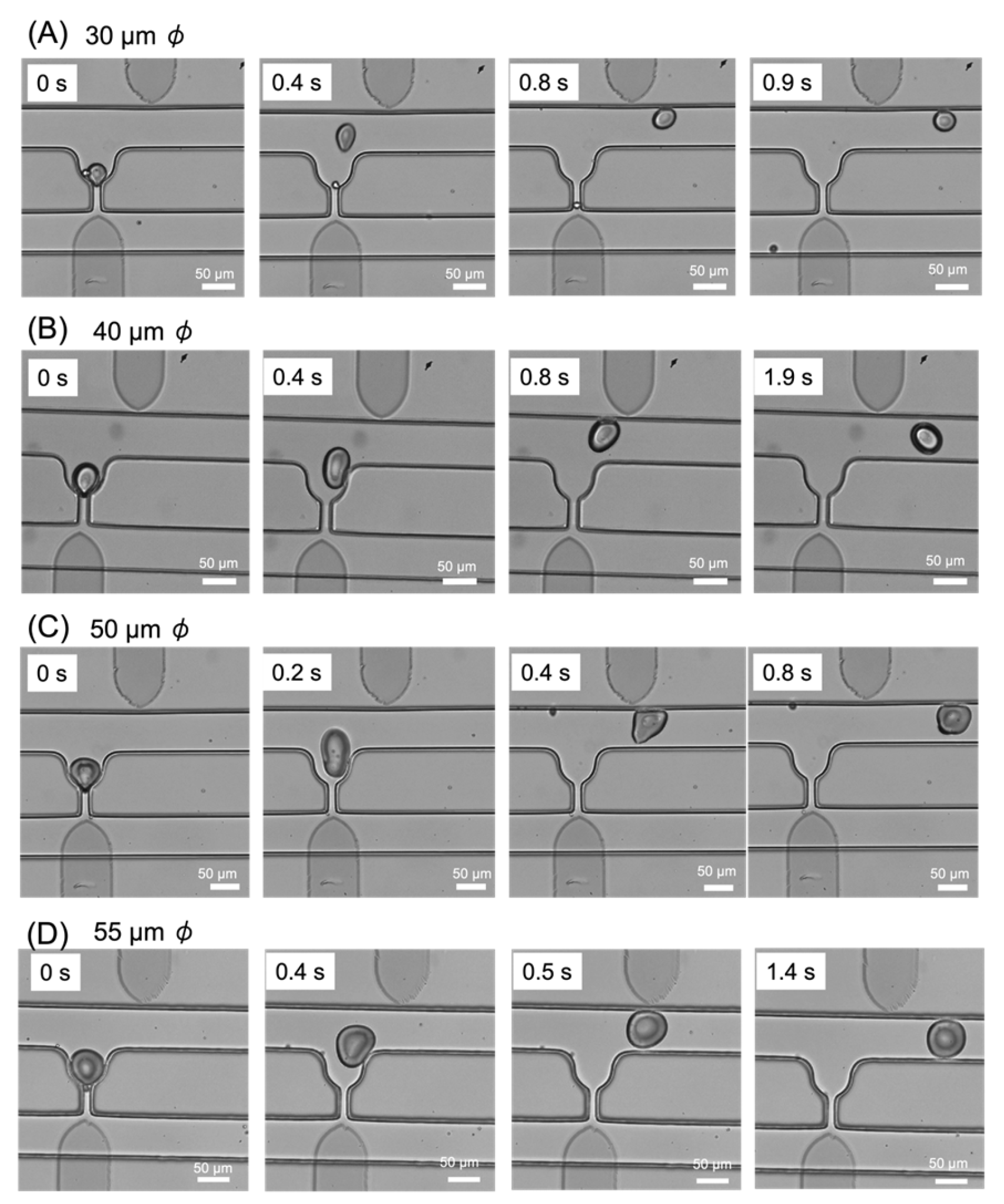
3.2. Droplet Trapping and Extraction

In this subsection, we discuss droplet trapping and extraction, which are the key aspects of this study. Agarose droplets and mineral oil were injected from the inlet at a flow rate of 0.2 μL/min. Figure 5 (Supplementary Materials, Video S1) shows the trapping and extraction of four droplets of different diameters ranging from 30 to 55 μm. After the trapping of the droplets, a voltage was applied to the electrodes to generate P-DEP between them. The voltage was applied continuously until the droplets had been extracted. The application of a voltage of 500 V to the electrodes for 400–800 ms caused the trapped droplets of all sizes (30–55 μm) to be extracted from the pocket as they were pulled toward the upper electrode. The results indicate that the generated dielectrophoretic force was sufficient to extract the droplets. Although successful extraction was confirmed at all voltages ranging from 500 V to 1 kV, the lowest applied voltage of 500 V was selected as the optimal value for cell experiments. A released droplet may become trapped again in an open trapping pocket further downstream. When this occurs, it is necessary to re-extract the droplet by applying a voltage to the electrode of the downstream pocket. These experimental results demonstrate that the fabricated device was capable of trapping and extracting droplets of various sizes.

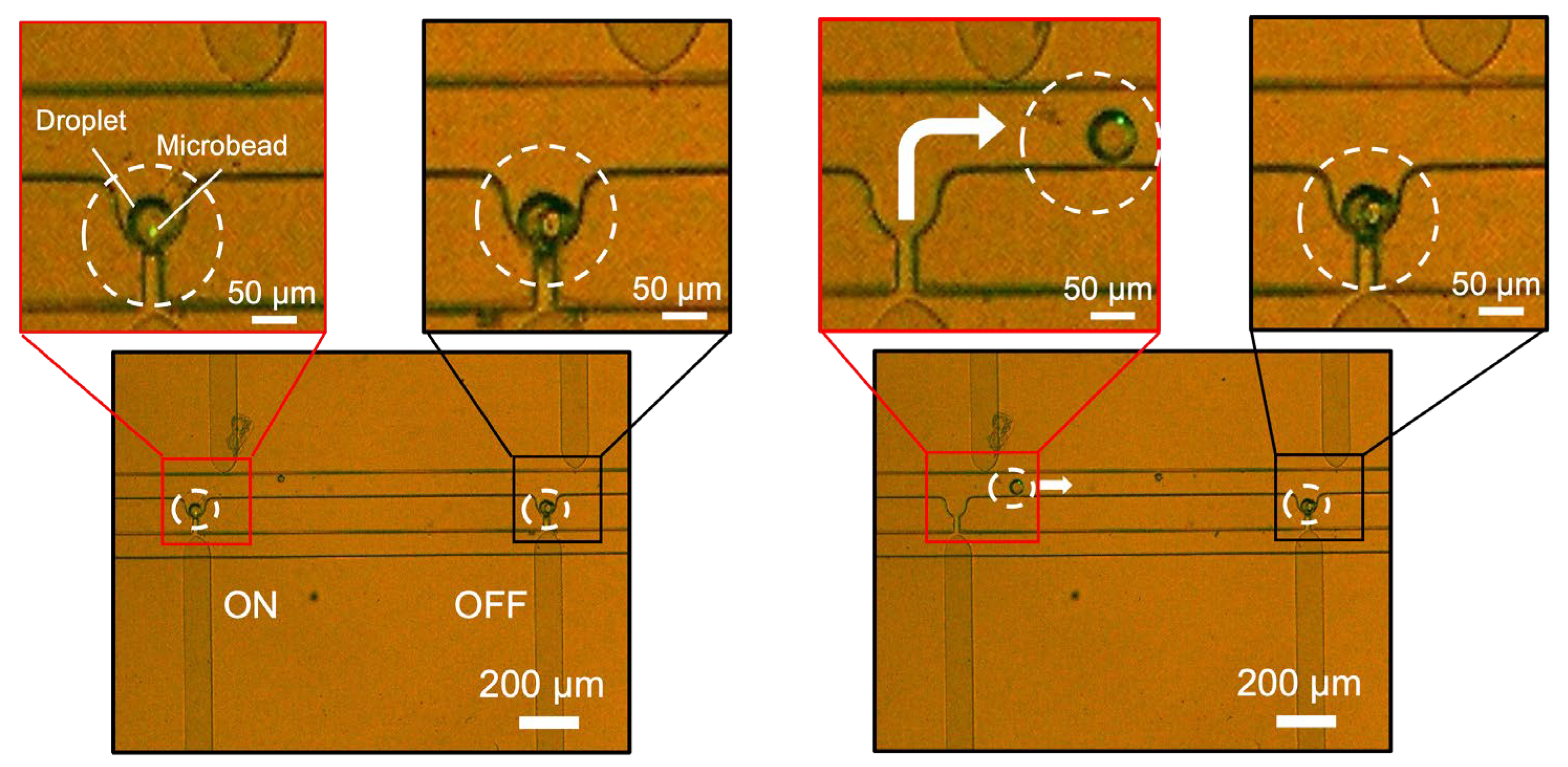
3.3. Selective Droplet Extraction

As a next step, we observed two pockets simultaneously to evaluate the capability of the device for selective droplet extraction. For this experiment, we used agarose droplets encapsulating fluorescent microbeads (3 μm diameter). Figure 6 (Supplementary Materials, Video S2) shows the obtained images. Agarose droplets encapsulating fluorescent microbeads and mineral oil were injected from the inlet at a flow rate of 0.2 μL/min to trap the droplets in the pockets. The trapped droplet on the left of the image contained a microbead, whereas the droplet on the right was empty. When 500 V were applied only to the pair of electrodes corresponding to the left pocket, only the droplet on the left side was extracted. These results suggest that P-DEP only occurred in the pockets between electrode pairs to which the voltage was applied, thus confirming the feasibility of selective droplet extraction.

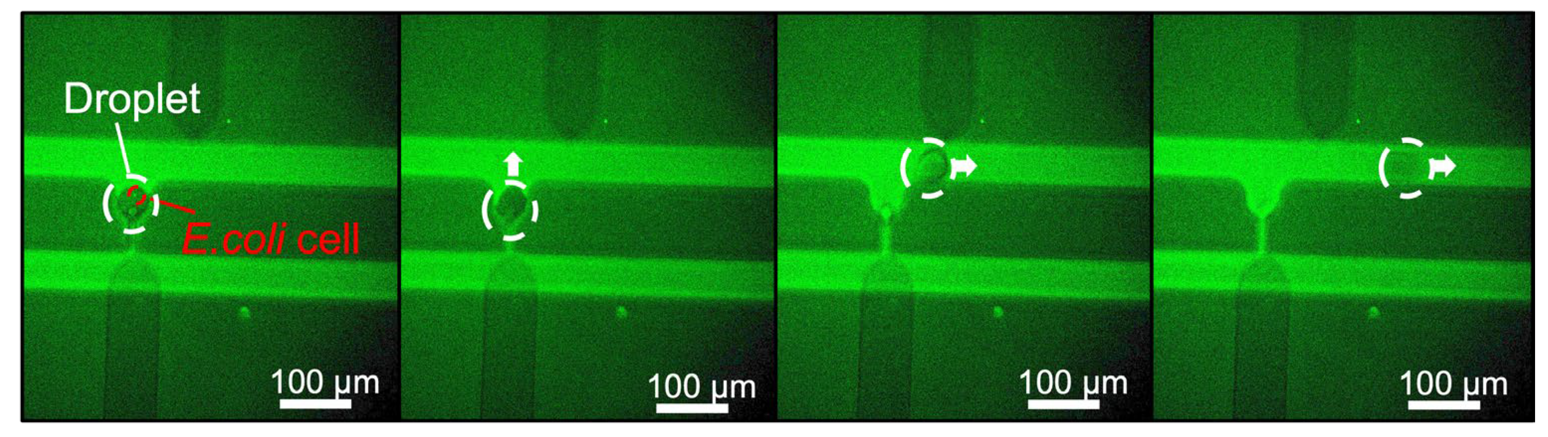
3.4. Application of the Device to Biological Samples

The ability to conduct reproducible experiments using cells was next examined as an important element for validating the biological utility of the device. Figure 7 (Supplementary Materials, Video S3) shows the trapping and extraction of agarose droplets encapsulating E. coli cells. Agarose droplets encapsulating E. coli cells and mineral oil were injected at a flow rate of 0.2 µL/min from the inlet and the droplets became trapped in the pockets. Upon applying a voltage of 500 V to the corresponding electrode pair, sufficient P-DEP was generated between the electrodes to extract the droplets. The results indicate that the fabricated device is capable of trapping and extracting droplets encapsulating bacteria and other biomolecules.

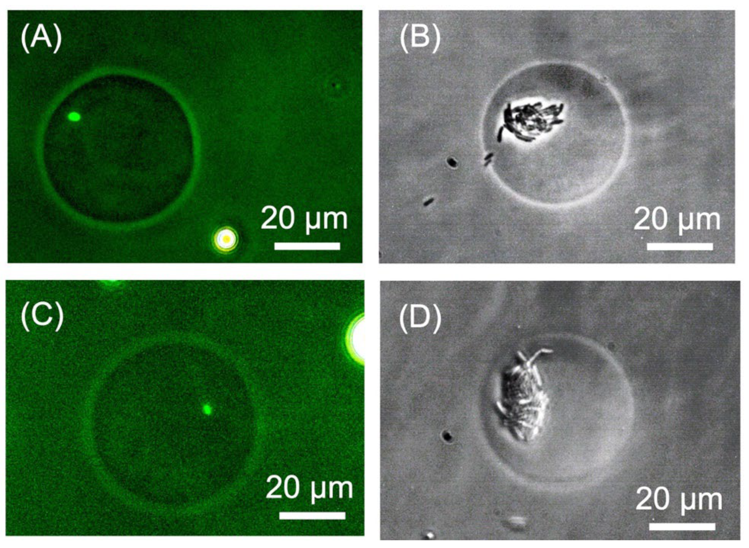
3.5. Evaluation of Damage to Biological Samples

To evaluate whether the extraction process damaged the E. coli cells in the droplets, the specific growth rates of the cells were compared between the droplets subject to an applied voltage (DEP droplets) and those not subject to an applied voltage (control droplets). The droplets were washed to remove oil and incubated in an LB medium at 20 °C. After a period of time, the number of E. coli cells in the droplets was counted under a microscope. The number of E. coli cells encapsulated in a droplet is determined stochastically according to a Poisson distribution, such that the number of cells in each droplet may vary [30]. Therefore, 15 droplets were randomly selected from the droplet population and the average number of cells was calculated. Table 1 shows the number of E. coli cells in the droplets immediately after washing and after 15 h of incubation. In addition, Figure 8 presents images of the DEP and control droplets. The number of E. coli cells in the control droplets increased from 0.9 before incubation to 17.8 after 15 h, while the number of E. coli cells in the DEP droplets increased from 1.3 before incubation to 21.8 after 15 h. Under constant culture conditions, the specific growth rate of bacteria can be expressed by the following formula [31]:
α t = ln n n 0 ,
where α is the specific growth rate, t is the incubation time, n is the number of bacteria at time t, and n 0 is the initial number of bacteria. The growth rate per hour was calculated to be 0.2 for the control droplets and 0.19 for the DEP droplets. The experiment was repeated three times to confirm the accuracy of the results. The growth rates for the second trial were as follows: control droplets were 0.21 and DEP droplets were 0.21. Similarly, the growth rates for the third trial were: control droplets were 0.22 and DEP droplets were 0.19. The standard deviation of the growth rate was calculated to be 0.006 for control droplets and 0.015 for DEP droplets. Additionally, the standard deviation of the growth rate per hour of the E. coli cells in the DEP droplets and the control droplets was calculated to be 0.01. These results indicate that the extraction process used in this study did not have a significant effect on the viability of E. coli.

4. Conclusions

In this study, we developed a simple new microfluidic device for droplet screening and low-damage selective extraction. For the purposes of the current demonstration, we fabricated a device containing five droplet-trapping pockets with electrode pairs positioned appropriately above and below each trapping pocket to generate a dielectrophoretic force. Experiments involving agarose droplets demonstrated that the device was capable of droplet trapping and selective extraction. Comparative experiments with droplets encapsulating E. coli cells confirmed that the extraction process had no significant effect on cell viability. Therefore, we believe that the results of this study will contribute to further progress in droplet-based single-cell analysis.

Supplementary Materials

The following supporting information can be downloaded at: https://www.mdpi.com/article/10.3390/mi14030706/s1: Video S1: droplet trapping and extraction. Video S2: selective extraction of target droplets. Video S3: trapping and extraction of agarose droplets encapsulating E. coli.

Author Contributions

Conceptualization, S.S. (Seito Shijo) and D.T.; methodology, S.S. (Seito Shijo); validation, S.S. (Seito Shijo); formal analysis, S.S. (Seito Shijo) and J.-i.I.; investigation, S.S. (Seito Shijo); writing—original draft preparation, S.S. (Seito Shijo); writing—review and editing, D.T., S.S. (Shuichi Shoji), J.-i.I., H.T. and M.K.; resources, D.T., J.-i.I., H.T. and S.S. (Shuichi Shoji); visualization, S.S. (Seito Shijo); supervision, S.S. (Shuichi Shoji); funding acquisition, S.S. (Shuichi Shoji), J.-i.I., H.T.; project administration, T.S. All authors have read and agreed to the published version of the manuscript.

Funding

This work was supported by the Japan Ministry of Education, Culture, Sports, Science and Technology (MEXT), a Grant-in-Aid for Scientific Basic Research (A) (No. 20H00336), the MEXT ARIM Japan (Advanced Research Infrastructure for Materials and Nanotechnology in Japan) of Waseda University, a Grant-in-Aid for Early-Career Scientists (No. 22K15152), AMED under Grant Number JP22gm1610004 and JST, ACT-X Grant Number JPMJAX21KA, Japan.

Institutional Review Board Statement

Not applicable.

Informed Consent Statement

Not applicable.

Data Availability Statement

The data presented in this study are available in (Supplementary Materials: Videos S1–S3).

Acknowledgments

The authors thank MEXT ARIM Japan of Waseda University and the Medical Mycology Research Center of Chiba University.

Conflicts of Interest

The authors declare no conflict of interest.

References

  1. Skelley, A.M.; Kirak, O.; Suh, H.; Jaenisch, R.; Voldman, J. Microfluidic control of cell pairing and fusion. Nat. Methods 2009, 6, 147–152. [Google Scholar] [CrossRef] [PubMed]
  2. Park, M.C.; Hur, J.Y.; Cho, H.S.; Park, S.; Suh, K.Y. High-throughput single-cell quantification using simple microwell-based cell docking and programmable time-course live-cell imaging. Lab Chip 2011, 11, 79–86. [Google Scholar] [CrossRef] [PubMed]
  3. Vriens, K.; Kumar, P.T.; Struyfs, C.; Cools, T.L.; Spincemaille, P.; Kokalj, T.; Sampaio-Marques, B.; Ludovico, P.; Lammertyn, J.; Cammue, B.P.; et al. Increasing the fungicidal action of Amphotericin B by inhibiting the nitric oxide-dependent tolerance pathway. Oxid. Med. Cell. Longev. 2017, 2017, 4064628. [Google Scholar] [CrossRef] [PubMed] [Green Version]
  4. Breukers, J.; Horta, S.; Struyfs, C.; Spasic, D.; Feys, H.B.; Geukens, N.; Thevissen, K.; Cammue, B.P.; Vanhoorelbeke, K.; Lammertyn, J. Tuning the surface interactions between single cells and an OSTE+ Microwell array for enhanced single cell manipulation. ACS Appl. Mater. Interfaces 2021, 13, 2316–2326. [Google Scholar] [CrossRef] [PubMed]
  5. Park, S.; Lee, J.Y.; Hong, S.; Dimov, I.K.; Li, K.; Wu, A.M.; Mumenthaler, S.; Mallick, P.; Lee, L.P. Concurrent transcript and protein quantification in a massive single cell array enables population-wide observation of oncogene escape. Biophys. J. 2013, 104, 686a. [Google Scholar] [CrossRef] [Green Version]
  6. Rettig, J.R.; Folch, A. Large-scale single-cell trapping and imaging using microwell arrays. Anal. Chem. 2005, 77, 5628–5634. [Google Scholar] [CrossRef]
  7. Yeo, T.; Tan, S.J.; Lim, C.L.; Lau, D.P.X.; Chua, Y.W.; Krisna, S.S.; Lim, C.T. Microfluidic enrichment for the single cell analysis of circulating tumor cells. Sci. Rep. 2016, 6, 22076. [Google Scholar] [CrossRef] [Green Version]
  8. Sun, X.; Li, B.; Li, W.; Ren, X.; Su, N.; Li, R.; Li, J.; Huang, Q. A resistance-based Microfluidic chip for deterministic single cell trapping followed by immunofluorescence staining. Micromachines 2022, 13, 1272. [Google Scholar] [CrossRef]
  9. Mondal, P.P.; Baro, N.; Singh, A.; Joshi, P.; Basumatary, J. Lightsheet optical tweezer (LOT) for optical manipulation of microscopic particles and live cells. Sci. Rep. 2022, 12, 10229. [Google Scholar] [CrossRef]
  10. Winters, A.; McFadden, K.; Bergen, J.; Landas, J.; Berry, K.A.; Gonzalez, A.; Salimi-Moosavi, H.; Murawsky, C.M.; Tagari, P.; King, C.T. Rapid single B cell antibody discovery using nanopens and structured light. MAbs 2019, 11, 1025–1035. [Google Scholar] [CrossRef] [Green Version]
  11. Kim, S.H.; Yamamoto, T.; Fourmy, D.; Fujii, T. Electroactive Microwell arrays for highly efficient single-cell trapping and analysis. Small 2011, 7, 3239–3247. [Google Scholar] [CrossRef]
  12. Lv, D.; Zhang, X.; Xu, M.; Cao, W.; Liu, X.; Deng, J.; Yang, J.; Hu, N. Trapping and releasing of single microparticles and cells in a microfluidic chip. Electrophoresis 2022, 43, 2165–2174. [Google Scholar] [CrossRef]
  13. Zhu, Z.; Frey, O.; Ottoz, D.S.; Rudolf, F.; Hierlemann, A. Microfluidic single-cell cultivation chip with controllable immobilization and selective release of yeast cells. Lab Chip 2012, 12, 906–915. [Google Scholar] [CrossRef] [Green Version]
  14. Kim, H.S.; Devarenne, T.P.; Han, A. A high-throughput microfluidic single-cell screening platform capable of selective cell extraction. Lab Chip 2015, 15, 2467–2475. [Google Scholar] [CrossRef]
  15. Xie, R.; Liu, Y.; Wang, S.; Shi, X.; Zhao, Z.; Liu, L.; Liu, Y.; Li, Z. Combinatorial perturbation sequencing on single cells using microwell-based droplet random pairing. Biosens. Bioelectron. 2023, 220, 114913. [Google Scholar] [CrossRef]
  16. Zheng, G.; Gu, F.; Cui, Y.; Lu, L.; Hu, X.; Wang, L.; Wang, Y. A microfluidic droplet array demonstrating high-throughput screening in individual lipid-producing microalgae. Anal. Chim. Acta 2022, 1227, 340322. [Google Scholar] [CrossRef]
  17. Khorshidi, M.A.; Rajeswari, P.K.; Wählby, C.; Joensson, H.N.; Andersson Svahn, H. Automated analysis of dynamic behavior of single cells in picoliter droplets. Lab Chip 2014, 14, 931. [Google Scholar] [CrossRef]
  18. Tan, W.; Takeuchi, S. Dynamic microarray system with gentle retrieval mechanism for cell-encapsulating hydrogel beads. Lab Chip 2008, 8, 259–266. [Google Scholar] [CrossRef]
  19. Toprakcioglu, Z.; Knowles, T.P. Sequential storage and release of microdroplets. Microsyst. Nanoeng. 2021, 7, 76. [Google Scholar] [CrossRef]
  20. Caen, O.; Schütz, S.; Jammalamadaka, M.S.; Vrignon, J.; Nizard, P.; Schneider, T.M.; Baret, J.; Taly, V. High-throughput multiplexed fluorescence-activated droplet sorting. Microsyst. Nanoeng. 2018, 4, 33. [Google Scholar] [CrossRef] [Green Version]
  21. Ali, M.; Park, J. Ultrasonic surface acoustic wave-assisted separation of microscale droplets with varying acoustic impedance. Ultrason. Sonochem. 2023, 93, 106305. [Google Scholar] [CrossRef] [PubMed]
  22. Agresti, J.J.; Antipov, E.; Abate, A.R.; Ahn, K.; Rowat, A.C.; Baret, J.; Marquez, M.; Klibanov, A.M.; Griffiths, A.D.; Weitz, D.A. Ultrahigh-throughput screening in drop-based microfluidics for directed evolution. Proc. Natl. Acad. Sci. USA 2010, 107, 4004–4009. [Google Scholar] [CrossRef] [PubMed] [Green Version]
  23. Schütz, S.S.; Beneyton, T.; Baret, J.; Schneider, T.M. Rational design of a high-throughput droplet sorter. Lab Chip 2019, 19, 2220–2232. [Google Scholar] [CrossRef] [PubMed] [Green Version]
  24. Isozaki, A.; Nakagawa, Y.; Loo, M.H.; Shibata, Y.; Tanaka, N.; Setyaningrum, D.L.; Park, J.; Shirasaki, Y.; Mikami, H.; Huang, D.; et al. Sequentially addressable dielectrophoretic array for high-throughput sorting of large-volume biological compartments. Sci. Adv. 2020, 6, eaba6712. [Google Scholar] [CrossRef]
  25. Jiang, T.; Jia, Y.; Sun, H.; Deng, X.; Tang, D.; Ren, Y. Dielectrophoresis response of water-in-Oil-in-water double emulsion droplets with singular or dual cores. Micromachines 2020, 11, 1121. [Google Scholar] [CrossRef]
  26. Li, D. DC-Dielectrophoresis in Microfluidic Chips. In Electrokinetic Microfluidics and Nanofluidics; Springer: Berlin/Heidelberg, Germany, 2022; pp. 77–106. [Google Scholar]
  27. Doornaert, B.; Leblond, V.; Galiacy, S.; Gras, G.; Planus, E.; Laurent, V.; Isabey, D.; Lafuma, C. Negative impact of DEP exposure on human airway epithelial cell adhesion, stiffness, and repair. Am. J. Physiol. Lung Cell. Mol. Physiol. 2003, 284, L119–L132. [Google Scholar] [CrossRef]
  28. Lu, J.; Barrios, C.A.; Dickson, A.R.; Nourse, J.L.; Lee, A.P.; Flanagan, L.A. Advancing practical usage of microtechnology: A study of the functional consequences of dielectrophoresis on neural stem cells. Integr. Biol. 2012, 4, 1223–1236. [Google Scholar] [CrossRef] [Green Version]
  29. Desai, S.P.; Voldman, J. Cell-based sensors for quantifying the physiological impact of microsystems. Integr. Biol. 2011, 3, 48–56. [Google Scholar] [CrossRef] [Green Version]
  30. Mazutis, L.; Araghi, A.F.; Miller, O.J.; Baret, J.; Frenz, L.; Janoshazi, A.; Taly, V.; Miller, B.J.; Hutchison, J.B.; Link, D.; et al. Droplet-based Microfluidic systems for high-throughput single DNA molecule isothermal amplification and analysis. Anal. Chem. 2009, 81, 4813–4821. [Google Scholar] [CrossRef]
  31. Novick, A.; Szilard, L. Experiments with the chemostat on spontaneous mutations of bacteria. Proc. Natl. Acad. Sci. USA 1950, 36, 708–719. [Google Scholar] [CrossRef] [Green Version]
Figure 1. Operating principle of the microdroplet manipulation system.
Micromachines 14 00706 g001
Figure 2. Schematic view and dimensions of the device.
Micromachines 14 00706 g002
Figure 3. Droplet generation using the microfluidic device. (A) Schematic view. (B) Microscope image.
Micromachines 14 00706 g003
Figure 4. Simulation results for the electric field distribution. (A) Schematic view of the model used for the simulation. (B) Electric field distribution throughout the model. (C) Electric field distribution around the central trapping pocket and the direction of FDEP generation.
Micromachines 14 00706 g004
Figure 5. Images of droplet trapping and extraction. (A) 30 μm, (B) 40 μm, (C) 50 μm, and (D) 55 μm.
Micromachines 14 00706 g005
Figure 6. Images of the selective extraction of target droplets. Voltage was applied to the left electrode pair only.
Micromachines 14 00706 g006
Figure 7. Trapping and extraction of agarose droplets encapsulating E. coli.
Micromachines 14 00706 g007
Figure 8. Photomicrographs of agarose droplets encapsulating E. coli cells. (A) Control droplet after 0 h of incubation, (B) Control droplet after 15 h of incubation, (C) DEP droplet after 0 h of incubation, and (D) DEP droplet after 15 h of incubation.
Micromachines 14 00706 g008
Table 1. Number of E. coli cells in agarose droplets.
TrialIncubation Time (h)Control DropletsDEP Droplets
1st00.91.3
1517.821.8
2nd00.80.9
1518.425.6
3rd01.01.1
1523.223.9
Disclaimer/Publisher’s Note: The statements, opinions and data contained in all publications are solely those of the individual author(s) and contributor(s) and not of MDPI and/or the editor(s). MDPI and/or the editor(s) disclaim responsibility for any injury to people or property resulting from any ideas, methods, instructions or products referred to in the content.

