The adhesion work can characterize the bonding strength of the interface structure. The greater the adhesion work, the stronger the interface bonding property and the more stable the interface structure. Furthermore, the charge-density difference and the density of states are analyzed by calculating the electronic structures of the model interface atoms, revealing the essence of interface bonding from the perspective of charge transfer and bonding mode.
3.1. Adhesion Work
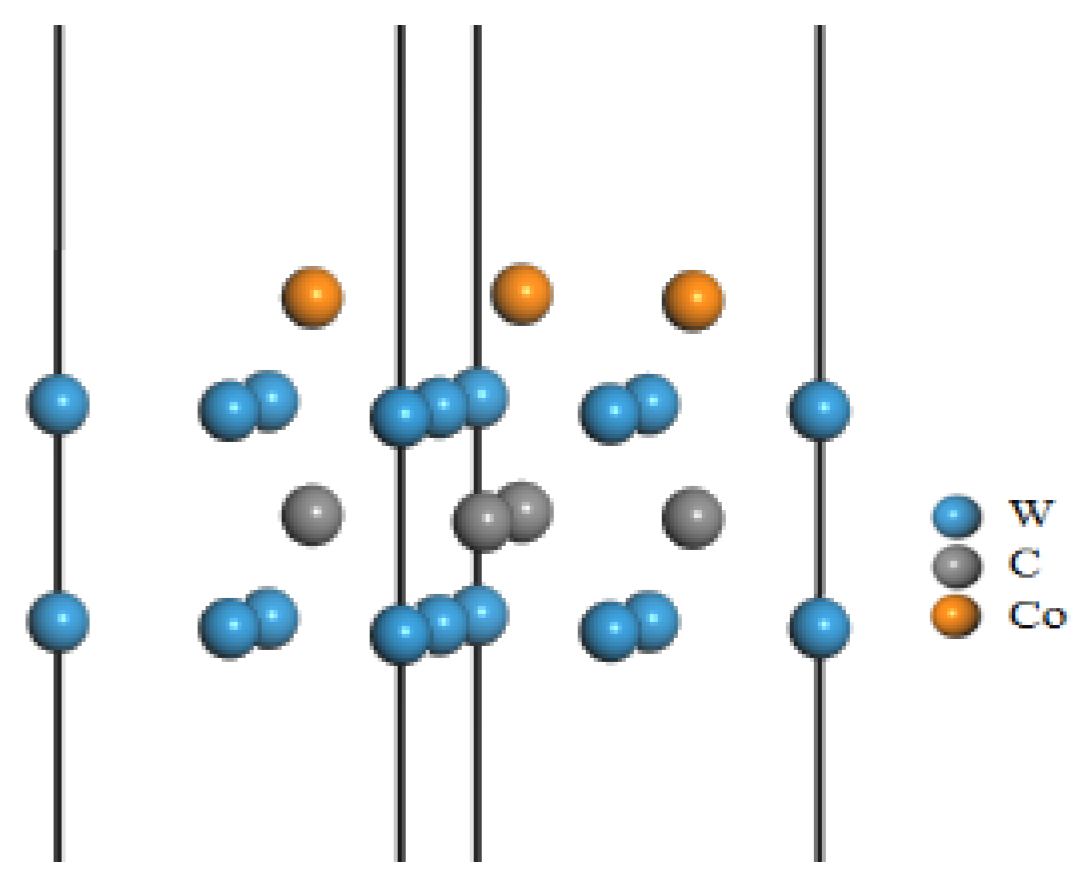
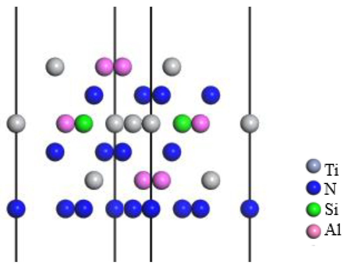
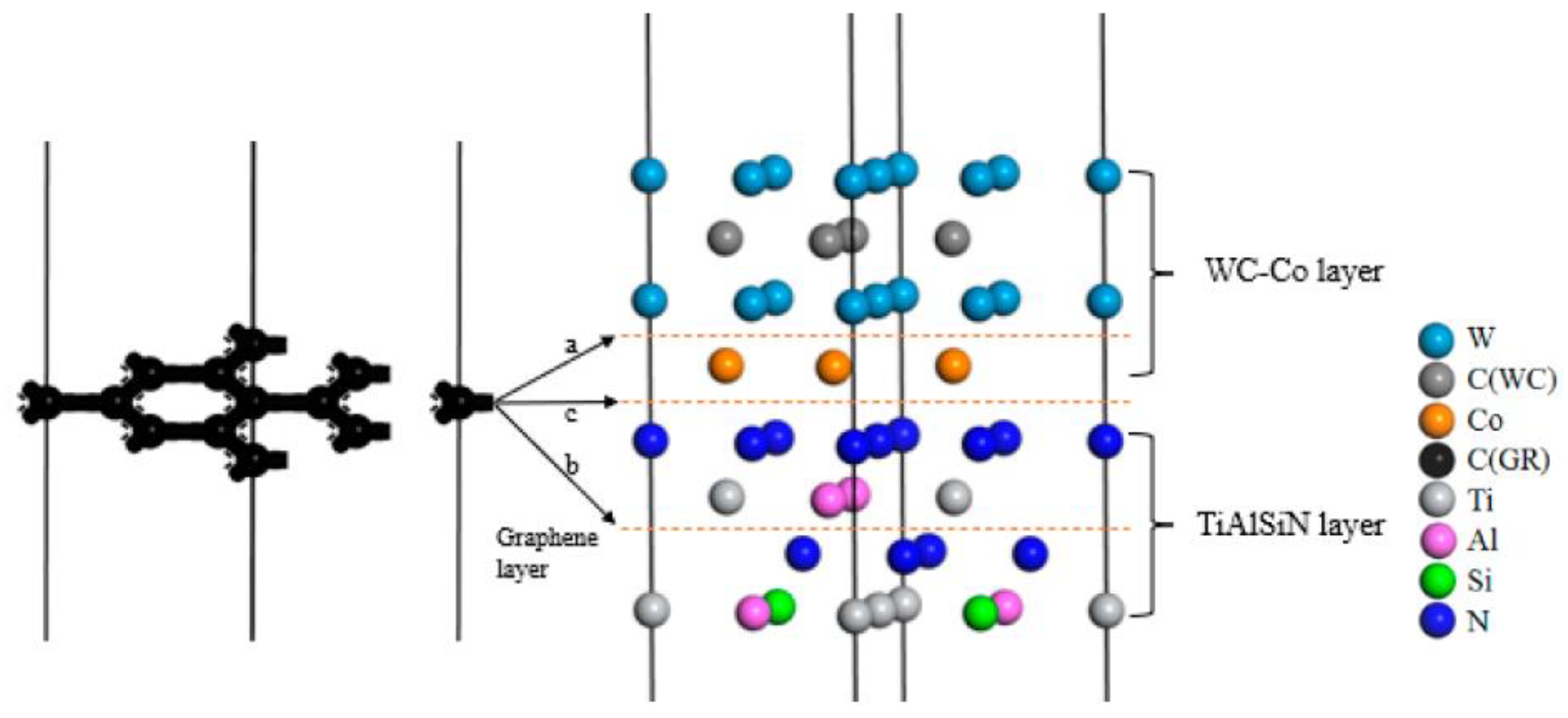
The interface
α/β adhesion work (Wad) calculation formula is [
46]:
where
Wad is the adhesion work, J/m
2;
Eα is the total energy of surface
α, eV;
Eβ is the total energy of surface
β, eV;
Eα/β is the total energy of the interface system, eV; and the total interface area is given by
A, Å
2.
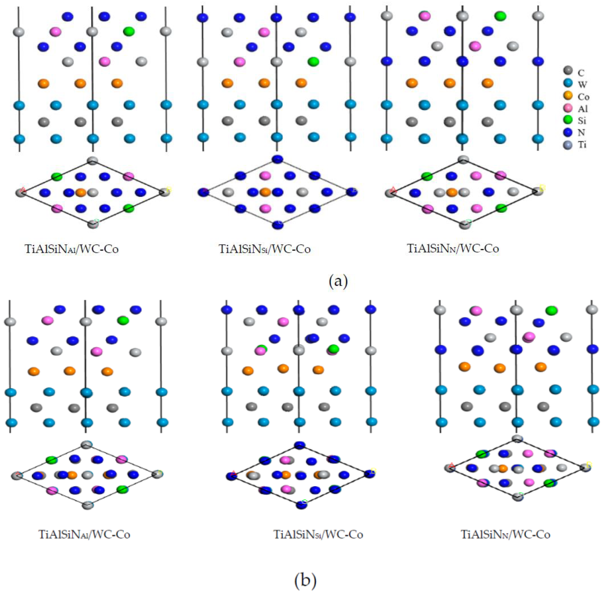
The calculated interface adhesion works of matrix doped with intrinsic graphene are shown in
Table 2. When the matrix is doped with the main surface of intrinsic graphene, the interface adhesion work of TiAlSiN
Si/WC/msGR/Co is larger than that of TiAlSiN
Si/WC-Co without graphene doping, and the interface adhesion work of TiAlSiN
N/WC/msGR/Co is larger than that of TiAlSiN
N/WC-Co, which indicates that the combination of the matrix and the main surface of intrinsic graphene improves the interface bonding property of TiAlSiN/WC-Co. When the matrix is doped with the graphene boundary, the adhesion works of TiAlSiN
Si/Co interface and TiAlSiN
N/Co interface are less than those without doping, which indicates that the combination of matrix and graphene boundary reduces the interface bonding property of TiAlSiN/WC-Co.
The calculated interface adhesion works of matrix doped with defective graphene are shown in
Table 3. When the matrix is doped with svGR and tdGR, the adhesion works of TiAlSiN
Si/Co and TiAlSiN
N/Co are less than those without doping, respectively, which indicates that the combination of matrix and defective graphene reduces the interface bonding property of TiAlSiN/WC-Co.
By comparing adhesion works of Si and N terminal models of matrix doped with graphene, given in
Table 2 and
Table 3, it can be concluded that when the matrix is doped with graphene, doping msGR can increase interface adhesion works of Si and N terminal models. When matrix is doped with other forms of graphene, interface adhesion works of Si and N terminal models decrease in varying degrees, and adhesion works of Si terminal models clearly decrease. In the N terminal models, when matrix is doped with tdGR, the interface adhesion work is the least and the interface bonding property is the worst. In the Si terminal models, the interface adhesion work is the least and the interface bonding property is the worst when matrix is doped with acGR, and there is a situation that the adhesion work of the Si terminal model is less than that of the N terminal model at this time, and adhesion works of Si terminal models with the matrix doped with other forms of graphene are larger than those of N terminal models. It can be seen that the interface bonding property decreases most obviously when the Si terminal model is doped with acGR.
The calculated interface adhesion works of coating doped with intrinsic graphene are shown in
Table 4. When the coating is doped with the main surface of intrinsic graphene, the adhesion work of the TiAlSiN
Si/Co interface of TiAlSiN/msGR/TiAlSiN
Si/WC-Co is less than that of the TiAlSiN
Si/Co interface of TiAlSiN
Si/WC-Co without graphene doping, and the interface bonding property of TiAlSiN/msGR/TiAlSiN
Si/WC-Co decreases.
The adhesion works of the TiAlSiNN/Co interface of TiAlSiN/msGR/TiAlSiNN/WC-Co are larger than that of the TiAlSiNN/Co interface of TiAlSiNN/WC-Co without graphene doping, and the interface bonding property of TiAlSiN/msGR/TiAlSiNN/WC-Co increases. The results indicate that the coating is doped with the main surface intrinsic graphene in the N terminal model, and the interface bonding property of TiAlSiN/msGR/TiAlSiNN/WC-Co increases. When the coating is doped with the graphene boundary, the adhesion works of TiAlSiNSi/Co and TiAlSiNN/Co are less than those without doping, which indicates that the combination of coating and graphene boundary reduces the interface bonding property of TiAlSiN/WC-Co.
The calculated interface adhesion works of coating doped with defective graphene are shown in
Table 5. The adhesion work results show that only when the coating in the N terminal model of TiAlSiN
N/WC-Co is doped with svGR, the adhesion work of each interface increases compared with that of TiAlSiN
N/WC-Co without doping, and the interface bonding property increases. When the coating is doped with svGR, in the Si terminal model of TiAlSiN
Si/WC-Co and different terminal models of doping tdGR, there are interfaces whose adhesion works decrease, and the interface bonding property decreases.
By comparing adhesion works of Si and N terminal models doped with graphene in coating, given in
Table 4 and
Table 5, it can be concluded that when coating is doped with graphene, the interface adhesion works of Si terminal models decrease in varying degrees, and the interface bonding property decreases. The interface adhesion work is the least and the interface bonding property is the worst when coating is doped with zzGR. In the N terminal models, when the coating is doped with msGR and svGR, the interface adhesion works increase in varying degrees, and the interface bonding property improves. However, the interface adhesion works decrease when coating is doped with acGR, zzGR, and tdGR, and the interface adhesion work is the least when the coating is doped with acGR, and the bonding property is the worst. Compared with the coating without graphene, when the coating is doped with graphene, the adhesion works of Si terminal models are less than those of N terminal models. It can be seen that the interface bonding property decreases most obviously when Si terminal models are doped with graphene.
The calculated interface adhesion works of the coating/matrix interface doped with intrinsic graphene are shown in
Table 6. It can be seen that when the coating/matrix interface is doped with the main surface of intrinsic graphene, the interface adhesion work of TiAlSiN
Si/msGR/WC-Co of the Si terminal model is less than that of the TiAlSiN
Si/WC-Co interface without doping graphene, and the interface bonding property of TiAlSiN
Si/msGR/WC-Co decreases. The interface adhesion work of TiAlSiN
N/msGR/WC-Co of the N terminal model is larger than that of the TiAlSiN
N/WC-Co interface, and the interface bonding property of TiAlSiN
N/msGR/WC-Co increases. When the coating/matrix interface is doped with the graphene boundary, in different terminal models, there are interfaces whose interface adhesion works are less than that of the TiAlSiN/WC-Co interface. It indicates that when the coating/matrix interface is doped with an intrinsic graphene boundary, the interface bonding property of TiAlSiN/WC-Co decreases.
The calculated interface adhesion works of the coating/matrix interface doped with defective graphene are shown in
Table 7. The adhesion work results show that only when the coating/matrix interface in TiAlSiN
N/WC-Co is doped with svGR does the adhesion work of each interface increase compared with that of TiAlSiN
N/WC-Co without doping, and the interface bonding property increases. In TiAlSiN
Si/svGR/WC-Co, TiAlSiN
Si/tdGR/WC-Co, and TiAlSiN
Si/tdGR/WC-Co, there are interfaces whose interface adhesion works decrease, and the interface bonding property decreases.
By comparing adhesion works of Si and N terminal models doped with graphene in coating/matrix interface, given in
Table 6 and
Table 7, it can be concluded that when the coating/matrix interface is doped with graphene, the interface adhesion works of Si terminal models decrease in varying degrees, and the interface bonding property decreases. The interface adhesion work is the least and the interface bonding property is the worst when the coating/matrix interface is doped with msGR. In the N terminal models, when the coating/matrix interface is doped with msGR and svGR, the interface adhesion works increase in varying degrees, and the interface bonding property improves, and the interface adhesion work is the largest when the coating/matrix interface is doped with msGR. However, the interface adhesion work decreases when the coating/matrix interface is doped with acGR, zzGR, and tdGR, and the interface adhesion work is the least when the coating/matrix interface is doped with acGR, and the bonding property is the worst. When the coating/matrix interface is doped with acGR, svGR, and tdGR, the adhesion work of the Si terminal model is larger than that of N terminal model. When the coating/matrix interface is doped with msGR and zzGR, there is a situation that the adhesion work of the Si terminal model is less than the N terminal model. It can be seen that the interface bonding property decreases most obviously when Si terminal models are doped with grapheme.
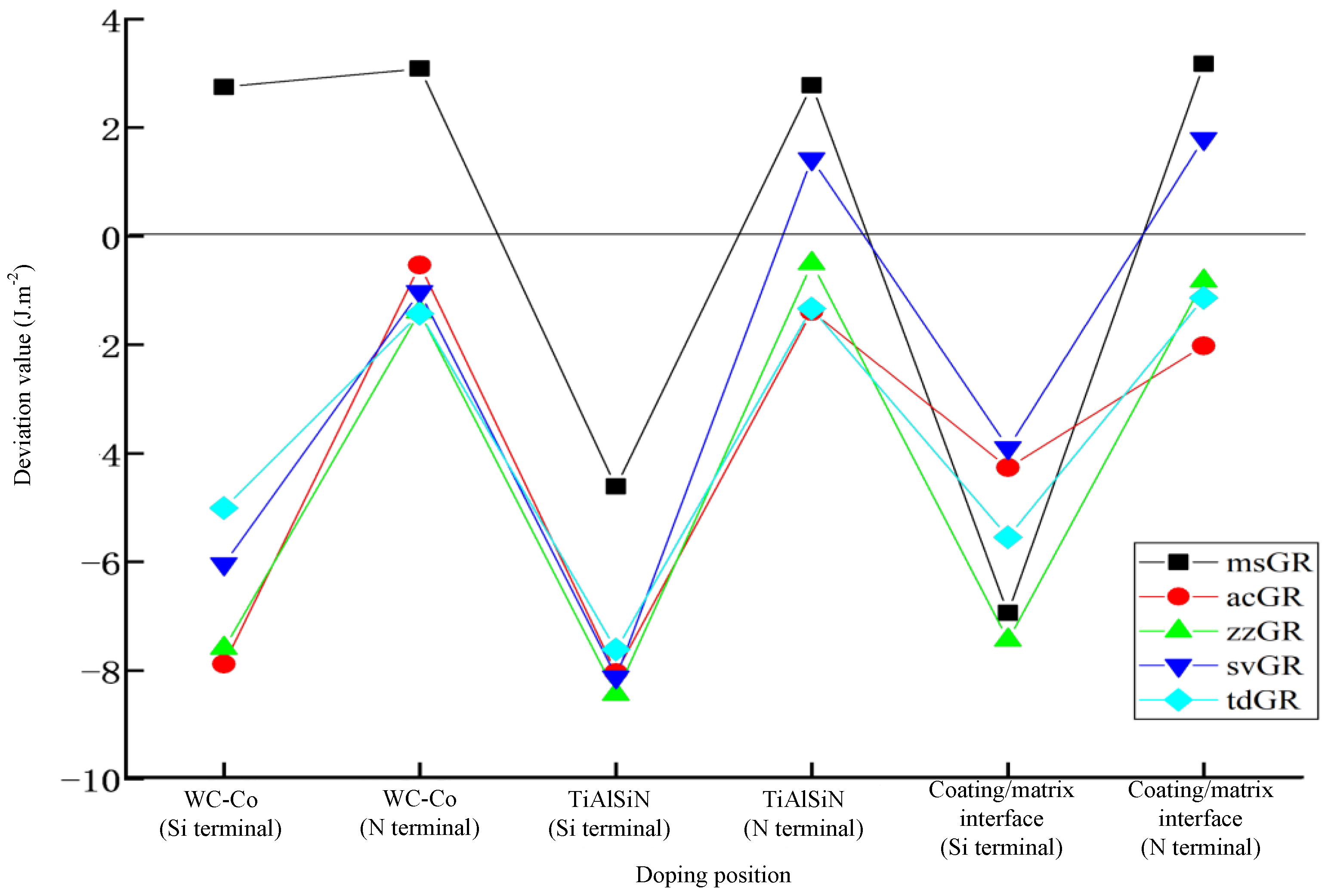
After calculation, the adhesion works of the graphene-doped TiAlSiN/WC-Co interface model were summarized, as shown in
Table 8. The influence of graphene doping on the interface bonding property of TiAlSiN/WC-Co is analyzed.
Figure 8 shows the deviation between the adhesion work of graphene-doped TiAlSiN/WC-Co and that of TiAlSiN/WC-Co without graphene doping. The results show that in the N terminal model, the differences between the adhesion work of TiAlSiN/WC-Co doped with graphene in WC-Co or TiAlSiN and that of TiAlSiN/WC-Co without graphene doping are small. In the Si terminal model, the differences between the adhesion work of TiAlSiN/WC-Co doped with graphene in WC-Co and that of TiAlSiN/WC-Co without graphene doping are significant.
It can be seen from
Table 8 that, from the doping position, when the matrix is doped with graphene, msGR improves the interface bonding properties of both Si and N terminal models, while other forms of graphene doping cannot improve their interface bonding property. When the coating is doped with graphene, msGR and svGR improve the interface bonding properties of TiAlSiN
N/WC-Co, while other forms of graphene doping cannot improve the interface bonding property of TiAlSiN/WC-Co. When the coating/matrix interface is doped with graphene, msGR and svGR improve the interface bonding properties of TiAlSiN
N/WC-Co, while other forms of graphene doping cannot improve the interface bonding property of TiAlSiN/WC-Co.
From the perspective of different forms of graphene doping, it is found that when msGR is doped into the matrix of Si terminal models, the interface bonding property of TiAlSiNSi/WC-Co increases; when msGR is doped into the matrix, coating, and the coating/matrix interface of N terminal models, the interface bonding property of TiAlSiNN/WC-Co increases, but acGR, zzGR, and tdGR cannot improve the interface bonding property of TiAlSiN/WC-Co.
3.2. Electronic Structure
(1) Charge-density difference
The charge-density distribution in atoms can be analyzed by the charge-density difference image. The charge-density difference of TiAlSiN
Si/WC-Co and TiAlSiN
N/WC-Co interface models is calculated, and the charge-density difference images are shown in
Figure 9,
Figure 10,
Figure 11,
Figure 12,
Figure 13 and
Figure 14. In the figures, the red, blue, and white areas indicate the decreased, increased, and approximately unchanged charge density, respectively.
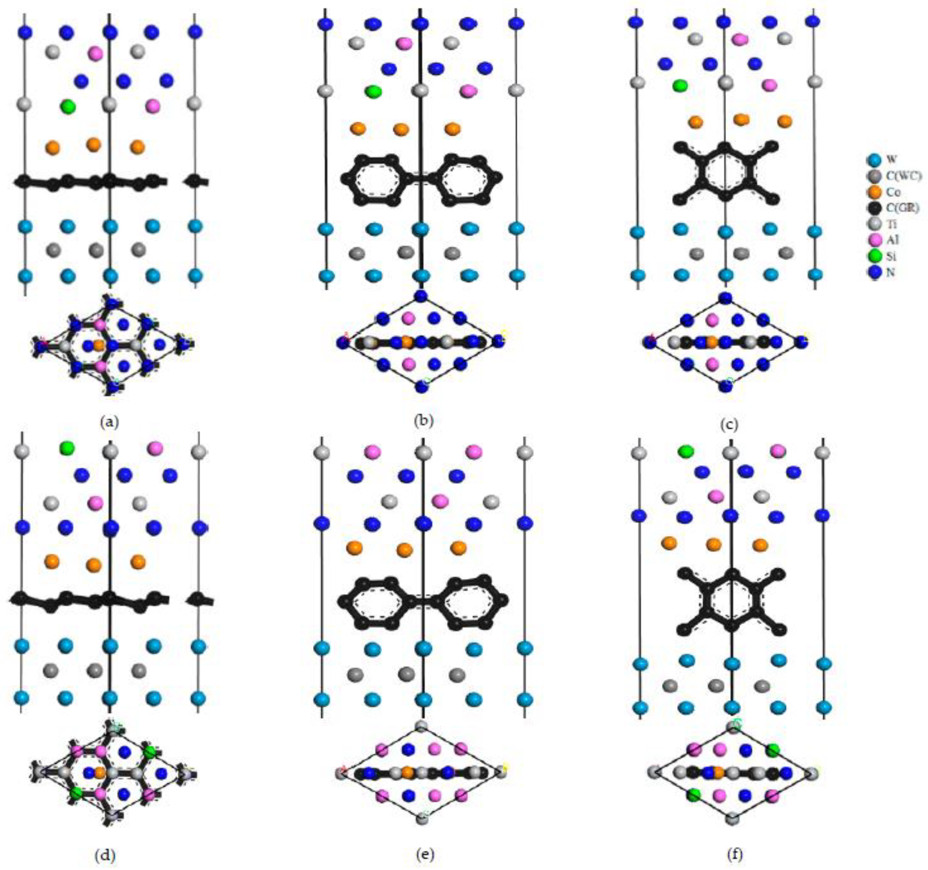
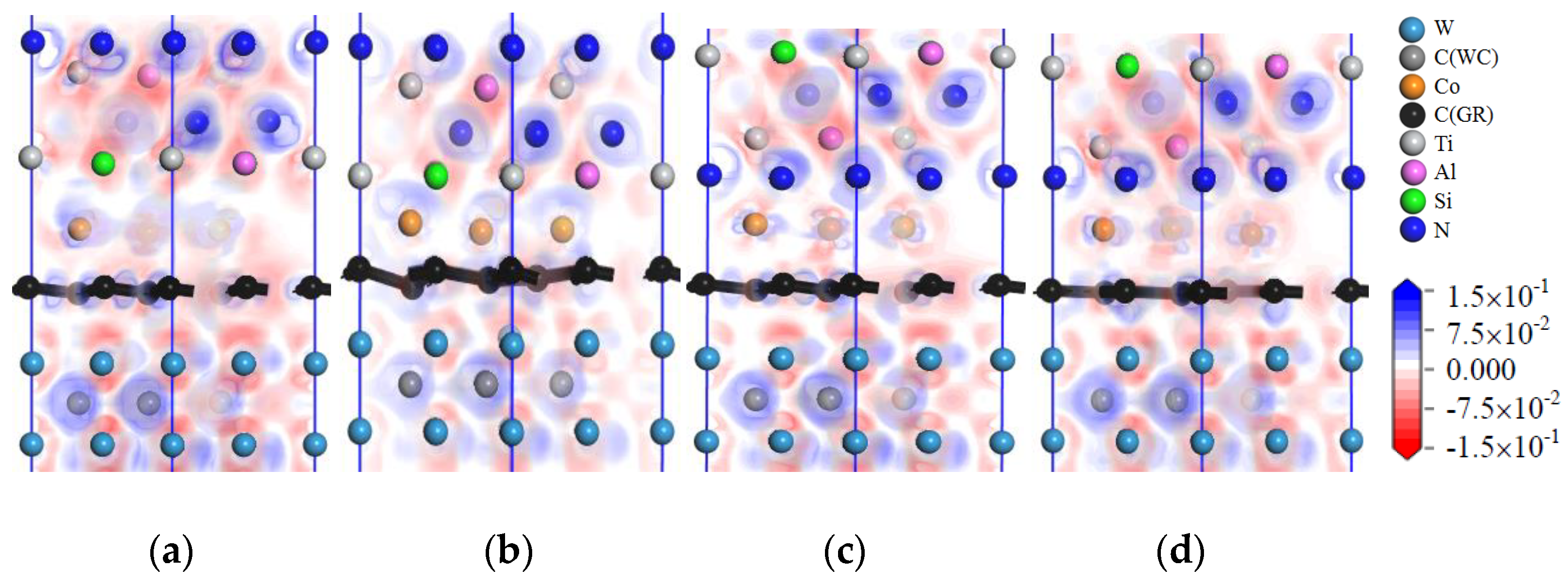
Figure 9 shows the charge-density difference images of the interface models with intrinsic graphene doping in the matrix. In
Figure 9a, at the TiAlSiN
Si/WC-Co interface, there is charge accumulation between Si atoms and Co atoms, that is, covalent bonds exist; when the matrix is doped with msGR, this introduces msGR/Co and /WC/msGR into the interfaces. As shown in
Figure 9b, there is obvious electron transfer between Si and Co atoms at the interface of TiAlSiN
Si/WC/msGR/Co, and the electron cloud near the Co atom moves toward the Si atom, which enhances the attraction of Si to the Co atom and forms a strong Si/Co covalent bond. As shown in
Figure 9e, the charge accumulation between N and Co atoms at the TiAlSiN
N/WC-Co interface indicates the existence of covalent bonds. As shown in
Figure 9f, at the interface of TiAlSiN
N/WC/msGR/Co, N atoms are in the electron-enriched state, while Co atoms are in the electron-absent state, and there is attraction between N and Co atoms. When the matrix is combined with msGR, the newly introduced interface is stable and the original interface is well combined. In the four interface models, in which the matrix is doped with the graphene boundary, as shown in
Figure 9c,d,g,h, there is a certain bonding force between C and Co and W atoms, while there is a charge gap between TiAlSiN and Co atoms, and the bonding force between atoms is weak, which leads to a decrease in the interface bonding property of TiAlSiN/WC-Co. When the matrix is doped with acGR, compared with the N terminal model, the Si terminal model has more charge blank areas at the interface, and the forces between Si atoms and Co and C atoms are small, and the interface bonding property decreases. The results are consistent with those shown in
Table 2 and
Table 3, that the adhesion work of the Si terminal model is less than that of the N terminal model.
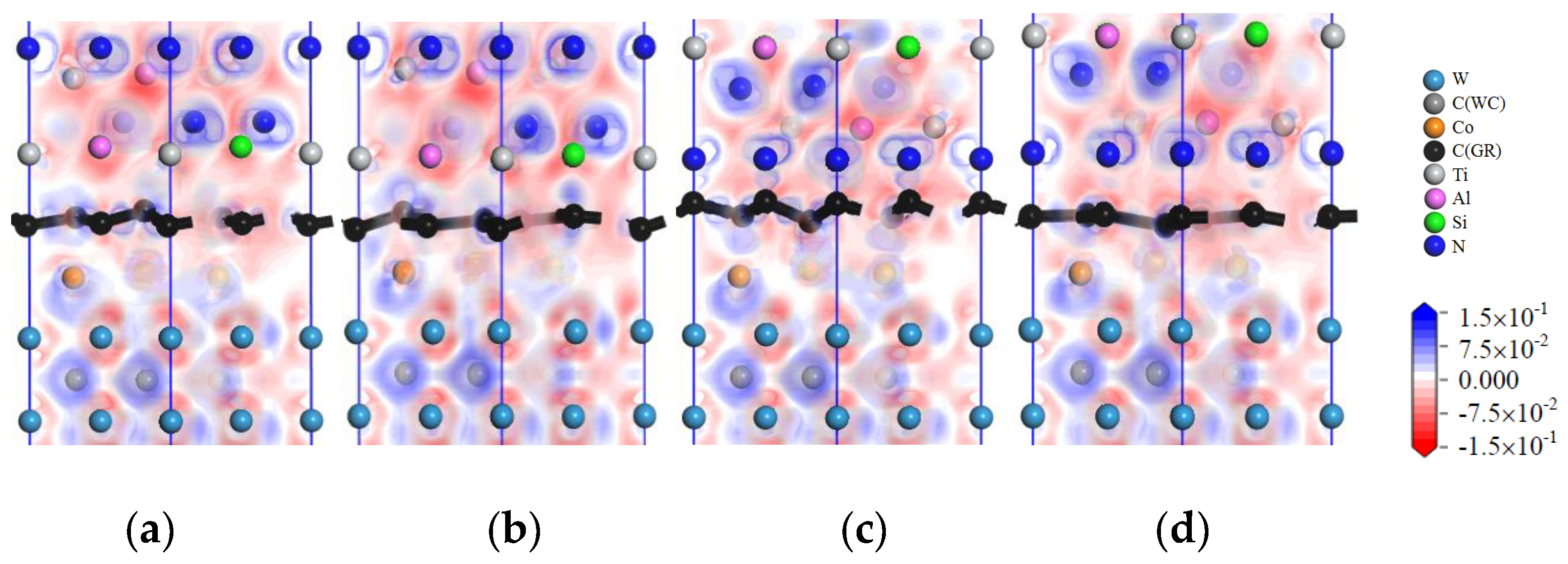
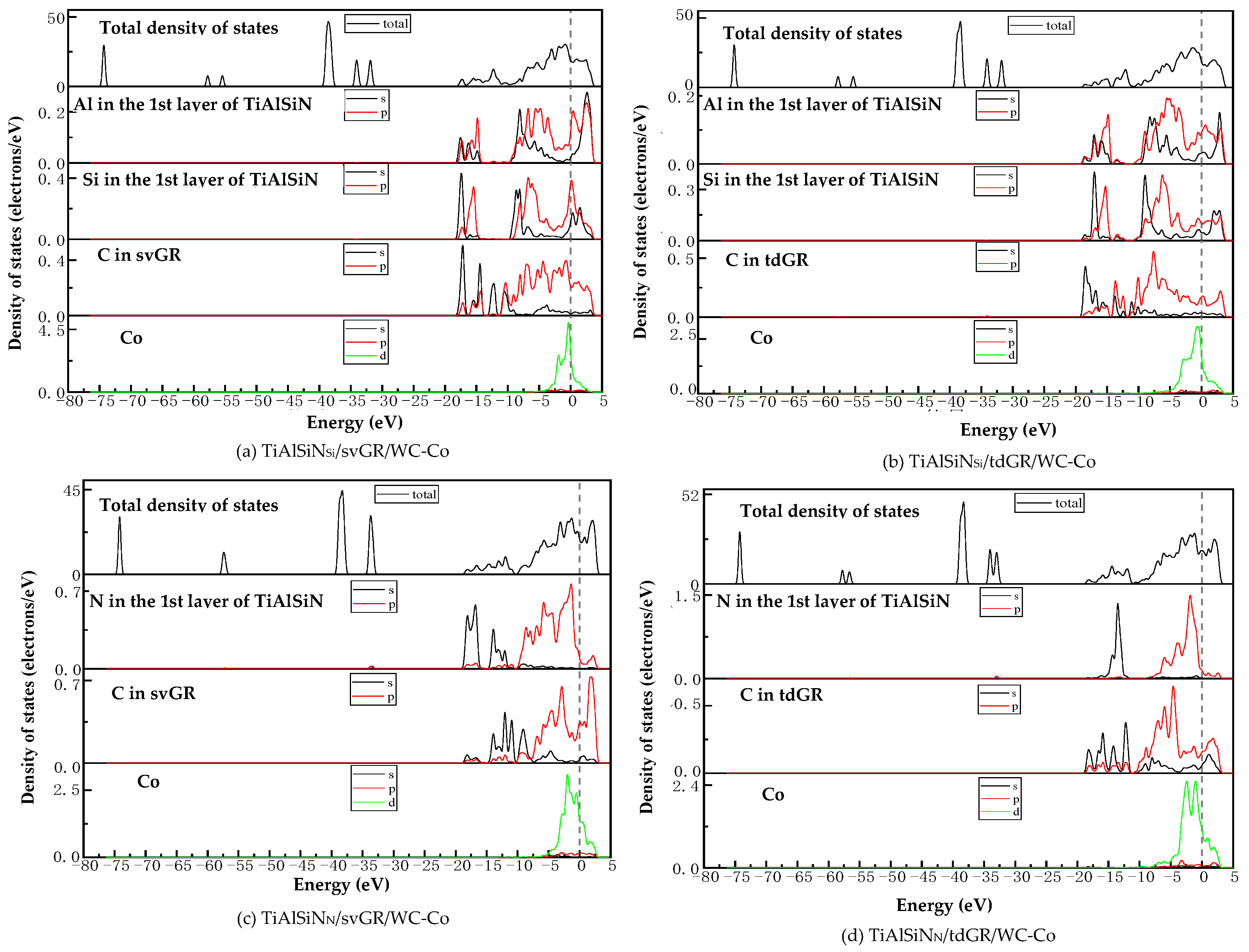
Figure 10 shows images of the calculated charge-density difference of four interface models in which the matrix is doped with defective graphene. It is found that when the matrix is doped with defective graphene, the combination of matrix and defective graphene changes the charge distribution at the interface. There exists electron accumulation between W and C atoms of defective graphene, that is, a covalent bond exists. There are blank areas in the electron clouds between TiAlSiN and Co atoms; the charge density between atoms cannot overlap well, and the bonding between Co and Al and Si and N atoms is weak. There are also blank areas in the charge density between Co and defective graphene, and the bonding between Co and C atoms is weak, which reduces the interface bonding properties of TiAlSiN
Si/WC/svGR/Co, TiAlSiN
Si/WC/tdGR/Co, TiAlSiN
N/WC/svGR/Co, and TiAlSiN
N/WC/tdGR/Co.
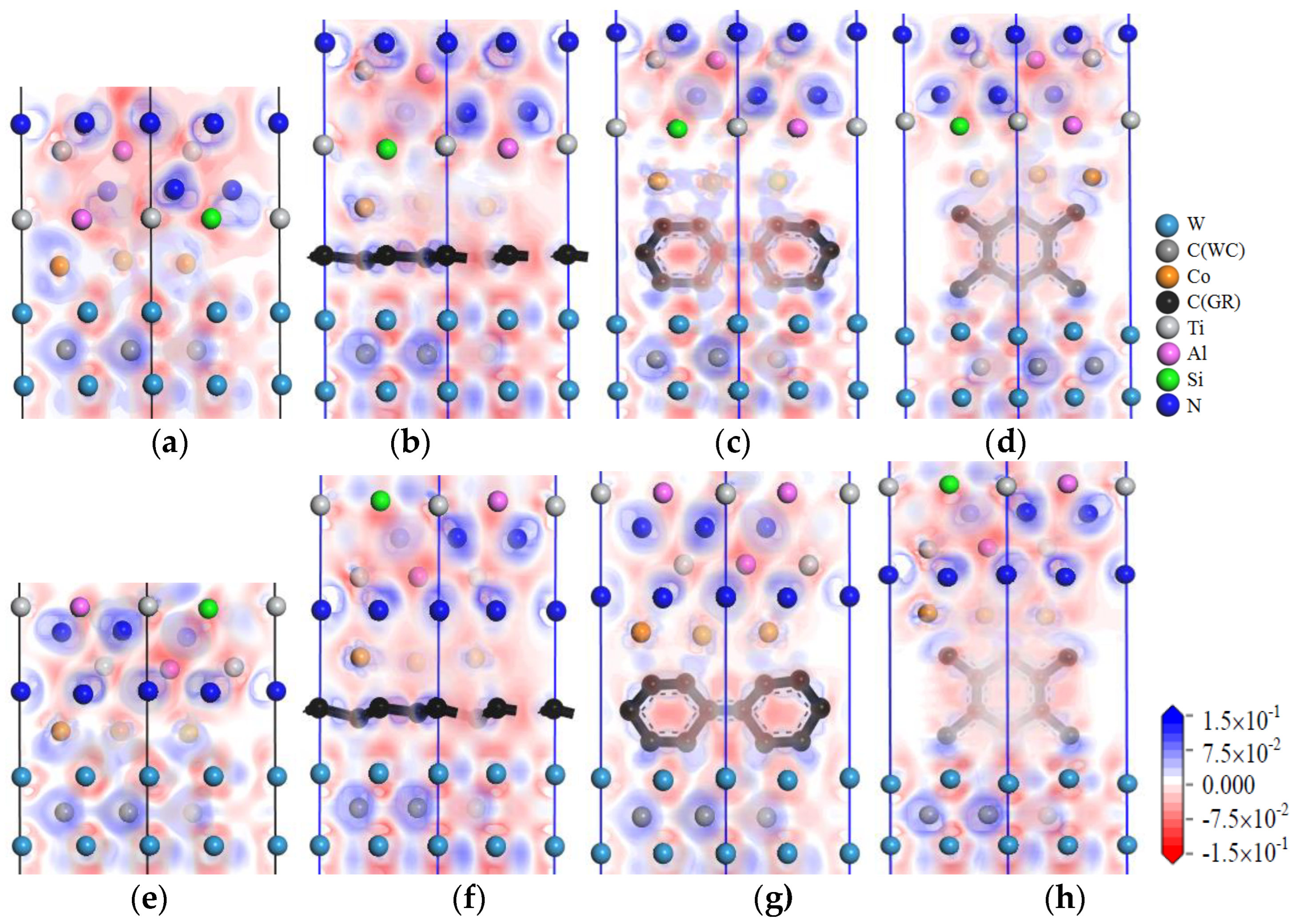
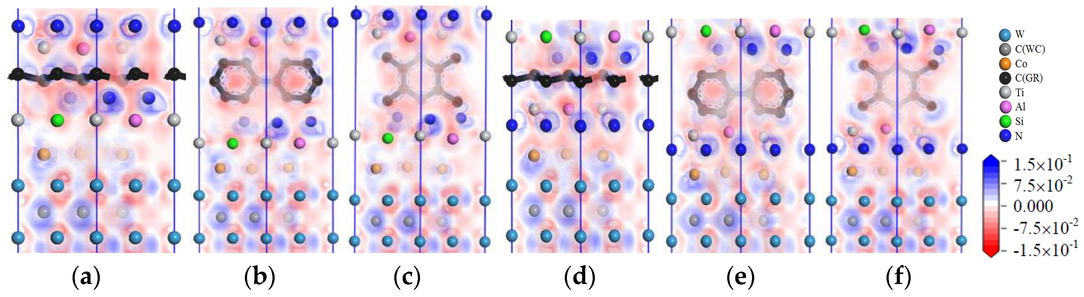
Figure 11 shows images of the charge-density difference of the interface models with intrinsic graphene doping in the coating. When the coating is doped with msGR, in the model of TiAlSiN/msGR/TiAlSiN
Si/WC-Co, shown in
Figure 11a, there are electronic blank areas between Al, Si, and Co atoms, and the force between the atoms is relatively small. In the model of TiAlSiN/msGR/TiAlSiN
N/WC-Co, shown in
Figure 11d, there is electronic overlap between N and Co, and the bonding force between atoms is relatively large. There are many electrons overlapping between atoms in the other interfaces, and the interface bonding property is strengthened. When the coating is doped with an intrinsic graphene boundary, the charge between atoms at the interface between TiAlSiN and Co is thin, and the interatomic force is weakened, resulting in the decrease in the bonding property of the TiAlSiN/WC-Co interface. Compared with the coating without graphene doping, when the coating is doped with graphene, there are more electron blank areas between atoms at the interface of the Si terminal model, and the interatomic force is small. It can be seen that the interface bonding property decreases most obviously when the Si terminal model is doped with graphene, which is consistent with the results shown in
Table 4 and
Table 5, which indicate that the adhesion work of the Si terminal model is less than that of the N terminal model when the coating is doped with msGR and zzGR.
Figure 12 shows the image of the charge-density difference of interface models in which the coating is doped with defective graphene. In
Figure 12a, there are charge blank areas between Al, Si, and Co in TiAlSiN/svGR/TiAlSiN
Si/WC-Co, and the interatomic force is weak. As shown in
Figure 12b, there are charge blank areas between Al, Si, and Co in TiAlSiN/tdGR/TiAlSiN
Si/WC-Co. In
Figure 12c, there are many electrons overlapping between C and N, Al atoms, and between Co and N atoms in TiAlSiN/svGR/TiAlSiN
N/WC-Co, and the interatomic force is strong. In
Figure 12d, the charge density between C and Al atoms and between Co and N atoms is thin, and the force between atoms is weak. Therefore, only the atomic charges overlap more at the interface of TiAlSiN/svGR/TiAlSiN
N/WC-Co, and the interatomic force is strong. In other cases, the doping of defective graphene weakens the bonding force between atoms at the interface.
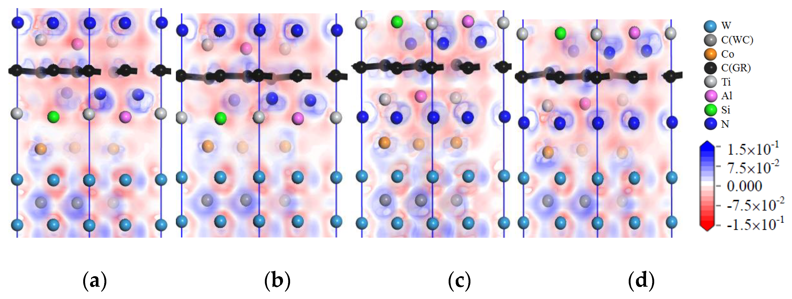
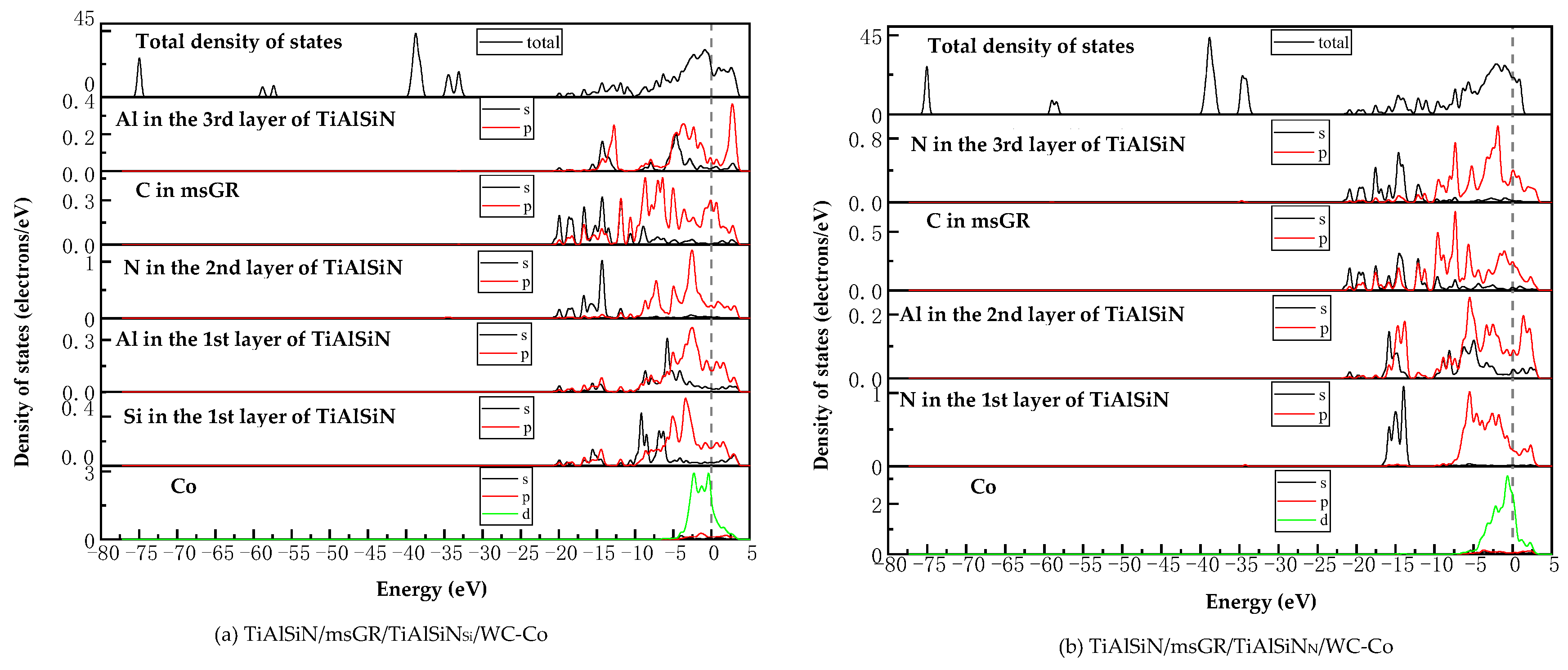
Figure 13 shows images of the charge-density difference of the interface models with intrinsic graphene doping in the coating/matrix interface. When the coating/matrix interface is doped with msGR, at the TiAlSiN
Si/msGR/WC-Co interface, there are charges transferred between C atoms of msGR and Al atom, and there are shared charges between C and Si atoms. The charge density between Co and C atoms is thin, and the interatomic force is small. At the interface of TiAlSiN
N/msGR/WC-Co, there are obvious shared charges between C atoms of msGR and N, Co atoms, and the interatomic force is strong. When the coating/matrix interface is doped with the graphene boundary, the combination of coating/matrix interface and graphene boundary makes the charge between atoms thin. The interatomic force decreases, and the interface bonding property decreases. Compared with the N terminal model, when the coating/matrix interface is doped with msGR and zzGR, there are more electronic blank areas at the interface of the Si terminal model, and the interatomic force is small, and the interface bonding property decreases. It can be seen that the interface bonding property decreases most obviously when the Si terminal model is doped with graphene, and the results are consistent with those given in
Table 6 and
Table 7.
Figure 14 shows images of the charge-density difference of interface models with defective graphene doping in the coating/matrix interface. As shown in
Figure 14a, in the model of TiAlSiN
Si/svGR/WC-Co, the charge density between Al, Si, and Co atoms is thin, there are charge blank areas between C and Co atoms, and the interatomic force is weak. In
Figure 14b, in the model of TiAlSiN
Si/tdGR/WC-Co, the charge density between Al, Si, and C atoms is thin. The charge density between Co and C atoms is thin and there are blank areas. In
Figure 14c, in the model of TiAlSiN
N/svGR/WC-Co, the electrons between C and N atoms and between C and Co atoms all overlap more, and the bonding force is strong. In
Figure 14d, in the model of TiAlSiN
N/tdGR/WC-Co, the charge density between C and Co atoms is thin, and the interatomic force is weak. Summarizing, only the atomic charges at the interface of TiAlSiN
N/svGR/WC-Co overlap more, and the bonding force between atoms is strong. In other cases, the defective graphene doping weakens the bonding force between atoms at the interface, and the interface bonding property decreases.
(2) Density of states (DOS)
Analyzing the density of states can explore the bonding situation from the perspective of electron orbital hybridization.
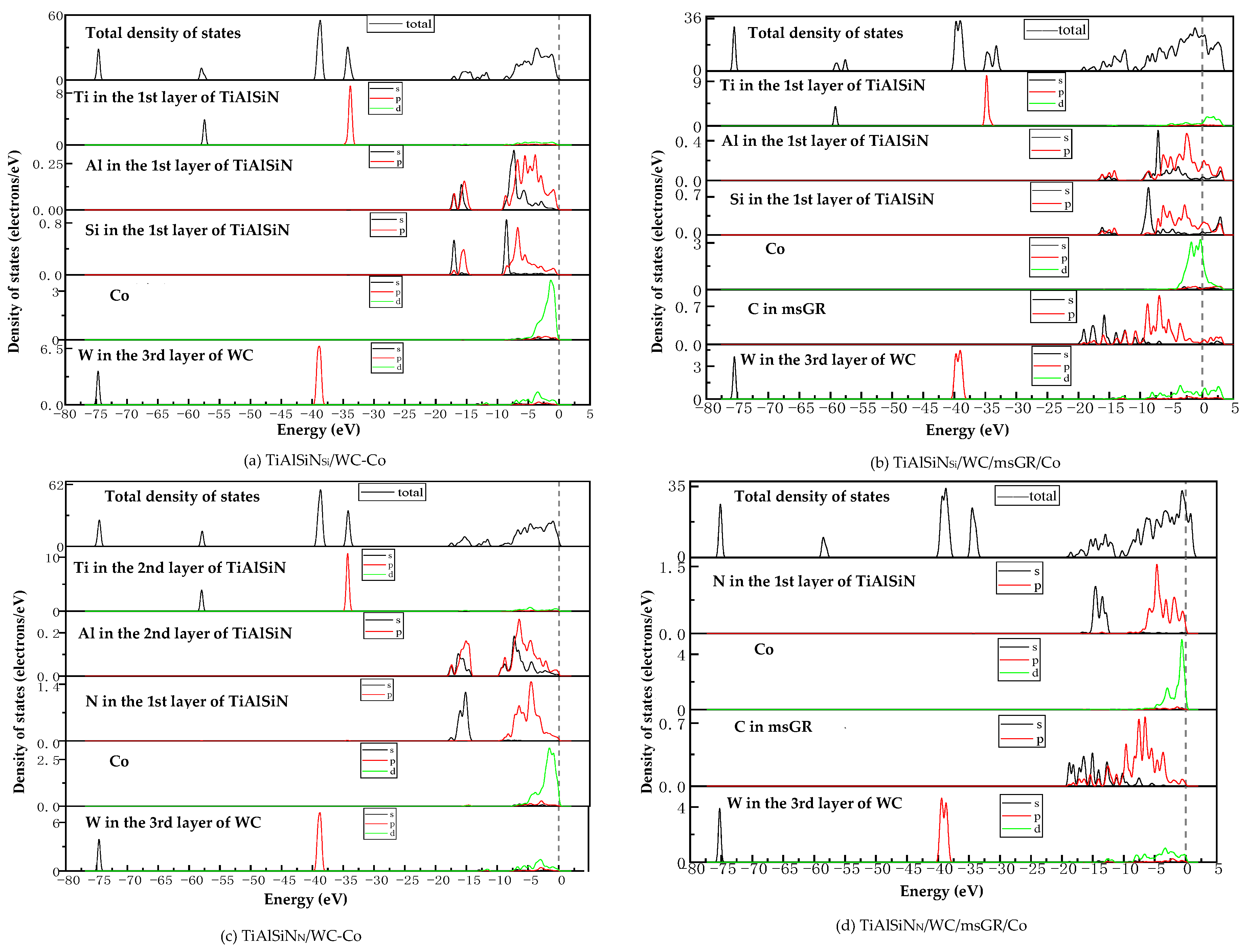
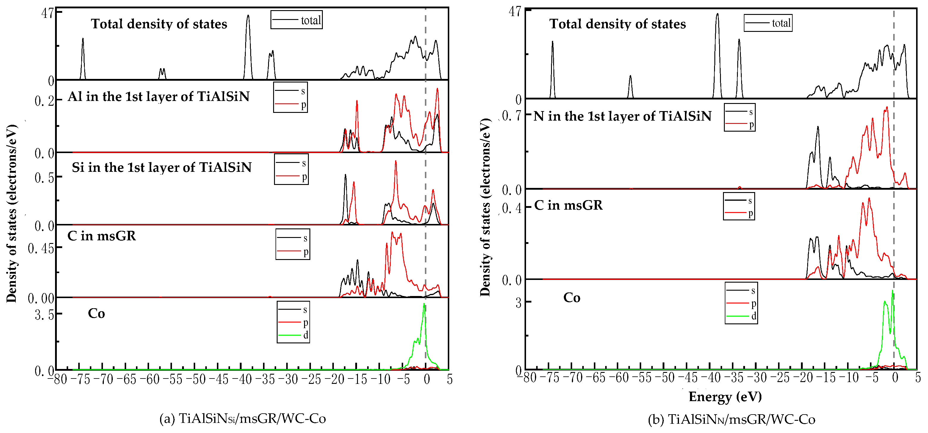
Figure 15a,c are the images of the total density of states (TDOS) and the partial density of states (PDOS) of the interface models without doping graphene. At the Fermi level, the TDOS of the interface models is not zero, indicating a metallic character for the interface. As shown in
Figure 15a, the remarkable DOS feature of TiAlSiN
Si/WC-Co is that its peak is mainly contributed by p orbital electrons of Ti atoms and W atoms, and the interaction between Si and Co at the interface is mainly the hybridization of p electrons of Si and d electrons of Co, forming Si/Co covalent bonds.
Figure 15b,d are the images of TDOS and PDOS of the interface models with the matrix doped with msGR. In
Figure 15b, the density of states of Al, Si, and Co atoms of TiAlSiN
Si/WC/msGR/Co overlaps in the range −5~5 eV, and the orbital hybridization is generated by Al-s, Si-s, and Co-d, forming Al/Co bonds and Si/Co bonds. Compared with
Figure 15a without graphene doping, the covalent effect of the Si/Co bond is stronger, which explains the essential mechanism that the adhesion work value of TiAlSiN
Si/WC/msGR/Co is higher than that of TiAlSiN
Si/WC-Co.
A shown in
Figure 15c, the remarkable feature of the density of states of TiAlSiN
N/WC-Co is that its peak is mainly contributed by p orbital electrons of Ti and W atoms, and the interaction between N and Co at the interface is mainly the hybridization of p electrons of N and d electrons of Co, forming N/Co covalent bonds. In
Figure 15d, at the TiAlSiN
N/WC/msGR/Co interface, the density of states of N and Co atoms overlaps on the left side of Fermi level, and N-s and Co-d produce orbital hybridization, forming N/Co bonds. On the left side of Fermi level, the density of states of the C atom, Co atom, and W atom is orbitally hybridized by C-p with Co-d and W-d, forming C/Co and C/W bonds. Compared with
Figure 15c, the electronic orbital hybrid region of N/Co, C/Co, and C/W bonds changes little, and the peak change in density of states of interface atomic interaction is small, and the bonding strength is stable. Therefore, the adhesion work of TiAlSiN
N/WC/msGR/Co is greater than that of TiAlSiN
N/WC-Co.
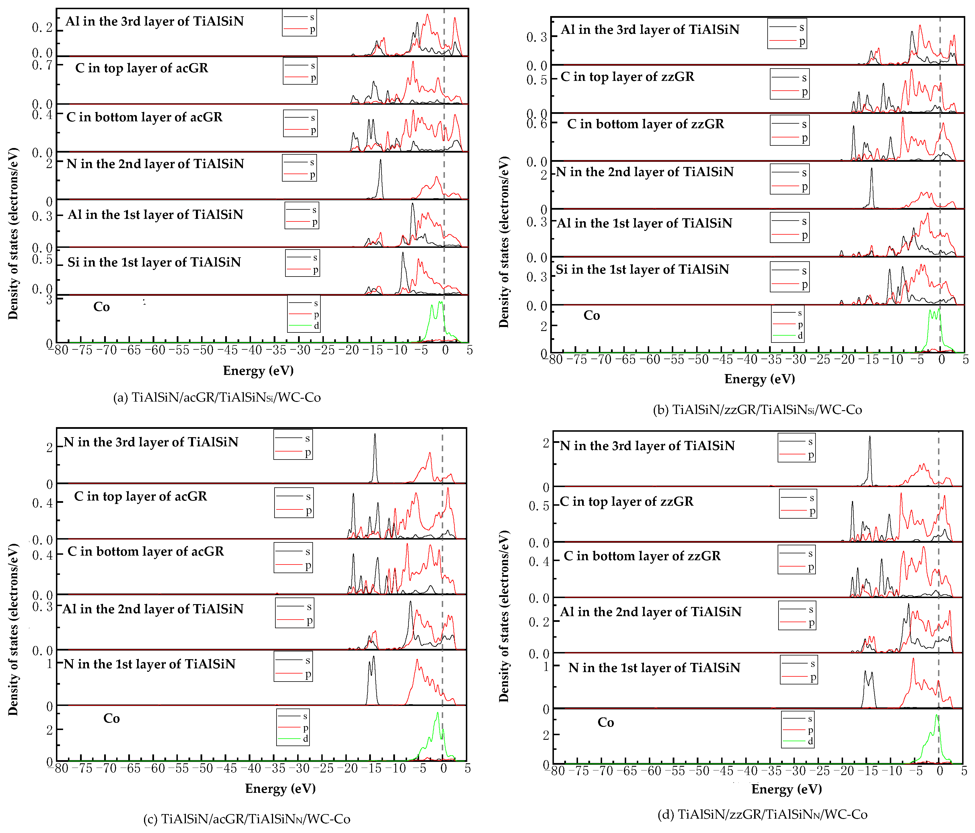
Figure 16 shows the images of TDOS and PDOS of the interface models with the matrix doped with an intrinsic graphene boundary. Compared with undoped graphene, when the matrix is doped with an intrinsic graphene boundary, C-p of C atoms at the graphene boundary, Co-d and W-d produce orbital hybridization, forming C/Co and C/W bonds. The degree of electronic orbital hybridization of Al, Si, N, and Co atoms at the TiAlSiN interface is weak, and the bonding effect is weak, which leads to the decrease in the bonding property of the TiAlSiN/WC-Co interface. Therefore, the adhesion work of the TiAlSiN/Co interface of different terminal models with matrix doped with an intrinsic graphene boundary is less than that of TiAlSiN/Co interface without graphene doping.
Figure 17 shows the images of TDOS and PDOS of the interface models with the matrix doped with defective graphene. As shown in
Figure 17a, C-p of C atom of svGR, Co-d, and W-d produce orbital hybridization, forming C/Co and C/W bonds. The density of states of Al, Si, and Co atoms overlaps in the range −5~0 eV. The density of states of the Si atom is low, and the degree of hybridization with Co-d orbitals is weak. In
Figure 17b, the density of states of Al, Si, and Co atoms in the overlapping range in TiAlSiN
Si/WC/tdGR/Co is low, below 0.2 eV, and the degree of orbital hybridization of Al-p, Si-p, and Co-d is weak. In
Figure 17c, the density of states region of Co atoms in TiAlSiN
N/WC/svGR/Co is narrow, resulting in low orbital hybridization of Co-d with C-p and N-p, and weak interatomic bonding force. In
Figure 17d, the orbital hybridization degree of N-p and Co-d in TiAlSiN
N/WC/tdGR/Co is low, and the interatomic bonding force is weak. This explains the essential mechanism that the interface adhesion work of TiAlSiN/WC-Co decreases when its matrix is doped with defective graphene.
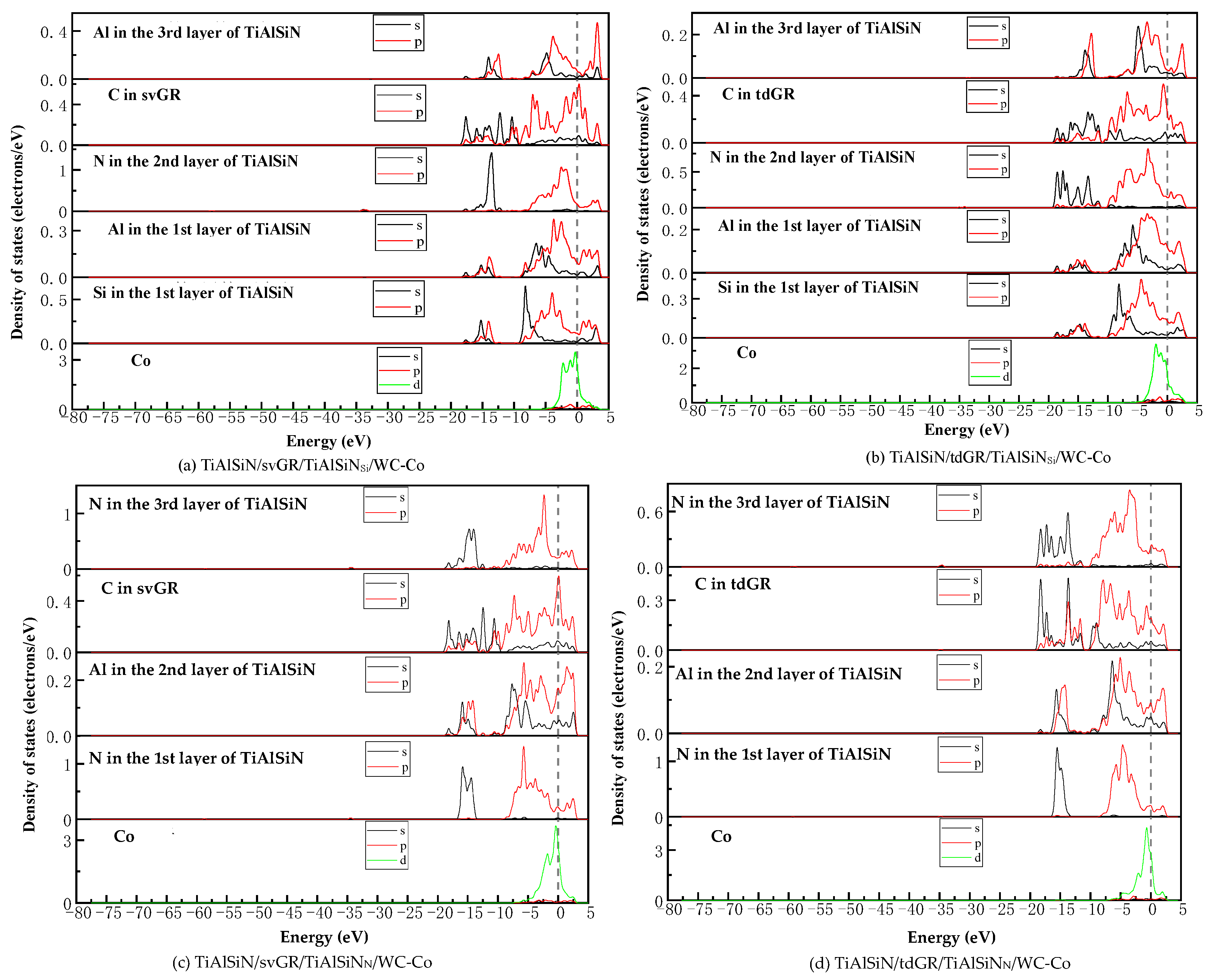
Figure 18 shows the images of TDOS and PDOS of the interface models with the coating doped with msGR. As shown in
Figure 18a, at the interface of TiAlSiN/msGR/TiAlSiN
Si/WC-Co, the charges between Al, Si, and Co atoms are rearranged, and at Fermi level, Al, Si, and Co atoms at the interface produce orbital hybridization, forming covalent bonds. Compared with
Figure 15a without graphene doping, the covalent effect is weak, which explains the essential mechanism that the adhesion work value of TiAlSiN/msGR/TiAlSiN
Si/WC-Co is higher than that of TiAlSiN
Si/WC-Co. In
Figure 18b, in the model of TiAlSiN/msGR/TiAlSiN
N/WC-Co, N-s and C-s produce orbital hybridization in the range −22~15 eV, and N-p and C-p produce orbital hybridization in the range −10~3 eV, forming N/C bonds. Al-s, Al-p and C-s, and C-p produce orbital hybridization in the range −17~3 eV, forming Al/C bonds. N-p and Co-d produce orbital hybridization in the range −5~3 eV, forming N/Co bonds. The density of atomic states of forming chemical bonds and orbital hybridization degree is high, which explains the essential mechanism that the adhesion work of TiAlSiN/msGR/TiAlSiN
N/WC-Co is greater than that of TiAlSiN
N/WC-Co.
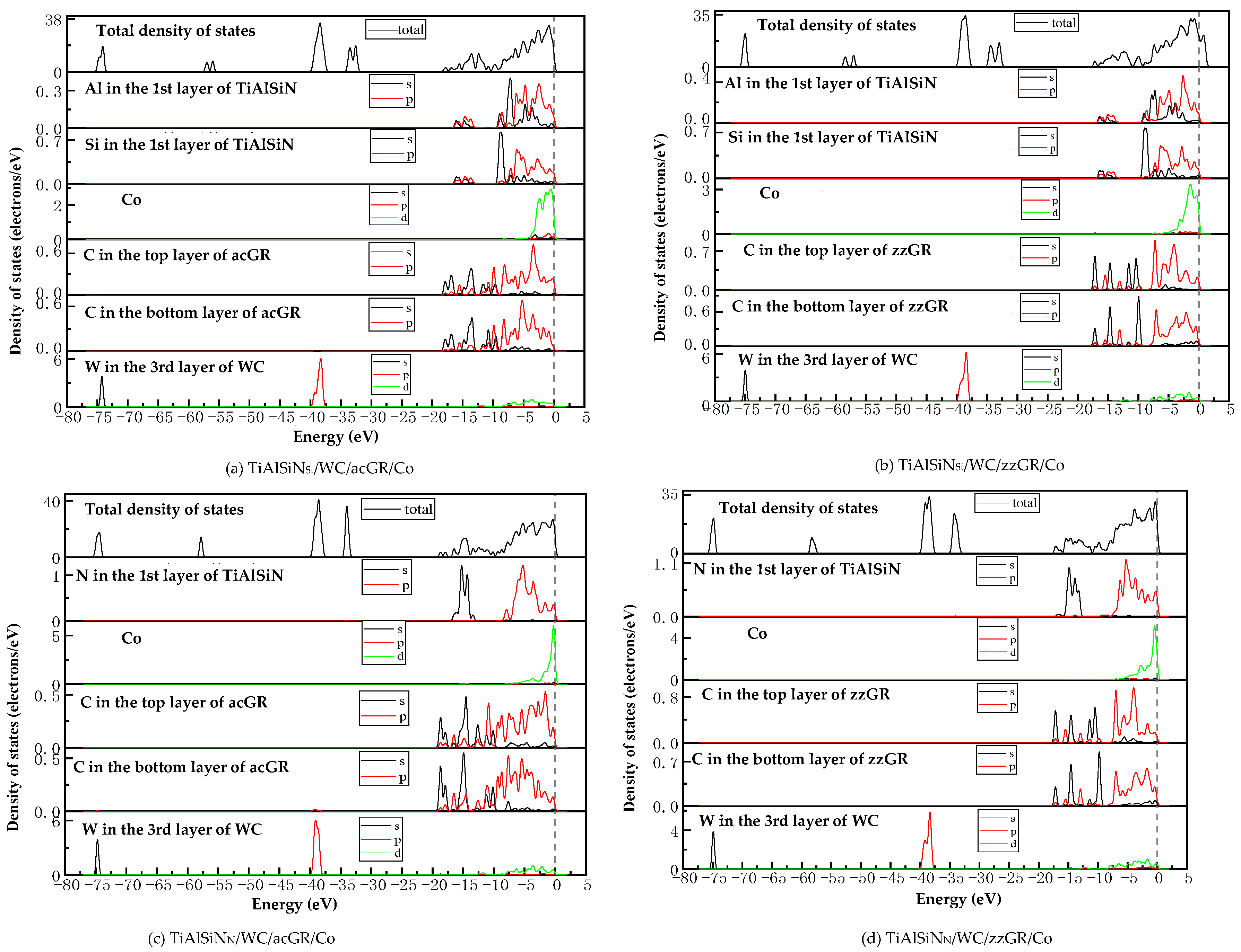
Figure 19 shows the images of PDOS of the interface models with the coating doped with an intrinsic graphene boundary. As shown in
Figure 19a, the density of states of N-p and C-p in the model of TiAlSiN/acGR/TiAlSiN
Si/WC-Co overlaps in the range −6~3 eV, the N-p density of states is below 0.1 eV, and the energy is low, and the N/Co bond is weak. The density of states of Al and Si atoms is low, below 0.3 eV, and the degree of hybridization with Co-d orbitals is weak. In
Figure 19b, the density of states of Al-p and Si-p is low, less than 0.3 eV, and the degree of hybridization with Co-d orbitals is weak. In
Figure 19c, at the TiAlSiN/acGR/TiAlSiN
N/WC-Co interface, the charges between N and Co atoms are rearranged, and at the Fermi level, N and Co atoms at the interface produce orbital hybridization, and the degree of orbital hybridization is low, forming weak covalent bonds. In
Figure 19d, at the interface of TiAlSiN/zzGR/TiAlSiN
N/WC-Co, Co and N atoms produce orbital hybridization, the hybridization area is small, and the energy is low, and the Co/N bond is weak. This explains the essential mechanism for the decrease in adhesion work at the TiAlSiN/WC-Co interface when the coating is doped with an intrinsic graphene boundary.
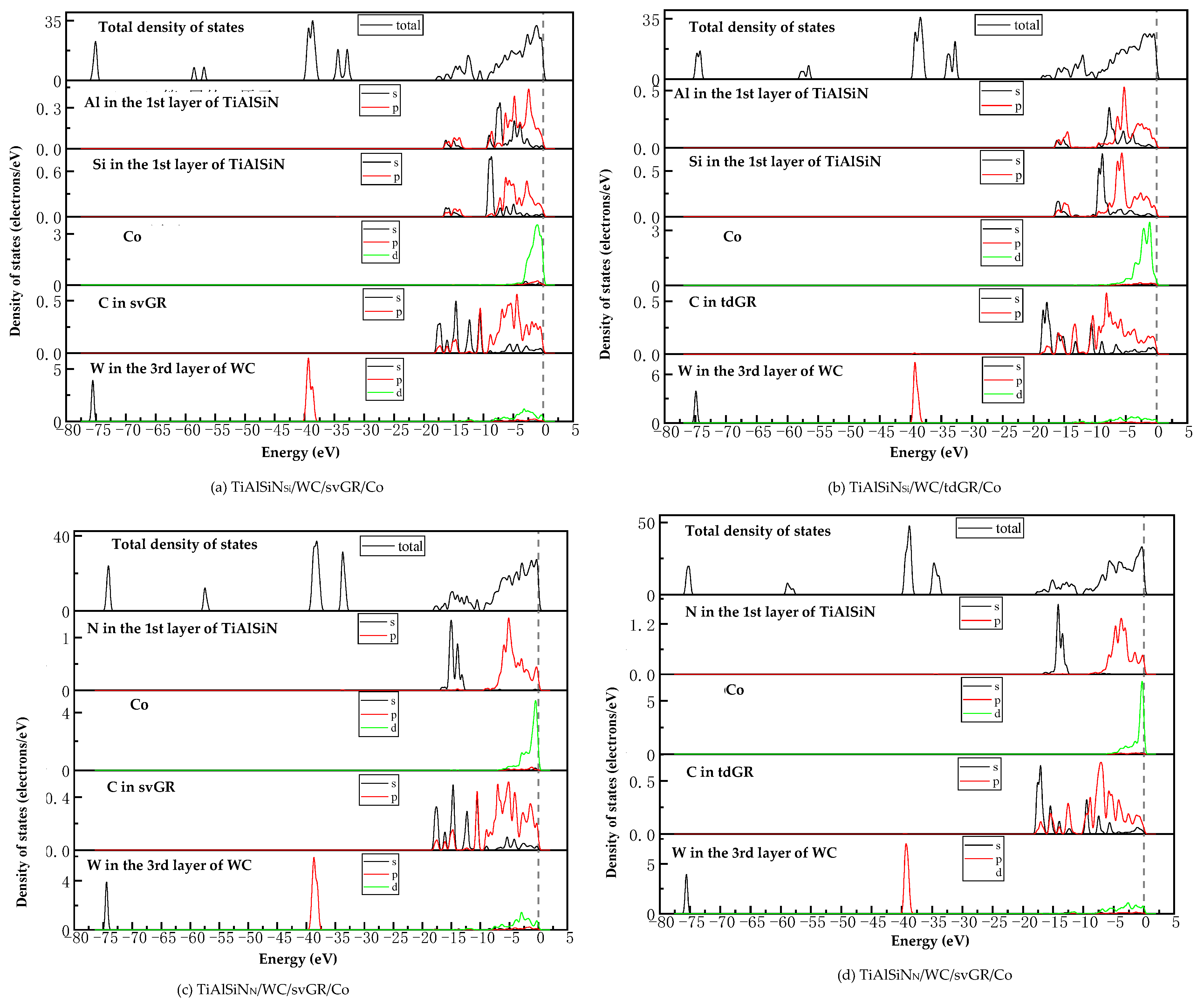
Figure 20 shows the images PDOS of the interface models with the coating doped with defective graphene. As shown in
Figure 20a, the Co-d, Al-p, and Si-p in the model of TiAlSiN/svGR/TiAlSiN
Si/WC-Co produce orbital hybridization in the range −4~3 eV, and the degree of hybridization is low, forming weak Co/Si bonds. In
Figure 20b, the density of states of Al, Si, and Co atoms in TiAlSiN/tdGR/TiAlSiN
Si/WC-Co overlaps in the range −4~3 eV, where the density of states of Co is low, and the degree of orbital hybridization of Al-p, Si-p, and Co-d is weak. In
Figure 20c, C-p and N-p, Al-p, Co-d, and N-p orbital hybridization regions in TiAlSiN/svGR/TiAlSiN
N/WC-Co are wide, and the C/N, C/Al, and Co/N bonds are strong. In
Figure 20d, the degree of orbital hybridization of C-p and N-p, and Al-p in TiAlSiN/tdGR/TiAlSiN
N/WC-Co is high, while the N-p density of states is low, and the degree of orbital hybridization of Co-d and N-p is weak, and bonding force is weak. Therefore, the interface adhesion work of TiAlSiN/svGR/TiAlSiN
N/WC-Co is greater than that of TiAlSiN
N/WC-Co without graphene doping; in other cases, doping defective graphene in the coating reduces the interface adhesion work of the model.
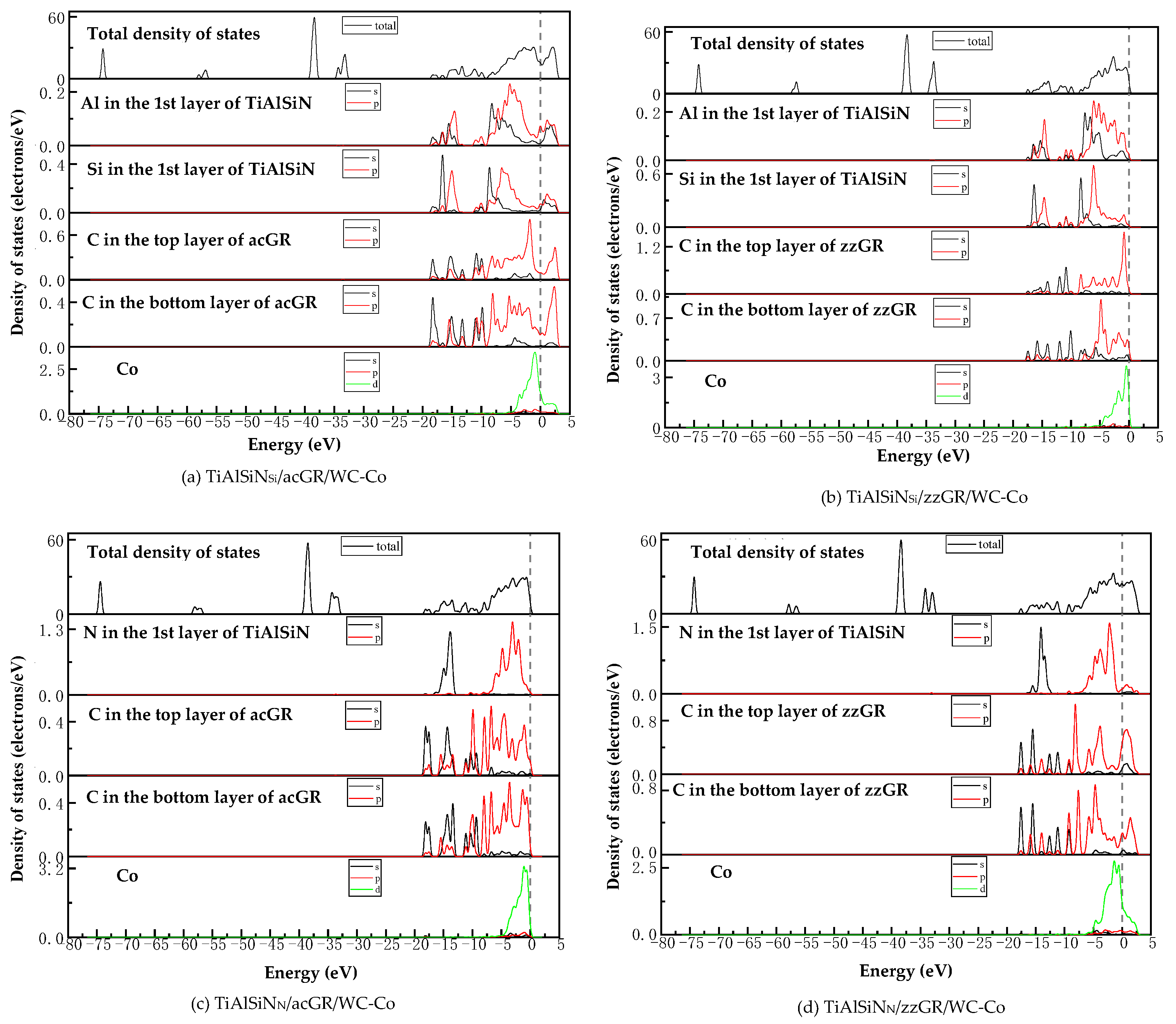
Figure 21 shows the images of TDOS and PDOS of the interface models with the coating/matrix interface doped with msGR. As shown in
Figure 21a, at the interface of TiAlSiN
Si/msGR/WC-Co, the density of states of Al and Si atoms overlaps with C atoms of msGR in the range −10~3 eV, and Al-s, Al-p, Si-p, and C-p produce orbital hybridization, forming Al/C and Si/C bonds. The density of states of Co and C atoms overlaps in the range −5~3 eV, and the density of states of C atoms in the overlapping region is very low, the region of density of states of Co is narrow, and the Co/C bond formed by the orbital hybridization of Co-d and C-p is weak, which explains the essential mechanism that the adhesion work of TiAlSiN
Si/msGR/WC-Co is less than that of TiAlSiN
Si/WC-Co. In
Figure 21b, at the interface of TiAlSiN
N/msGR/WC-Co, the density of states of N and C atoms of msGR overlaps in the range −20~10 eV, and the N-s and C-s produce orbital hybridization. In the range −10~3 eV, N-p and C-p produce orbital hybridization, which forms strong N/C bonds. The density of states of Co and C atoms overlaps in the range −5~3 eV, and Co-d and C-p produce orbital hybridization, forming strong Co/C bonds, which explains the essential mechanism that the adhesion work of TiAlSiN
N/msGR/WC-Co is greater than that of TiAlSiN
N/WC-Co.
Figure 22 shows the images of TDOS and PDOS of the interface models with the coating/matrix interface doped with an intrinsic graphene boundary. As shown in
Figure 22a, for the model of TiAlSiN
Si/acGR/WC-Co, the Al-s, Al-p, Si-s, and C-p produce orbital hybridization in the range −10~3 eV, forming Al/C and Si/C bonds. The Co-d and C-p produce orbital hybridization, and the degree of hybridization is low, forming weak Co/C bonds. In
Figure 22b, the density of states of C-p and Co-d in TiAlSiN
Si/zzGR/WC-Co overlaps in the range −5~0 eV, the C-p density of states is low, and the C/Co bond is weak. In
Figure 22c, in the model of TiAlSiN
N/acGR/WC-Co, the density of states of C-p and N-p overlaps in the range −7~0 eV, the C-p density of states is low, and the N/C bond is weak. In
Figure 22d, the density of states of N-p and C-d overlaps in the range −7~0 eV. The degree of orbital hybridization between N-p and C-p is low, and N/C bond is weak. This explains the essential mechanism of the decrease in adhesion work at the TiAlSiN/WC-Co interface when the coating/matrix interface is doped with an intrinsic graphene boundary.
Figure 23 shows the images of TDOS and PDOS of the interface models with the coating/matrix interface doped with defective graphene. As shown in
Figure 23a, in the model of TiAlSiN
Si/svGR/WC-Co, the density of Al, Si, and C atoms of svGR overlaps in the ranges −17~15 and −10~3 eV. Al-s, Al-p, Si-p, and C-p produce orbital hybridization, forming the Al/C and Si/C bonds. The density of states of Co and C atoms overlaps in the range −4~3 eV. Co-d and C-p produce orbital hybridization, and the degree of hybridization is low, and the Co/C bond is weak. In
Figure 23b, in the model of TiAlSiN
Si/tdGR/WC-Co, the density of Al, Si, and C atoms of svGR overlaps in the ranges −17~15 and −11~3 eV. Al-s, Al-p, Si-s, Si-p, and C-p produce orbital hybridization to form Al/C and Si/C bonds. The density of states of Co and C atoms overlaps in the range −5~4 eV, and Co-d and C-p produce orbital hybridization. The peak value of C-p in the overlapping region is low, and the Co/C bond formed is weak. In
Figure 23c, in the model of TiAlSiN
N/svGR/WC-Co, the density of states of N-s and C-s overlap in the range −15~8 eV. The density of states of N-p and C-p overlap in the range −7~3 eV, and the degree of electron orbital hybridization is high, and the N/C bond is strong. In
Figure 23d, N-p, Co-d, and C-p produce orbital hybridization, the degree of orbital hybridization is low, forming weak N/C and Co/C bonds. Therefore, the interface adhesion work of TiAlSiN
N/svGR/WC-Co is greater than that of TiAlSiN
N/WC-Co without graphene doping. In other cases, doping defective graphene in the coating/matrix interface reduces the interface adhesion work of the model. The analysis results of density of states are consistent with the analysis results of previous adhesion works, which reveals the interface bonding mechanism of graphene-doped TiAlSiN/WC-Co.
The partial research results are consistent with the experimental results in references [
14,
21]. Reference [
14] results showed that WC-Co doped with GR is prone to produce a bending friction layer. The bending and wrapping of the GR surface are the main toughening mechanisms, which increases the interface bonding strength. In the Co/GR and GR/WC interfaces, the C in GR is prone to distribute the electron clouds closer to W and Co; C-W and C-Co form covalent bonds and the interface bonding is strengthened. Li et al. [
21] found that GR could be well attached to WC and around it, thus refining WC grains.


