
Design and Analysis of a PDLC-Based Reconfigurable Hilbert Fractal Antenna for Large and Fine THz Frequency Tuning


Abstract
:1. Introduction
2. Results and Discussion
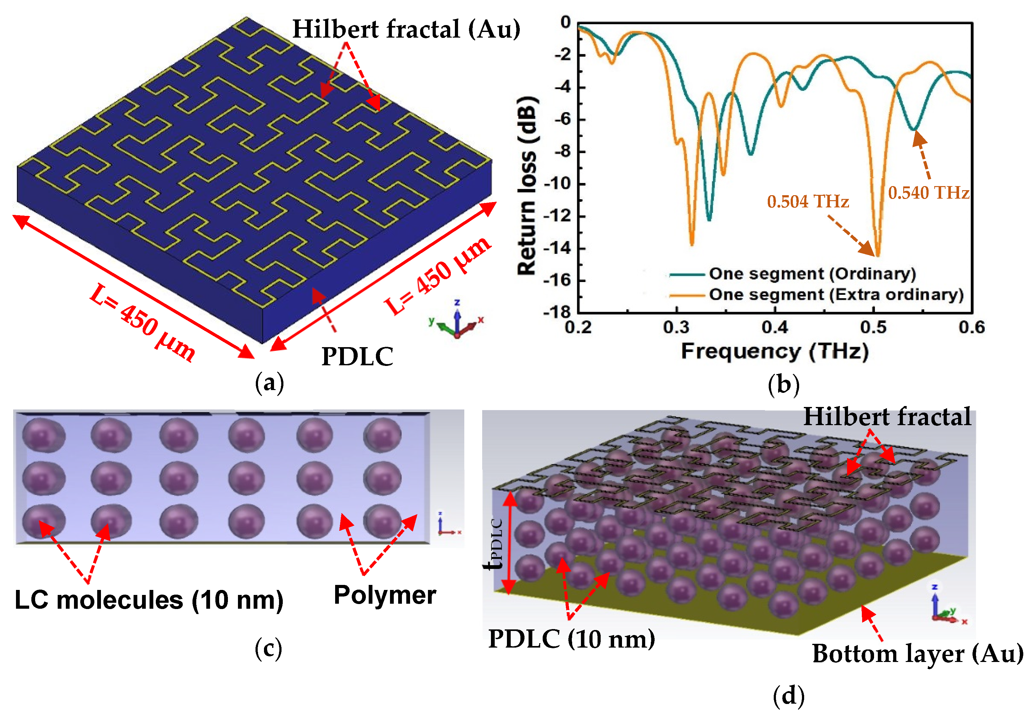
2.1. Large Frequency Shift or Tuning
2.2. Fine Frequency Shift/Continuous Frequency Tuning
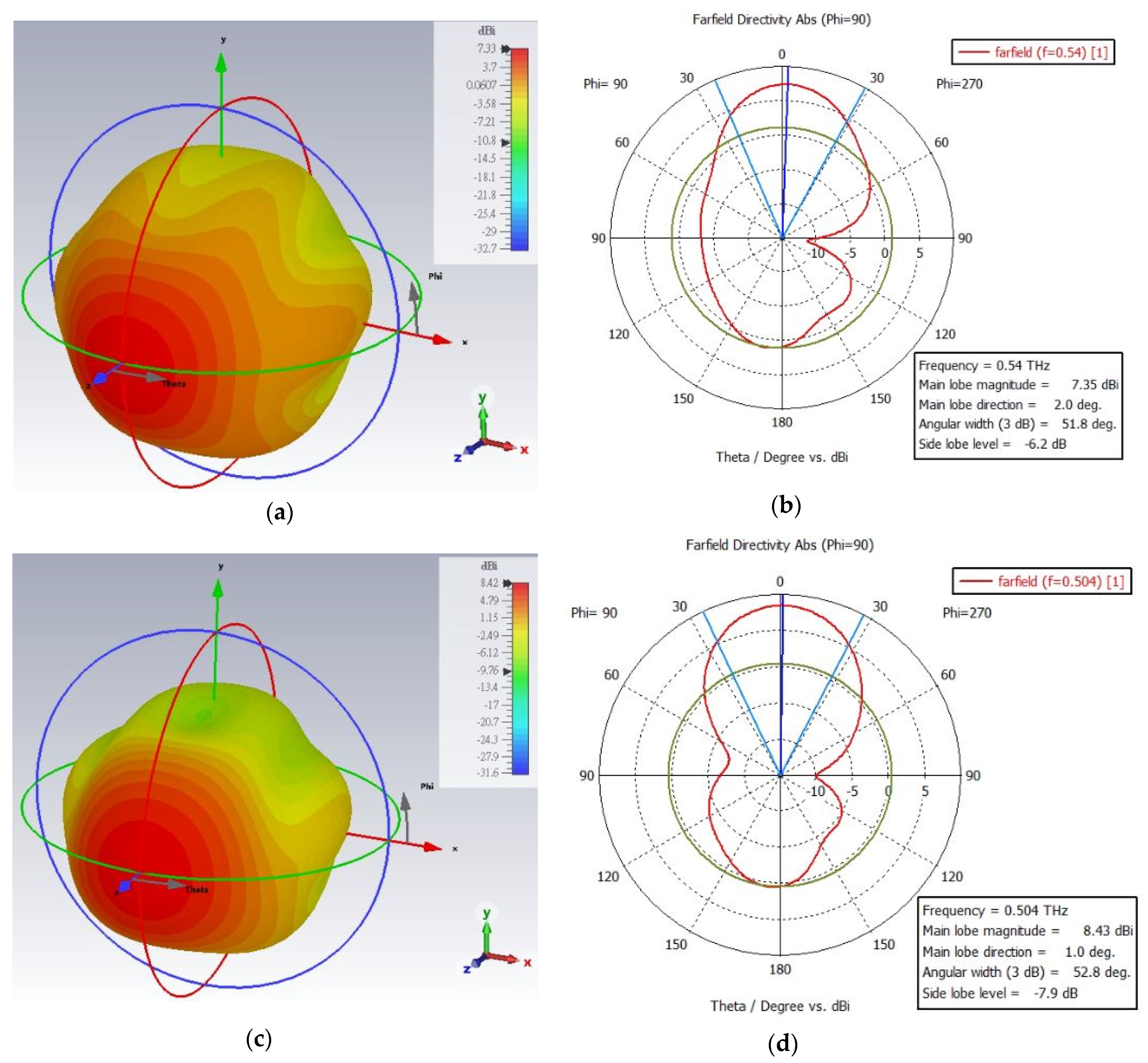
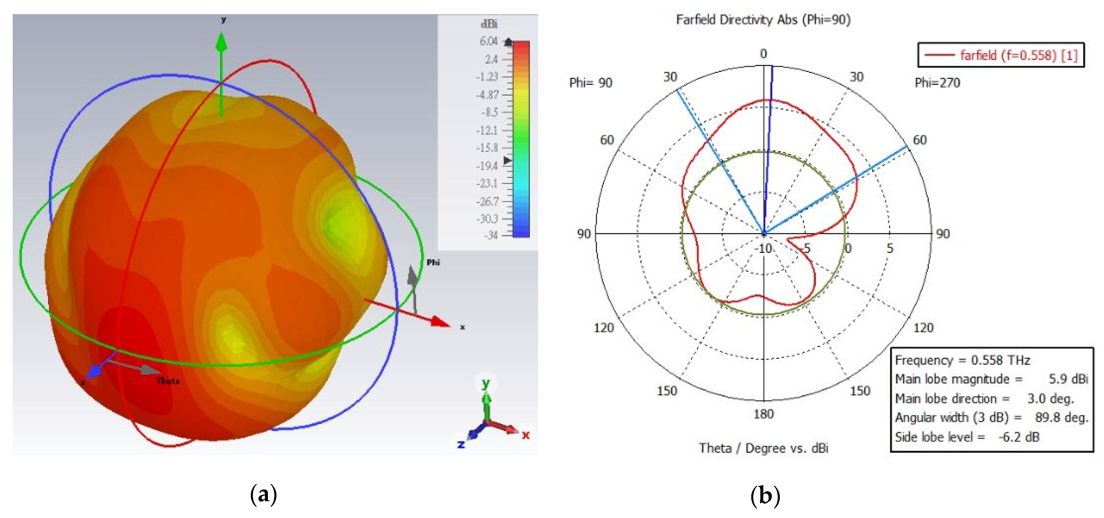
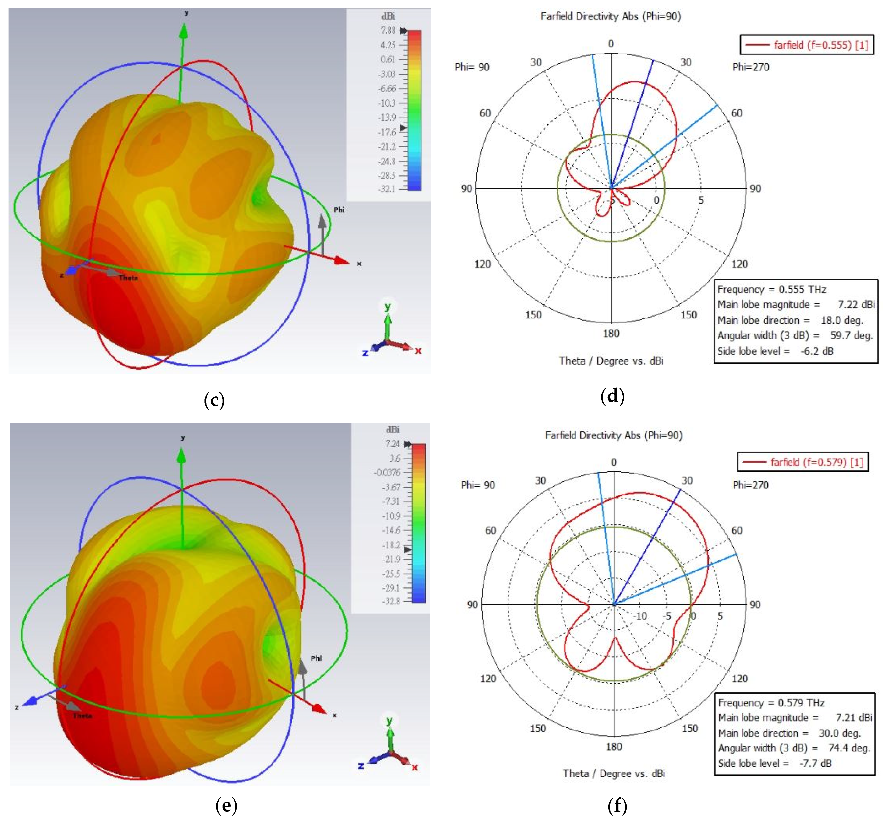
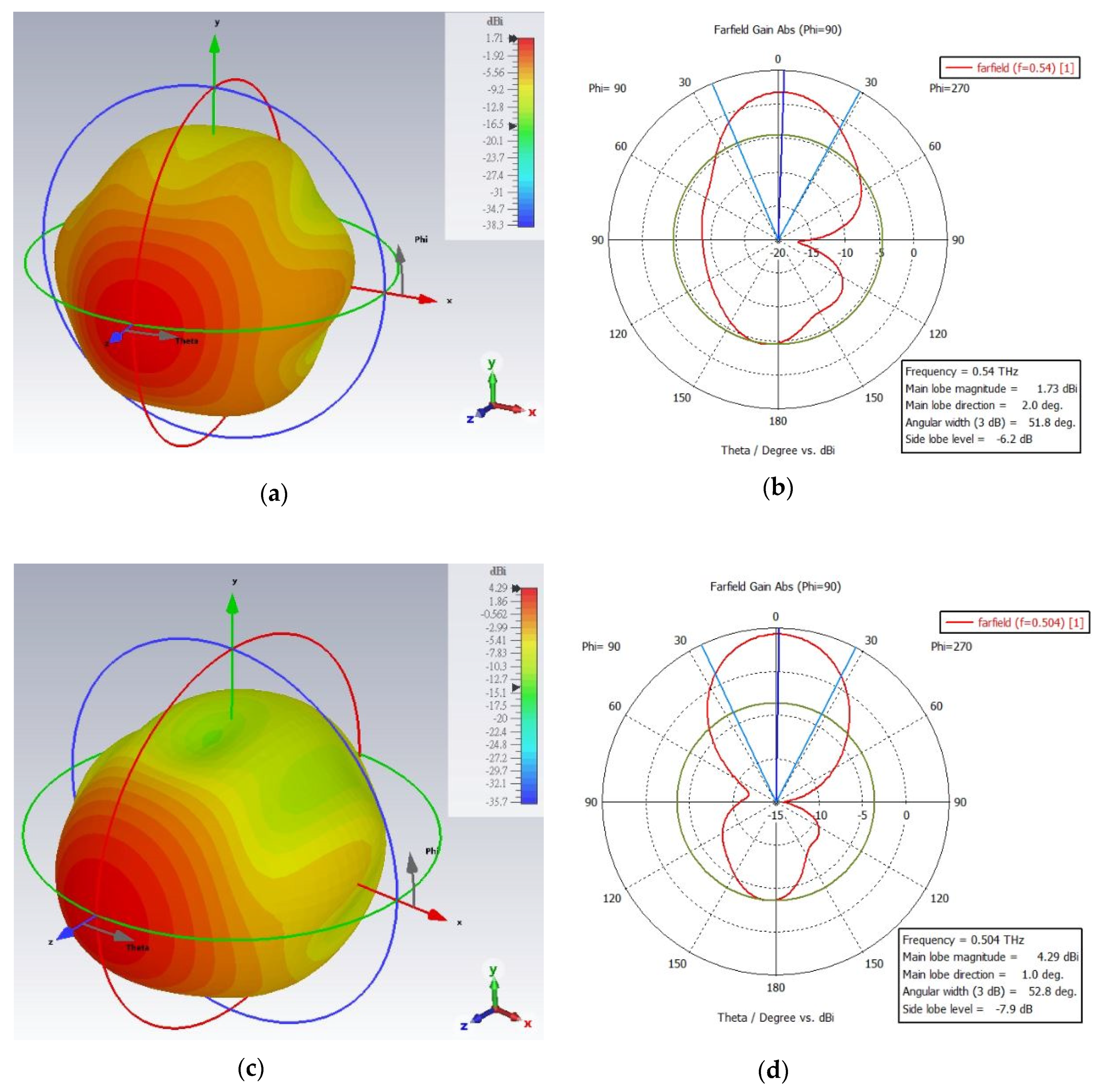
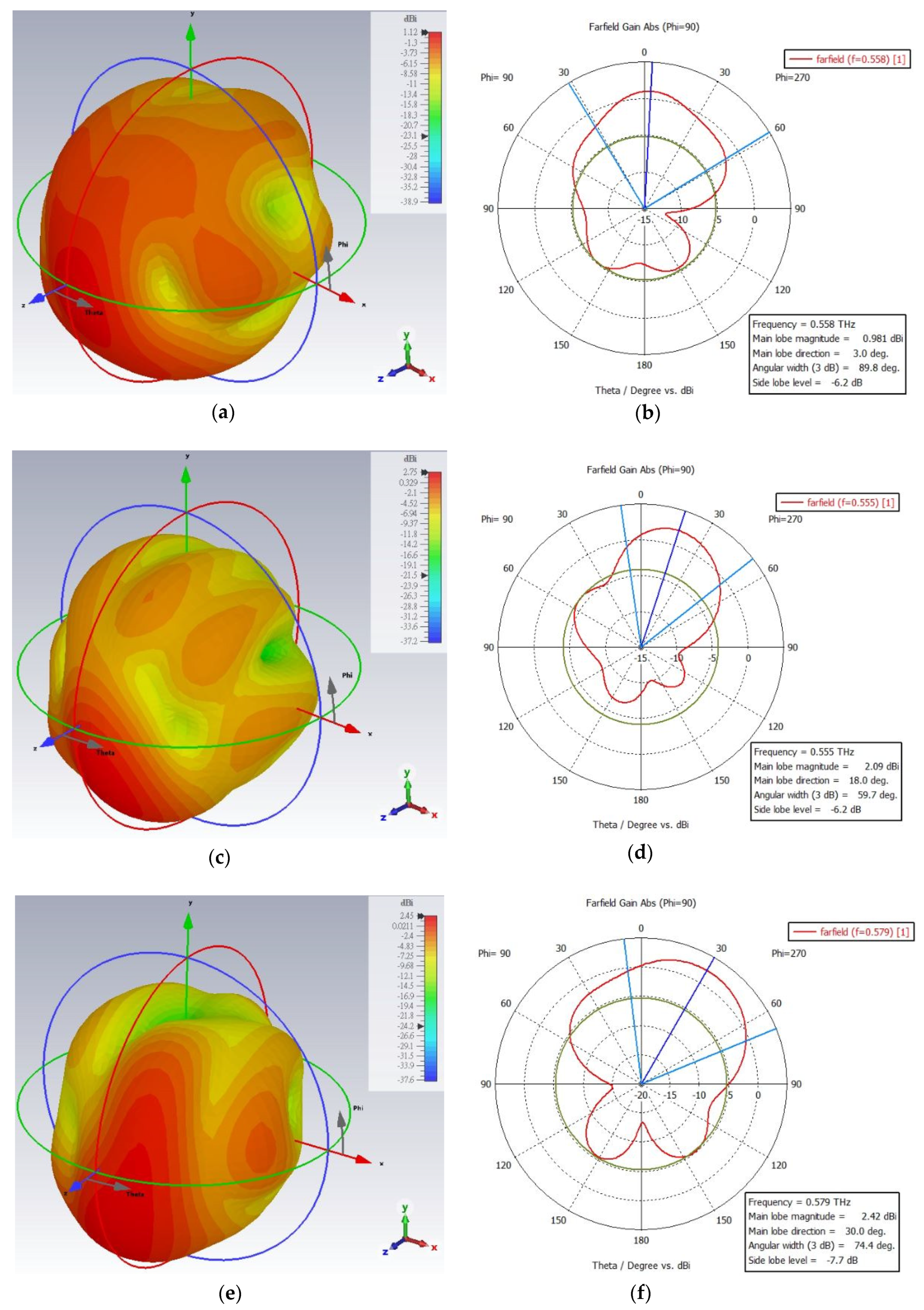
2.3. Farfield Radiation Pattern
3. Conclusions
Author Contributions
Funding
Institutional Review Board Statement
Informed Consent Statement
Data Availability Statement
Conflicts of Interest
References
- Prabhu, P.; Elamaran, E.; Desai, S.L. Design of self-similarity multi-fractal antenna for wimax application. Indian J. Sci. Technol. 2016, 9, 1–6. [Google Scholar] [CrossRef]
- Gurjar, R.; Singh, R.; Kumar, S. Elliptically Slotted Self-Affine 8-Shaped Fractal Multiband Antenna. In Proceedings of the International Conference on Recent Cognizance in Wireless Communication & Image Processing; Springer: Berlin/Heidelberg, Germany, 2016; pp. 783–789. [Google Scholar]
- Fan, J.A.; Yeo, W.-H.; Su, Y.; Hattori, Y.; Lee, W.; Jung, S.-Y.; Zhang, Y.; Liu, Z.; Cheng, H.; Falgout, L. Fractal design concepts for stretchable electronics. Nat. Commun. 2014, 5, 3266. [Google Scholar] [CrossRef] [PubMed] [Green Version]
- Rekha, S.; Nesasudha, M. Design of circularly polarized planar monopole antenna with improved axial ratio bandwidth. Microw. Opt. Technol. Lett. 2017, 59, 2353–2358. [Google Scholar] [CrossRef]
- Ali, T.; Biradar, R.C. A compact hexagonal slot dual band frequency reconfigurable antenna for wlan applications. Microw. Opt. Technol. Lett. 2017, 59, 958–964. [Google Scholar] [CrossRef]
- Lin, W.; Wong, H.; Ziolkowski, R.W. Wideband pattern-reconfigurable antenna with switchable broadside and conical beams. IEEE Antennas Wirel. Propag. Lett. 2017, 16, 2638–2641. [Google Scholar] [CrossRef]
- Row, J.S.; Chen, J.Y. A phased array design using a novel pattern reconfigurable antenna element. Int. J. RF Microw. Comput.-Aided Eng. 2022, e23223. [Google Scholar] [CrossRef]
- Wong, H.; Lin, W.; Huitema, L.; Arnaud, E. Multi-polarization reconfigurable antenna for wireless biomedical system. IEEE Trans. Biomed. Circuits Syst. 2017, 11, 652–660. [Google Scholar] [CrossRef]
- Selvam, Y.P.; Alsath, M.G.N.; Kanagasabai, M.; Elumalai, L.; Palaniswamy, S.K.; Subbaraj, S.; Kingsly, S.; Konganathan, G.; Kulandhaisamy, I. A patch-slot antenna array with compound reconfiguration. IEEE Antennas Wirel. Propag. Lett. 2018, 17, 525–528. [Google Scholar] [CrossRef]
- Kantemur, A.; Tak, J.; Siyari, P.; Abdelrahman, A.H.; Krunz, M.; Xin, H. A novel compact reconfigurable broadband antenna for cognitive radio applications. IEEE Trans. Antennas Propag. 2020, 68, 6538–6547. [Google Scholar] [CrossRef]
- Werner, D.H.; Ganguly, S. An overview of fractal antenna engineering research. IEEE Antennas Propag. Mag. 2003, 45, 38–57. [Google Scholar] [CrossRef] [Green Version]
- Zammit, J.A.; Muscat, A. Tunable microstrip antenna using switchable patches. In Proceedings of the 2008 Loughborough Antennas and Propagation Conference, Loughborough, UK, 17–18 March 2008; IEEE: Piscataway, NJ, USA, 2008; pp. 233–236. [Google Scholar]
- Mansour, A.; Tayel, A.F.; Khames, A.; Azab, M.; Rabia, S.I.; Shehata, N. Towards software defined antenna for cognitive radio networks through appropriate selection of rf-switch using reconfigurable antenna array. AEU-Int. J. Electron. Commun. 2019, 102, 25–34. [Google Scholar] [CrossRef]
- Nikolaou, S.; Kingsley, N.D.; Ponchak, G.E.; Papapolymerou, J.; Tentzeris, M.M. Uwb elliptical monopoles with a reconfigurable band notch using mems switches actuated without bias lines. IEEE Trans. Antennas Propag. 2009, 57, 2242–2251. [Google Scholar] [CrossRef]
- Erdil, E.; Topalli, K.; Unlu, M.; Civi, O.A.; Akin, T. Frequency tunable microstrip patch antenna using rf mems technology. IEEE Trans. Antennas Propag. 2007, 55, 1193–1196. [Google Scholar] [CrossRef]
- Mabrouk, A.; Ibrahim, A.A.; Hamed, H.F. Reconfigurable antenna with frequency and beam switching using transformer oil and pin-diode for microwave applications. Alex. Eng. J. 2022, 61, 1824–1833. [Google Scholar] [CrossRef]
- Ghosh, K.; Das, S. Crlh-tl based reconfigurable antennas with multiple parameter reconfigurability. IEEE Trans. Antennas Propag. 2022, 1. [Google Scholar] [CrossRef]
- Prudhvi Nadh, B.; Madhav, B.; Siva Kumar, M.; Anil Kumar, T.; Venkateswara Rao, M.; Mohan Reddy, S. Mems-based reconfigurable and flexible antenna for body-centric wearable applications. J. Electromagn. Waves Appl. 2022, 36, 1389–1403. [Google Scholar] [CrossRef]
- Bai, Y.-Y.; Xiao, S.; Liu, C.; Shuai, X.; Wang, B.-Z. Design of pattern reconfigurable antennas based on a two—element dipole array model. IEEE Trans. Antennas Propag. 2013, 61, 4867–4871. [Google Scholar] [CrossRef]
- Li, W.; Zhao, Y.; Ding, X.; Wu, L.; Nie, Z. A wideband pattern-reconfigurable loop antenna designed by using characteristic mode analysis. IEEE Antennas Wirel. Propag. Lett. 2021, 21, 396–400. [Google Scholar] [CrossRef]
- Fu, Z.; Jiang, D.; Zhang, T.; Li, X. Ku-band liquid-crystal-based frequency reconfigurable comb siw slot leaky-wave antenna. In Proceedings of the 2018 International Conference on Microwave and Millimeter Wave Technology (ICMMT), Chengdu, China, 7–11 May 2018; IEEE publisher: Piscataway, NJ, USA; pp. 1–3. [Google Scholar]
- Zhang, W.; Li, Y.; Zhang, Z. A reconfigurable reflectarray antenna with an 8-μm-thick layer of liquid crystal. IEEE Trans. Antennas Propag. 2021, 70, 2770–2778. [Google Scholar] [CrossRef]
- Panagamuwa, C.J.; Chauraya, A.; Vardaxoglou, J. Frequency and beam reconfigurable antenna using photoconducting switches. IEEE Trans. Antennas Propag. 2006, 54, 449–454. [Google Scholar] [CrossRef] [Green Version]
- Baruah, R.; Bhattacharyya, N.S. A frequency reconfigurable antenna with consistent radiation characteristics. In Proceedings of the 2017 International Conference on Innovations in Electronics, Signal Processing and Communication (IESC), Shillong, India, 6–7 April 2017; IEEE Publisher: Piscataway, NJ, USA; pp. 177–180. [Google Scholar]
- Shah, I.; Hayat, S.; Basir, A.; Zada, M.; Shah, S.; Ullah, S. Design and analysis of a hexa-band frequency reconfigurable antenna for wireless communication. AEU-Int. J. Electron. Commun. 2019, 98, 80–88. [Google Scholar] [CrossRef]
- Dong, Y.; Liu, P.; Yu, D.; Li, G.; Tao, F. Dual-band reconfigurable terahertz patch antenna with graphene-stack-based backing cavity. IEEE Antennas Wirel. Propag. Lett. 2016, 15, 1541–1544. [Google Scholar] [CrossRef]
- Radwan, A.; D’Amico, M.; Gentili, G.G.; Verri, V. Reconfigurable thz metamaterial antenna based on graphene. In Proceedings of the 2015 9th European Conference on Antennas and Propagation (EuCAP), Lisbon, Portugal, 13–17 April 2015; IEEE Publisher: Piscataway, NJ, USA; pp. 1–5. [Google Scholar]
- Tamagnone, M.; Gomez-Diaz, J.; Mosig, J.R.; Perruisseau-Carrier, J. Reconfigurable terahertz plasmonic antenna concept using a graphene stack. Appl. Phys. Lett. 2012, 101, 214102. [Google Scholar] [CrossRef] [Green Version]
- Kim, D.-O.; Kim, C.-Y.; Yang, D.-G. Flexible hilbert-curve loop antenna having a triple-band and omnidirectional pattern for wlan/wimax applications. Int. J. Antennas Propag. 2012, 2012, 687256. [Google Scholar] [CrossRef]
- Madi, M.A.; Al-Husseini, M.; Mervat, M. Frequency tunable cedar-shaped antenna for wifi and wimax. Prog. Electromagn. Res. Lett. 2018, 72, 135–143. [Google Scholar] [CrossRef] [Green Version]


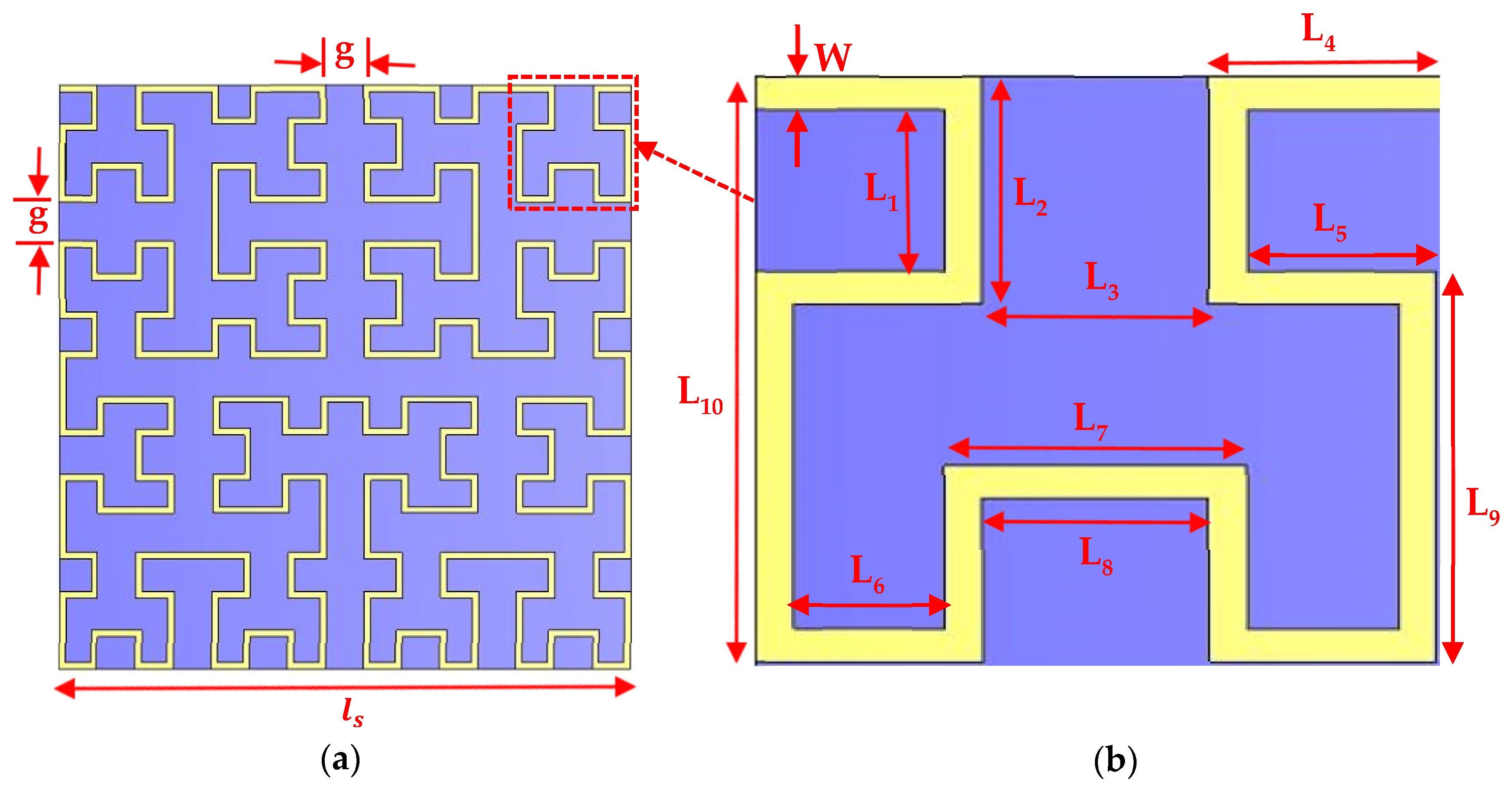
| Parameters | L1 | L2 | L3 | L4 | L5 | L6 | L7 | L8 | L9 | L10 | W | g | ||
|---|---|---|---|---|---|---|---|---|---|---|---|---|---|---|
| Dimension (µm) | 25 | 35 | 30 | 30 | 25 | 20 | 40 | 30 | 60 | 90 | 5 | 30 | 450 | 7650 |
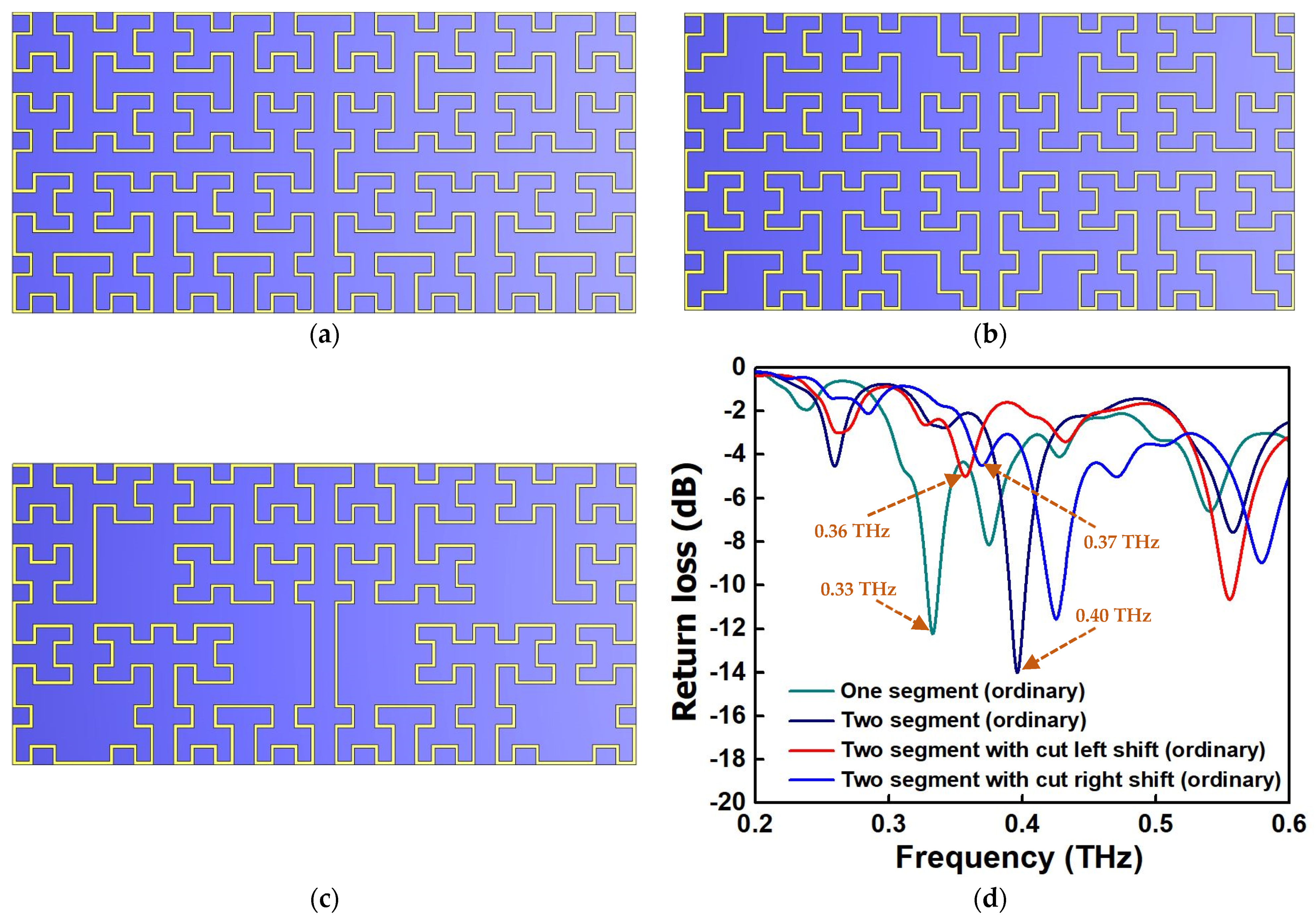
| Design Name | Resonant Frequency (fc) (THz) | Return Loss (dB) | Gain (dBi) | Directivity (dBi) | |
|---|---|---|---|---|---|
| One segment | Ordinary state | 0.54 | −6.61 | 1.73 | 7.35 |
| Extra ordinary state | 0.504 | −14.5 | 4.29 | 8.43 | |
| Two segment (without arm cut) | 0.558 | −8.07 | 0.981 | 5.9 | |
| Two segment (large electrical length) | 0.555 | −10.7 | 2.09 | 7.22 | |
| Two segment (small electrical length) | 0.579 | −9.4 | 2.42 | 7.21 | |
Publisher’s Note: MDPI stays neutral with regard to jurisdictional claims in published maps and institutional affiliations. |
© 2022 by the authors. Licensee MDPI, Basel, Switzerland. This article is an open access article distributed under the terms and conditions of the Creative Commons Attribution (CC BY) license (https://creativecommons.org/licenses/by/4.0/).
Share and Cite
Garu, P.; Wang, W.-C. Design and Analysis of a PDLC-Based Reconfigurable Hilbert Fractal Antenna for Large and Fine THz Frequency Tuning. Micromachines 2022, 13, 964. https://doi.org/10.3390/mi13060964
Garu P, Wang W-C. Design and Analysis of a PDLC-Based Reconfigurable Hilbert Fractal Antenna for Large and Fine THz Frequency Tuning. Micromachines. 2022; 13(6):964. https://doi.org/10.3390/mi13060964
Chicago/Turabian StyleGaru, Prabir, and Wei-Chih Wang. 2022. "Design and Analysis of a PDLC-Based Reconfigurable Hilbert Fractal Antenna for Large and Fine THz Frequency Tuning" Micromachines 13, no. 6: 964. https://doi.org/10.3390/mi13060964