
Structural Design and Analysis of Hybrid Drive Multi-Degree-of-Freedom Motor


Abstract
:1. Introduction
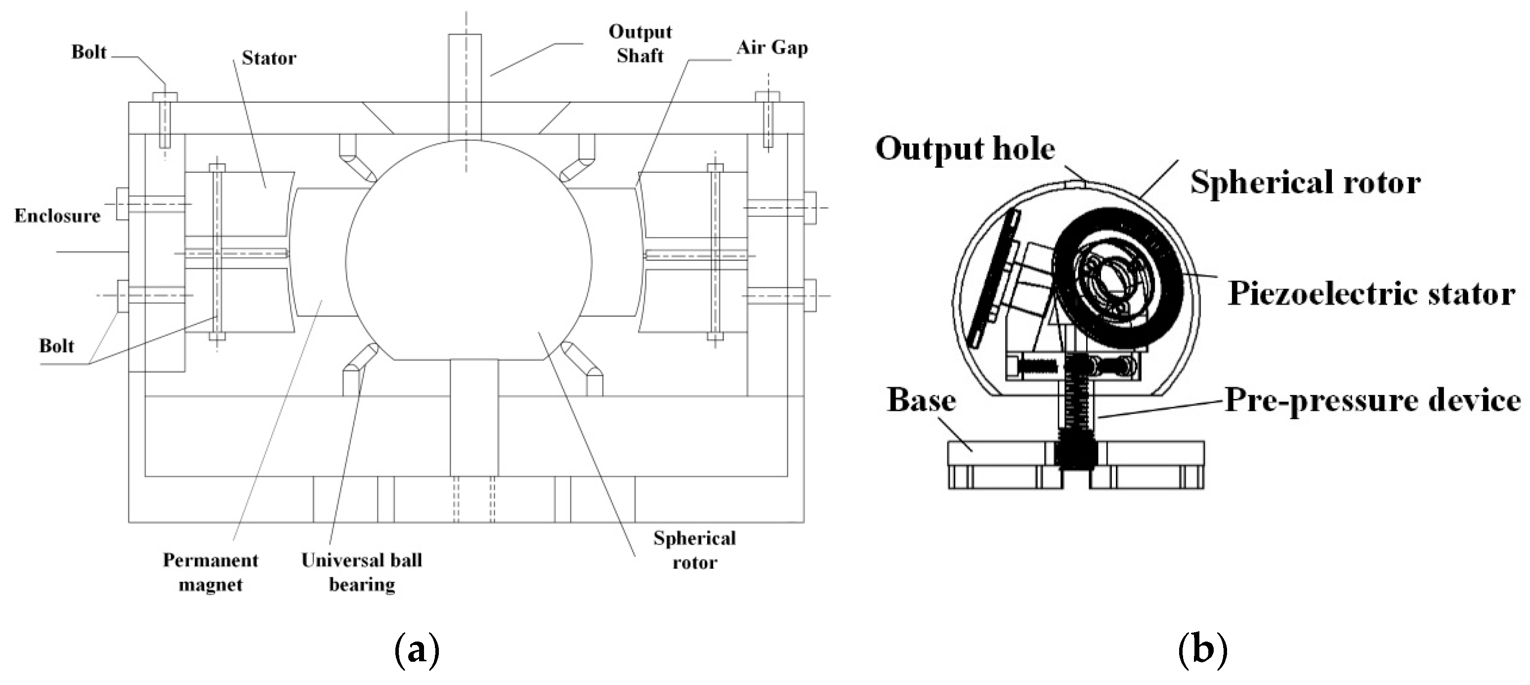
2. Structure and Working Principle
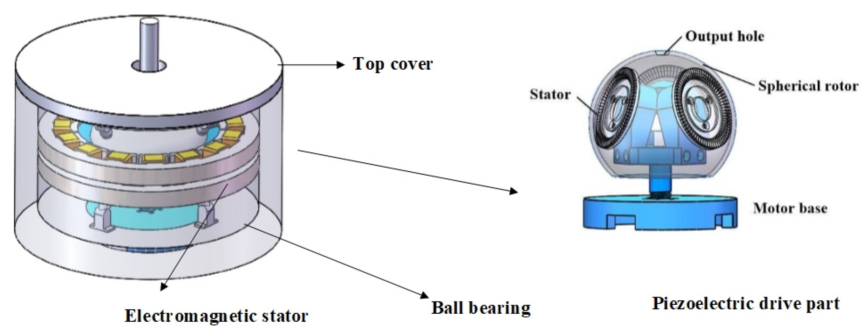
2.1. Hybrid Drive Motor Structure
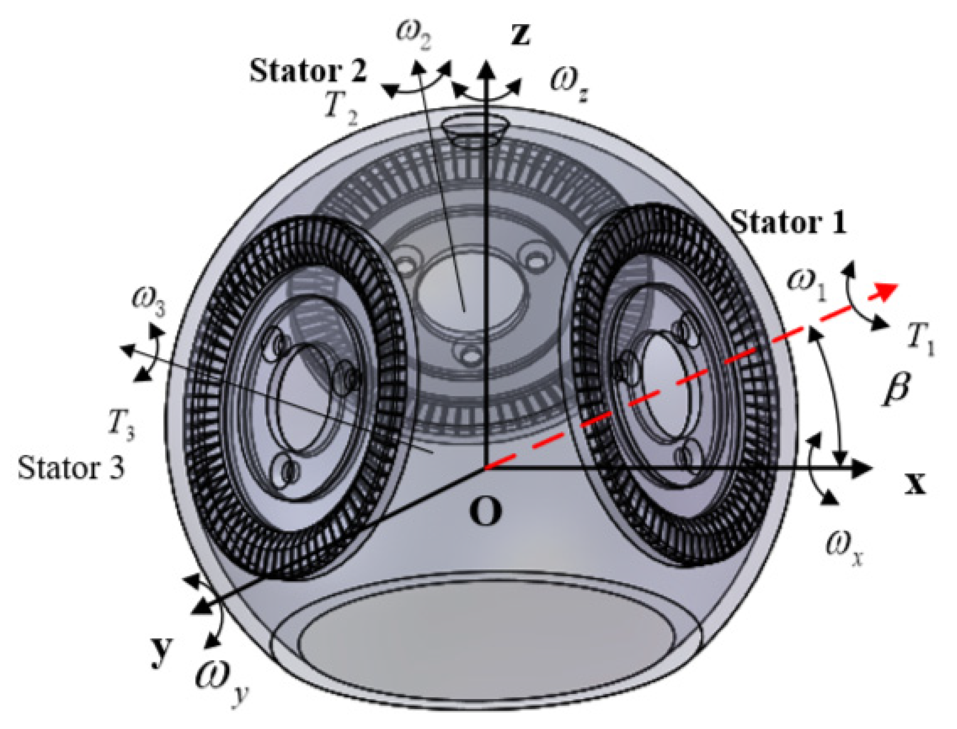
2.2. Working Principle
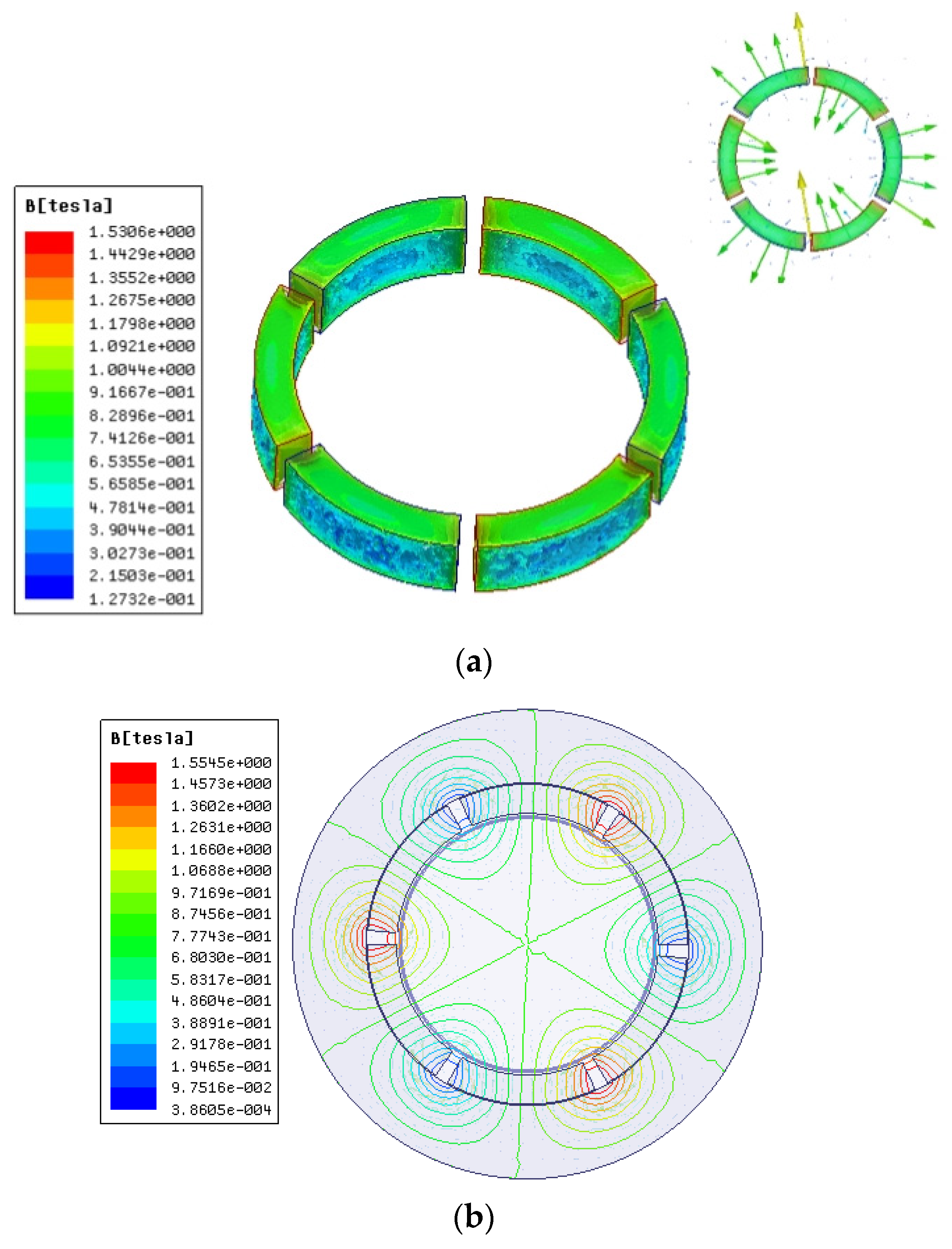
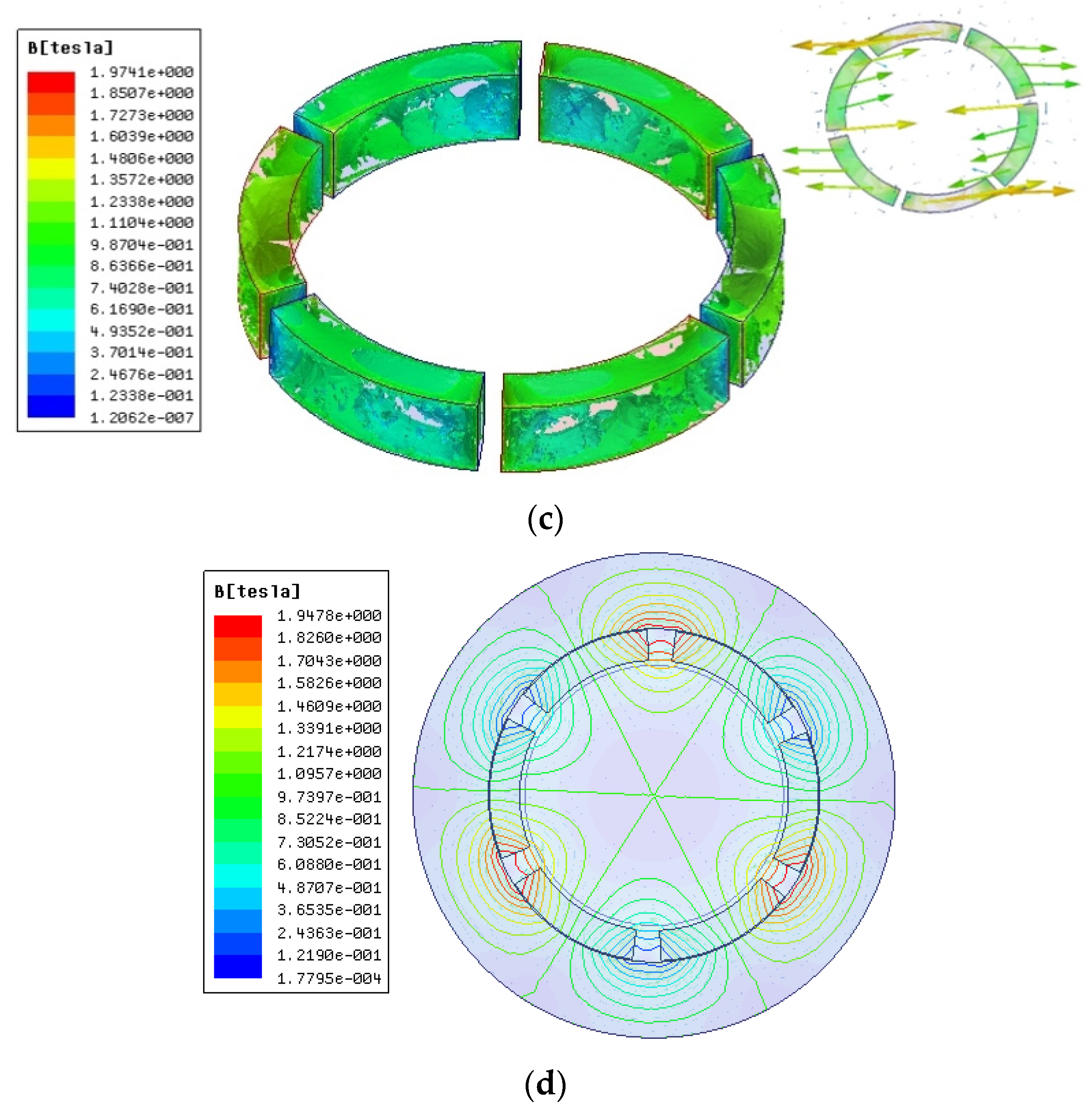
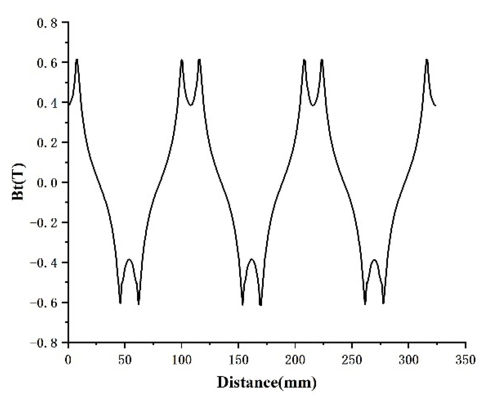
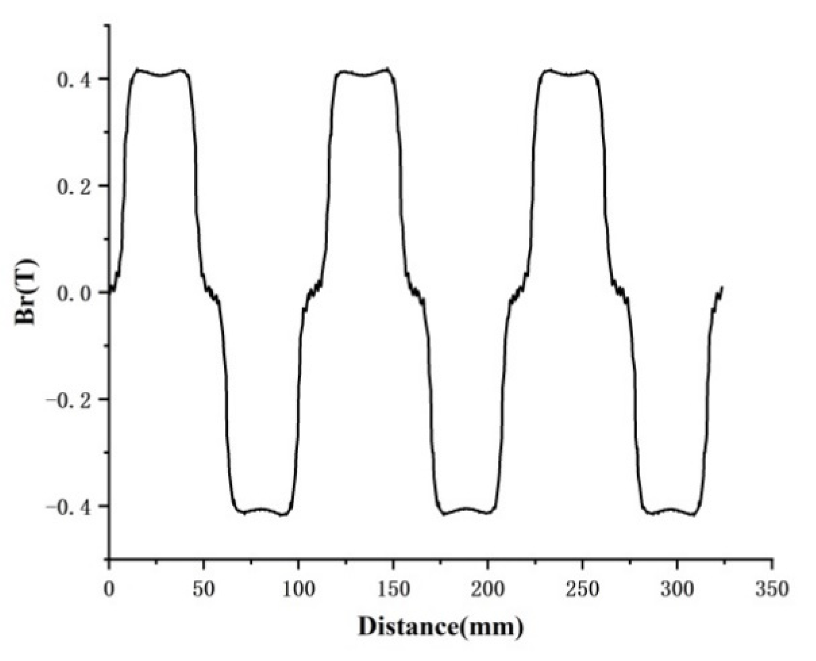
3. Analysis of Air Gap Magnetic Density
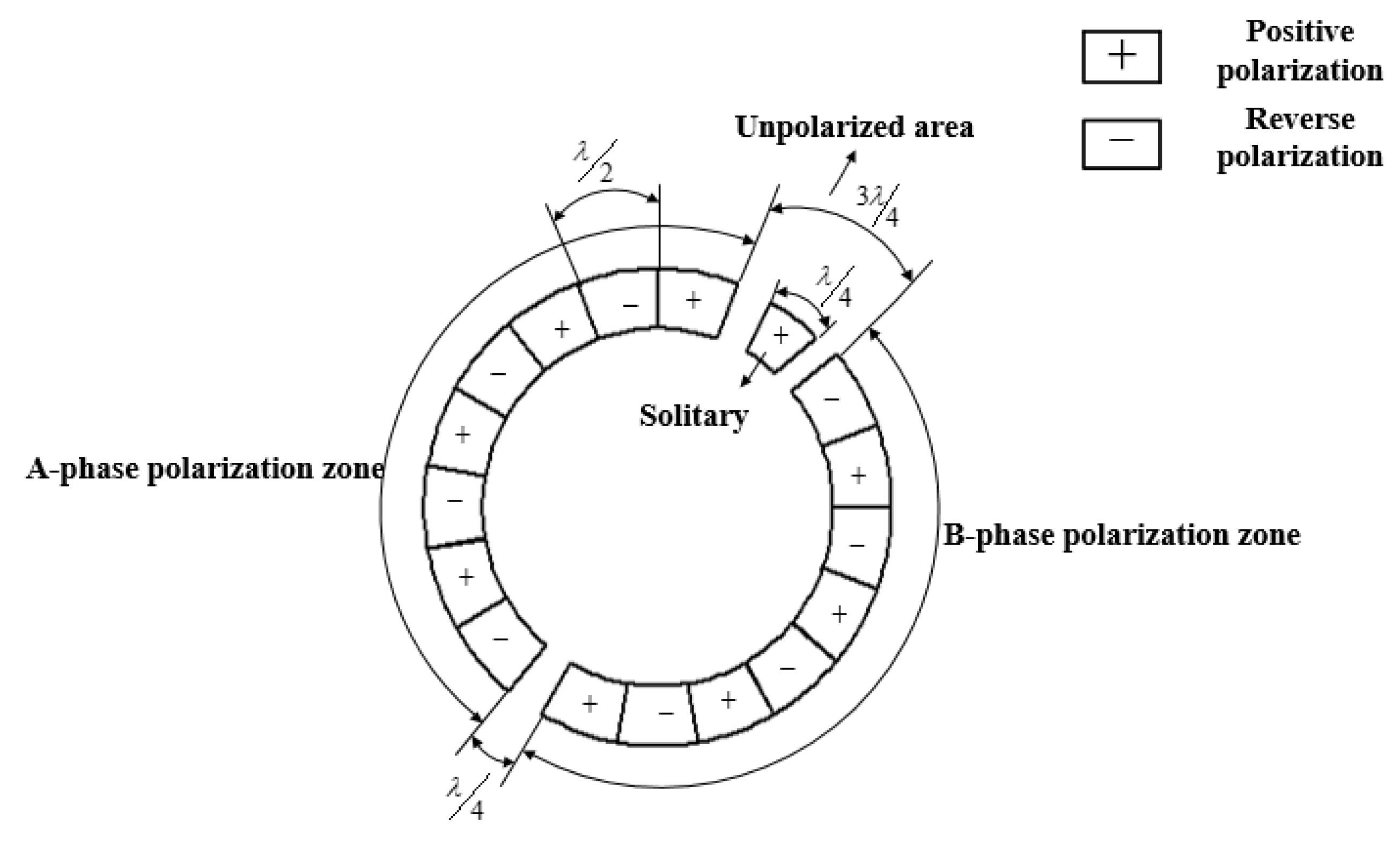
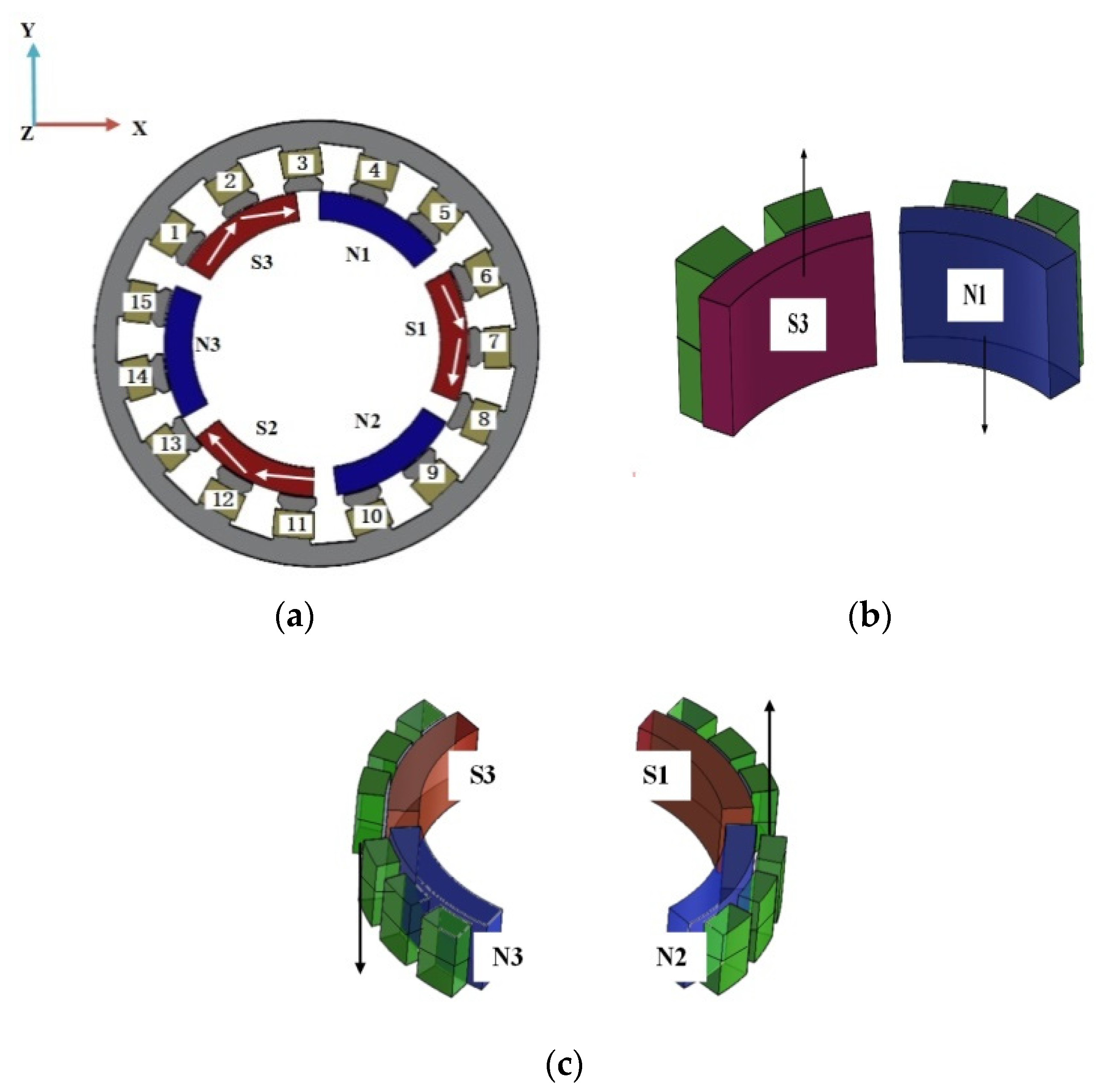
3.1. Magnetization Method
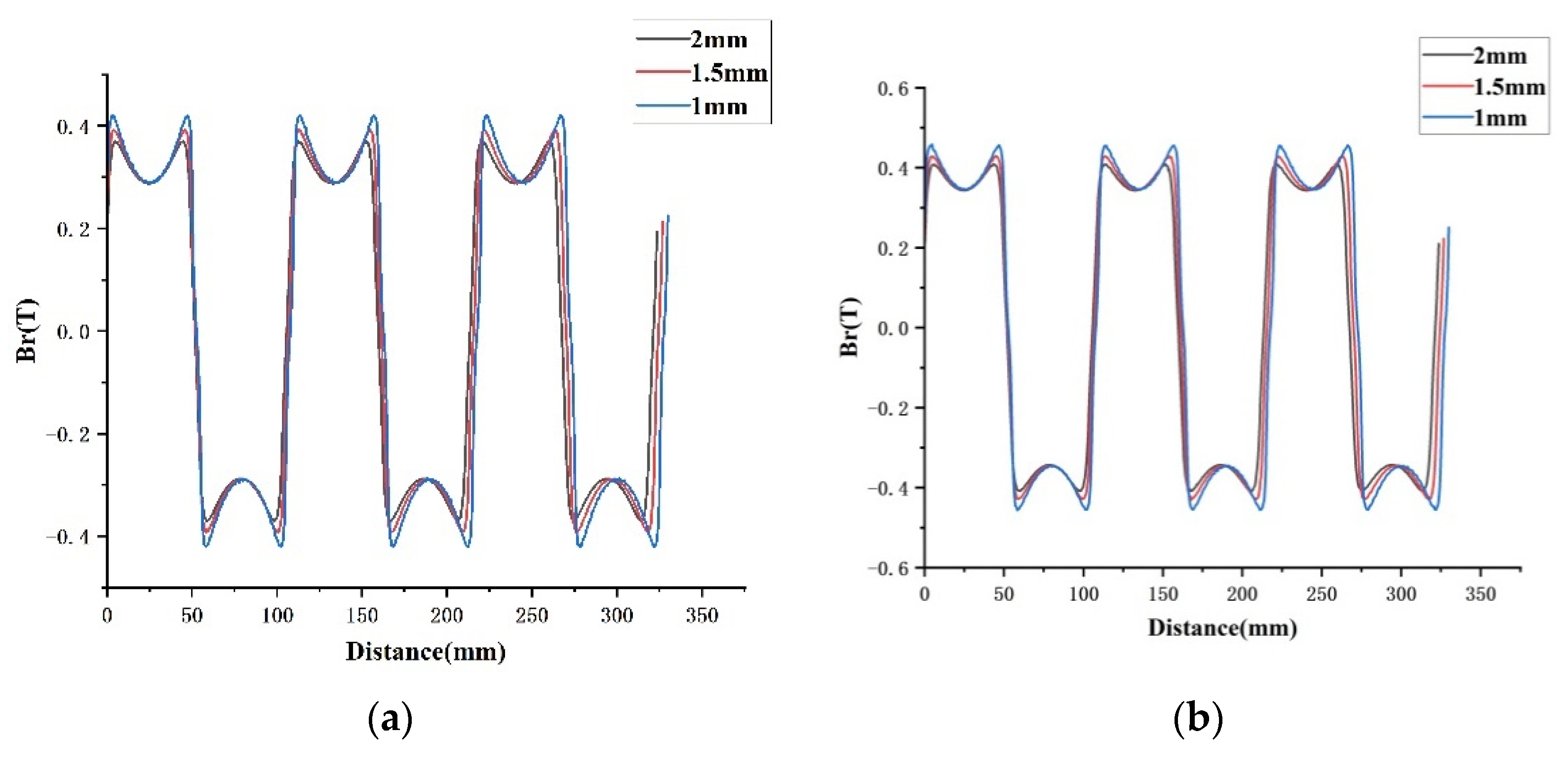
3.2. Effect of Permanent Magnet Thickness
4. Alveolar Torque
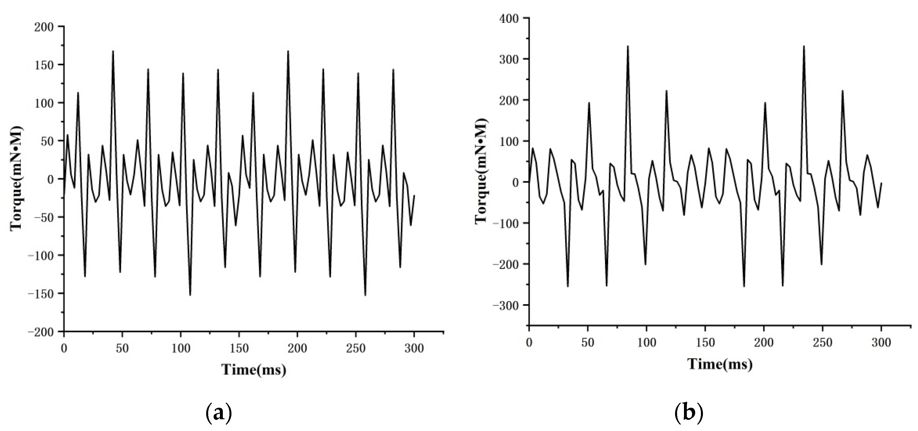
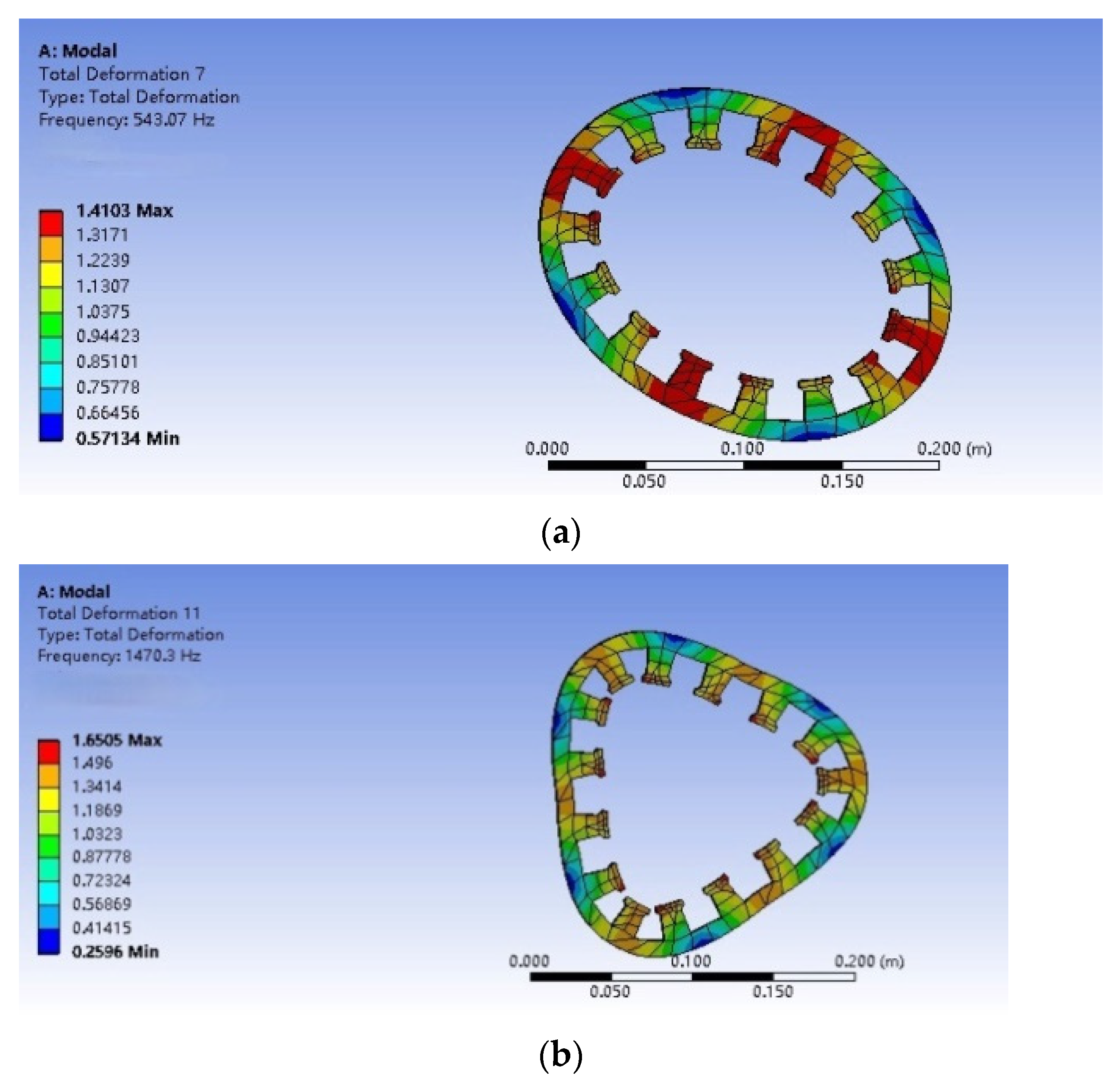
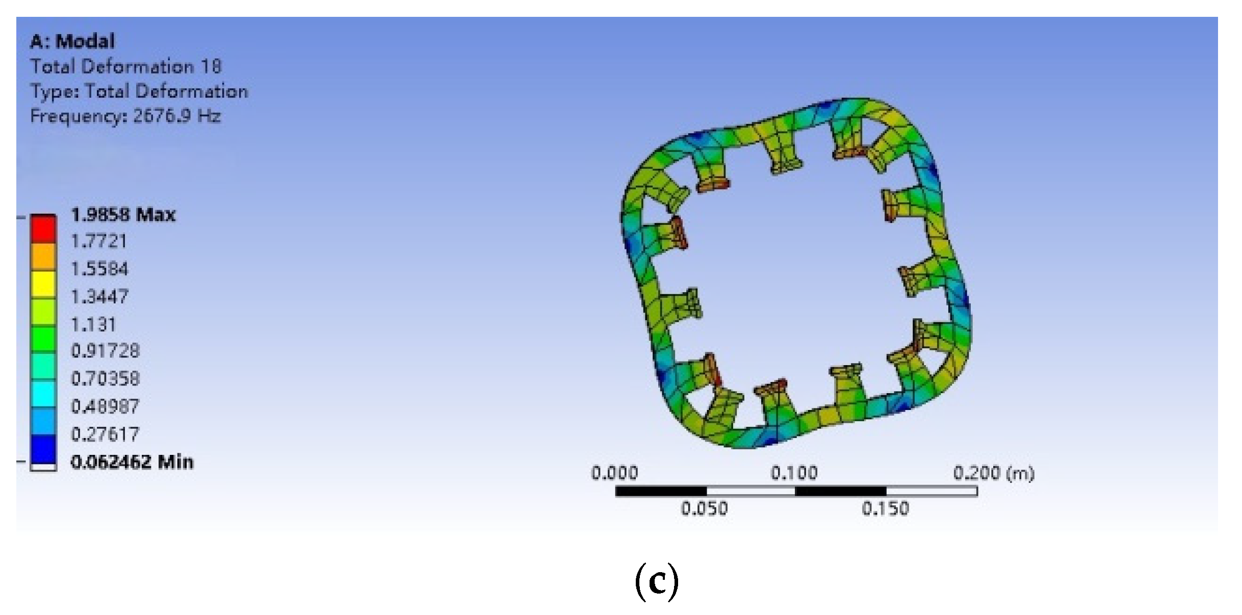
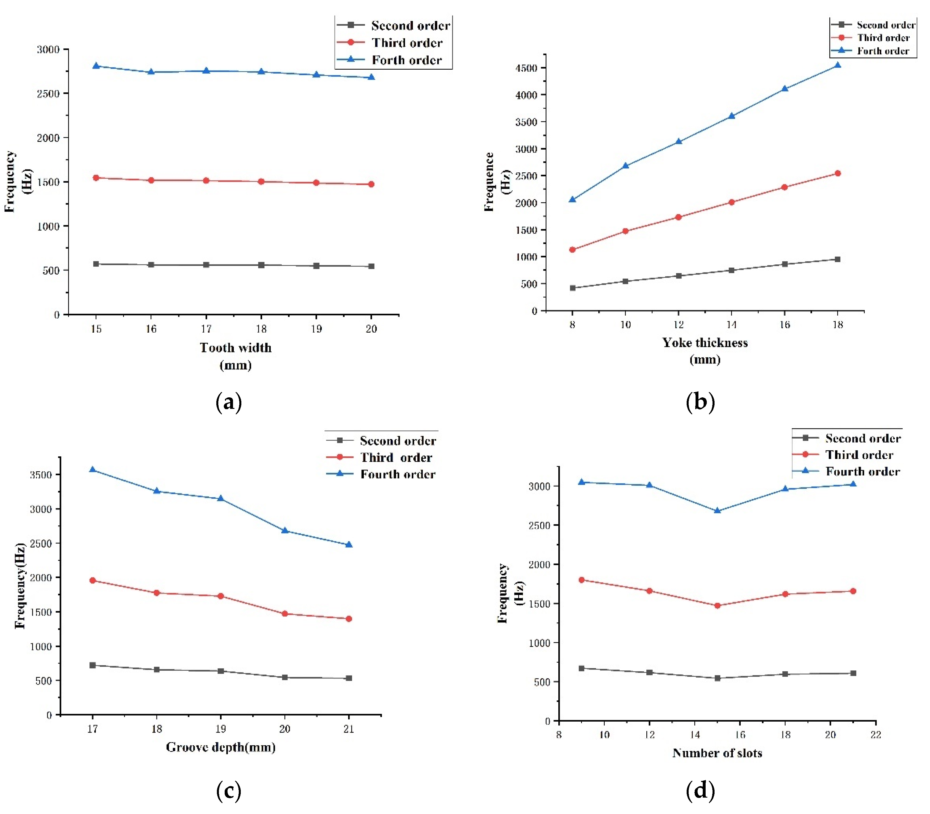
5. Stator Mode
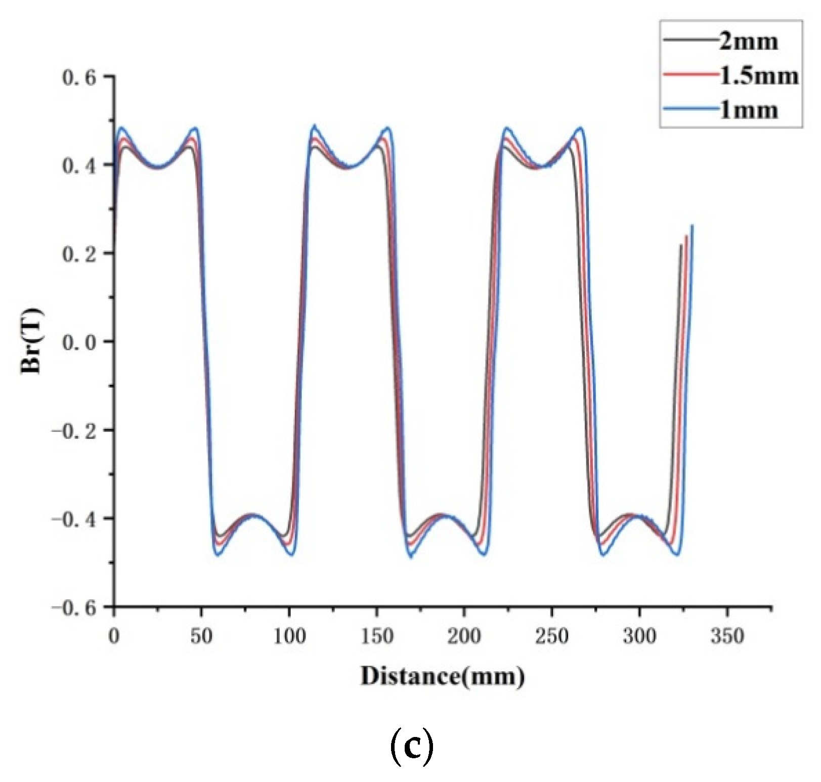
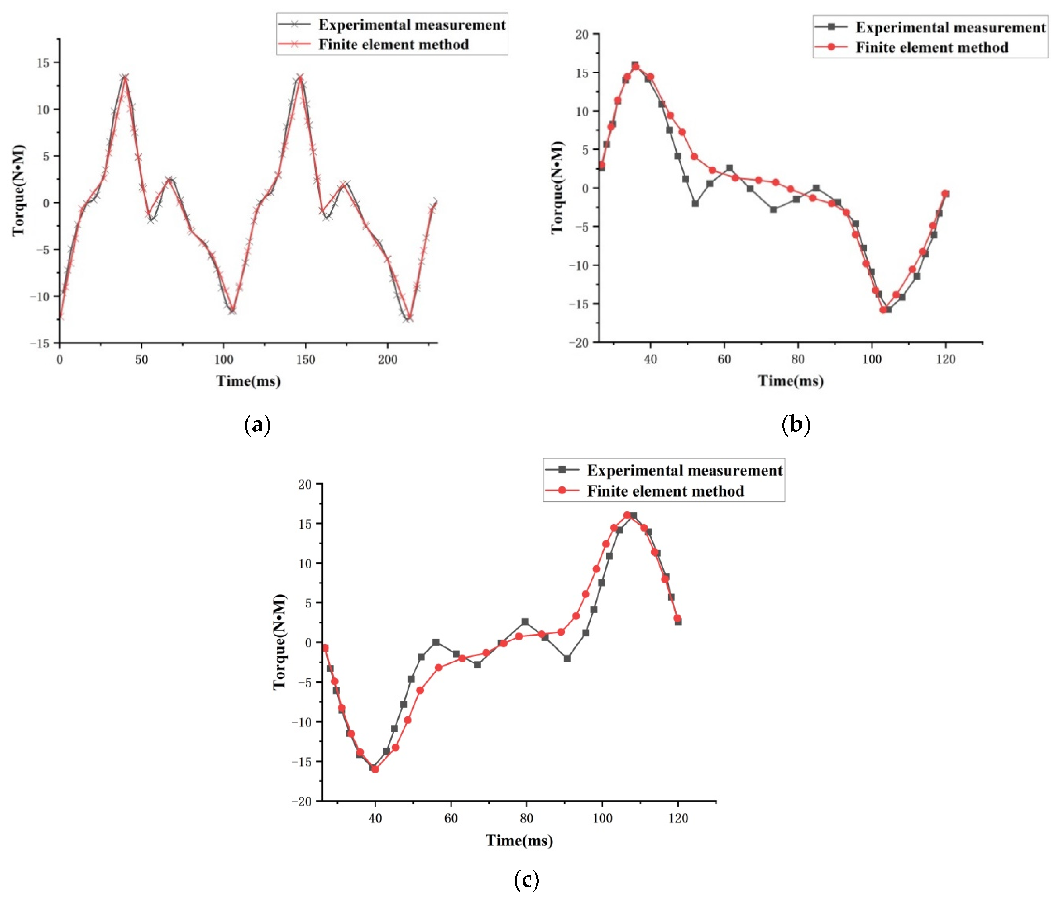
6. Motor Torque Analysis
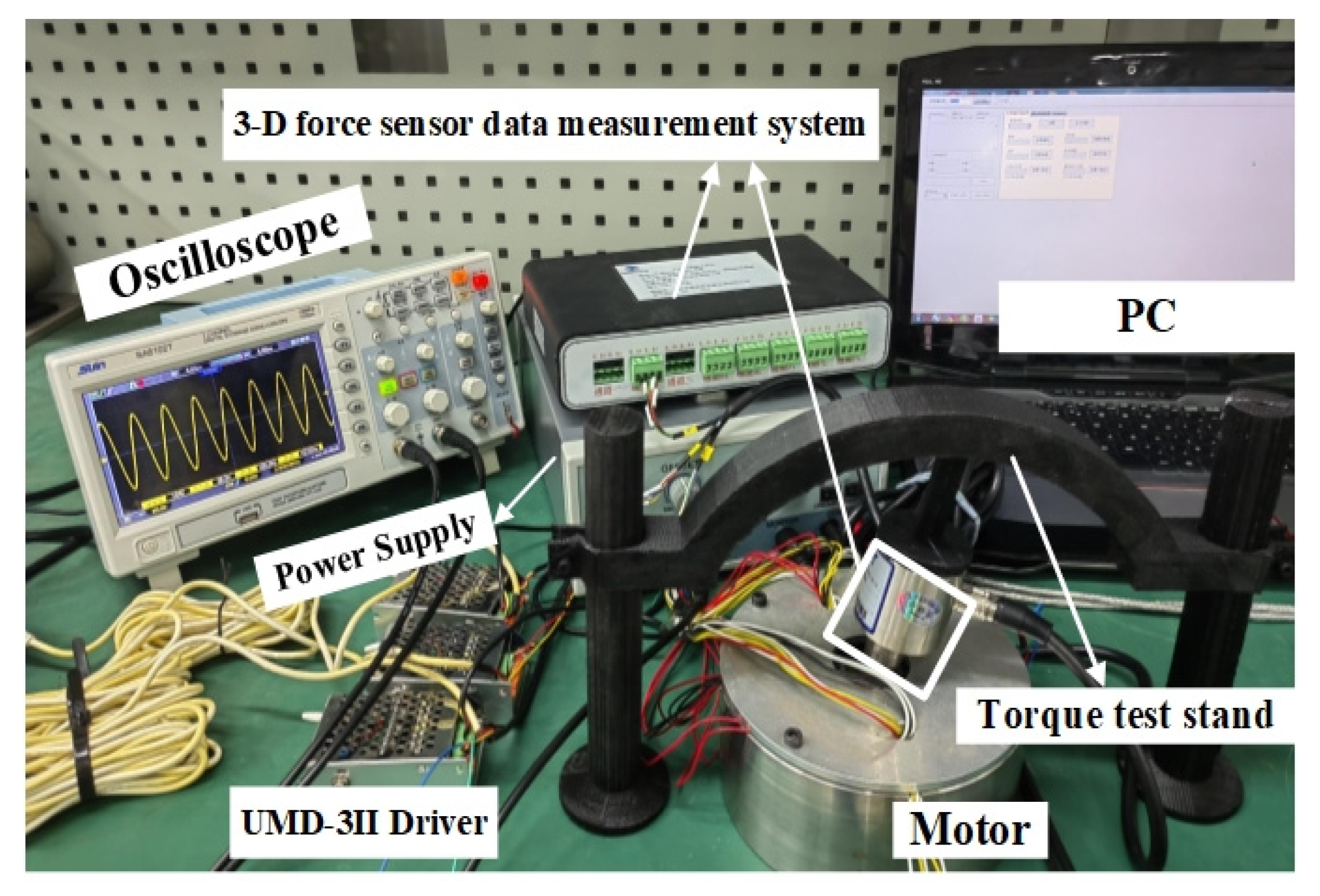
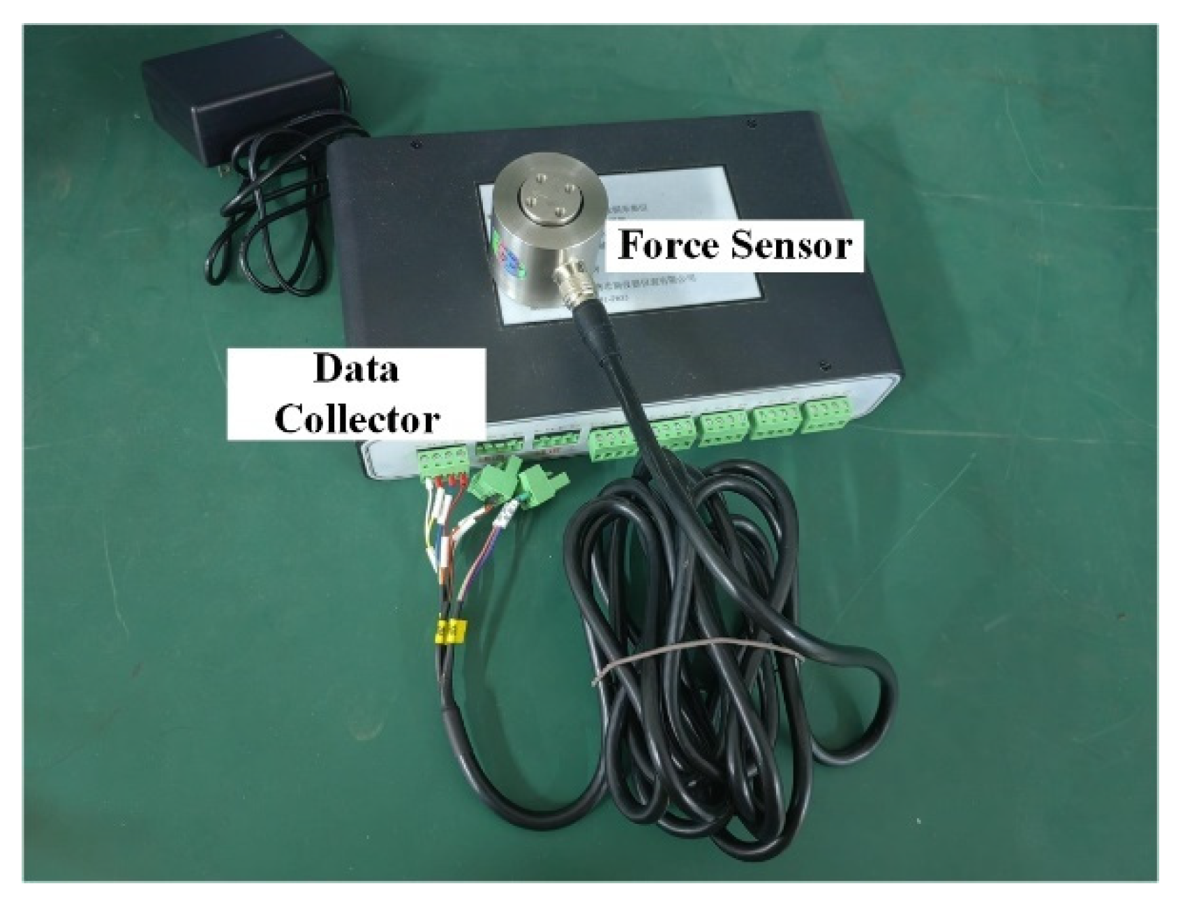
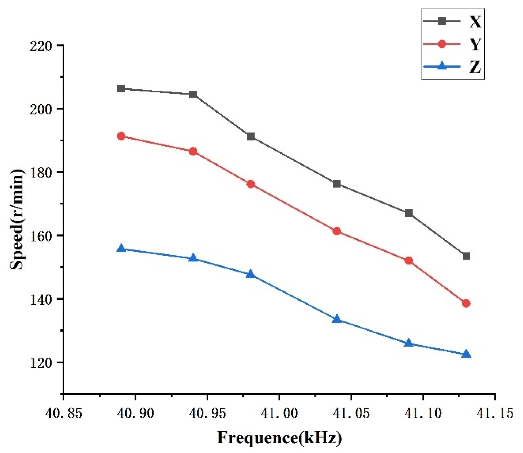
7. Experiment
8. Conclusions
Author Contributions
Funding
Conflicts of Interest
References
- Wang, J.; Mitchell, K.; Jewell, G.; Howe, D. Multi-degree-of-freedom spherical permanent magnet motors. In Proceedings of the IEEE International Conference on Robotics & Automation, Seoul, Korea, 21–26 May 2001. [Google Scholar]
- Li, X.; Liu, J.; Chen, W.; Bai, S. Integrated design, modeling and analysis of a novel spherical motion generator driven by electromagnetic principle. Robot. Auton. Syst. 2018, 106, 69–81. [Google Scholar] [CrossRef]
- Zhang, X.; Zhang, G.; Nakamura, K.; Ueha, S. A robot finger joint driven by hybrid multi-dof piezoelectric ultrasonic motor. Sens. Actuators A Phys. 2011, 169, 206–210. [Google Scholar] [CrossRef]
- Huang, K.; Wu, C.; Hwu, E. Design and development of multi-dof ball-type micromotor. IFAC Proc. Vol. 2006, 39, 908–913. [Google Scholar] [CrossRef]
- Lin, H.; Xu, B.; Chen, T.; Liu, H.; Huang, H.; Sun, L.; Cui, L. Design of a hybrid piezoelectric-electromagnetic vibration power generator power generator. In Proceedings of the IEEE International Conference on Nanotechnology, Sendai, Japan, 22–25 August 2016. [Google Scholar]
- Okeya, R.; Aoyagi, M.; Takano, T.; Tamura, H. Development of electromagnetic and piezoelectric hybrid actuator system. Sens. Actuators A Phys. 2013, 200, 155–161. [Google Scholar] [CrossRef] [Green Version]
- Shi, S.; Xiong, H.; Liu, Y.; Chen, W.; Liu, J. A ring-type multi-dof ultrasonic motor with four feet driving consistently. Ultrasonics 2017, 76, 234–244. [Google Scholar] [CrossRef] [PubMed]
- Yang, X.; Liu, Y.; Chen, W.; Liu, J. Sandwich-type multi-degree-of-freedom ultrasonic motor with hybrid excitation. IEEE Access 2016, 4, 1. [Google Scholar] [CrossRef]
- Li, Z.; Zhao, H.; Che, S.; Chen, X.; Sun, H. Analysis of Preload of Three-Stator Ultrasonic Motor. Micromachines 2021, 13, 5. [Google Scholar] [CrossRef] [PubMed]
- Li, Z.; Guo, P.; Han, R.; Wang, Q. Torque modeling and characteristic analysis of electromagnetic piezoelectric hybrid-driven 3-degree-of-freedom motor. Adv. Mech. Eng. 2018, 10, 1687814018804743. [Google Scholar] [CrossRef] [Green Version]
- Li, Y.; Guo, Z.; Zhang, Q.; Peng, B. Performance comparison between axial flux and radial flux permanent synchronous generator. Small Spec. Electr. Mach. 2021, 49, 8–13. [Google Scholar]
- Qiu, H.; Yu, W.; Li, Y.; Yang, C. Research on the influence of driving harmonic on electromagnetic field and temperature field of permanent magnet synchronous motor. Arch. Electr. Eng. 2017, 66, 295–312. [Google Scholar] [CrossRef] [Green Version]
- Li, X.; Zhang, X.; Wang, C.; Xu, Z. Analysis of the Influence of Different Slot Numbers on Simulation Results of Permanent Magnet Motor. Agric. Equip. Veh. Eng. 2020, 58, 1–3. [Google Scholar]
- Huang, Y.; Jiang, L.; Lei, H. Research on cogging torque of the permanent magnet canned motor in domestic heating system. Energy Rep. 2021, 7, 1379–1389. [Google Scholar] [CrossRef]
- Zhang, J.; Feng, G.; Zhang, B.; Li, D. Research on cogging torque weakening of direct-drive permanent magnet motor with inner enhance force. IEEE J. Trans. Electr. Electron. Eng. 2022, 17, 160–168. [Google Scholar] [CrossRef]
- Wang, Z.; Wu, H. Research on torque density maximization of surface mounted sinusoidal pole motor with radial magnetization. Micromotors 2021, 54, 23–27. [Google Scholar]
- Li, Z.; Liu, L. Dynamics analysis and electromagnetic characteristics calculation of permanent magnet 3-degree-of-freedom motor. Sci. Prog. 2019, 103, 003685041987421. [Google Scholar] [CrossRef] [PubMed]
- Ma, G. The Modal Analysis, Equivalent and Analytical Calculation of the Stator of Permanent Magnet Synchronous Motor. Master’s Thesis, Shandong University, Shandong, China, 2020. [Google Scholar]
- Areed, N.; Marwa, H.; Obayya, S. Reconfigurable coupler-based metallic photonic crystal lens and nematic liquid crystal. J. Opt. Soc. Am. B 2018, 35, 2459. [Google Scholar] [CrossRef]
- Zeng, L.; Wang, J.; Zhang, D. Mechanism and suspension control study for spherical reluctance motor with magnetic levitation. Adv. Mater. Res. 2012, 915–916, 400–406. [Google Scholar] [CrossRef]
- Chen, L.; Li, Y.; Shen, N.; Hui, X. Three-dimensional temperature and stress field simulation with all-hexahedral element mesh in a high efficiency cooling structure for the fabrication of amorphous ribbons. Mater. Res. Express 2022, 9, 036101. [Google Scholar] [CrossRef]
- Konz, M.; Chiari, M.; Rimkus, S.; Turowski, J.; Molnar, P.; Rickenmann, D. Sediment transport modelling in a distributed physically based hydrological catchment model. Hydrol. Earth Syst. Sci. 2011, 15, 2821–2837. [Google Scholar] [CrossRef]
- Zhao, H.; Yu, S. Design of rotor and permanent magnet of low speed and high torque permanent magnet synchronous motor. Res. Des. 2021, 32, 24–26+50. [Google Scholar]
- Mao, T. Research on Bionic Soft Robots with Hybrid Piezoelectric-SMA Actuation. Master’s Thesis, Nanjing University of Aeronautics and Astronautics, Nanjing, China, 2020. [Google Scholar]


| Electromagnetic Stator | Permanent Magnet | ||
|---|---|---|---|
| Stator outer diameter | 132 mm | Height | 22.5 mm |
| Stator inner diameter | 192 mm | Thickness | 12 mm |
| Single-layer stator height | 15 mm | Air gap spacing | 0.5 mm |
| Two-layer stator spacing | 6 mm | Corresponding angle | 51° |
| Density | Elastic Modulus | Shear Modulus | Poisson Ratio |
|---|---|---|---|
| 7600 kg/m3 | EX = EY = 195 GPa | GXZ = GYZ = 76.9 GPa | 0.3 |
| EZ = 90 GPa | GXY = 34.6 GPa |
Publisher’s Note: MDPI stays neutral with regard to jurisdictional claims in published maps and institutional affiliations. |
© 2022 by the authors. Licensee MDPI, Basel, Switzerland. This article is an open access article distributed under the terms and conditions of the Creative Commons Attribution (CC BY) license (https://creativecommons.org/licenses/by/4.0/).
Share and Cite
Li, Z.; Zhao, H.; Chen, X.; Du, S.; Guo, X.; Sun, H. Structural Design and Analysis of Hybrid Drive Multi-Degree-of-Freedom Motor. Micromachines 2022, 13, 955. https://doi.org/10.3390/mi13060955
Li Z, Zhao H, Chen X, Du S, Guo X, Sun H. Structural Design and Analysis of Hybrid Drive Multi-Degree-of-Freedom Motor. Micromachines. 2022; 13(6):955. https://doi.org/10.3390/mi13060955
Chicago/Turabian StyleLi, Zheng, Hui Zhao, Xuetong Chen, Shenhui Du, Xiaoqiang Guo, and Hexu Sun. 2022. "Structural Design and Analysis of Hybrid Drive Multi-Degree-of-Freedom Motor" Micromachines 13, no. 6: 955. https://doi.org/10.3390/mi13060955