Article

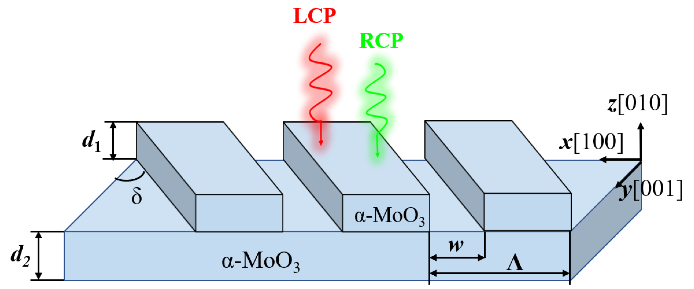
Metasurfaces Assisted Twisted α-MoO3 for Spinning Thermal Radiation

1
Basic Research Center, School of Power and Energy, Northwestern Polytechnical University, Xi’an 710072, China
2
Center of Computational Physics and Energy Science, Yangtze River Delta Research Institute of NPU, Northwestern Polytechnical University, Taicang 215400, China
3
Shandong Institute of Advanced Technology, Jinan 250100, China
4
School of Energy Science and Engineering, Harbin Institute of Technology, Harbin 150001, China
5
Centre for Advanced Laser Manufacturing (CALM), School of Mechanical Engineering, Shandong University of Technology, Zibo 255000, China
*
Author to whom correspondence should be addressed.
Micromachines 2022, 13(10), 1757; https://doi.org/10.3390/mi13101757
Submission received: 5 September 2022 / Revised: 14 October 2022 / Accepted: 15 October 2022 / Published: 17 October 2022
(This article belongs to the Special Issue Integrated Photonics and Optoelectronics)

Abstract

:
Spinning thermal radiation has demonstrated applications in engineering, such as radiation detection and biosensing. In this paper, we propose a new spin thermal radiation emitter composed of the twisted bilayer α-MoO3 metasurface; in our study, it provided more degrees of freedom to control circular dichroism by artificially modifying the filling factor of the metasurface. In addition, circular dichroism was significantly enhanced by introducing a new degree of freedom (filling factor), with a value that could reach 0.9. Strong-spin thermal radiation resulted from the polarization conversion of circularly polarized waves using the α-MoO3 metasurface and selective transmission of linearly polarized waves by the substrate. This allowed for extra flexible control of spinning thermal radiation and significantly enhanced circular dichroism, which promises applications in biosensing and radiation detection. As a result of their unique properties, hyperbolic materials have applications not only in spin thermal radiation, but also in areas such as near-field thermal radiation. In this study, hyperbolic materials were combined with metasurfaces to offer a new idea regarding modulating near-field radiative heat transfer.

1. Introduction

In recent years, thermal radiation has attracted considerable attention from researchers due to its high potential for applications in areas such as energy harvesting [1,2,3,4] and coherent heat sources [5,6,7]. According to wave-particle duality, the nature of thermal radiation is electromagnetic waves. Therefore, thermal radiation possesses various properties of electromagnetic waves, such as superposition and coherence properties, spectral properties and polarization properties [8,9,10]. Greffet et al. demonstrated that periodic microstructures could emit a coherent and linearly polarized wave [5], which offers significant promise for controlling the spectral, coherent and polarization properties of thermal radiation [11,12,13]. Spin polarized (circularly polarized) wave has gained extensive attention in chiral optics [14,15,16] and spin-controlled nanophotonics [17,18,19]; spin angular momentum is used to engineer spin-dependent nanoscale light-matter interactions. Recently, studies regarding chiral microstructures have demonstrated the feasibility of spin thermal radiation for engineering, including thermal detection [20,21,22].
In general, spin thermal radiation can be generated by breaking rotational symmetry and mirror symmetry simultaneously. Circular dichroism (CD) is defined as the difference in the absorption between left-hand circular polarization (LCP) and right-hand circular polarization (RCP); CD is an important parameter when measuring spin thermal radiation [21,22]. At present, many approaches have been proposed to improve CD [23,24]. It is possible to break mirror symmetry using an applied magnetic field (due to the spin-orbit interaction of electrons) resulting in spin thermal radiation [25]. Nevertheless, this approach requires additional incentives and is not conducive to practical application.
Hyperbolic materials (HMs) have attracted much attention due to their unique properties [26,27]. HMs have a wide range of promising applications in broadband enhanced local density of states (LDOS) [28], spontaneous emission [29,30,31], hyperbolic lensing [32,33,34], negative refraction [35,36], super absorption [37] and Förster energy transfer [38,39,40]. As a natural biaxial hyperbolic crystal with in-plane anisotropy, α-MoO3 has a unique advantage in exciting spin thermal radiation. Hexagonal boron nitride (hBN) is another hyperbolic material with out-of-plane anisotropy, which is also capable of exciting spin thermal radiation. Generally, spin thermal radiation requires more anisotropy. Compared to the uniaxial hyperbolic material hBN, α-MoO3 is a natural biaxially hyperbolic material with both in-plane and out-of-plane anisotropy, enabling it to facilitate spin thermal radiation. In addition, α-MoO3 has a wider hyperbolic band, carrying larger electromagnetic wave energy, which offers the possibility of enhancing circular dichroism. [41]. Wu et al. studied the spin thermal radiation properties of single-layer α-MoO3 [42] and double-layer twisted α-MoO3 structures [43]. Although the structures mentioned above can excite spin thermal radiation properties, the CD obtained by optimizing the rotation angle and thickness parameters was always very limited.
Another way to achieve spin thermal radiation is to create a structure with chiral surface morphology or with the help of chiral metamaterials. Dyakov et al. proposed a photonic crystal slab waveguide with chiral morphology that can excite spin thermal radiation without an external magnetic field [44]. Kong et al. proposed a novel chiral metamaterial structure with Γ-shaped aligned nanocrystals to achieve significant CD [24]. To date, many two-dimensional (2D) or three-dimensional (3D) chiral microstructures have been designed that enhance spin thermal radiation significantly [45,46]. Although chiral metamaterials can effectively improve CD, subwavelength nanostructures tend to increase the complexity of structural fabrication. Metasurfaces, as two-dimensional derivatives of metamaterials composed of a single or a few patterned layer planar structures, reduce the fabrication requirement. In recent years, metasurfaces have attracted much attention from researchers and have a high potential for important applications [47,48]. More importantly, thermal radiation devices based on metasurfaces possess more freedom of regulation. Recently, metasurfaces based on α-MoO3 rectangular strips, which only need to be etched on a single layer of slab, have attracted interest. Huang et al. [49] studied hyperbolic phonon polarization excitons (HPhPs) of van der Waals semiconductors coupled to terahertz and LWIR radiation based on gratings etched directly on α-MoO3 semiconductor flat plates, ultimately obtaining quality factors as high as 300. However, the spin thermal radiation of α-MoO3 microstructures is still seldom studied.
This paper describes our study of the spin thermal radiation properties of the metasurface-assisted twisted bilayer α-MoO3. First, the effects of the thicknesses of the two layers and the rotation angle on the CD value were investigated. In addition, a new degree of freedom (filling factor) was introduced. It was found that the structure can greatly enhance spin thermal radiation, and also provide more degrees of freedom to control the spin thermal radiation instead of limiting it to a specific angle. Furthermore, this paper explains the physical mechanism of CD dependence on the filling factor from the perspective of polarization conversion. This study achieved strong spin thermal radiation, which allows greater freedom in tuning the spin thermal radiation.

2. Theory and Method

Figure 1 shows the proposed metasurface structure, which consists of a periodic α-MoO3 rectangular strip and an α-MoO3 substrate. As shown in Figure 1, d1 and d2 represent the thicknesses of rectangular strips and substrate, respectively. δ represents the relative rotation angle between the rectangular strips and the substrate. When the rectangular strips had a rotation angle with respect to the substrate, the overall symmetry of the structure broke. w represents the spacing of the rectangular strips, Λ is the period, and the incident light was directed along the z-axis. For the α-MoO3 substrate, the crystal axes [100], [001] and [010] were along the x, y and z directions, respectively. Thus, the permittivity tensor of the α-MoO3 substrate can be denoted by ε = d i a g ( ε x , ε y , ε z ) , where ε x , ε y and ε z can be represented by the Lorentz model as [50]:
ε m = ε , m 1 + ω L O , m 2 ω T O , m 2 ω T O , m 2 ω 2 j ω Γ m
where w is the angular frequency. The values of the other parameters are shown in Table 1 [51].
We first analyzed the top α-MoO3 rectangular strips using the effective medium theory [52]. The effective permittivity can be expressed as:
ε e f f , x x = ( f ε α M o O 3 , x + 1 f ) 1 ε e f f , y y = ε α M o O 3 , y f + 1 f ε e f f , z z = ε α M o O 3 , z f + 1 f
where f is the filling factor and its value is f = w/Λ.
When the top rectangular strips had a rotation angle δ with respect to the substrate, rotation broke the diagonal tensor form of the original dielectric function; the permittivity tensor of α-MoO3 follows the following transformation form [53]:
ε = cos δ sin δ 0 sin δ cos δ 0 0 0 1 ε eff , x x 0 0 0 ε eff , y 0 0 0 ε eff , z cos δ sin δ 0 sin δ cos δ 0 0 0 1
The new permittivity tensor was obtained after the calculation as follows:
ε = ε e f f , x x c o s 2 δ + ε e f f , y y sin 2 δ ε e f f , x x ε e f f , y y sin δ cos δ 0 ε e f f , x x ε e f f , y y sin δ cos δ ε e f f , x x sin 2 δ + ε e f f , y y cos 2 δ 0 0 0 ε e f f , z z
In this study, the transfer matrix method (TMM) was used to calculate the transmission of the above structures [43].
A large area of α-MoO3 flakes was first grown using the physical vapor deposition method. This was then transferred to a silicon substrate and a combination of electron beam lithography and reactive ion etching was used to etch one-dimensional nanoribbons with different periods and angles on the flakes. Electron beam lithography was performed using a Poly (methyl methacrylate) (PMMA) photoresist and ion etching was performed using a mixture of oxygen, argon and CHF3 at 50 W for 10 min, after which we obtained the α-MoO3 1D grating structure [49].

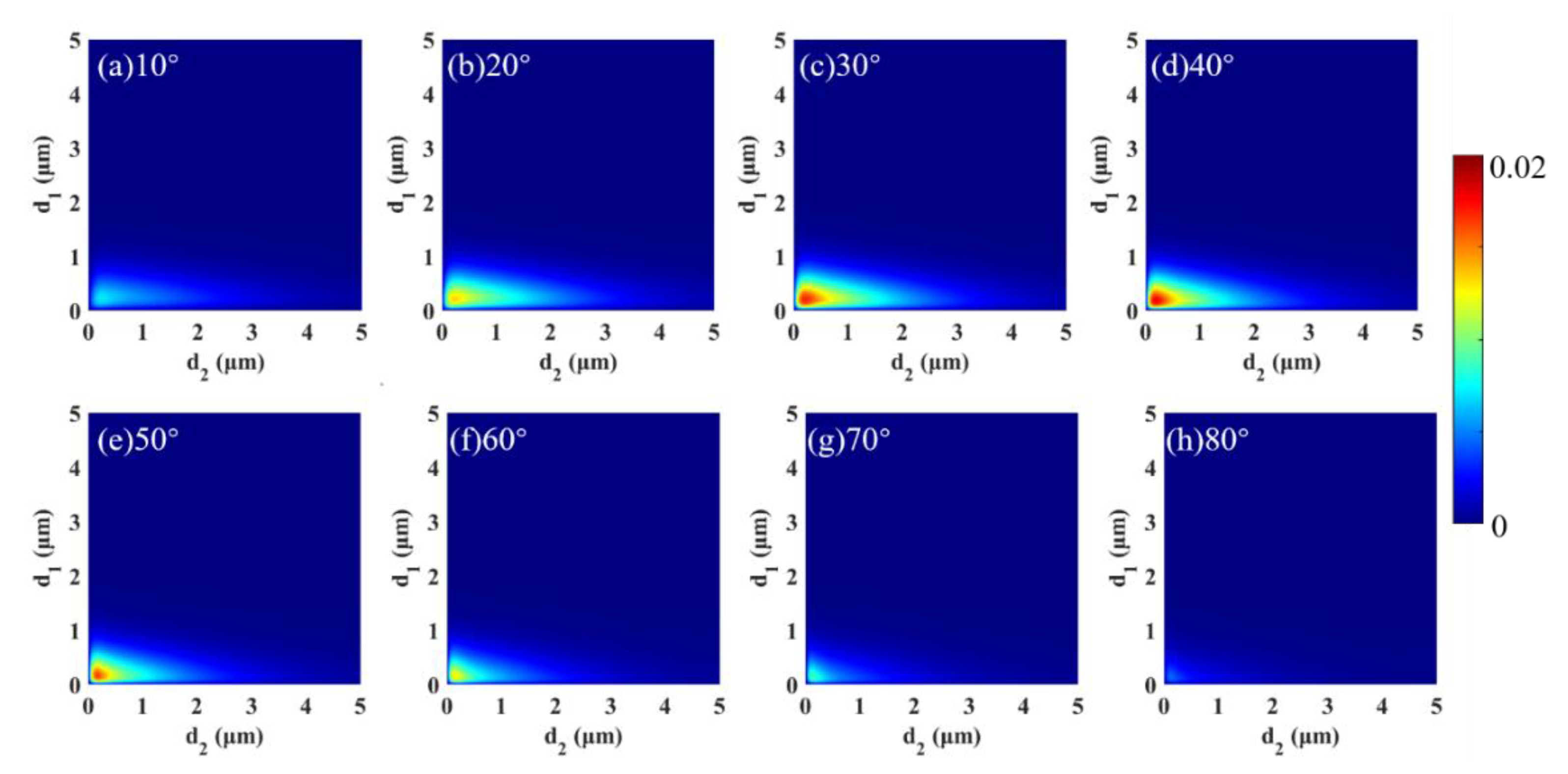
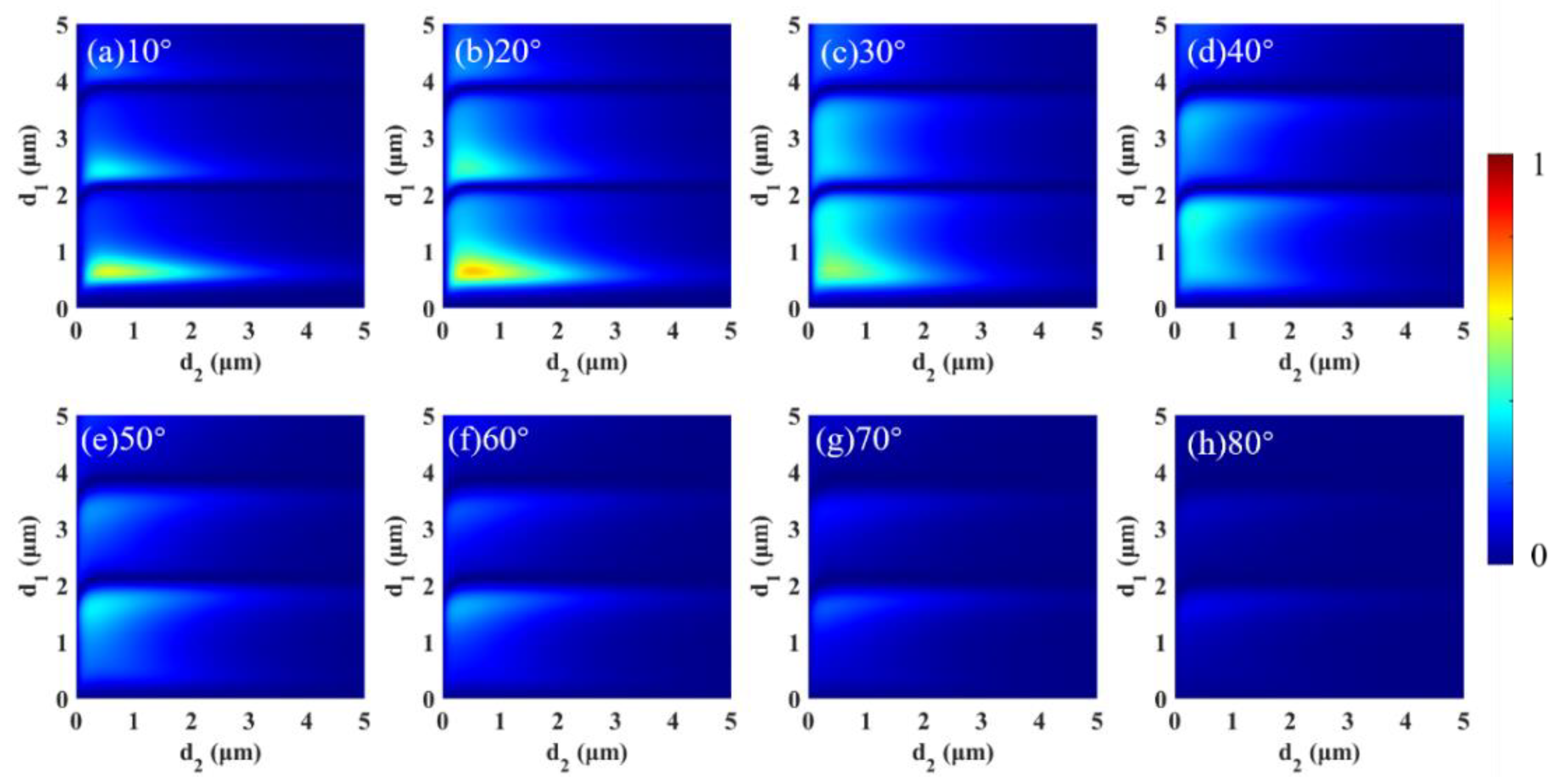
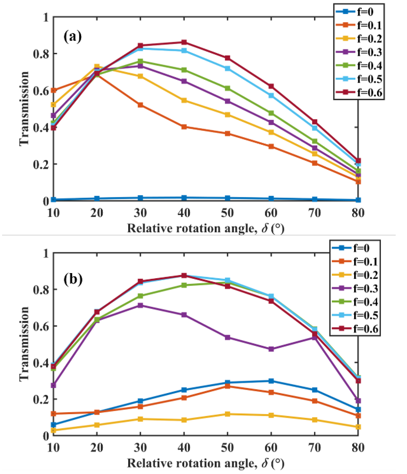
3. Results and Discussion

CD is a key parameter for measuring spin thermal radiation’s radiative properties. In this study, we primarily considered the transmission of the structure. Therefore, CD could be calculated using:
C D = T L C P T R C P ,
where T L C P and T R C P are the transmission of the LCP and RCP waves, respectively.
Based on [44], it is known that the thickness and the relative rotation angle significantly influence the spin radiation properties of the structure. The variation in CD with thickness and the relative rotation angle was first calculated for any wavelength (here, the wavelength was fixed at 12 μm) and f = 0 (bilayer slabs), as shown in Figure 2. The CD value tended to increase and then decrease as the angle of rotation increased. CD reached a maximum value of 0.0178 at d1 = d2 = 0.175 μm. Although CD can be controlled by changing the rotation angle, the CD was still very weak. Results indicate that there was almost no excitation of spin thermal radiation at f = 0; therefore, the bilayer slabs had some limitations regarding exciting spin thermal radiation.
Based on the above study, we introduced the filling factor f. Next, the effect of f on CD is discussed in detail. Here, the wavelength was the same as that in Figure 2. Variation in CD with d1 and d2 as well as the rotation angle are provided in Figure 3. Here, the grating period of the grating was 3 μm. Notably, the maximum value of the color bar is 1, whereas that of Figure 2 is 0.02. Compared to when f = 0, CD has been significantly enhanced. CD could reach 0.6848 at d1 = 0.65 μm, d2 = 0.525 μm and a 20° rotation angle, which is tens of times higher than that at f = 0. The results illustrate that the metasurface structure greatly enhanced spin thermal radiation. In addition, we used the same method to optimize the structure; it was found that CD could reach 0.9 when f = 0.7, d1 = 6.25 μm, d2 = 0.5 μm and δ = 40°, which exceeded the results in previous studies [45,46].
Next, to further illustrate the effect of f on CD, we calculated the variation in the maximum value of CD with the rotation angle when f increased from 0 to 0.6 at every 0.1 interval. Figure 4a,b show results for wavelengths of 12 μm and 11 μm, respectively. In Figure 4a, it can be seen that the overall trend of CD increased with an increase in f, implying that the value of f can enhance the spin thermal radiation in a wide range, which is more beneficial to practical applications. When the wavelength was 11 μm, it can be seen in Figure 4b that, although the CD decreased somewhat at f = 0.1 and f = 0.2, it still showed an overall increasing trend at larger f. We conducted similar studies at other wavelengths, with results similar to those of 12 μm and 11 μm, namely that CD was enhanced as f increased. This suggests that the metasurface structure not only enhances spin thermal radiation, but also has a greater degree of freedom in the excitation of thermal radiation.
To better understand the physical mechanism, we discuss the polarization conversion of circularly polarized waves at a fixed wavelength of 12 µm. Figure 5a shows TE (transverse electric wave) and TM (transverse magnetic wave) components in the transmitted wave varying with the rotation angle for different spin direction circularly polarized waves incidence when f = 0 and d1 = d2 = 0.175 μm. LCP-TM represents the TM wave component in the transmitted wave for LCP wave incidence; RCP-TM, RCP-TE and LCP-TE have similar definitions. When f = 0, the proposed structure can be considered a bilayer slab structure. It can be seen in Figure 5a that regardless of whether LCP or RCP waves were incidents, the TM wave component in the transmitted wave decreased with increasing rotation angle, whereas the TE wave component gradually increased. However, the overall TE wave component was low; therefore, the TM wave component played a major role in spin thermal radiation at this time. Thus, CD mainly originated from the difference in TM wave components in the transmitted waves at the incidence of LCP and RCP waves. Clearly, the difference between TM wave components in the transmitted wave for LCP and RCP incidence was small at any rotation angle. Combined with Figure 4a, it was found that CD was always at a low level at f = 0, which coincides with the result in Figure 5a. The phenomenon in Figure 5b is more obvious in Figure 5a; f = 0.6, d1 = 4.8 μm and d2 = 0.4 μm. TE wave components of LCP and RCP waves were almost zero, whereas the difference in the TM wave components reached a maximum at a rotation angle of 40°, which corresponds almost exactly to when f = 0.6 in Figure 4a. These results further indicate that the difference in the TM wave was the key to influencing spin thermal radiation.
To further illustrate the above mechanism, we now discuss the polarization conversion for the monolayer α-MoO3 slab, shown in Figure 6. In Figure 6a, it can be seen that differences in TM and TE wave components in the transmitted wave for LCP and RCP waves were basically the same, and both were relatively low overall. When the wavelength was 12 μm, the permittivity of α-MoO3 in the x and y directions were ε x = 45.51 7.99 i and ε y = 0.4 0.04 i , respectively. As the real part of ε x is negative and has a large absolute value, the α-MoO3 exhibited metal-like properties in the x direction. After quantitative calculation, the transmission was only 0.135 when the TE wave related to ε x was incident at a 0.175 μm thick monolayer α-MoO3 slab, whereas the transmission for the TM wave related to ε y could reach 0.99. Thus, the effect of the difference in the TM wave component on CD was further confirmed.
Next, the polarization conversion for single-layer rectangular strips was studied. According to the effective medium theory, the permittivity in x and y directions can be written as ε x = 1.69 0.004 i and ε y = 0.44 0.01 i . Therefore, both TE and TM waves can theoretically be transmitted in a single-layer rectangular strips structure. Figure 6b illustrates that the TM wave component in the transmitted wave for LCP wave incidence tended to increase and then decrease with an increase in the rotation angle, whereas the TM wave component in the transmitted wave for the RCP wave incidence first decreased and then increased. Thus, the TM component was significantly different in the transmitted wave for LCP and RCP waves. However, there was also a large difference in the TE wave component of the transmitted wave at LCP and RCP incidence, which means that the main role of the rectangular strips structure in the top layer was to achieve polarization conversion. According to the polarization conversion results, we then placed the rectangular strips on a 0.4 μm thick substrate and found that the transmission of TE waves was only 0.018, which further indicated that the TE wave component could not pass through the substrate and had little effect on CD. In contrast, the transmission of TM waves could reach 0.969. These results suggest that the role of the substrate was to achieve selective transmission to TE and TM waves. In addition, the trend of the TM wave component difference with rotation angle illustrated in Figure 6b was essentially the same as that in Figure 5b, indicating that the difference in the TM wave component played a decisive role in CD.

4. Conclusions

In summary, we systematically investigated the spin thermal radiation in a twisted bilayer α-MoO3 metasurface. With the introduction of the filling factor f, the spin thermal radiation was greatly enhanced and more flexibly excited. The numerical results show that CD could reach 0.9 via optimizing the filling factor, thickness and rotation angle. Based on analysis of bilayer and single layer structures, it was found that the spin thermal radiation of the structure originated from the polarization conversion of the top periodic rectangular strips structure and the selective transmission of the substrate. Specifically, the difference in the TM wave component of the transmitted wave for LCP and RCP waves incidence effected the structure’s CD. The TM wave component in the transmitted wave was affected by the filling factor; therefore, the spin thermal radiation of the structure proposed in this paper could be flexibly tuned by the filling factor. We believe that this study has potential applications in biosensing and radiation detection.

Author Contributions

Conceptualization, X.W.; data curation, H.L.; funding acquisition, Y.S. and X.W.; software, D.Z. and H.L.; supervision, Y.S. and B.Y.; visualization, X.W.; writing—original draft, D.Z.; writing—review and editing, B.W. and H.L. All authors have read and agreed to the published version of the manuscript.

Funding

This study was supported by the National Natural Science Foundation of China (Nos. 52106099, 51976173), the Natural Science Foundation of Shandong Province (No. ZR2020LLZ004), the Natural Science Foundation of Jiangsu Province (No. BK20201204), the Basic Research Program of Taicang (No. TC2019JC01), and Fundamental Research Funds for the Central Universities (No. D5000210779).

Data Availability Statement

Data presented in this study are available on request from the corresponding author.

Conflicts of Interest

The authors declare no conflict of interest. The funders had no role in the design of the study; in the collection, analyses, or interpretation of data; in the writing of the manuscript; or in the decision to publish the results.

References

  1. Rephaeli, E.; Fan, S. Absorber and emitter for solar thermo-photovoltaic systems to achieve efficiency exceeding the Shockley-Queisser limit. Opt. Express 2009, 17, 15145–15159. [Google Scholar] [CrossRef] [PubMed]
  2. Fan, S. An alternative’Sun’for solar cells. Nat. Nanotechnol. 2014, 9, 92–93. [Google Scholar] [CrossRef] [PubMed]
  3. Lenert, A.; Bierman, D.M.; Nam, Y.; Chan, W.R.; Celanović, I.; Soljačić, M.; Wang, E.N. A nanophotonic solar thermophotovoltaic device. Nat. Nanotechnol. 2014, 9, 126–130. [Google Scholar] [CrossRef] [PubMed]
  4. Bierman, D.M.; Lenert, A.; Chan, W.R.; Bhatia, B.; Celanović, I.; Soljačić, M.; Wang, E.N. Enhanced photovoltaic energy conversion using thermally based spectral shaping. Nat. Energy 2016, 1, 16068. [Google Scholar] [CrossRef]
  5. Greffet, J.-J.; Carminati, R.; Joulain, K.; Mulet, J.-P.; Mainguy, S.; Cheng, Y. Coherent emission of light by thermal sources. Nature 2002, 416, 61–64. [Google Scholar] [CrossRef]
  6. Guo, Y.; Cortes, C.L.; Molesky, S.; Jacob, Z. Broadband super-Planckian thermal emission from hyperbolic metamaterials. Appl. Phys. Lett. 2012, 101, 131106. [Google Scholar] [CrossRef] [Green Version]
  7. Wang, L.; Zhang, Z.M. Measurement of Coherent Thermal Emission Due to Magnetic Polaritons in Subwavelength Microstructures. J. Heat Transf. 2013, 135, 091505. [Google Scholar] [CrossRef]
  8. Bermel, P.; Boriskina, S.V.; Yu, Z.; Joulain, K. Control of radiative processes for energy conversion and harvesting. Opt. Express 2015, 23, A1533–A1540. [Google Scholar] [CrossRef]
  9. Li, W.; Fan, S. Nanophotonic control of thermal radiation for energy applications [Invited]. Opt. Express 2018, 26, 15995–16021. [Google Scholar] [CrossRef]
  10. Miller, D.A.B.; Zhu, L.; Fan, S. Universal modal radiation laws for all thermal emitters. Proc. Natl. Acad. Sci. USA 2017, 114, 4336–4341. [Google Scholar] [CrossRef]
  11. Sai, H.; Kanamori, Y.; Yugami, H. High-temperature resistive surface grating for spectral control of thermal radiation. Appl. Phys. Lett. 2003, 82, 1685–1687. [Google Scholar] [CrossRef]
  12. Biswas, R.; Ding, C.G.; Puscasu, I.; Pralle, M.; McNeal, M.; Daly, J.; Greenwald, A.; Johnson, E. Theory of subwavelength hole arrays coupled with photonic crystals for extraordinary thermal emission. Phys. Rev. B 2006, 74, 045107. [Google Scholar] [CrossRef]
  13. Costantini, D.; Lefebvre, A.; Coutrot, A.-L.; Moldovan-Doyen, I.; Hugonin, J.-P.; Boutami, S.; Marquier, F.; Benisty, H.; Greffet, J.-J. Plasmonic Metasurface for Directional and Frequency-Selective Thermal Emission. Phys. Rev. Appl. 2015, 4. [Google Scholar] [CrossRef] [Green Version]
  14. Lodahl, P.; Mahmoodian, S.; Stobbe, S.; Rauschenbeutel, A.; Schneeweiss, P.; Volz, J.; Pichler, H.; Zoller, P. Chiral quantum optics. Nature 2017, 541, 473–480. [Google Scholar] [CrossRef] [PubMed] [Green Version]
  15. Kwon, D.-H.; Werner, P.L.; Werner, D.H. Optical planar chiral metamaterial designs for strong circular dichroism and polarization rotation. Opt. Express 2008, 16, 11802–11807. [Google Scholar] [CrossRef]
  16. Tang, Y.; Cohen, A.E. Optical Chirality and Its Interaction with Matter. Phys. Rev. Lett. 2010, 104, 163901. [Google Scholar] [CrossRef]
  17. Mitsch, R.; Sayrin, C.; Albrecht, B.; Schneeweiss, P.; Rauschenbeutel, A. Quantum state-controlled directional spontaneous emission of photons into a nanophotonic waveguide. Nat. Commun. 2014, 5, 5713. [Google Scholar] [CrossRef] [Green Version]
  18. Liang, Y.; Lin, H.; Koshelev, K.; Zhang, F.; Yang, Y.; Wu, J.; Kivshar, Y.; Jia, B. Full-stokes polarization perfect absorption with diatomic metasurfaces. Nano Lett. 2021, 21, 1090–1095. [Google Scholar] [CrossRef]
  19. Ji, C.Y.; Chen, S.; Han, Y.; Liu, X.; Liu, J.; Li, J.; Yao, Y. Artificial Propeller Chirality and Counterintuitive Reversal of Circular Dichroism in Twisted Meta-molecules. Nano Lett. 2021, 21, 6828–6834. [Google Scholar] [CrossRef]
  20. Khandekar, C.C.; Khosravi, F.; Li, Z.; Jacob, Z. New spin-resolved thermal radiation laws for nonreciprocal bianisotropic media. New J. Phys. 2020, 22, 123005. [Google Scholar] [CrossRef]
  21. Khandekar, C.; Jacob, Z. Circularly Polarized Thermal Radiation From Nonequilibrium Coupled Antennas. Phys. Rev. Appl. 2019, 12, 014053. [Google Scholar] [CrossRef] [Green Version]
  22. Khan, E.; Narimanov, E.E. Spinning Radiation from Topological Insulator. Phys. Rev. B 2019, 100, 081408. [Google Scholar] [CrossRef] [Green Version]
  23. Dyakov, S.; Ignatov, A.; Tikhodeev, S.; Gippius, N. Circularly polarized thermal emission from chiral metasurface in the absence of magnetic field. J. Phys. Conf. Ser. 2018, 1092, 012028. [Google Scholar] [CrossRef]
  24. Wu, B.; Wang, M.; Yu, P.; Wu, F.; Wu, X. Strong circular dichroism triggered by near-field perturbation. Opt. Mater. 2021, 118, 111255. [Google Scholar] [CrossRef]
  25. Dyakov, S.A.; Semenenko, V.A.; Gippius, N.A.; Tikhodeev, S.G. Magnetic field free circularly polarized thermal emission from a chiral metasurface. Phys. Rev. B 2018, 98, 235416. [Google Scholar] [CrossRef] [Green Version]
  26. Hu, L.; Chui, S.T. Characteristics of electromagnetic wave propagation in uniaxially anisotropic left-handed materials. Phys. Rev. B 2002, 66, 085108. [Google Scholar] [CrossRef]
  27. Smith, D.R.; Schurig, D. Electromagnetic Wave Propagation in Media with Indefinite Permittivity and Permeability Tensors. Phys. Rev. Lett. 2003, 90, 077405. [Google Scholar] [CrossRef]
  28. Smolyaninov, I.I.; Narimanov, E.E. Metric signature transitions in optical metamaterials. Phys. Rev. Lett. 2010, 105. [Google Scholar] [CrossRef]
  29. Jacob, Z.; Smolyaninov, I.; Narimanov, E.E. Broadband purcell effect: Radiative decay engineering with metamaterials. Appl. Phys. Lett. 2012, 100, 181105. [Google Scholar] [CrossRef] [Green Version]
  30. Poddubny, A.; Belov, P.A.; Kivshar, Y.S. Spontaneous radiation of a finite-size dipole emitter in hyperbolic media. Phys. Rev. A 2011, 84, 023807. [Google Scholar] [CrossRef]
  31. Potemkin, A.S.; Poddubny, A.; Belov, P.A.; Kivshar, Y.S. Green function for hyperbolic media. Phys. Rev. A 2012, 86, 023848. [Google Scholar] [CrossRef] [Green Version]
  32. Jacob, Z.; Alekseyev, L.V.; Narimanov, E. Optical Hyperlens: Far-field imaging beyond the diffraction limit. Opt. Express 2006, 14, 8247–8256. [Google Scholar] [CrossRef] [PubMed] [Green Version]
  33. Feng, S.; Elson, J.M. Diffraction-suppressed high-resolution imaging through metallodielectric nanofilms. Opt. Express 2006, 14, 216–221. [Google Scholar] [CrossRef] [PubMed]
  34. Bénédicto, J.; Centeno, E.; Moreau, A. Lens equation for flat lenses made with hyperbolic metamaterials. Opt. Lett. 2012, 37, 4786–4788. [Google Scholar] [CrossRef]
  35. Smith, D.R.; Kolinko, P.; Schurig, D. Negative refraction in indefinite media. J. Opt. Soc. Am. B 2004, 21, 1032–1043. [Google Scholar] [CrossRef]
  36. Hoffman, A.J.; Alekseyev, L.; Howard, S.; Franz, K.J.; Wasserman, D.; Podolskiy, V.; Narimanov, E.E.; Sivco, D.L.; Gmachl, C. Negative refraction in semiconductor metamaterials. Nat. Mater. 2007, 6, 946–950. [Google Scholar] [CrossRef]
  37. Guclu, C.; Campione, S.; Capolino, F. Hyperbolic metamaterial as super absorber for scattered fields generated at its surface. Phys. Rev. B 2012, 86, 205130. [Google Scholar] [CrossRef] [Green Version]
  38. Ramos-Ortiz, G.; Oki, Y.; Domercq, B.; Kippelen, B. Förster energy transfer from a fluorescent dye to a phosphorescent dopant: A concentration and intensity study. Phys. Chem. Chem. Phys. 2002, 4, 4109–4114. [Google Scholar] [CrossRef]
  39. Masters, B.R. Paths to Förster’s resonance energy transfer (FRET) theory. Eur. Phys. J. H 2014, 39, 87–139. [Google Scholar] [CrossRef]
  40. Biehs, S.-A.; Menon, V.M.; Agarwal, G.S. Long-range dipole-dipole interaction and anomalous Förster energy transfer across a hyperbolic metamaterial. Phys. Rev. B 2016, 93, 245439. [Google Scholar] [CrossRef]
  41. Liu, P.; Zhou, L.; Tang, J.; Wu, B.; Liu, H.; Wu, X. Spinning thermal radiation from twisted two different anisotropic materials. Opt. Express 2022, 30, 32722–32730. [Google Scholar] [CrossRef] [PubMed]
  42. Wu, B.; Wang, M.; Wu, F.; Wu, X. Strong extrinsic chirality in biaxial hyperbolic material α-MoO3 with in-plane anisotropy. Appl. Opt. 2021, 60, 4599–4605. [Google Scholar] [CrossRef] [PubMed]
  43. Wu, B.; Shi, Z.; Wu, F.; Wu, X. Strong chirality in twisted bilayer 𝛽-MoO3. Chin. Phys. B 2022, 31, 41011–41018. [Google Scholar] [CrossRef]
  44. Kong, X.-T.; Khorashad, L.K.; Wang, Z.; Govorov, A.O. Photothermal circular dichroism induced by plasmon resonances in chiral metamaterial absorbers and bolometers. Nano Lett. 2018, 18, 2001–2008. [Google Scholar] [CrossRef]
  45. Chen, Y.; Gao, J.; Yang, X. Chiral metamaterials of plasmonic slanted nanoapertures with symmetry breaking. Nano Lett. 2017, 18, 520–527. [Google Scholar] [CrossRef]
  46. Zhang, M.; Hao, D.; Wang, S.; Li, R.; Wang, S.; Ma, Y.; Moro, R.; Ma, L. Chiral biosensing using terahertz twisted chiral metamaterial. Opt. Express 2022, 30, 14651. [Google Scholar] [CrossRef]
  47. Kotov, O.V.; Lozovik, Y.E. Enhanced optical activity in hyperbolic metasurfaces. Phys. Rev. B 2017, 96, 54031–540312. [Google Scholar] [CrossRef] [Green Version]
  48. Huo, P.; Zhang, S.; Liang, Y.; Lu, Y.; Xu, T. Hyperbolic metamaterials and metasurfaces: Fundamentals and applications. Adv. Opti. Mater. 2019, 7, 1801616. [Google Scholar] [CrossRef]
  49. Huang, W.; Folland, T.G.; Sun, F.; Zheng, Z.; Xu, N.; Xing, Q.; Jiang, J.; Caldwell, J.D.; Yan, H.; Chen, H.; et al. In-plane hyperbolic polariton tuner in terahertz and long-wave infrared regimes. arXiv 2022, arXiv:2206.10433. [Google Scholar]
  50. Wu, X.; Fu, C.; Zhang, Z.M. Near-field radiative heat transfer between two α-MoO3 biaxial crystals. J. Heat Transfer 2020, 142, 28021–280210. [Google Scholar] [CrossRef]
  51. Zheng, Z.; Xu, N.; Oscurato, S.L.; Tamagnone, M.; Sun, F.; Jiang, Y.; Ke, Y.; Chen, J.; Huang, W.; Wilson, W.L.; et al. A mid-infrared biaxial hyperbolic van der Waals crystal. Sci. Adv. 2019, 5, eaav8690. [Google Scholar] [CrossRef] [PubMed]
  52. Li, P.; Dolado, I.; Alfaro-Mozaz, F.J.; Casanova, F.; Hueso, L.E.; Liu, S.; Edgar, J.H.; Nikitin, A.Y.; Vélez, S.; Hillenbrand, R. Infrared hyperbolic metasurface based on nanostructured van der Waals materials. Science 2018, 359, 892–896. [Google Scholar] [CrossRef] [PubMed] [Green Version]
  53. Liu, H.; Ai, Q.; Ma, M.; Wang, Z.; Xie, M. Prediction of spectral absorption of anisotropic α-MoO3 nanostructure using deep neural networks. Int. J. Therm. Sci. 2022, 177, 107587. [Google Scholar] [CrossRef]
Figure 1. The metasurface structure with spin thermal radiation; both substrate and rectangular strips are α-MoO3.
Micromachines 13 01757 g001
Figure 2. When the wavelength was fixed at 12 μm, and f = 0, CD varied with d1 and d2 for different rotation angles: (a) 10°, (b) 20°, (c) 30°, (d) 40°, (e) 50°, (f) 60°, (g) 70° and (h) 80°.
Micromachines 13 01757 g002
Figure 3. When the wavelength was fixed at 12 μm and f = 0.1, CD varied with d1 and d2 for different rotation angles: (a) 10°, (b) 20°, (c) 30°, (d) 40°, (e) 50°, (f) 60°, (g) 70° and (h) 80°.
Micromachines 13 01757 g003
Figure 4. Maximum value of CD as a function of the rotation angle under different f when the wavelength was (a) 12 μm and (b) 11 μm, respectively.
Micromachines 13 01757 g004
Figure 5. TE wave and TM wave components in the transmitted wave as a function of the rotation angle for LCP and RCP waves: (a) f = 0 and (b) f = 0.6.
Micromachines 13 01757 g005
Figure 6. TE wave and TM wave components in the transmitted wave as a function of the rotation angle for LCP and RCP waves: (a) single layer slab (f = 0) and (b) single-layer rectangular strips structure (f = 0.6).
Micromachines 13 01757 g006
Table 1. Values and parameters of the permittivity.
Physical ParameterValuePhysical ParameterValue
ε , x 4 ω T O , x 1.5457 × 10¹⁴ rad/s
ε , y 5.2 ω TO , y 1.8322 × 10¹⁴ rad/s
ε , z 2.4 ω T O , z 1.8058 × 10¹⁴ rad/s
ω L O , x 1.8322 × 10¹⁴ rad/s Γ x 7.5398 × 10¹¹ rad/s
ω L O , y 1.6041 × 10¹⁴ rad/s Γ y 7.5398 × 10¹¹ rad/s
ω L O , z 1.8925 × 10¹⁴ rad/s Γ z 3.7699 × 10¹¹ rad/s
Publisher’s Note: MDPI stays neutral with regard to jurisdictional claims in published maps and institutional affiliations.

