Article

Design of Compact and Broadband Polarization Beam Splitters Based on Surface Plasmonic Resonance in Photonic Crystal Fibers

1
Research Center for Convergence Networks and Ubiquitous Services, University of Science and Technology Beijing (USTB), Beijing 100083, China
2
State Key Laboratory of Information Photonics and Optical Communications, Beijing University of Posts and Telecommunications, Beijing 100086, China
*
Authors to whom correspondence should be addressed.
These authors contributed equally to this work.
Micromachines 2022, 13(10), 1663; https://doi.org/10.3390/mi13101663
Submission received: 5 September 2022 / Revised: 25 September 2022 / Accepted: 29 September 2022 / Published: 3 October 2022
(This article belongs to the Special Issue Integrated Photonics and Optoelectronics)

Abstract

:
In this work, a polarization beam splitter (PBS) based on surface plasmonic resonance is proposed and realized in a designed photonic crystal fiber (PCF). The PCF consists of two kinds of air holes with different diameters. Two solid silica cores near the center of the PCF are established by removing the cladding air holes. A gold film is plated at the external surface of the central air hole of the PCF to excite the surface plasmonic resonance. In order to minimize the length and improve the operation bandwidth of the PBS, the influences of the transversal structural parameters of the PCF are investigated in the context of both X and Y polarization beams. It was found that a 123.6- μ m-long PBS with an operation bandwidth of 314 nm could be realized after the global optimization of five structural parameters. The proposed PBS may have potential applications in micro-/nano-optical systems for sensing and communications.

1. Introduction

Photonic crystal fiber (PCF) [1], which is made up of a central hole and surrounding periodical air holes, has been widely used in linear and nonlinear optics since it was first invented [2]. Compared to conventional step-index silica fiber, the arrangements of the air holes in PCFs enable distinct optical characteristics, such as high birefringence [3], controllable flattened dispersion [4], and endless single-mode transmission [5]. Due to the flexible engineering of the effective refractive index, n eff , PCF has been commonly employed to design polarization beam splitters (PBSes) [6,7], sensors [8,9,10], and couplers [11]. Among them, PBSes are some of the most important optical elements in both sensing and telecommunications. This element can be utilized to divide one orthogonal polarized beam into two polarized beams, which are generally called X-polarized (X-pol) and Y-polarized (Y-pol) beams [12]. Compared to PBSes made up of conventional silica fiber, PBSes realized with a PCF structure show shorter beam-splitting lengths and higher extinction ratios [13]; thus, they have attracted much attention in recent years.
PBSes based on dual-core PCF (DCPCF) are taken as examples. In 2015, L. Jiang et al. proposed a PBS by using DCPCF, whose air holes were organized in a rhombus lattice. The resulting beam-splitting length was 4036 μ m and the bandwidth was 430 nm, covering the whole telecommunication band [14]. However, its length was more than 10 times larger than that of other PBSes because of the relatively large beam-splitting distance. In 2016, J. Zi et al. proposed a 249- μ m-long PBS whose beam-splitting bandwidth was 12 or 17 nm, depending on its central pump wavelengths, which were located at 1.31 or 1.55 μ m, respectively [15]. While J. Zi et al. significantly reduced the length of the PBS, the bandwidth was quite narrow. The performance of a designed PBS can be defined by the ratio of operating bandwidth and the PBS length. The resulting parameter is denoted as σ , and a larger value of σ indicates better beam-splitting performance. The values of σ for Refs. [14,15] were 1 × 10 4 and 6.8 × 10 5 . In 2017, H. Wang designed a 5112- μ m-long PBS in a PCF with two magnetic liquid cores. The resulting extinction ratio and bandwidth could reach −158 dB and 189 nm, respectively [16]. However, the calculated σ was only 3.7 × 10 5 , implying that the designed PBS was still too long. In 2018, Q. Xu designed a DCPCF-based PBS with a beam-splitting length of only 290 μ m. While the elliptical and circular air holes alternately arranged in the Y-direction were beneficial for the length reduction, the resulting bandwidth was only 19.2 nm around the wavelength of 1.55 μ m [17]. The calculated σ was 6.6 × 10 5 , which can be improved further. For the sake of larger values of σ in terms of short PBSes, an ultrashort PBS based on DCPCF filled with liquid was further proposed [18]. The resulting PBS length was only 78 μ m, but was accompanied by a relatively large bandwidth of 44 nm. The corresponding σ was 5.6 × 10 4 . The PBS length can be further reduced by using PCFs with square lattices instead of hexagonal lattices. J. Lou et al. proposed a PBS based on DCPCF with square lattices [19]. The obtained beam-splitting length was only 47.26 μ m, which was much shorter than that in previous work. More importantly, the bandwidth was improved to 104 nm, which was larger than that reported in Ref. [18]. The calculated σ of 2.2 × 10 3 is, to the best of our knowledge, the largest value so far. However, square-lattice PCFs face more difficulties in fabrication than hexagonal-lattice PCFs do. While the PBSes designed in Refs. [18,19] were shorter than 100 μ m, further reducing the PBS length became almost impossible due to the limit of diffraction and differences in the refractive index. It is thus necessary to pay more attention to increasing the operating bandwidth of PBSes.
In this paper, we propose a compact and broadband PBS based on DCPCF consisting of seven-layer air holes. As stated above, these air holes can be divided into two categories according to the size of their diameters. In order to improve the bandwidth of the PBS, we introduce surface plasmonic resonance (SPR) in the DCPCF, which has not been fully explored in PBS design. The SPR has been widely studied in optical sensors, as it can effectively induce a sudden local variation in the refractive index. With this feature, polarized beam splitting based on SPR is possible because polarized beams are also sensitive to changes in the refractive index. Therefore, increasing the operating bandwidth of a PBS can actually be achieved by tuning the wavelength at which the SPR effect works. In PCF, the characteristic wavelength of SPR is closely related to the transversal structure of a PCF whose size is comparable to the wavelength, i.e., on the order of μ m. In such a case, the n eff of the PCF is very sensitive to the SPR effect. In other words, the characteristic wavelength of SPR can be effectively tuned by changing the transversal structural dimensions of PCFs. The structural influences on the PBS are discussed in detail below.

2. Design of the DCPCF

Considering the practicality of fabrication, we still adopted a traditional hexagonal-lattice PCF to design the PBS. Figure 1 shows the cross-section of the proposed DCPCF. The outermost blue ring is the perfect matched layer (PML). It can be used to reflect all rays back into the PCF and prevent energy loss in numerical simulations. The background material marked in gray is silica. Seven-layer air holes are arranged periodically. The spacing between two large air holes is denoted by Λ , while the spacing between a large and a small air hole is defined by d 2 . The diameter of a large air hole is d 1 . It should be noted that the air hole located at the center of the DCPCF is coated with a gold film, which is marked in yellow. Gold and silver films are the two most often used materials to excite the SPR effect due to their faster electron mobility. The diameter of the central air hole and the thickness of the gold film are denoted by d and t, respectively. The two air holes on the left- and right-hand sides of the central air hole are removed. As a result, two solid silica cores named A and B are formed to allow the propagation of two orthogonal polarized beams. Next, we will adjust these five parameters to study the beam-splitting length for different polarized beams.
In order to study the SPR effect n eff of PCF, it is necessary to introduce the Sellmeier equation of silica, which is given as [20,21]:
n 2 ( λ ) = 1 + A 1 λ 2 λ 2 B 1 2 + A 2 λ 2 λ 2 B 2 2 + A 3 λ 2 λ 2 B 3 2 ,
where λ is the incident wavelength with units of μ m, and A 1 , A 2 , A 3 and B 1 , B 2 , B 3 are constants, as shown in Table 1. The dispersion effect of air is neglected in this work, as it makes almost no contributions to the n eff in the wavelength range considered.
Unlike in semiconductor materials, the dispersion effect of metal involves the modification of the dielectric constant. In most cases, the dielectric constant of a gold film can be defined by the Drude–Lorentz model as [22,23]
ϵ = ϵ 0 ω D 2 ω ( ω + j γ D ) Δ ϵ Ω L 2 ( ω 2 Ω L 2 ) + j Γ L ω ,
where ϵ 0 = 5.9673 is the dielectric constant of gold, ω D is the plasma frequency, ω D / 2 π = 2113.6 THz, γ D is the damping frequency, γ D / 2 π = 15.92 THz, Ω L is the central frequency of the Lorentz oscillator, Ω L / 2 π = 650.07 THz, Γ L is the spectral width of the Lorentz oscillator, Γ L / 2 π = 104.86 THz, and ω is the angular frequency of the guided wave.
The coupling length CL is a vital parameter for describing the characteristics of a PBS, as the length of the PBS is determined by it. Generally, the CL is defined as the propagated distance when the power of X (or Y)-polarized light completely transfers from one core, i.e., A, to another core, i.e., B. The CL of X (or Y)-polarized light is called the CLX (or CLY), which is mathematically expressed as [24,25]
C L i = λ 2 n even i n odd i , i = X , Y ,
where i represents the polarization states including both the X-pol and Y-pol directions, CLi is the coupling length of the i-pol direction, and n even i and n odd i are the n eff of the even and odd modes, respectively. The ratio between the CLY and CLX can be obtained from [26]
R = C L Y C L X .
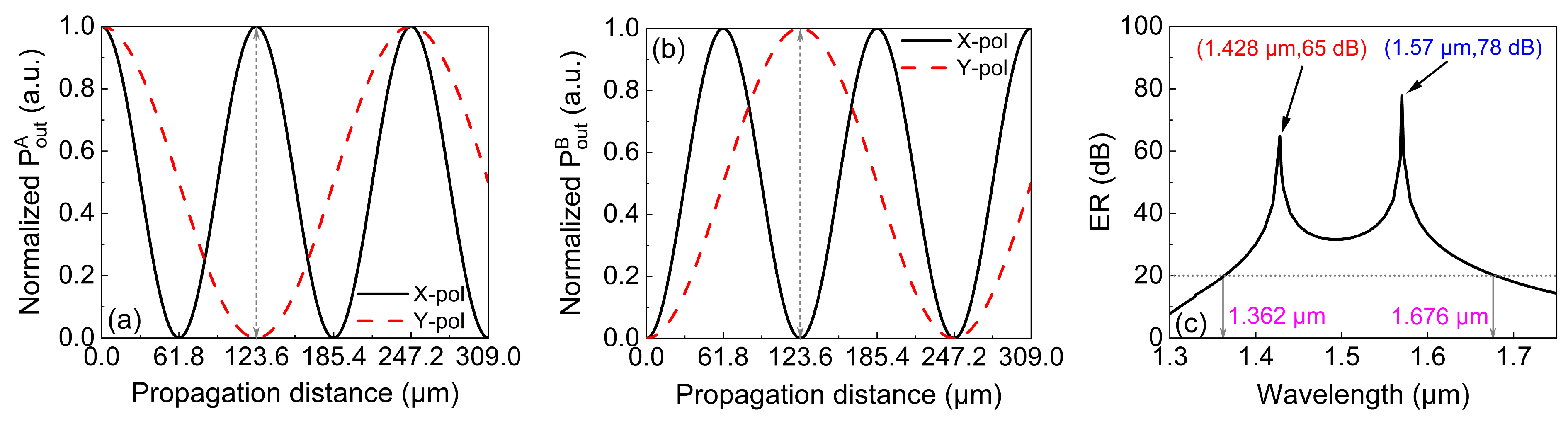
When the beam propagates in a dual-core PCF, its energy will periodically transfer from core A to core B. We define that when R = 2 or 1/2, the incident beam is completely separated into two polarizations. Assuming that the beam is initially injected into core A, the output power of the beam in the X-pol or Y-pol directions in core A can be calculated by [27,28]
P out i = P in cos 2 ß L p 2 CLi , i = X , Y ,
where P in represents the input power injected into core A. When P in is assumed to be 1, the output power P out is a parameter that is normalized for easy understanding. L p is the propagation distance. The extinction ratio (ER) is used to evaluate the beam-splitting performance of the PBS. The ER of the output powers between the X-pol and Y-pol beams in core A can be defined as [29,30]
E R = 10 log 10 P out X P out Y .

3. Influences of Structural Parameters on PBSes

To test whether the SPR effect can be stimulated in the designed DCPCF, we arbitrarily set the structural parameters as d = 1.1, d 1 = 1.3, d 2 = 1.0, and Λ = 2.0 μ m, while the thickness of the gold film was assumed to be t = 50 nm. A numerical software, COMSOL, was employed to simulate the SPR in the designed DCPCF. 
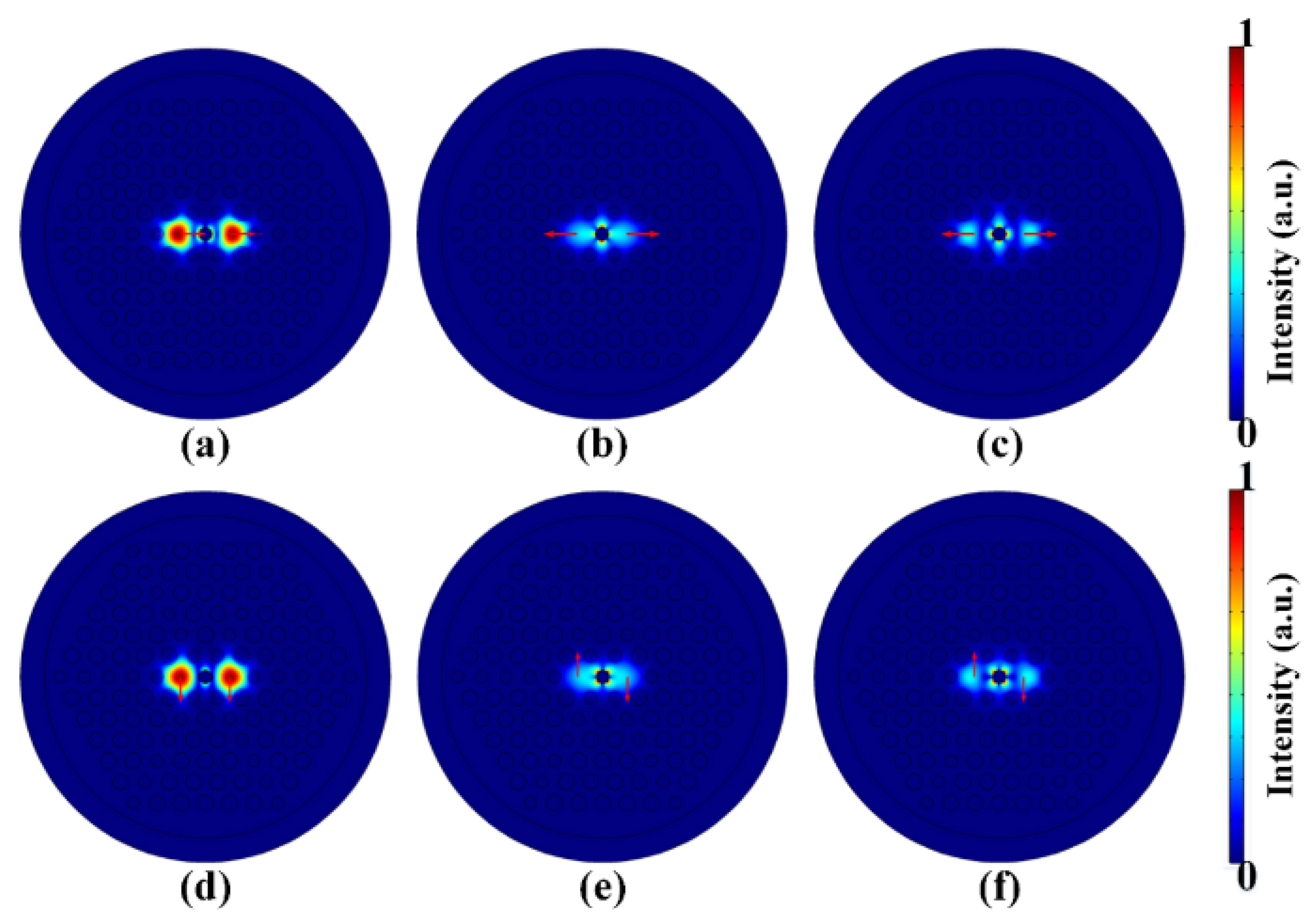
Figure 2 displays the mode fields of the X-pol and Y-pol directions, respectively. Specifically, Figure 2a–c show the X-pol even mode, X-pol odd mode, and X-pol second SPR mode, respectively, when the pump wavelength was 1.239 μ m. Similarly, Figure 2d–f show the Y-pol even mode, odd mode, and second SPR mode, respectively, when the pump central wavelength was 1.186 μ m. As can be seen, the intensity of the even mode was much stronger than that of the odd mode and second SPR mode. More importantly, the energies of both the X-pol and Y-pol even modes were tightly confined in cores A and B, indicating that the beam splitting mostly occurred in the even mode. Figure 2 confirms that the SPR mode can be effectively excited in the designed DCPCF, but with low intensity. Nevertheless, this weak SPR effect can still modify n eff .
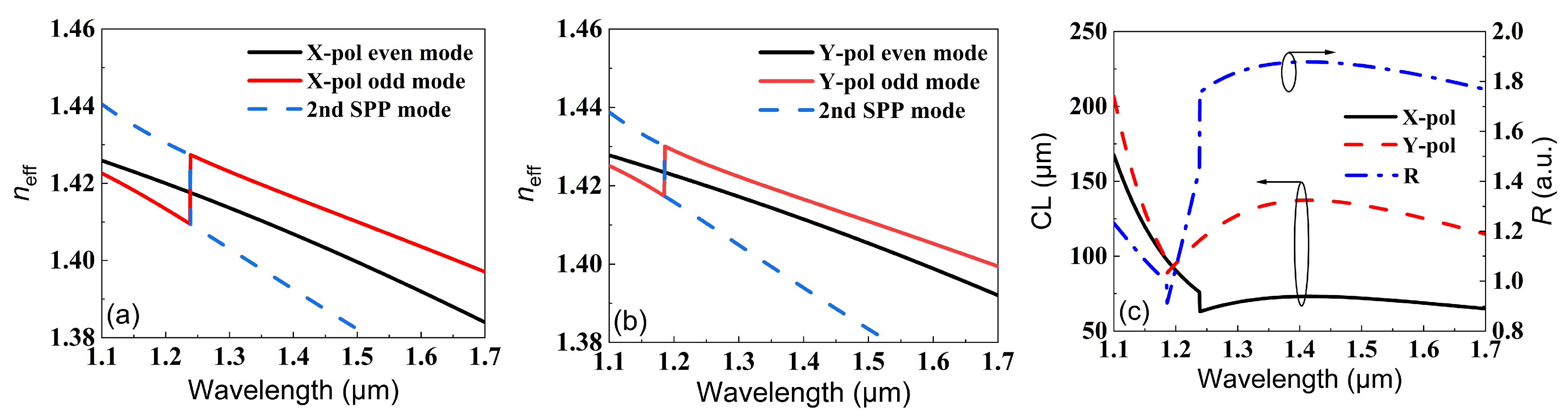
In order to show the influence of SPR on n eff for both the X-pol and Y-pol beams, the variations in n eff with wavelength for the two polarized beams are shown in Figure 3a,b. It should be noted that n eff values of the X-pol odd mode and second SPR mode were exchanged when the wavelength was 1.239 μ m, as shown in Figure 3a. Similarly, the n eff values of the Y-pol odd mode and second SPR mode were exchanged when the wavelength was 1.186 μ m, as shown in Figure 3b. This kind of sudden exchange resulted from the strong couplings between the odd mode and the second SPR mode. This coupling is unfavorable for polarization splitting, as the spatial profiles will be different after beam coupling. However, considering the low intensity of the odd and second SPR modes, the performance of the PBS will not be affected. The CLX, CLY, and R were also calculated for different wavelengths by using Equations (3) and (4), as shown in Figure 3c. The inflection point for every polarized beam corresponded to the mutations in Figure 3a,b. While the X-pol and Y-pol beams had inflection points at different wavelengths (1.18 μ m and 1.25 μ m, respectively), the resulting R approached 2 only after 1.3 μ m. More importantly, the CL for the Y-pol beam was larger than 125 μ m, which can be further optimized. In the following, the influences of the structural parameters of the DCPCF are optimized for R 2 under smaller CLs.
First, we considered the influence of the diameter of the central air hole, d. Figure 4a,b display the variations in CLX and CLY when d was increased from 0.9 to 1.3 μ m. It can be seen that for all d, the CLX decreased with the wavelength before the inflection point and then remained almost unchanged after the inflection point. More importantly, the wavelength position of the inflection point was red-shifted when d was increased, indicating the reduction of the operation bandwidth. However, the reduced bandwidth was compensated by smaller CLX, which is beneficial when designing short PBSes. The CLY in Figure 4b showed a similar trend to that of CLX, with the small difference that the CLY was almost unchanged with both the wavelength and d between 1.6 and 1.7 μ m. The corresponding R values were calculated according to Equation (4) and are shown in Figure 4c. Obviously, for the sake of larger values of R, increasing d was a good choice. The physical mechanism behind it is that changing the size of the central air hole essentially reshapes the distribution of the mode field. As a result, the mode couplings between the X-pol (Y-pol) odd mode and the X-pol (Y-pol) second SPR mode also vary. It should be noted that when d exceeds 1.2 μ m, R > 2 , and the operation bandwidth is decreased. Therefore, d should be chosen carefully to balance the value and operation bandwidth of R.
We then investigated the influence of d 1 by keeping the other four parameters unchanged. Figure 5 depicts the variations in the CLX, CLY, and R with the wavelength when d 1 was increased from 1.1 to 1.5 μ m. It can be seen from Figure 5a that the CLX remained unchanged with d 1 before the inflection points. After the inflection point, the CLX showed a tiny variation with the wavelength for a certain d 1 . The minimum CLX under d 1 = 1.5 μ m was 60 μ m, which was similar to that in Figure 4a. In addition, the minimum CLY in Figure 5b was almost the same as that in Figure 4b. Consequently, the maximum R in Figure 5c was equal to 1.88, which was smaller than that in Figure 4c. However, the smaller value of R covered a much broader wavelength range, i.e., 1.24–1.7 μ m. Therefore, d 1 has a small influence on the bandwidth and R compared with the influence of d.
Then, we studied the influence of d 2 on the CL and R. The relationship between the CLX and wavelength under different values of d 2 is shown in Figure 6a. It can be clearly seen that while similar variations in the CLX with wavelength could be observed, d 2 itself had almost no influence on the CLX. In contrast, the CLY in Figure 6b showed more changes with d 2 . However, compared with that in Figure 5b, the variation in CLY was a little bit smaller. As a result, the influence of d 2 on the CL was smaller than that of d 1 . However, it should be noted that the resulting R in Figure 6c showed a remarkable increment compared with that in Figure 5c when d 2 was increased. Actually, the maximum of R = 1.95 and the operation wavelength covered 1.25–1.7 μ m, which could be attributed to the completely invariant CLX when d 2 was increased. Compared with that in Figure 6c, the resulting R was quite close to the ideal value of 2.
While the optimization of d 2 was successful in obtaining a larger and broadband R, a short PBS is still required for a large σ . We further studied the influence of Λ on the CL and R. The simulation results are shown in Figure 7. Figure 7a,b depict the variations in CLX and CLY with the wavelength under different values of Λ . While both the CLX and CLY show similar trends of variation with the wavelength, the resulting minimum values of the CLX and CLY were only 40 and 65 μ m, which were smaller than those in Figure 6a and Figure 6b, respectively. In general, the CL rapidly increased with Λ . This was because larger values of Λ made the mode coupling more difficult. It is worth noting that the value of R in Figure 7c showed an opposite trend compared with that in Figure 6c, i.e., the value of R decreased with Λ . Furthermore, R was more influenced by Λ , but at the expense of a reduced operation bandwidth. Nevertheless, changing d 2 and Λ could result in the same bandwidth and value of R.
Finally, the influence of t on the CL and R were investigated. Figure 8 shows the variations in the CLX, CLY, and R with the wavelength under different values of t. In Figure 8a,b, the CLX and CLY remained the same over the whole wavelength range under different values of t. This means that t had almost no influence on the CL. As a result, t also had a negligible influence on R, especially in the wavelength range of 1.3–1.7 μ m. This is because small changes (5–20 nm) in t cannot influence the distribution of the optical mode. In Figure 8c, the largest values of R under different values of t showed tiny fluctuations around 1.9, which was smaller than the desired value of 2. Therefore, it is impossible to achieve R = 2 by only adjusting t.
From above simulation results, we can see that only d, d 2 , and Λ showed a significant relationship with the CL and R. Actually, d not only affected R, but also determined the wavelength position of the inflection point, namely, the operation bandwidth. In addition, Λ affected not only the value of R, but also the CL. In contrast, d 2 mainly affected the value of R and showed a slight influence on the resonance wavelength. In addition, the flatness of the R curve after the inflection point was also crucial because it determined the bandwidth of the PBS. In the five structural parameters, only d 1 enabled a flat R after the inflection point. Therefore, the optimization procedure can be summarized in the following three steps: first, adjusting d and d 2 to cause R to approach the ideal value of 2; second, changing the value of Λ for small CLs; third, controlling d 1 to improve the flatness of R after the inflection point. Following the above procedure, we obtained a set of optimized structural parameters of the DCPCF: d = 1.2 μ m, d 1 = 1.3 μ m, d 2 = 1.0 μ m, Λ = 2.0 μ m, and t = 50 nm.

4. Performance Analysis of the Optimized PBS

The CLX, CLY, and R calculated for the optimized PBS are shown in Figure 9 in the wavelength range of 1.0–1.8 μ m. It can be seen from Figure 9a that both the CLX and CLY were well below 130 μ m after the inflection point. More importantly, R slightly fluctuated around the ideal value of 2 after 1.35 μ m. Figure 9b depicts the details of R. It is shown that R varied between 1.98 and 2.02 in the wavelength range of 1.39 and 1.6 μ m. The maximum and minimum values of R were 2.015 and 1.985, which were very close to the ideal value of 2. When the pump wavelength was 1.405 or 1.568 μ m, R = 2 . For the latter wavelength, the corresponding CLX and CLY were 123.6 and 61.8 μ m, respectively. Therefore, 123.6 μ m could be selected as the length of the proposed PBS.
By using Equations (5) and (6), Figure 10a could be obtained, presenting the relationship between the normalized output power of the X-pol and Y-pol beams along the propagation when the initial beam was injected into core A. It is shown that when the propagation distance was 123.6 μ m, the normalized output power in the X-pol beam was 1, while that in the Y-pol beam was 0. At this moment, the X-pol and Y-pol beams were successfully separated into core A and core B, respectively. Figure 10b shows the relationship between the ER and the wavelength. Generally speaking, an ER larger than 20 dB can be considered an indication of successful splitting [31]. The bandwidth of a PBS is defined as the wavelength range in which the ER is larger than 20 dB. It can be seen from Figure 10b that the operation bandwidth was 314 nm and maximum ER was 78 dB at 1.57 μ m. We then calculated the value of σ of our work and compared it with the values reported in other work. It can be seen from Table 2 that the value of σ in this work was the largest among all works, which strongly suggests that our PBS is better than others in terms of length and operation bandwidth.

5. Conclusions

In summary, we designed a compact and broadband PBS based on the SPR effect by using a DCPCF that we designed. By studying the influences of the transversal structural parameters, we found that, except for the thickness of the gold film, other parameters played important roles in the PBS’s performance. Based on these findings, we summarized an efficient optimization procedure for quickly designing short and broadband PBSes. A set of optimized structural parameters was obtained by using this optimization procedure. The resulting PBS showed a length of 123.6 μ m, an operation bandwidth of 314 nm, and a maximum ER of 78 dB. Compared with other reported work, our PBS reached the best performance concerning the length and operation bandwidth. As the operation bandwidth is located in the telecommunication band, we believe that the proposed compact and broadband PBS has potential applications in miniaturized optical systems for sensing or communication.

Author Contributions

C.M. proposed the original idea, conducted the data analysis, and wrote most of the manuscript. Y.W. designed the structure of the PCF, employed the numerical software to conduct a detailed analysis of the PCF sensors, and plotted most of the figures. J.Y. helped check the final results and conclusions obtained from the numerical simulation, revised the manuscript, and supported the funding of this work. S.Q. made a careful check of the resulting figures and revised the manuscript. X.Z. revised the manuscript and provided plenty of fair suggestions. All authors have read and agreed to the published version of the manuscript.

Funding

This work was supported by the National Key Research and Development Project of China (Grant No. 2019YFB2204001), Fundamental Research Funds for the Central Universities (Grant No. 06500228), and Guangdong Basic and Applied Basic Research Foundation (Grant No. 2021A1515110507).

Institutional Review Board Statement

Not applicable.

Informed Consent Statement

Not applicable.

Data Availability Statement

Data are available upon request from the corresponding author.

Conflicts of Interest

The authors declare no conflict of interest.

References

  1. Broeng, J.; Mogilevstev, D.; Barkou, S.E. Photonic Crystal Fibers: A New Class of Optical Waveguides. Opt. Fiber Technol. 1999, 5, 305–330. [Google Scholar] [CrossRef]
  2. Russell, P. Photonic Crystal Fibers. Science 2003, 299, 358–362. [Google Scholar] [CrossRef] [PubMed]
  3. Lu, S.; Li, W.; Guo, H.; Lu, M. Analysis of birefringent and dispersive properties of photonic crystal fibers. Appl. Opt. 2011, 50, 5798–5802. [Google Scholar] [CrossRef]
  4. Hansen, K.P. Dispersion flattened hybrid-core nonlinear photonic crystal fiber. Opt. Express 2003, 11, 1503–1509. [Google Scholar] [CrossRef]
  5. Birks, T.A.; Knight, J.C.; Russell, P. Endlessly single-mode photonic crystal fiber. Opt. Lett. 1997, 22, 961–963. [Google Scholar] [CrossRef]
  6. Zhao, Y.; Li, S.; Wang, X.; Wang, G.; Shi, M.; Wu, J. Design of a novel multi-channel photonic crystal fiber polarization beam splitter. Opt. Commun. 2017, 400, 79–83. [Google Scholar] [CrossRef]
  7. He, F.T.; Shi, W.J.; Hui, Z.Q.; Zhan, F.; Zhang, Y.K. A dual-core PCF polarization splitter with five elliptical air holes based on tellurite glass. Opt. Quan. Electron. 2017, 49, 363. [Google Scholar] [CrossRef]
  8. Lou, J.; Cheng, T.; Li, S. High sensitivity photonic crystal fiber sensor based on dual-core coupling with circular lattice. Opt. Fiber Technol. 2019, 48, 110–116. [Google Scholar] [CrossRef]
  9. Liu, Q.; Xing, L.; Wu, Z. The highly sensitive magnetic field sensor based on photonic crystal fiber filled with nano-magnetic fluid. Opt. Commun. 2019, 452, 238–246. [Google Scholar] [CrossRef]
  10. Chaudhary, V.S.; Kumar, D.; Mishra, R.; Sharma, S. Hybrid Dual Core Photonic Crystal Fiber as Hydrostatic Pressure Sensor. Optik 2020, 210, 164497. [Google Scholar] [CrossRef]
  11. Chremmos, I.D.; Kakarantzas, G.; Uzunoglu, N.K. Modeling of a highly nonlinear chalcogenide dual-core photonic crystal fiber coupler. Opt. Commun. 2005, 251, 339–345. [Google Scholar] [CrossRef]
  12. He, F.T.; Shi, W.J.; Zhang, J.L.; Hui, Z.Q.; Zhan, F. Polarization splitter based on dual-core photonic crystal fiber with tellurite glass. Optik 2018, 164, 624–631. [Google Scholar] [CrossRef]
  13. Bai, Y.; Hao, R.; Yuan, B.; Cao, B. An ultrashort length and high extinction ratio polarization beam splitter based on dual-core PCF. J. Opt. 2021, 50, 257–263. [Google Scholar] [CrossRef]
  14. Jiang, L.; Zheng, Y.; Hou, L.; Zheng, K.; Peng, J.; Zhao, X. An ultrabraoadband polarization splitter based on square-lattice dual-core photonic crystal fiber with a gold wire. Opt. Commun. 2015, 351, 50–56. [Google Scholar] [CrossRef]
  15. Zi, J.; Li, S.; An, G.; Fan, Z. Short-length polarization splitter based on dual-core photonic crystal fiber with hexagonal lattice. Opt. Commun. 2016, 363, 80–84. [Google Scholar] [CrossRef]
  16. Wang, H.; Yan, X.; Li, S.; Zhang, X. Tunable surface plasmon resonance polarization beam splitter based on dual-core photonic crystal fiber with magnetic fluid. Opt. Quan. Electron. 2017, 49, 368. [Google Scholar] [CrossRef]
  17. Xu, Q.; Zhao, Y.; Xia, H.; Lin, S.B.; Zhang, Y. Ultrashort polarization splitter based on dual-core photonic crystal fibers with gold wire. Opt. Engin. 2018, 57, 046104. [Google Scholar] [CrossRef]
  18. Wang, J.; Pei, L.; Weng, S.; Wu, L.; Li, J.; Ning, T. Ultrashort polarization beam splitter based on liquid-filled dual-core photonic crystal fiber. Appl. Opt. 2018, 57, 3847–3852. [Google Scholar] [CrossRef] [PubMed]
  19. Lou, J.; Cheng, T.; Li, S. Ultra-short polarization beam splitter with square lattice and gold film based on dual-core photonic crystal fiber. Optik 2018, 179, 128–134. [Google Scholar] [CrossRef]
  20. Wang, G.; Lu, Y.; Yang, X.; Duan, L.; Yao, J. High-sensitivity magnetic field sensor based on a dual-core photonic crystal fiber. Appl. Opt. 2019, 58, 5800–5806. [Google Scholar] [CrossRef]
  21. Zhang, W.; Chen, H.; Liu, Y.; Ma, M.; Li, S. Analysis of a magnetic field sensor based on photonic crystal fiber selectively infiltrated with magnetic fluids. Opt. Fiber Technol. 2018, 46, 43–47. [Google Scholar] [CrossRef]
  22. Wang, J.; Liu, C.; Wang, F.; Su, W.; Yang, L.; Lv, J.; Fu, G.; Li, X.; Liu, Q.; Sun, T.; et al. Surface plasmon resonance sensor based on coupling effects of dual photonic crystal fibers for low refractive indexes detection. Res. Phys. 2020, 18, 103240. [Google Scholar] [CrossRef]
  23. Wang, X.; Li, S.; Liu, Q.; Wang, G.; Zhao, Y. Design of a Single-Polarization Single-Mode Photonic Crystal Fiber Filter Based on Surface Plasmon Resonance. Plasmonics 2017, 12, 1325–1330. [Google Scholar] [CrossRef]
  24. Zhao, T.; Jia, H.; Lian, Z.; Benson, T.; Lou, S. Ultra-broadband dual hollow-core anti-resonant fiber polarization splitter. Opt. Fiber Technol. 2019, 53, 102005. [Google Scholar] [CrossRef]
  25. Ponnusamy, M.; Prakash, J.; Vidyasagar, S.; Boopathi, C.S.; Amiri, I.S. Design of Polarization Splitter using Elliptically Dual Core – Cladding Photonic Crystal Fiber. Res. Phys. 2019, 3, 102279. [Google Scholar]
  26. Hagras, E.; Hameed, M.; Heikal, A.M.; Obayya, S.S.A. Multi-functional photonic crystal fiber splitter for the two communication bands. Opt. Fiber Technol. 2019, 52, 101986. [Google Scholar] [CrossRef]
  27. Sha, X.; Li, W.; Li, H.; Li, Z. Polarization splitter based on hybrid-cladding dual-core photonic crystal fibers. Optik 2015, 126, 2331–2334. [Google Scholar] [CrossRef]
  28. An, S.; Lv, J.; Yi, Z.; Liu, C.; Yang, L.; Wang, F.; Liu, Q.; Su, W.; Li, X.; Sun, T.; et al. Ultra-short and dual-core photonic crystal fiber polarization splitter composed of metal and gallium arsenide. Optik 2020, 226, 165779. [Google Scholar] [CrossRef]
  29. Zhang, Y.; Liu, H.; Chen, C.; Bai, B.; Tang, S. Temperature-controlled and multi-functional splitter based on dual-core photonic crystal fiber. Res. Phys. 2020, 19, 103578. [Google Scholar] [CrossRef]
  30. Shen, R.; Cheng, T.; Li, S.; Yan, X. Broadband Polarization Filter Based on Tellurite Photonic Crystal Fiber with High Extinction Ratio. Optik 2021, 245, 167721. [Google Scholar] [CrossRef]
  31. Zhao, X.T.; Hua, L.; Xiong, Q.; Jiang, G.H.; Cheng, J.R. Ultra-short and broadband polarization splitter based on PCF and metal surface plasmons resonance. Opt. Quan. Electron. 2019, 51, 162. [Google Scholar] [CrossRef]
Figure 1. A sectional view of the proposed DCPCF with its structual parameters, d , d 1 , d 2 , Λ , and t.
Micromachines 13 01663 g001
Figure 2. The mode fields of (a) the X-pol even mode, (b) X-pol odd mode, and (c) X-pol second SPR mode at the wavelength of 1.239 μ m. The mode-field distribution of (d) the Y-pol even mode, (e) Y-pol odd mode, and (f) Y-pol second SPR mode at the wavelength of 1.186 μ m.
Micromachines 13 01663 g002
Figure 3. The effective refractive indexes of (a) the X-pol and (b) Y-pol modes. (c) The variations in CLX, CLY, and R with wavelength.
Micromachines 13 01663 g003
Figure 4. The variations in (a) the CLX and (b) CLY with the wavelength under different values of d. (c) The variations in R with the wavelength under different values of d.
Micromachines 13 01663 g004
Figure 5. The variations in (a) the CLX and (b) CLY with the wavelength under different values of d 1 . (c) The variations in R with the wavelength under different values of d 1 .
Micromachines 13 01663 g005
Figure 6. The variations in (a) the CLX and (b) CLY with the wavelength under different values of d 2 . (c) The variations in R with the wavelength under different values of d 2 .
Micromachines 13 01663 g006
Figure 7. The variations in (a) the CLX and (b) CLY with the wavelength under different values of Λ . (c) The variations in R with the wavelength under different values of Λ .
Micromachines 13 01663 g007
Figure 8. The variations in (a) the CLX and (b) CLY with the wavelength under different values of t. (c) The variations in R with the wavelength under different values of t.
Micromachines 13 01663 g008
Figure 9. (a) The variations in CLX, CLY, and R with the wavelength for the optimized DCPCF. (b) Zooming in on R in the wavelength range of 1.39–1.6 μ m.
Micromachines 13 01663 g009
Figure 10. The relationship between the normalized output power and propagation distance in (a) core A and (b) in core B, and (c) the ER in core A between 1.3 and 1.75 μ m with the optimized structural parameters.
Micromachines 13 01663 g010
Table 1. Parameters for the Sellmeier equation of silica.
Subscript 1Subscript 2Subscript 3
A0.69616630.40794260.8974794
B0.0684043 μ m0.1162414 μ m9.896161 μ m
Table 2. Comparison of the PBS performance between this work and other reported work.
Refs.PBS StructureLength ( μ m)Bandwidth (nm)Ratio σ
[14]square PCF with gold wire4036430 1 × 10 4
[15]hexagonal PCF without gold24917 6.8 × 10 5
[16]magnetic-fluid-core PCF with gold film5112189 3.7 × 10 5
[17]PCF with elliptical holes and gold film29019.2 6.6 × 10 5
[18]PCF filled with liquid without gold7844 5.6 × 10 4
[19]octagonal PCF with gold film47.26104 2.2 × 10 3
This workhexagonal PCF with gold film123.6314 2.5 × 10 3
Publisher’s Note: MDPI stays neutral with regard to jurisdictional claims in published maps and institutional affiliations.

