
Electric Field-Driven Liquid Metal Droplet Generation and Direction Manipulation


Abstract
:1. Introduction
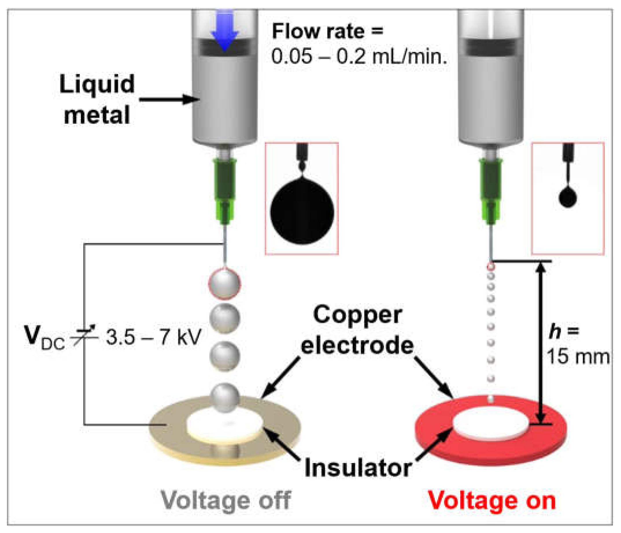
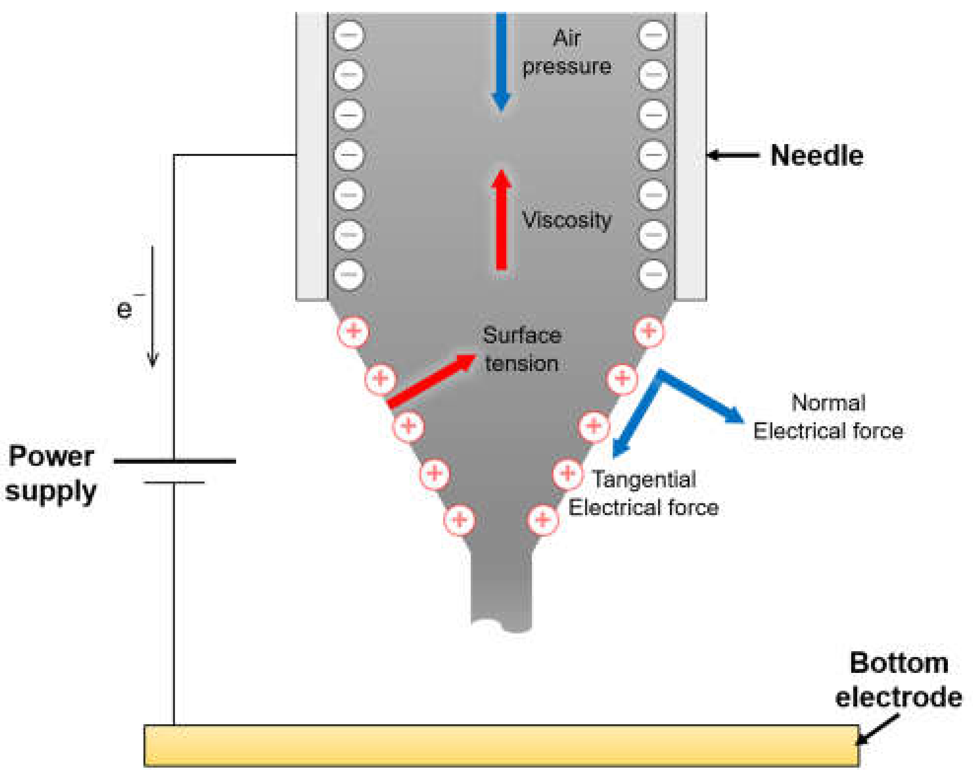
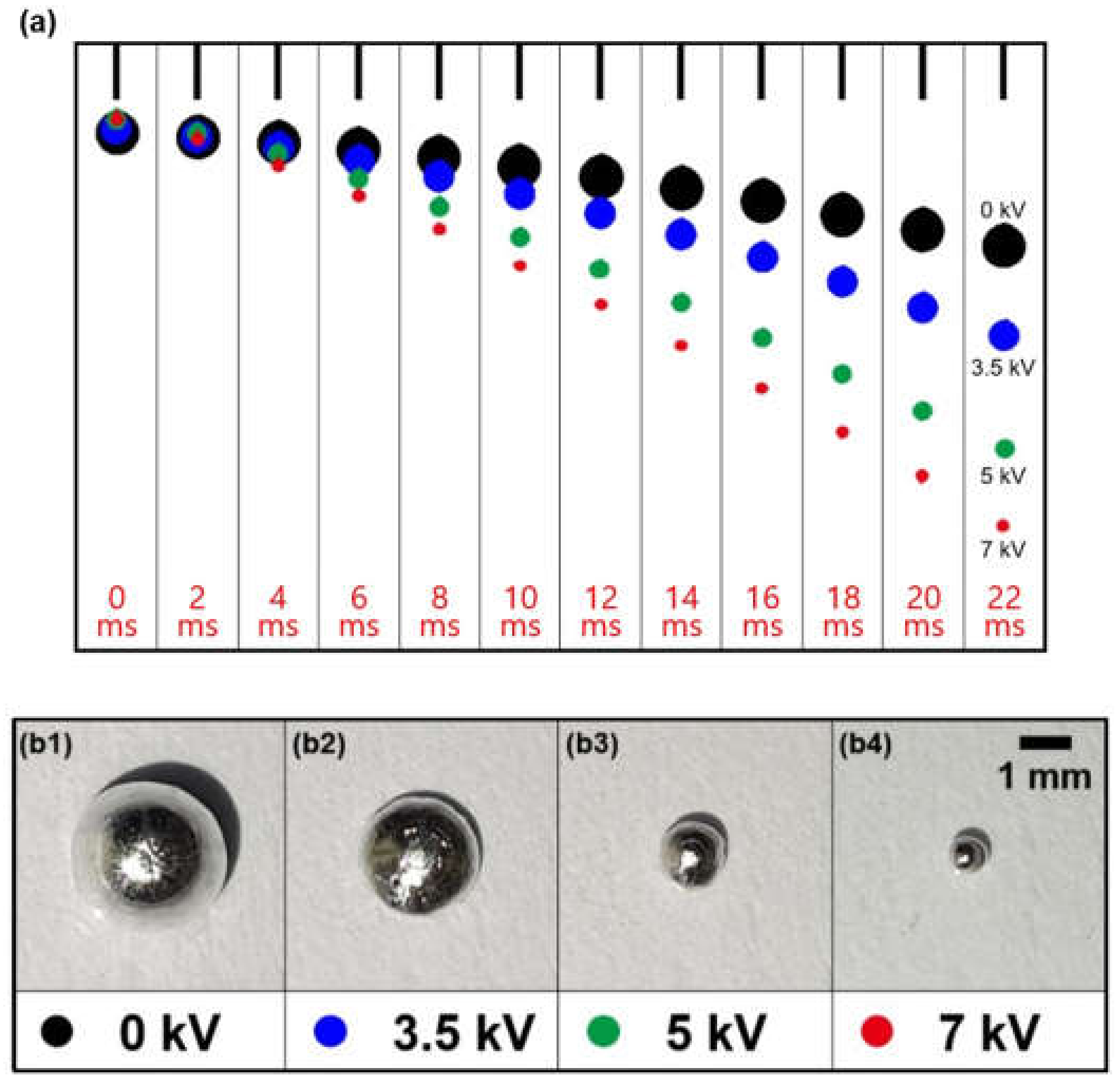
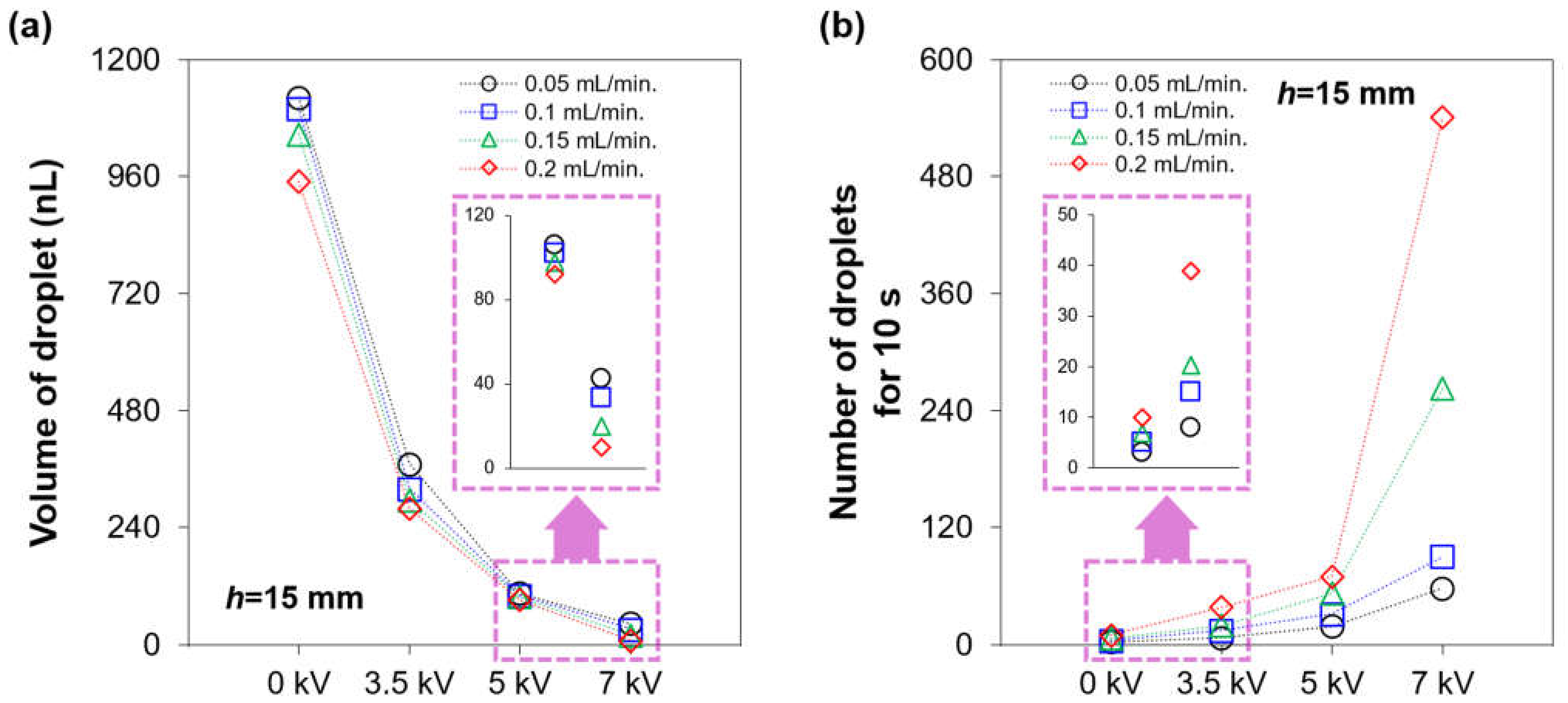
2. Electric Field-Driven Liquid Metal Droplet Generation
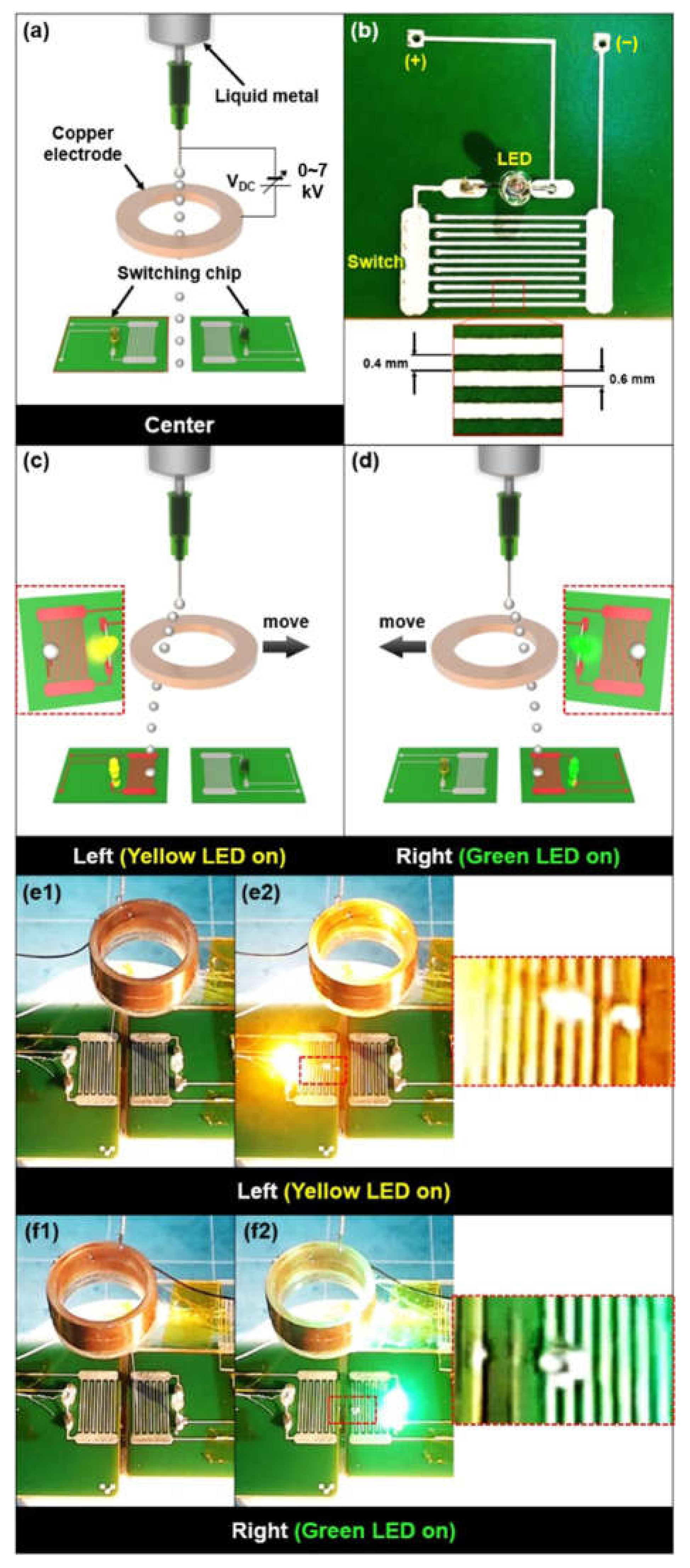
3. Electric Field-Driven Direction Manipulation
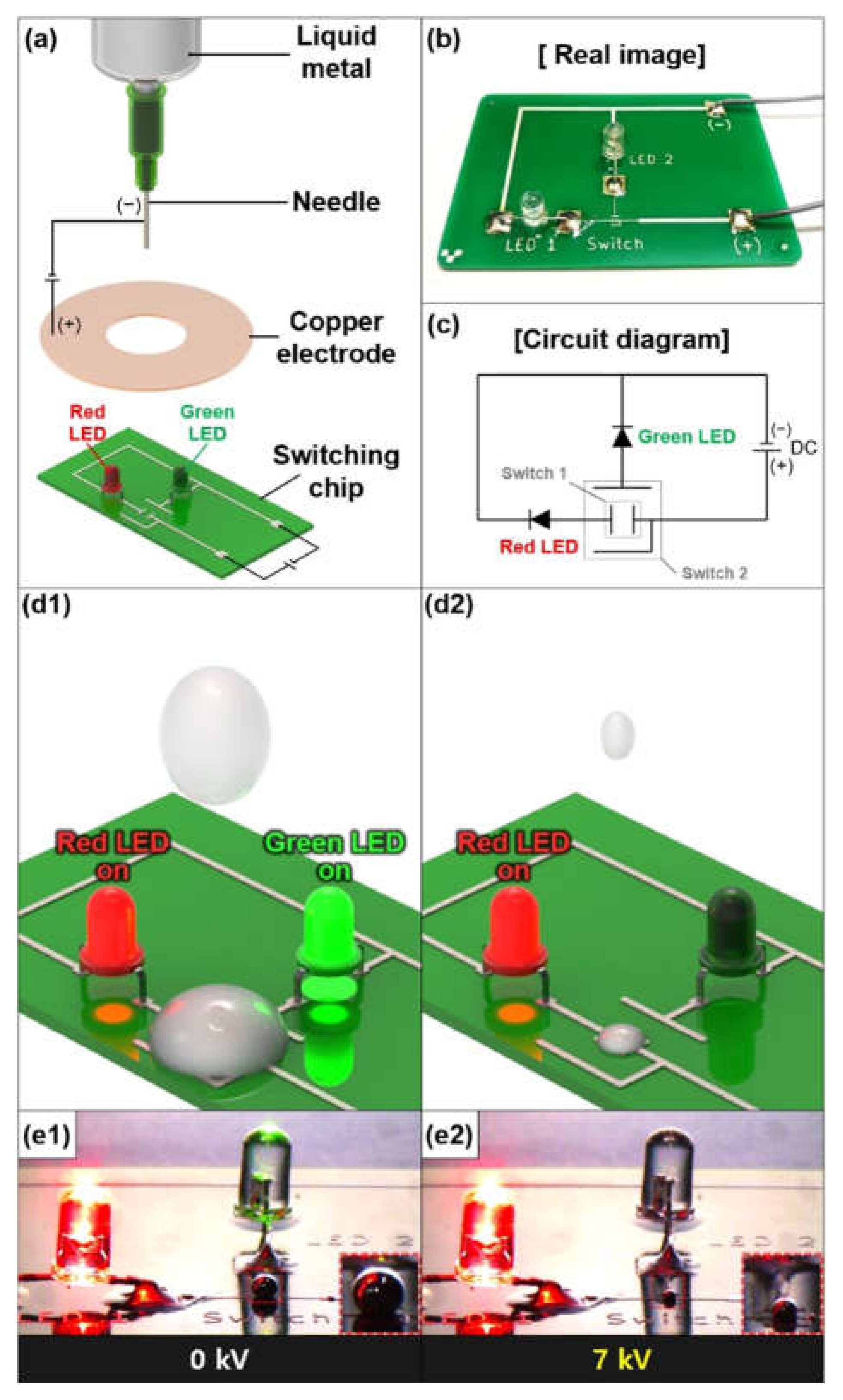
4. Controlled Short Circuit Demonstration
5. Conclusions
Supplementary Materials
Author Contributions
Funding
Data Availability Statement
Conflicts of Interest
References
- Jeong, J.; Chung, S.K.; Lee, J.B.; Kim, D. Electro-Hydrodynamic Droplet Generation, Manipulation, and Repulsion of Oxidized Gallium-Based Liquid Metal. In Proceedings of the 2019 20th International Conference on Solid-State Sensors, Actuators and Microsystems & Eurosensors XXXIII (TRANSDUCERS & EUROSENSORS XXXIII), Berlin, Germany, 23–27 June 2019; pp. 2337–2339. [Google Scholar]
- Fylladitakis, E.D.; Theodoridis, M.P.; Moronis, A.X. Review on the history, research, and applications of electrohydrodynamics. IEEE Trans. Plasma Sci. 2014, 42, 358–375. [Google Scholar] [CrossRef]
- Kim, B.H.; Onses, M.S.; Lim, J.B.; Nam, S.; Oh, N.; Kim, H.; Yu, K.J.; Lee, J.W.; Kim, J.H.; Kang, S.K.; et al. High-resolution patterns of quantum dots formed by electrohydrodynamic jet printing for light-emitting diodes. Nano Lett. 2015, 15, 969–973. [Google Scholar] [CrossRef] [PubMed] [Green Version]
- He, J.; Xu, F.; Cao, Y.; Liu, Y.; Li, D.; Jin, Z. Electrohydrodynamic direct-writing lithography: An alternative maskless technique for microstructure fabrication. Appl. Phys. Lett. 2014, 105, 253109. [Google Scholar] [CrossRef]
- Tian, H.; Shao, J.; Ding, Y.; Li, X.; Li, X.; Liu, H. Influence of distorted electric field distribution on microstructure formation in the electrohydrodynamic patterning process. J. Vac. Sci. Technol. B 2011, 29, 041606. [Google Scholar] [CrossRef]
- Zhang, B.; He, J. Electrohydrodynamic printing of sub-microscale fibrous architectures with improved cell adhesion capacity. Virtual Phys. Prototyp. 2020, 15, 62–74. [Google Scholar] [CrossRef]
- Park, S.E.; Kim, S.; Lee, D.Y.; Kim, E.; Hwang, J. Fabrication of silver nanowire transparent electrodes using electrohydrodynamic spray deposition for flexible organic solar cells. J. Mater. Chem. A 2013, 1, 14286–14293. [Google Scholar] [CrossRef]
- Kwack, Y.J.; Choi, W.S. Solution-processed zinc-tin-oxide thin-film transistor by electrohydrodynamic spray. Electron. Mater. Lett. 2012, 8, 341–344. [Google Scholar] [CrossRef]
- Sofokleous, P.; Stride, E.; Bonfield, W.; Edirisinghe, M. Design, construction and performance of a portable handheld electrohydrodynamic multi-needle spray gun for biomedical applications. Mater. Sci. Eng. C 2013, 33, 213–223. [Google Scholar] [CrossRef]
- Cloupeau, M.; Prunet-Foch, B. Electrohydrodynamic spraying functioning modes: A critical review. J. Aerosol Sci. 1994, 25, 1021–1036. [Google Scholar] [CrossRef]
- Jaworek, A.; Krupa, A. Classification of the modes of EHD spraying. J. Aerosol Sci. 1999, 30, 873–893. [Google Scholar] [CrossRef]
- Owsenek, B.L.; Seyed-Yagoobi, J. Theoretical and experimental study of electrohydrodynamic heat transfer enhancement through wire-plate corona discharge. J. Heat Transfer. 1997, 119, 604–610. [Google Scholar] [CrossRef]
- Allen, P.H.G.; Karayiannis, T.G. Electrohydrodynamic enhancement of heat transfer and fluid flow. Heat Recover. Syst. CHP 1995, 15, 389–423. [Google Scholar] [CrossRef]
- Sheikholeslami, M.; Chamkha, A.J. Electrohydrodynamic free convection heat transfer of a nanofluid in a semi-annulus enclosure with a sinusoidal wall. Numer. Heat Transf. A Appl. 2016, 69, 781–793. [Google Scholar] [CrossRef]
- Robinson, M. Movement of air in the electric wind of the corona discharge. Trans. Am. Inst. Electr. Eng. 1961, 80, 143–150. [Google Scholar] [CrossRef]
- Stuetzer, O.M. Ion drag pumps. J. Appl. Phys. 1960, 31, 136–146. [Google Scholar] [CrossRef]
- Moon, J.D.; Hwang, D.H.; Geum, S.T. An EHD gas pump utilizing a ring/needle electrode. IEEE Trans. Dielectr. Electr. Insul. 2009, 16, 352–358. [Google Scholar] [CrossRef]
- Crowley, J.M.; Wright, G.S.; Chato, J.C. Selecting a working fluid to increase the efficiency and flow rate of an EHD pump. IEEE Trans. Ind. Appl. 1990, 26, 42–49. [Google Scholar] [CrossRef] [Green Version]
- Krueger, A.P.; Hicks, W.; Beckett, J.C. Effects of unipolar air ions on microorganisms and on evaporation. J. Frankl. Inst. 1958, 266, 9–19. [Google Scholar] [CrossRef]
- Chen, Y.H.; Barthakur, N.N. Potato slab dehydration by air ions from corona discharge. Int. J. Biometeorol. 1991, 35, 67–70. [Google Scholar] [CrossRef]
- Lai, F.C.; Lai, K.W. EHD-enhanced drying with wire electrode. Dry Technol. 2002, 20, 1393–1405. [Google Scholar] [CrossRef]
- Lai, F.C. A prototype of EHD-enhanced drying system. J. Electrostat. 2010, 68, 101–104. [Google Scholar] [CrossRef]
- Christenson, E.A.; Moller, P.S. Ion-neutral propulsion in atmospheric media. AIAA J. 1967, 5, 1768–1773. [Google Scholar] [CrossRef]
- Wilson, J.; Perkins, H.D.; Thompson, W.K. An Investigation of Ionic Wind Propulsion; NASA: Ohio, OH, USA, 2009; TM-2009-215822. [Google Scholar]
- Masuyama, K. Performance characterization of electrohydrodynamic propulsion devices. Master’s Thesis, Department Aeronautics Astronautics, Massachusetts Institute of Technology, Massachusetts, MA, USA, 2012. [Google Scholar]
- Park, J.U.; Hardy, M.; Kang, S.J.; Barton, K.; Adair, K.; Mukhopadhyay, D.K.; Lee, C.Y.; Strano, M.S.; Alleyne, A.G.; Georgiadis, J.G.; et al. High-resolution electrohydrodynamic jet printing. Nat. Mater. 2007, 6, 782–789. [Google Scholar] [CrossRef]
- Lee, D.Y.; Shin, Y.S.; Park, S.E.; Yu, Y.U.; Hwang, J. Electrohydrodynamic printing of silver nanoparticles by using a focused nanocolloid jet. Appl. Phys. Lett. 2007, 90, 081905. [Google Scholar] [CrossRef] [Green Version]
- Onses, M.S.; Sutanto, E.; Ferreira, P.M.; Alleyne, A.G.; Rogers, J.A. Mechanisms, capabilities, and applications of high-resolution electrohydrodynamic jet printing. Small 2015, 11, 4237–4266. [Google Scholar] [CrossRef]
- Wu, C.; Tetik, H.; Cheng, J.; Ding, W.; Guo, H.; Tao, X.; Zhou, N.; Zi, Y.; Wu, Z.; Lin, D.; et al. Electrohydrodynamic jet printing driven by a triboelectric nanogenerator. Adv. Funct. Mater. 2019, 29, 1901102. [Google Scholar] [CrossRef]
- Raje, P.V.; Murmu, N.C. A review on electrohydrodynamic-inkjet printing technology. Int. J. Emerg. Technol. Adv. Eng. 2014, 4, 174–183. [Google Scholar]
- Kim, D.S.; Khan, A.; Rahman, K.; Khan, S.; Kim, H.C.; Choi, K.H. Drop-on-demand direct printing of colloidal copper nanoparticles by electrohydrodynamic atomization. Mater. Manuf. Process. 2011, 26, 1196–1201. [Google Scholar] [CrossRef]
- Pan, Y.; Zeng, L. Simulation and validation of droplet generation process for revealing three design constraints in electrohydrodynamic jet printing. Micromachines 2019, 10, 94. [Google Scholar] [CrossRef] [Green Version]
- Lee, M.W.; Kim, N.Y.; Yoon, S.S. On pinchoff behavior of electrified droplets. J. Aerosol. Sci. 2013, 57, 114–124. [Google Scholar] [CrossRef]
- Back, S.Y.; Song, C.H.; Yu, S.; Lee, H.J.; Kim, B.S.; Yang, N.Y.; Jeong, S.H.; Ahn, H. Drop-on-demand printing of carbon black ink by electrohydrodynamic jet printing. J. Nanosci. Nanotechnol. 2012, 12, 446–450. [Google Scholar] [CrossRef]
- Mishra, S.; Barton, K.L.; Alleyne, A.G.; Ferreira, P.M.; Rogers, J.A. High-speed and drop-on-demand printing with a pulsed electrohydrodynamic jet. J. Micromech. Microeng. 2010, 20, 095026. [Google Scholar] [CrossRef] [Green Version]
- Vespini, V.; Coppola, S.; Todino, M.; Paturzo, M.; Bianco, V.; Grilli, S.; Ferraro, P. Forward electrohydrodynamic inkjet printing of optical microlenses on microfluidic devices. Lab Chip 2016, 16, 326–333. [Google Scholar] [CrossRef]
- Schneider, J.; Rohner, P.; Thureja, D.; Schmid, M.; Galliker, P.; Poulikakos, D. Electrohydrodynamic nanodrip printing of high aspect ratio metal grid transparent electrodes. Adv. Funct. Mater. 2016, 26, 833–840. [Google Scholar] [CrossRef]
- Jang, Y.; Kim, J.; Byun, D. Invisible metal-grid transparent electrode prepared by electrohydrodynamic (EHD) jet printing. J. Phys. D Appl. Phys. 2013, 46, 155103. [Google Scholar] [CrossRef]
- Han, Y.; Dong, J. Electrohydrodynamic (EHD) Printing of Molten Metal Ink for Flexible and Stretchable Conductor with Self-Healing Capability. Adv. Mater. Technol. 2018, 3, 1700268. [Google Scholar] [CrossRef]
- Jin, S.W.; Park, J.; Hong, S.Y.; Park, H.; Jeong, Y.R.; Park, J.; Lee, S.S.; Ha, J.S. Stretchable loudspeaker using liquid metal microchannel. Sci. Rep. 2015, 5, 11695. [Google Scholar] [CrossRef] [PubMed] [Green Version]
- Li, G.; Wu, X.; Lee, D.W. A galinstan-based inkjet printing system for highly stretchable electronics with self-healing capability. Lab Chip 2016, 16, 1366–1373. [Google Scholar] [CrossRef]
- Wang, Q.; Yu, Y.; Yang, J.; Liu, J. Fast fabrication of flexible functional circuits based on liquid metal dual-trans printing. Adv. Mater. 2015, 27, 7109–7116. [Google Scholar] [CrossRef]
- Yang, Y.; Sun, N.; Wen, Z.; Cheng, P.; Zheng, H.; Shao, H.; Xia, Y.; Chen, C.; Lan, H.; Xie, X.; et al. Liquid-metal-based super-stretchable and structure-designable triboelectric nanogenerator for wearable electronics. ACS Nano 2018, 12, 2027–2034. [Google Scholar] [CrossRef]
- Ma, K.Q.; Liu, J. Heat-driven liquid metal cooling device for the thermal management of a computer chip. J. Phys. D Appl. Phys. 2007, 40, 4722. [Google Scholar] [CrossRef]
- Miner, A.; Ghoshal, U. Cooling of high-power-density microdevices using liquid metal coolants. Appl. Phys. Lett. 2004, 85, 506–508. [Google Scholar] [CrossRef]
- Kim, D.; Pierce, R.G.; Henderson, R.M.; Doo, S.J.; Yoo, K.; Lee, J.-B. Liquid metal actuation-based reversible frequency tunable monopole antenna. Appl. Phys. Lett. 2014, 105, 234104. [Google Scholar] [CrossRef] [Green Version]
- Kim, D.; Pierce, P.G.; Henderson, R.; Doo, S.J.; Yoo, K.; Lee, J.B. On-demand frequency tunability of fluidic antenna implemented with gallium-based liquid metal alloy. Eur. Phys. J.-Appl. Phys. 2017, 78, 11101. [Google Scholar] [CrossRef]
- Khan, M.R.; Hayes, G.J.; So, J.H.; Lazzi, G.; Dickey, M.D. A frequency shifting liquid metal antenna with pressure responsiveness. Appl. Phys. Lett. 2011, 99, 013501. [Google Scholar] [CrossRef]
- Wang, J.; Liu, S.; Guruswamy, S.; Nahata, A. Reconfigurable liquid metal based terahertz metamaterials via selective erasure and refilling to the unit cell level. Appl. Phys. Lett. 2013, 103, 221116. [Google Scholar] [CrossRef]
- Kasirga, T.S.; Ertas, Y.N.; Bayindir, M. Microfluidics for reconfigurable electromagnetic metamaterials. Appl. Phys. Lett. 2009, 95, 214102. [Google Scholar] [CrossRef]
- Yu, Y.; Jhang, J.; Liu, J. Biomedical implementation of liquid metal ink as drawable ECG electrode and skin circuit. PLoS ONE 2013, 8, e587711. [Google Scholar] [CrossRef]
- Yi, L.; Liu, J. Liquid metal biomaterials: A newly emerging area to tackle modern biomedical challenges. Int. Mater. Rev. 2017, 62, 415–440. [Google Scholar] [CrossRef]
- Liu, T.; Sen, P.; Kim, C.J. Characterization of nontoxic liquid-metal alloy galinstan for applications in microdevices. J. Microelectromech. S. 2011, 21, 443–450. [Google Scholar] [CrossRef] [Green Version]
- Scharmann, F.; Cherkashinin, G.; Breternitz, V.; Knedlilk, C.; Hartung, G.; Weber, T.; Schaefer, J.A. Viscosity effect on GaInSn studied by XPS. Surf. Interface Anal. 2004, 36, 981–985. [Google Scholar] [CrossRef]
- Jeon, J.; Lee, J.B.; Chung, S.K.; Kim, D. On-demand magnetic manipulation of liquid metal in microfluidic channels for electrical switching applications. Lab Chip 2017, 17, 128–133. [Google Scholar] [CrossRef]
- Jeong, J.; Seo, J.; Lee, J.B.; Chung, S.K.; Kim, D. Electromagnet polarity dependent reversible dynamic behavior of magnetic liquid metal marble. Mater. Res. Express 2020, 7, 015708. [Google Scholar] [CrossRef]
- Jeong, J.; Lee, J.B.; Chung, S.K.; Kim, D. Electromagnetic three dimensional liquid metal manipulation. Lab Chip 2019, 19, 3261–3267. [Google Scholar] [CrossRef]
- Sun, Y.; Xu, S.; Tan, S.; Liu, J. Multiple electrohydrodynamic effects on the morphology and running behavior of tiny liquid metal motors. Micromachines 2018, 9, 192. [Google Scholar] [CrossRef] [Green Version]
- Fang, W.Q.; He, Z.Z.; Liu, J. Electro-hydrodynamic shooting phenomenon of liquid metal stream. Appl. Phys. Lett. 2014, 105, 134104. [Google Scholar] [CrossRef] [Green Version]
- Yudistira, H.T.; Nguyen, V.D.; Dutta, P.; Byun, D. Flight behavior of charged droplets in electrohydrodynamic inkjet printing. Appl. Phys. Lett. 2010, 96, 023503. [Google Scholar] [CrossRef] [Green Version]
- Xu, C.; Huang, Y.; Fu, J.; Markwald, R.R. Electric field-assisted droplet formation using piezoactuation-based drop-on-demand inkjet printing. J. Micromech. Microeng. 2014, 24, 115011. [Google Scholar] [CrossRef]
- Chen, C.-H.; Saville, D.A.; Aksay, I.A. Scaling laws for pulsed electrohydrodynamic drop formation. Appl. Phys. Lett. 2006, 89, 124103. [Google Scholar] [CrossRef] [Green Version]
- Choi, H.K.; Park, J.U.; Park, O.O.; Ferreira, P.M.; Georgiadis, J.G.; Rogers, J.A. Scaling laws for jet pulsations associated with high-resolution electrohydrodynamic printing. Appl. Phys. Lett. 2008, 92, 123109. [Google Scholar] [CrossRef] [Green Version]
- Zhang, G.; Qian, L.; Zhao, J.; Zhou, H.; Lan, H. High-Resolution Electric-Field-Driven Jet 3D Printing and Applications in 3D Printing; IntechOpen: London, UK, 2018; p. 23. [Google Scholar]
- Eyring, C.F.; Mackeown, S.S.; Millikan, R.A. Fields currents from points. Phys. Rev. 1928, 31, 900. [Google Scholar] [CrossRef]
- Marginean, I.; Nemes, P.; Vertes, A. Order-chaos-order transitions in electrosprays: The electrified dripping faucet. Phys. Rev. Lett. 2006, 97, 064502. [Google Scholar] [CrossRef] [PubMed] [Green Version]
- Kim, B.; Nam, H.; Kim, S.J.; Sung, J.; Joo, S.W. Control of charged droplets using electrohydrodynamic repulsion for circular droplet patterning. J. Micromech. Microeng. 2011, 21, 075020. [Google Scholar] [CrossRef]
- Fillmore, G.L.; Buehner, W.L.; West, D.L. Drop charging and deflection in an electrostatic ink jet printer. IBM J. Res. Dev. 1977, 21, 37–47. [Google Scholar] [CrossRef]


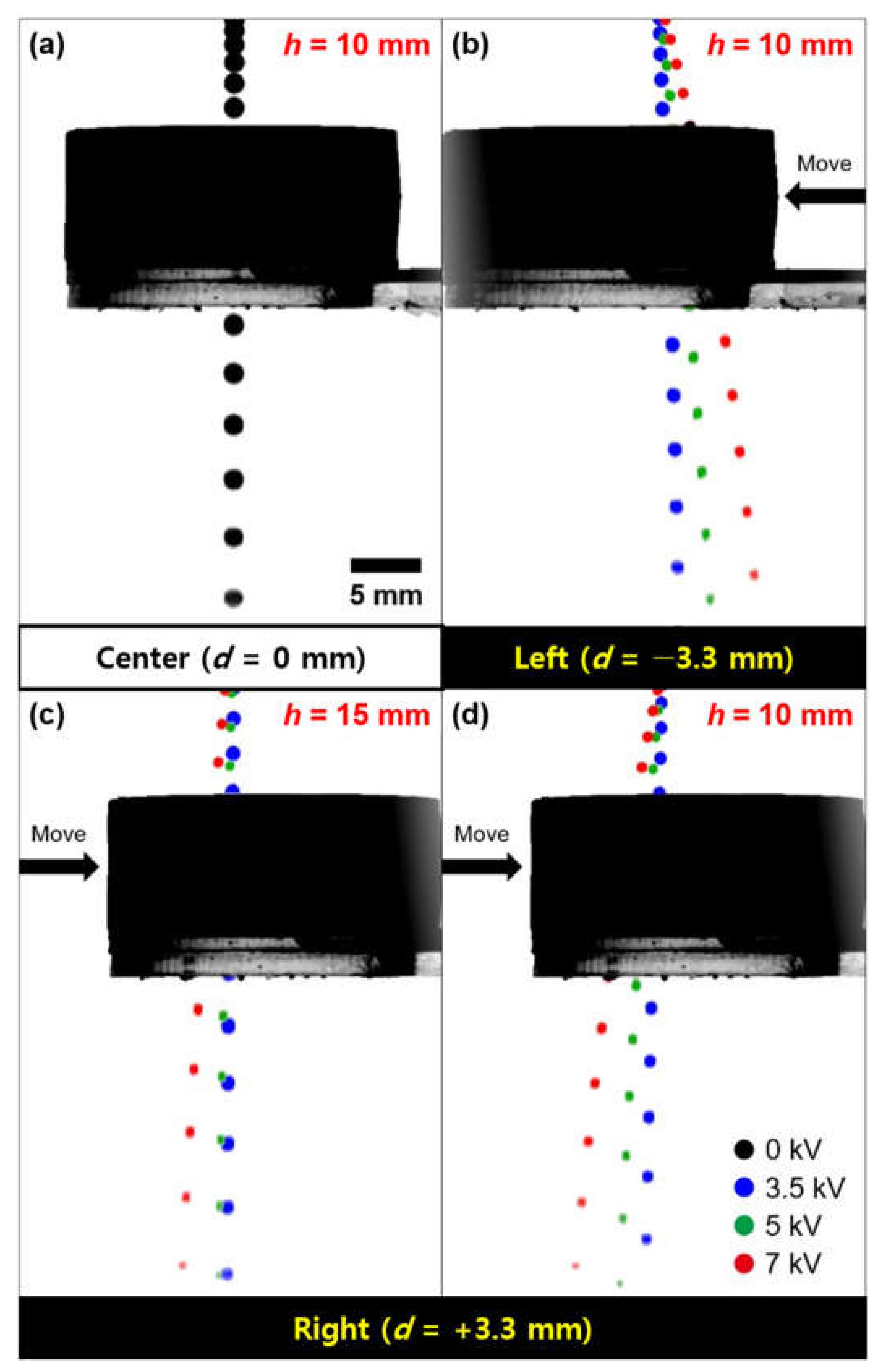
| Position | Angle of the Trace (°) | ||
|---|---|---|---|
| 3.5 kV | 5 kV | 7 kV | |
| Left (h = 10 mm) | 1.6 | 6.5 | 12.8 |
| Right (h = 10 mm) | 1.1 | 4.6 | 11.4 |
| Right (h = 15 mm) | 0.6 | 1.7 | 5.6 |
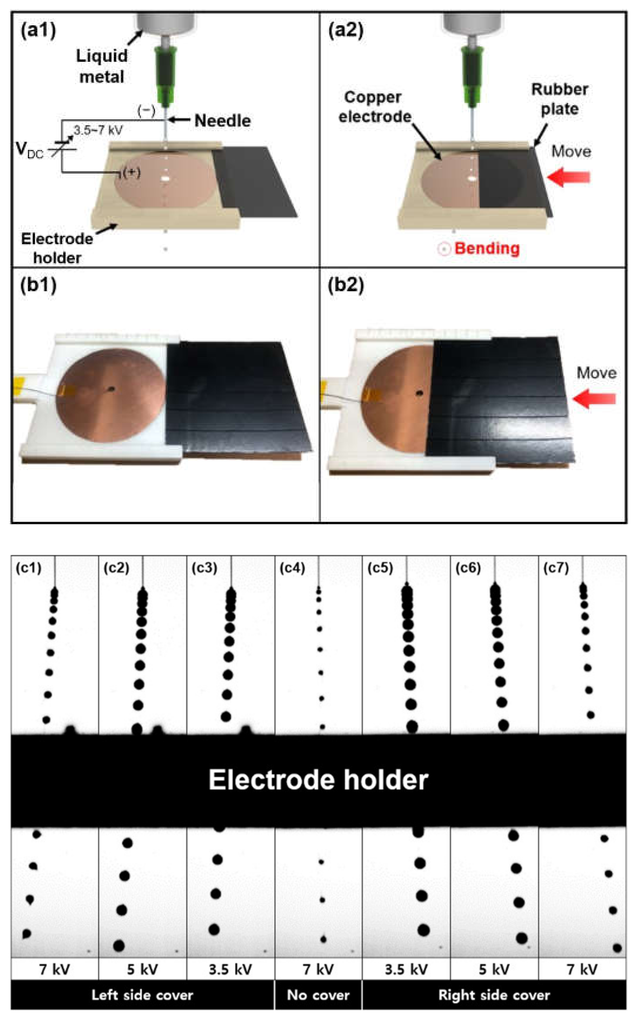
| Covered areas of Electrode | Angle of the Trace (°) | ||
|---|---|---|---|
| 3.5 kV | 5 kV | 7 kV | |
| Left | 2.7 | 3.9 | 5.1 |
| Right | 2.9 | 4 | 5.2 |
Publisher’s Note: MDPI stays neutral with regard to jurisdictional claims in published maps and institutional affiliations. |
© 2021 by the authors. Licensee MDPI, Basel, Switzerland. This article is an open access article distributed under the terms and conditions of the Creative Commons Attribution (CC BY) license (https://creativecommons.org/licenses/by/4.0/).
Share and Cite
Jeong, J.; Chung, S.; Lee, J.-B.; Kim, D. Electric Field-Driven Liquid Metal Droplet Generation and Direction Manipulation. Micromachines 2021, 12, 1131. https://doi.org/10.3390/mi12091131
Jeong J, Chung S, Lee J-B, Kim D. Electric Field-Driven Liquid Metal Droplet Generation and Direction Manipulation. Micromachines. 2021; 12(9):1131. https://doi.org/10.3390/mi12091131
Chicago/Turabian StyleJeong, Jinwon, Sangkug Chung, Jeong-Bong Lee, and Daeyoung Kim. 2021. "Electric Field-Driven Liquid Metal Droplet Generation and Direction Manipulation" Micromachines 12, no. 9: 1131. https://doi.org/10.3390/mi12091131