
A Compact Linear Ultrasonic Motor Composed by Double Flexural Vibrator


Abstract
:1. Introduction
2. Working Principle
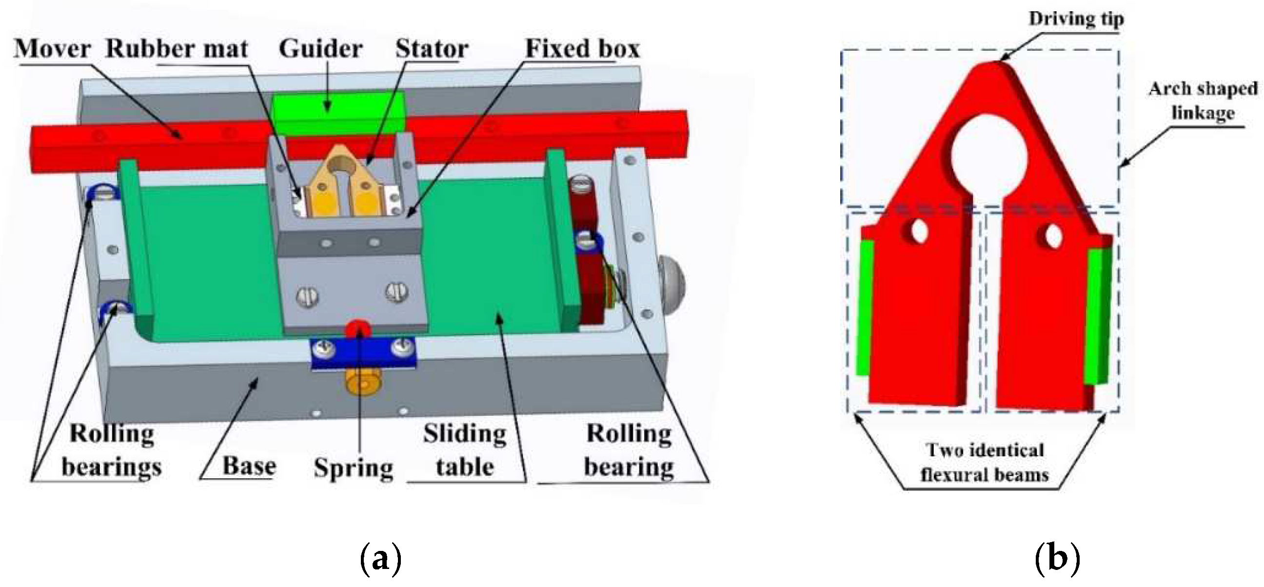
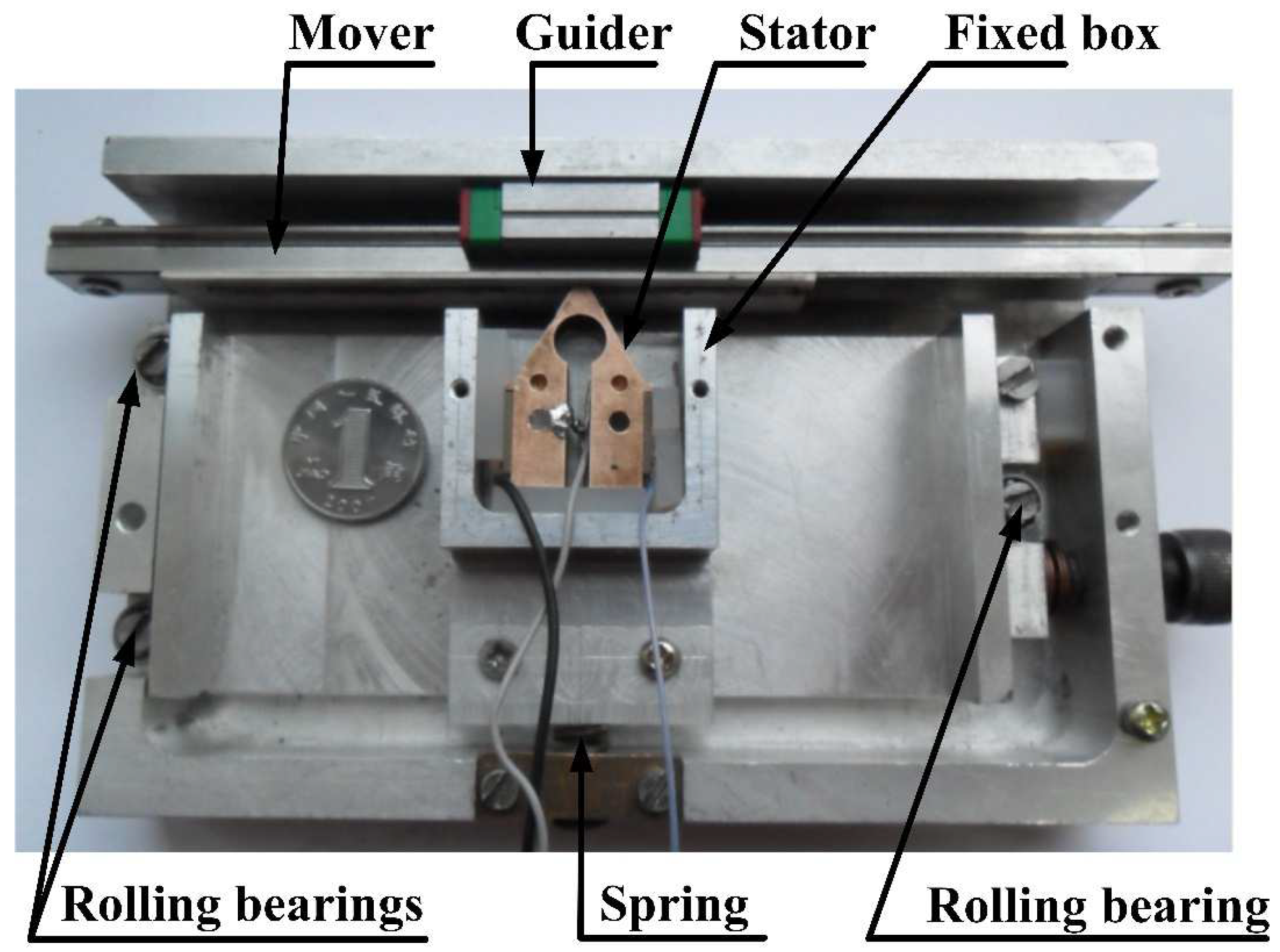
2.1. Construction
- Constant pre-load force being applied to normal contact.Solution: The pre-loaded spring is employed to generate the pre-load force onto the stator.
- The appliance holding the stator is able to balance the shear force between the stator and mover.Solution: The roller bearing device on both sides of the base is installed to balance the force between the stator and mover.
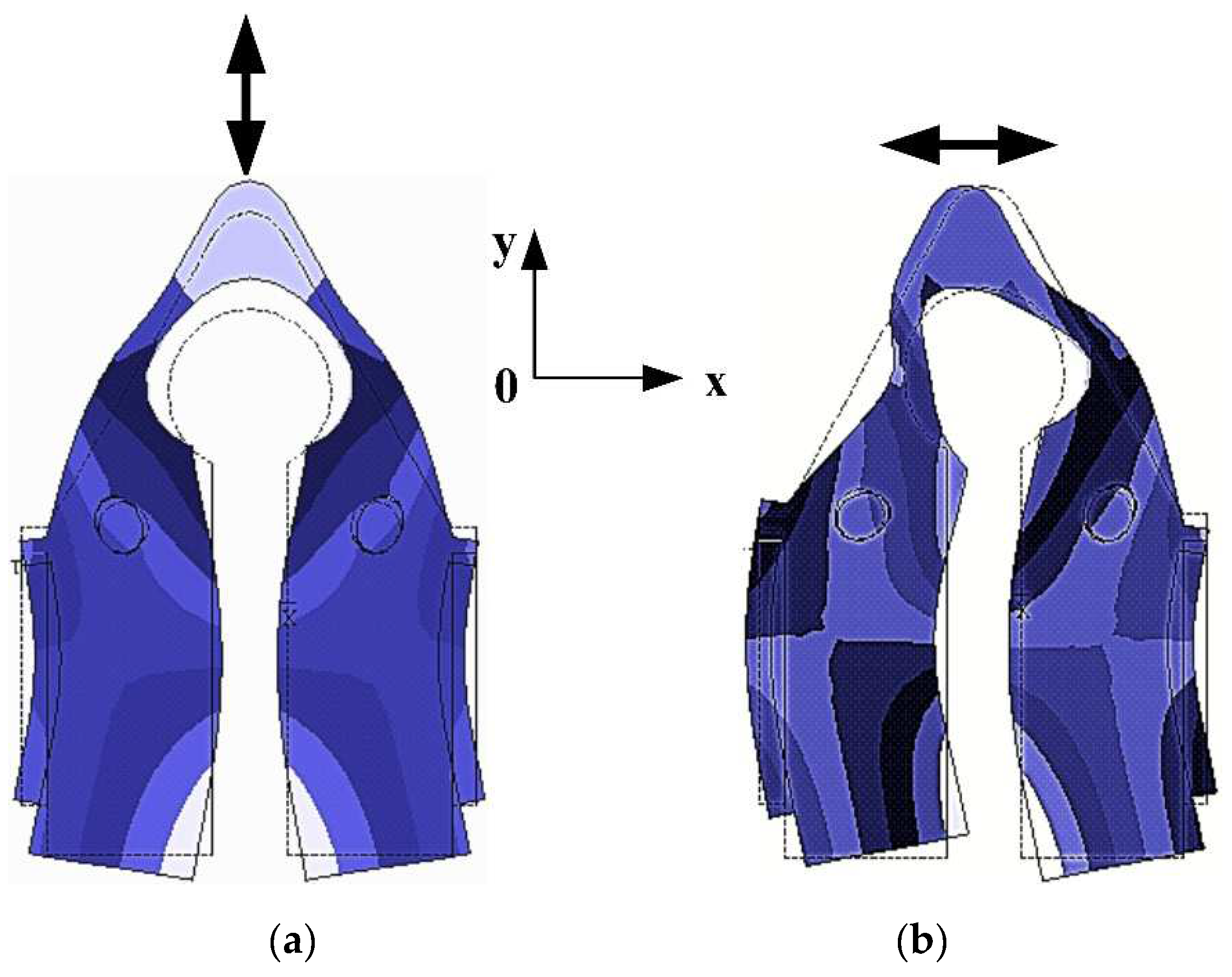
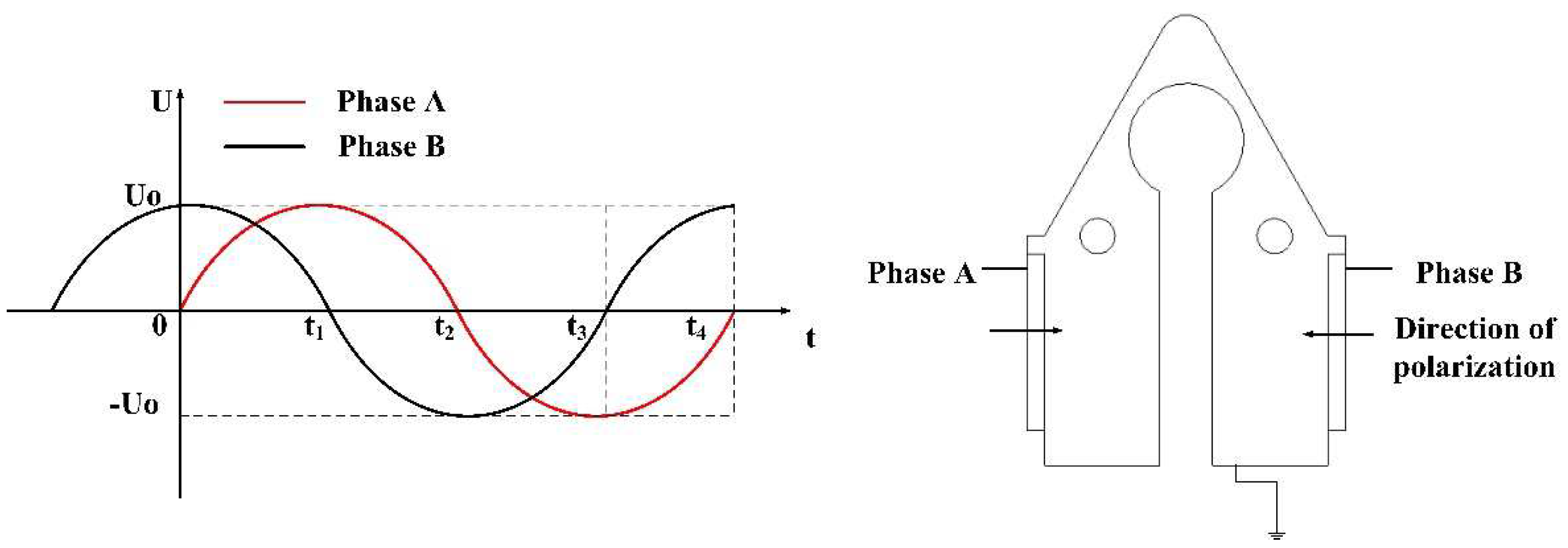
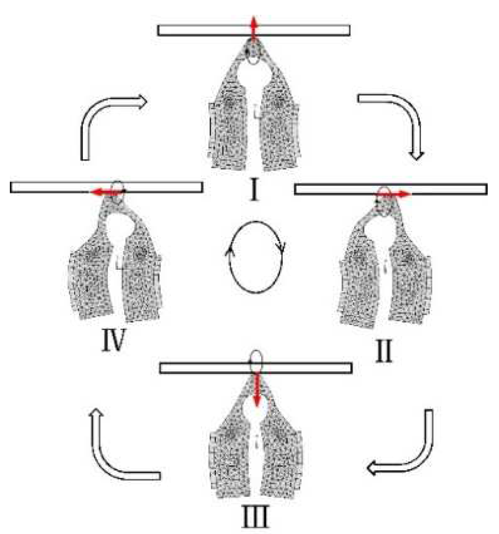
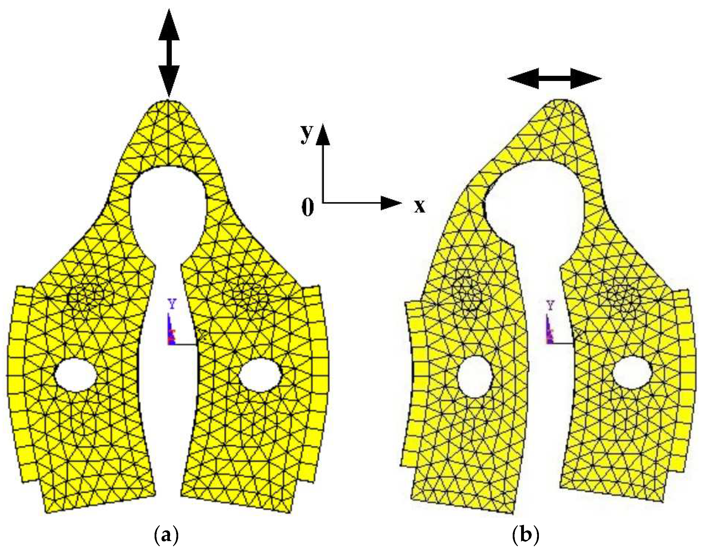
2.2. Working Principle
3. Finite Element Analysis of Stator
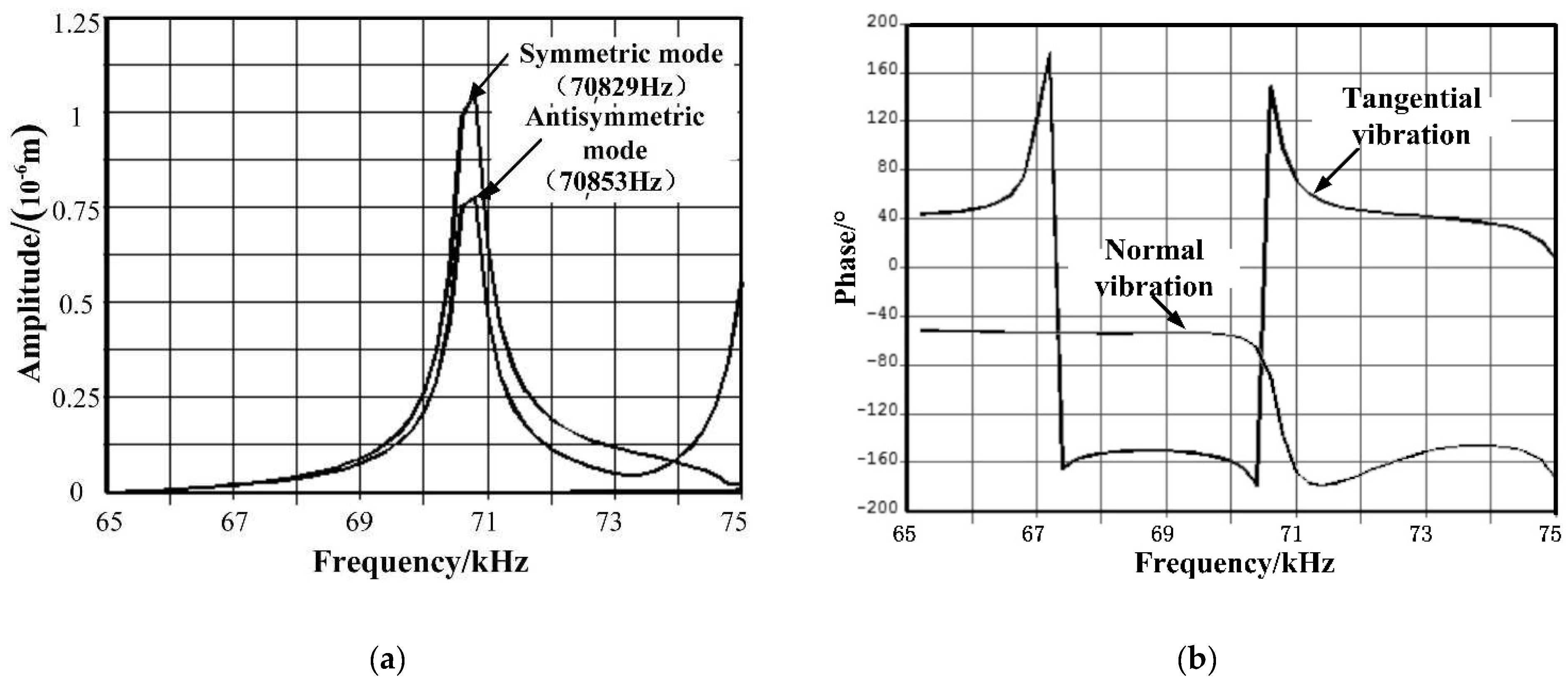
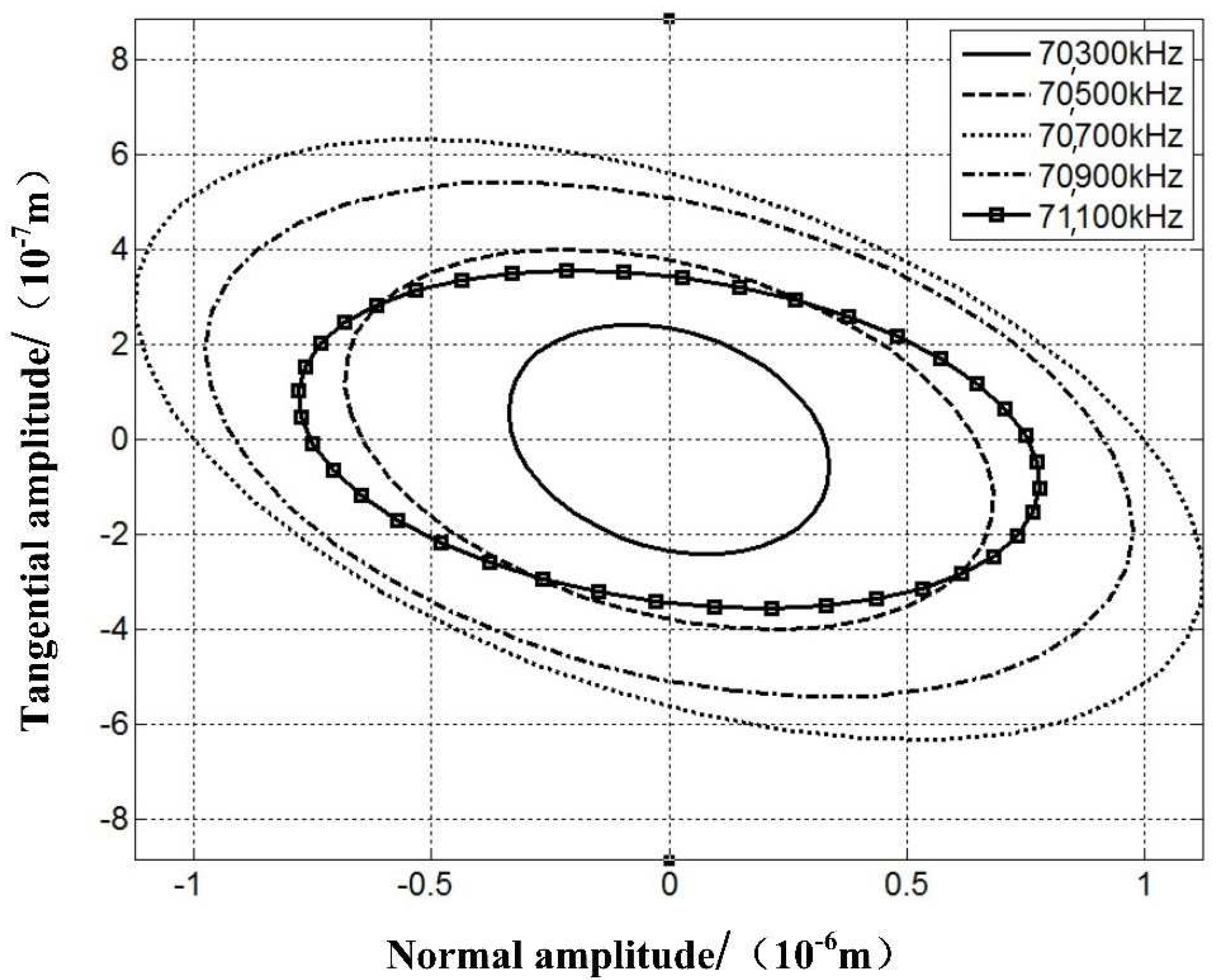
3.1. Modeling and Simulation
3.2. Structure Optimization
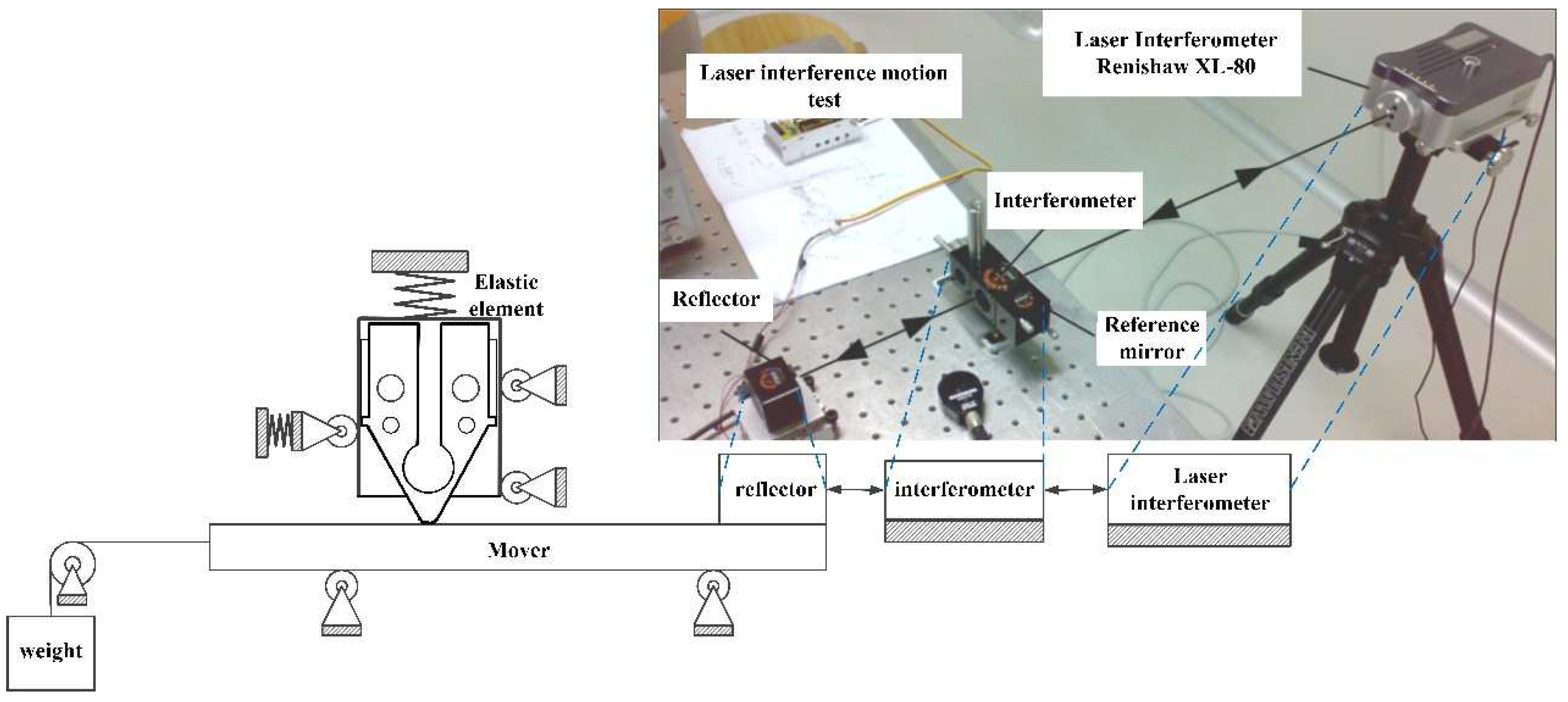
4. Experimental Study
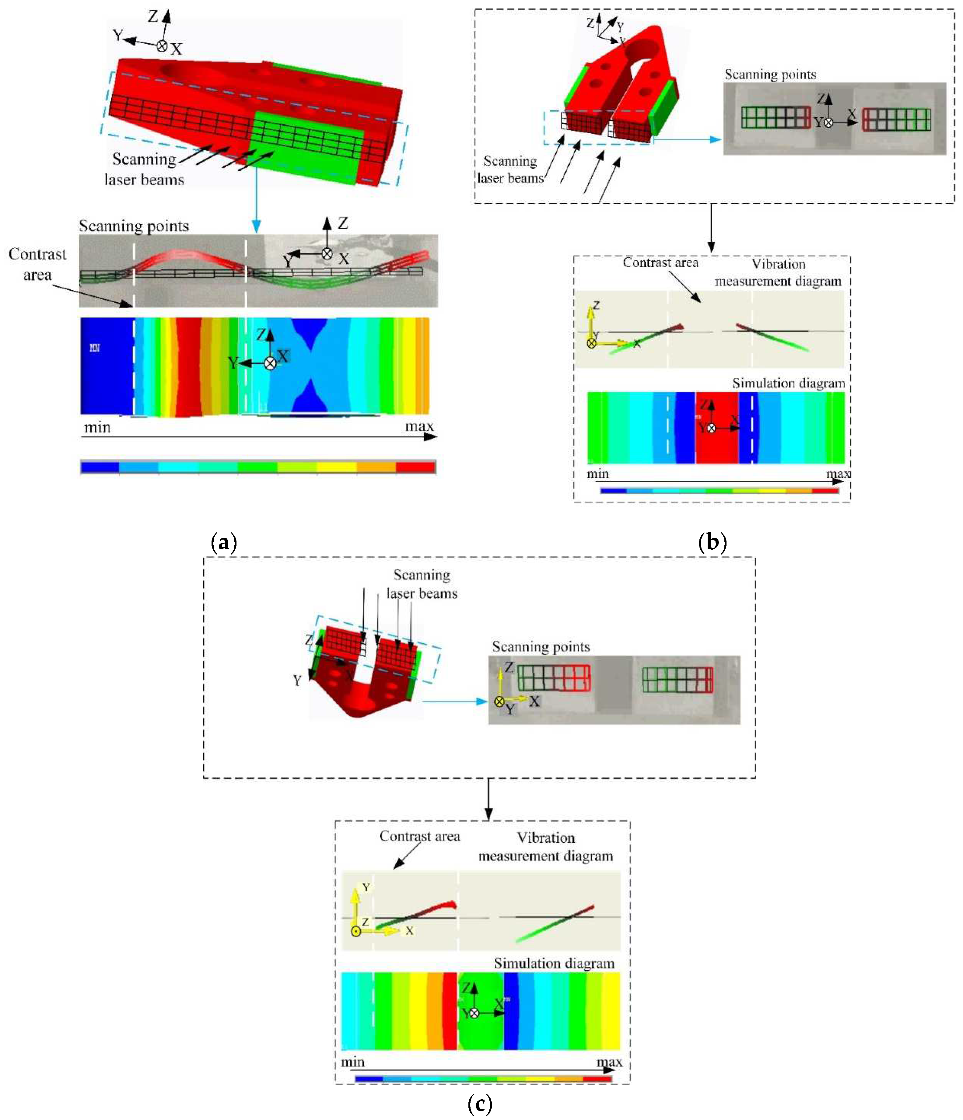
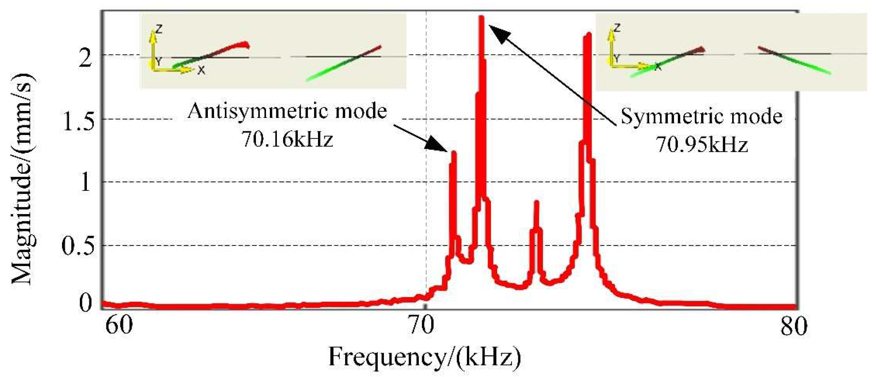
4.1. Vibration Characteristic Experiments
- Set the scanning point on the sample;
- Establish grids on the testing surface of the stator;
- Apply the voltage signal as described in Section 2.2 and assess the motor’s working mode.
- The rubber packer was utilized to stabilize the stator, which in fact simplified the device;
- The boundary condition is not identical for practical experiments and lab simulation;
- Geometrical tolerance during the manufacturing process for the prototype motor can also contribute to this error;
- The material of the prototype can potentially vary from the design in terms of the uniformity and technical parameter.
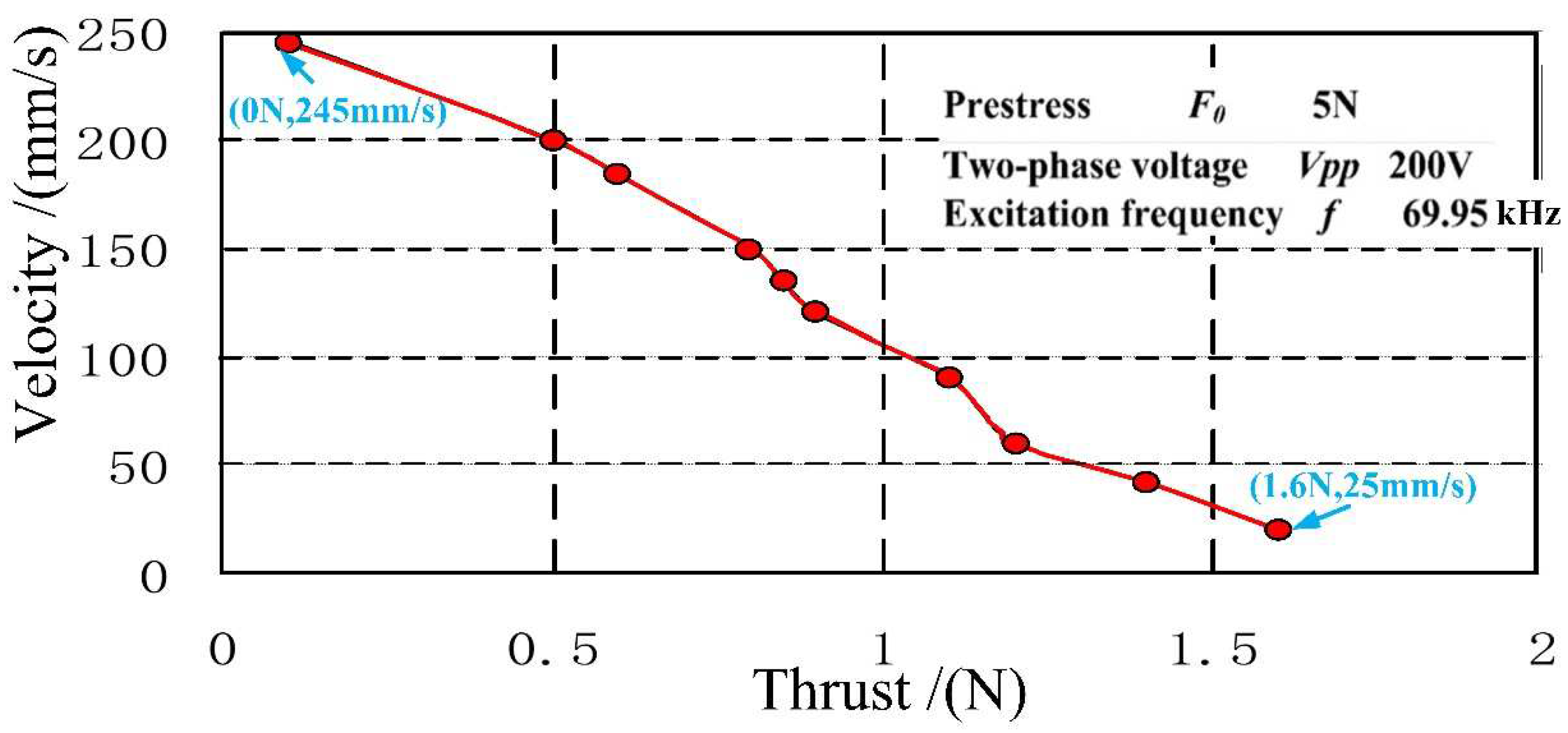
4.2. Performance Evaluation
5. Conclusions
Author Contributions
Funding
Conflicts of Interest
References
- He, H.L.; Wu, D.M.; Liu, W.G. A Linear Piezoelectric Linear Motor Driven by the in-Plane Longitudinal and Bending Vibrations of an H-Shaped Vibrator. Adv. Mater. Res. 2012, 472–475, 2824–2827. [Google Scholar] [CrossRef]
- Huang, J.; Sun, D. Performance Analysis of a Travelling-Wave Ultrasonic Motor under Impact Load. Micromachines 2020, 11, 689. [Google Scholar] [CrossRef]
- Yang, X.; Liu, Y.; Chen, W.; Liu, J. Study on the exciting mode of ultrasonic motor using bending vibration transducer. In Proceedings of the 7th International Power Electronics and Motion Control Conference (IPEMC 2012), Harbin, China, 2–5 June 2012; pp. 59–63. [Google Scholar]
- Fan, P.; Shu, X.; Yuan, T.; Li, C. A novel high thrust-weight ratio linear ultrasonic motor driven by single-phase signal. Rev. Sci. Instrum. 2018, 89, 085001. [Google Scholar] [CrossRef] [PubMed]
- Yan, J.; Liu, Y.; Liu, J.; Xu, D.; Chen, W. The design and experiment of a novel ultrasonic motor based on the combination of bending modes. Ultrasonics 2016, 71, 205–210. [Google Scholar] [CrossRef]
- Yang, X.; Zhang, Q.; Zhou, X. Ultrasonic Motor Using Bending Modes with Single Foot. Adv. Mech. Eng. 2019, 5, 747583. [Google Scholar] [CrossRef]
- Xin, X.; Yu, Y.; Wu, J.; Gao, X.; Li, Z.; Yi, X.; Chen, W.; Dong, S. A ring-shaped linear ultrasonic motor based on PSN-PMS-PZT ceramic. Sens. Actuators A Phys. 2020, 309, 112036. [Google Scholar] [CrossRef]
- Wang, L.; Wielert, T.; Twiefel, J.; Jin, J.; Wallaschek, J. A rod type linear ultrasonic motor utilizing longitudinal traveling waves: Proof of concept. Smart Mater. Struct. 2017, 26, 085013. [Google Scholar] [CrossRef]
- Danhong, L.; Qiuxiang, L.; Bingxun, C.; Chunrong, J.; Xia, H. A single-modal linear ultrasonic motor based on multi vibration modes of PZT ceramics. Ultrasonics 2020, 107, 106158. [Google Scholar]
- Sanikhani, H.; Akbari, J. Design and analysis of an elliptical-shaped linear ultrasonic motor. Sens. Actuators A Phys. 2018, 278, 67–77. [Google Scholar] [CrossRef]
- Li, X.; Chen, Z.; Yao, Z. Contact analysis and performance evaluation of standing-wave linear ultrasonic motors via a physics-based contact model. Smart Mater. Struct. 2019, 28, 015032. [Google Scholar] [CrossRef]
- Deng, Y.; Zhao, G.; Yi, X.; Xiao, W. Contact modeling and input-voltage-region based parametric identification for speed control of a standing wave linear ultrasonic motor. Sens. Actuators A Phys. 2019, 295, 456–468. [Google Scholar] [CrossRef]
- Zhijiang, C.; Xiaotian, L.; Penghong, C.; Guoxi, L.; Shuxiang, D. A standing wave linear ultrasonic motor operating in in-plane expanding and bending modes. Rev. Sci. Instrum. 2015, 86, 035002. [Google Scholar]
- Wan, Z.; Hu, H. Modeling and experimental analysis of the linear ultrasonic motor with in-plane bending and longitudinal mode. Ultrasonics 2014, 54, 921–928. [Google Scholar] [CrossRef]
- Yun, C.; Watson, B.; Friend, J.; Yeo, L. A piezoelectric ultrasonic linear micromotor using a slotted stator. IEEE Trans. Sonics Ultrason. 2010, 57, 1868–1874. [Google Scholar]
- Yang, X.; Liu, Y.; Chen, W.; Liu, J. Miniaturization of a longitudinal–bending hybrid linear ultrasonic motor. Ceram. Int. 2015, 41, S607–S611. [Google Scholar] [CrossRef]
- Tanoue, Y.; Morita, T. Opposing preloads type ultrasonic linear motor with quadruped stator. Sens. Actuators A Phys. 2020, 301, 111764. [Google Scholar] [CrossRef]
- Li, H.; Chen, W.; Tian, X.; Liu, J. An experiment study on temperature characteristics of a linear ultrasonic motor using longitudinal transducers. Ultrasonics 2019, 95, 6–12. [Google Scholar] [CrossRef] [PubMed]
- Díaz-Molina, A.; Ruiz-Díez, V.; Hernando-García, J.; Ababneh, A.; Seidel, H.; Sánchez-Rojas, J.L. Generation of Linear Traveling Waves in Piezoelectric Plates in Air and Liquid. Micromachines 2019, 10, 283. [Google Scholar] [CrossRef] [Green Version]
- Liu, Y.; Chen, W.; Feng, P.; Liu, J. Miniaturization of a U-shape linear piezoelectric motor with double feet. Sens. Actuators A Phys. 2014, 214, 95–100. [Google Scholar] [CrossRef]
- Huang, Z.L.; Chen, W.S. Modeling and Simulation of the Ultrasonic Motor which Using Bending Vibration Transducer. Appl. Mech. Mater. 2014, 628, 240–248. [Google Scholar] [CrossRef]
- Wang, Y.; Chen, Z.; Shi, Y.; Cui, C.; Cheng, F. Longitudinal Composite-Mode Linear Ultrasonic Motor for Motion Servo System of Probe Station. Actuators 2020, 9, 111. [Google Scholar] [CrossRef]
- Le, A.Y.; Mills, J.K.; Benhabib, B. A design methodology for linear ultrasonic motors under contact-based operating conditions. J. Intell. Mater. Syst. Struct. 2016, 27, 39–50. [Google Scholar] [CrossRef]
- Jian, Y.; Yao, Z.; Zhang, B.; Liu, Z. A novel Π-type linear ultrasonic motor driven by a single mode. Rev. Sci. Instrum. 2018, 89, 125010. [Google Scholar] [CrossRef] [PubMed]
- Takano, M.; Takimoto, M.; Nakamura, K. Electrode design of multilayered piezoelectric transducers for longitudinal-bending ultrasonic actuators. Adv. Dairy Sci. Technol. 2011, 32, 100–108. [Google Scholar] [CrossRef] [Green Version]
- Shi, Y.; Zhao, C. A new standing-wave-type linear ultrasonic motor based on in-plane modes. Ultrasonics 2011, 51, 397–404. [Google Scholar] [CrossRef] [PubMed]


| Parameters | d | l | r | w | g | p | h |
|---|---|---|---|---|---|---|---|
| Values | 6.5 | 10.0 | 1.0 | 6.5 | 3.0 | 12.0 | 18.38 |
Publisher’s Note: MDPI stays neutral with regard to jurisdictional claims in published maps and institutional affiliations. |
© 2021 by the authors. Licensee MDPI, Basel, Switzerland. This article is an open access article distributed under the terms and conditions of the Creative Commons Attribution (CC BY) license (https://creativecommons.org/licenses/by/4.0/).
Share and Cite
Li, J.; Wang, Y.; Chen, Z.; Cheng, F.; Yu, Q. A Compact Linear Ultrasonic Motor Composed by Double Flexural Vibrator. Micromachines 2021, 12, 958. https://doi.org/10.3390/mi12080958
Li J, Wang Y, Chen Z, Cheng F, Yu Q. A Compact Linear Ultrasonic Motor Composed by Double Flexural Vibrator. Micromachines. 2021; 12(8):958. https://doi.org/10.3390/mi12080958
Chicago/Turabian StyleLi, Jiayin, Yin Wang, Ziyan Chen, Fang Cheng, and Qing Yu. 2021. "A Compact Linear Ultrasonic Motor Composed by Double Flexural Vibrator" Micromachines 12, no. 8: 958. https://doi.org/10.3390/mi12080958