
Shape Memory Alloy Capsule Micropump for Drug Delivery Applications


Abstract
:1. Introduction
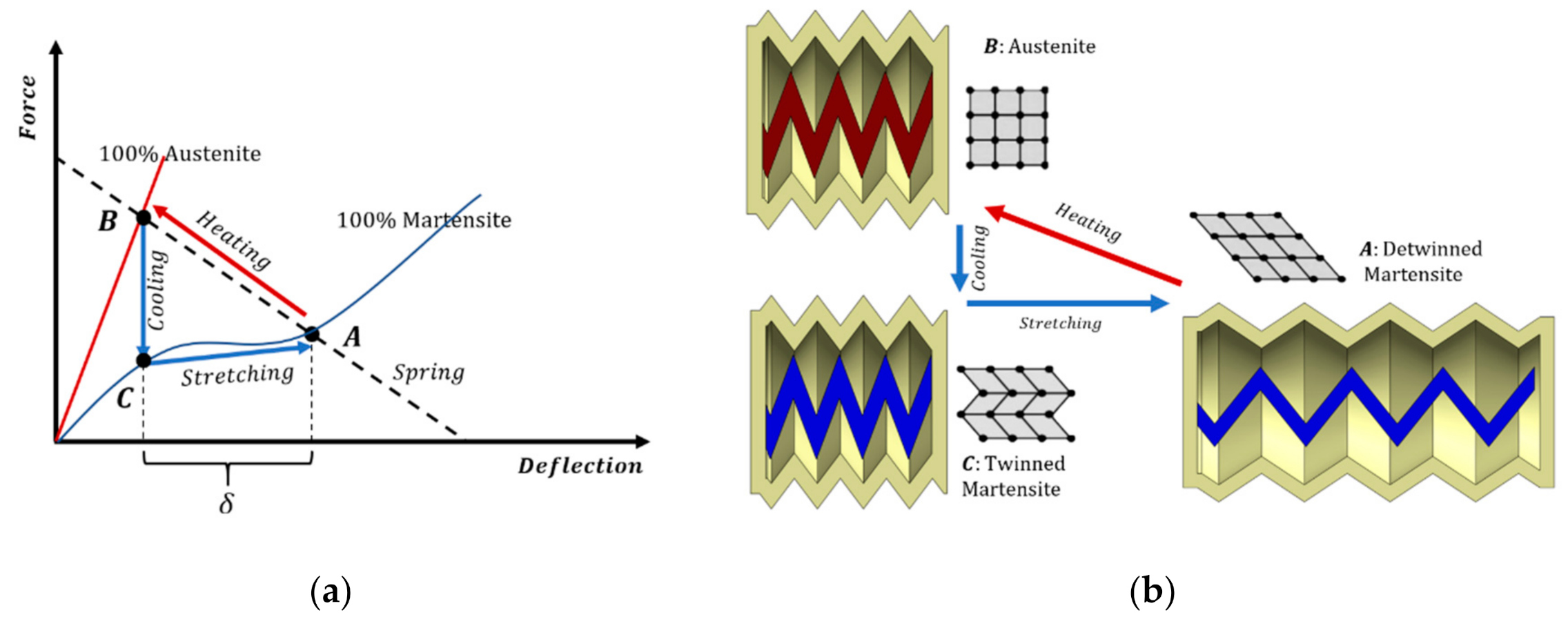
2. Principle of Operation
2.1. Pump Chararacteristics
2.2. Pump Operation
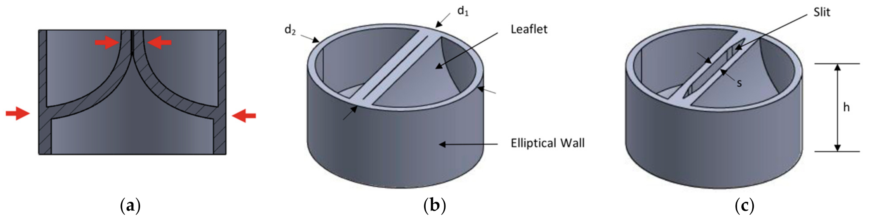
2.3. Valve Design
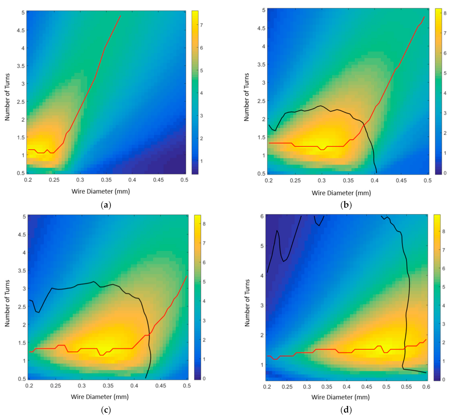
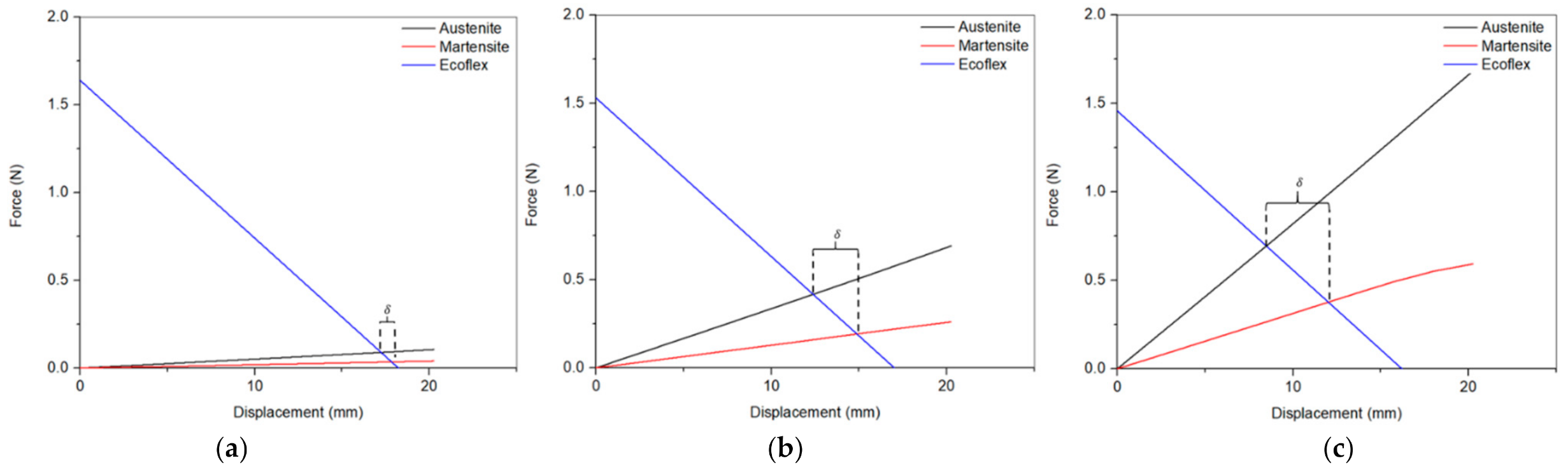
3. Modeling and Parametric Study of the SMA Pump
4. Materials and Methods
4.1. Materials
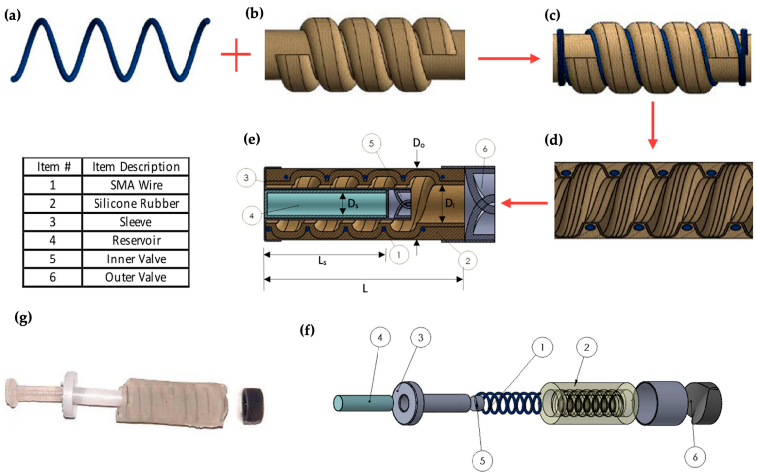
4.2. Pump Fabrication
4.3. Characterization
5. Results and Discussion
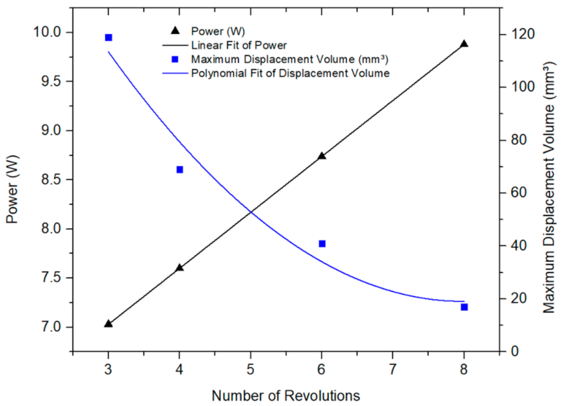
5.1. Maximum Displaced Volume
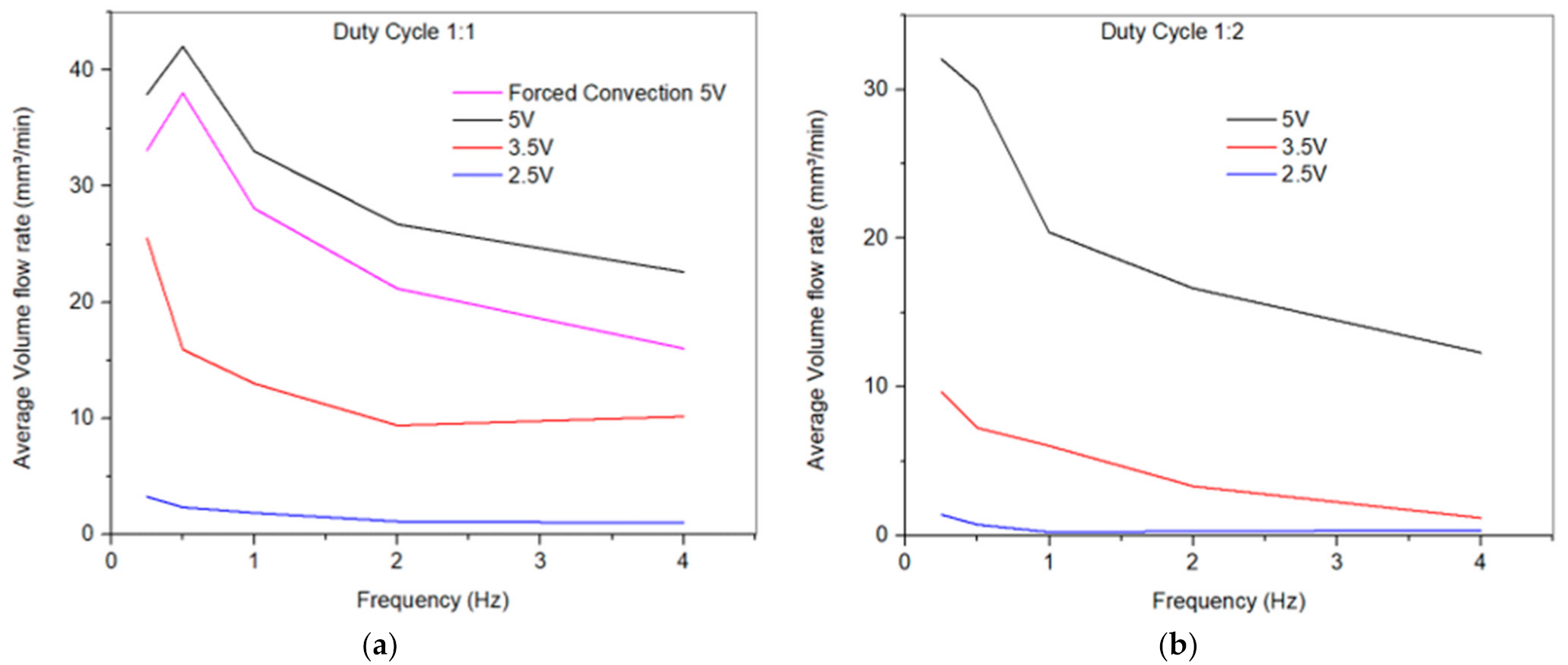
5.2. Effect of Drive Frquency on Flow Rate
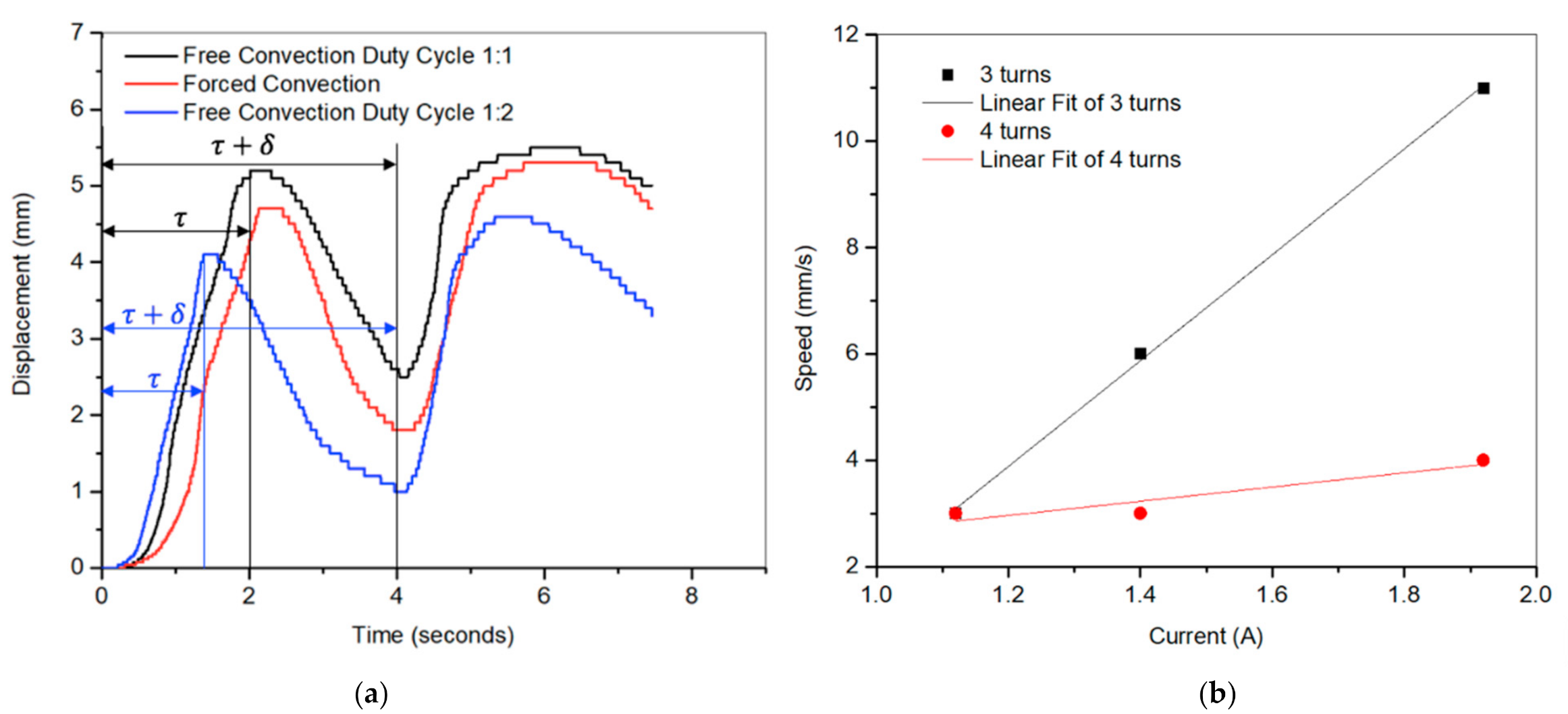
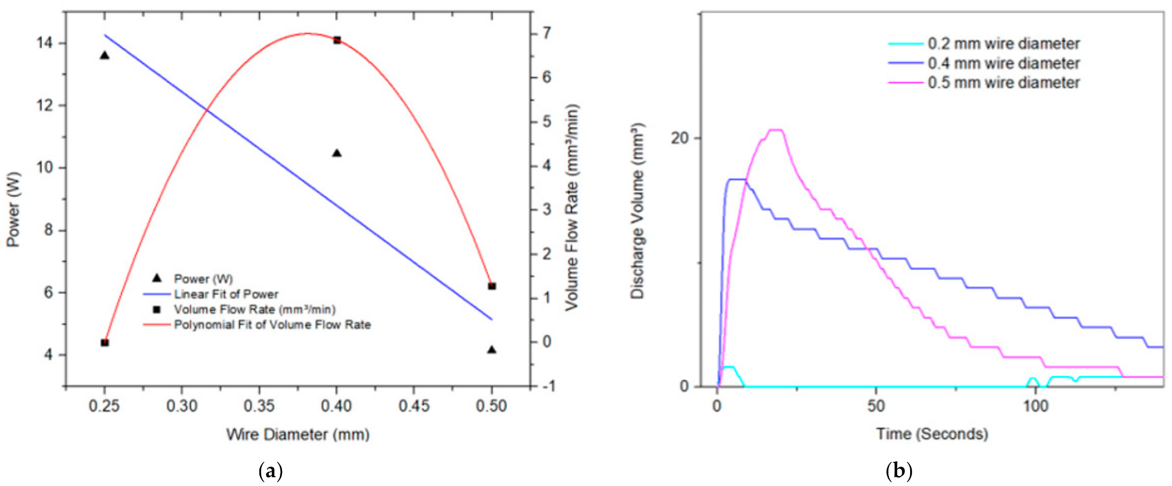
5.3. Effect of Wire Diameter and Number of Turns on the Flow Rate
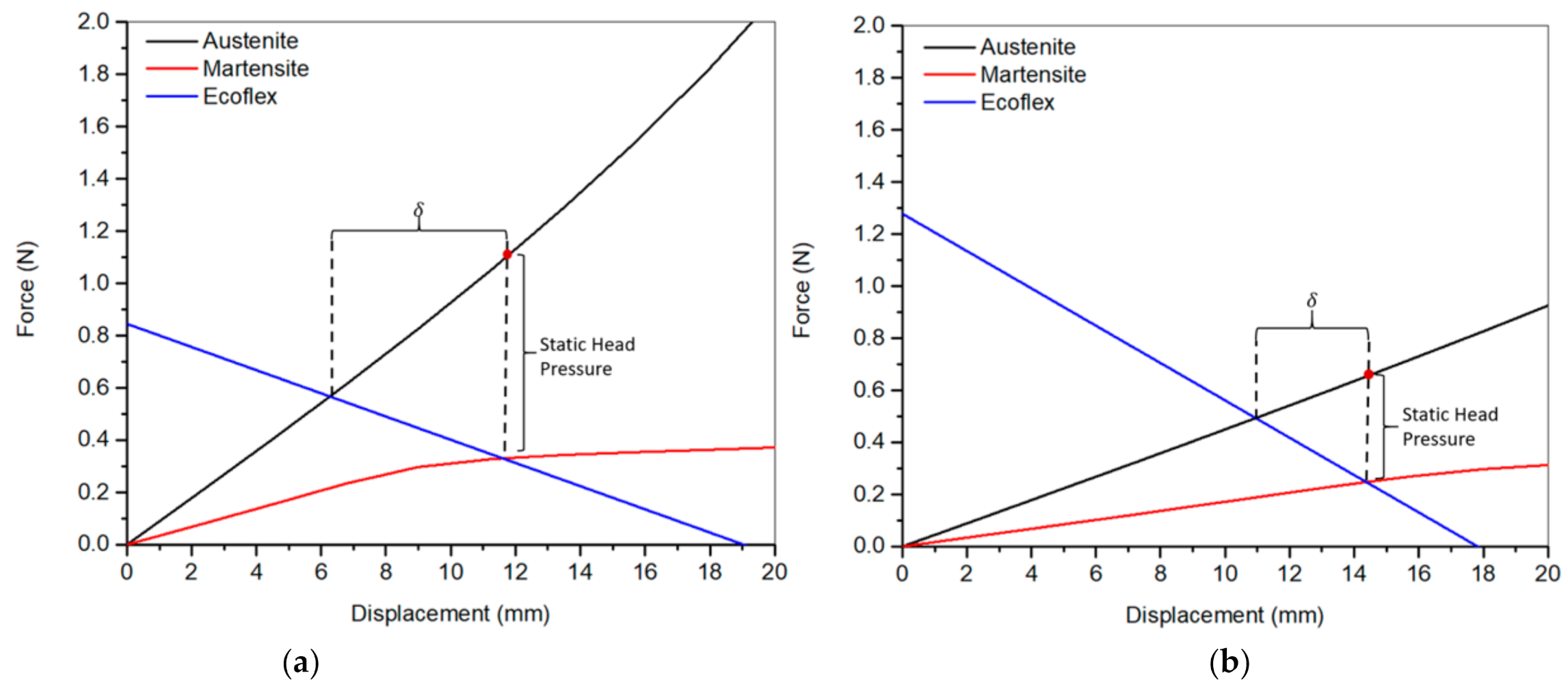
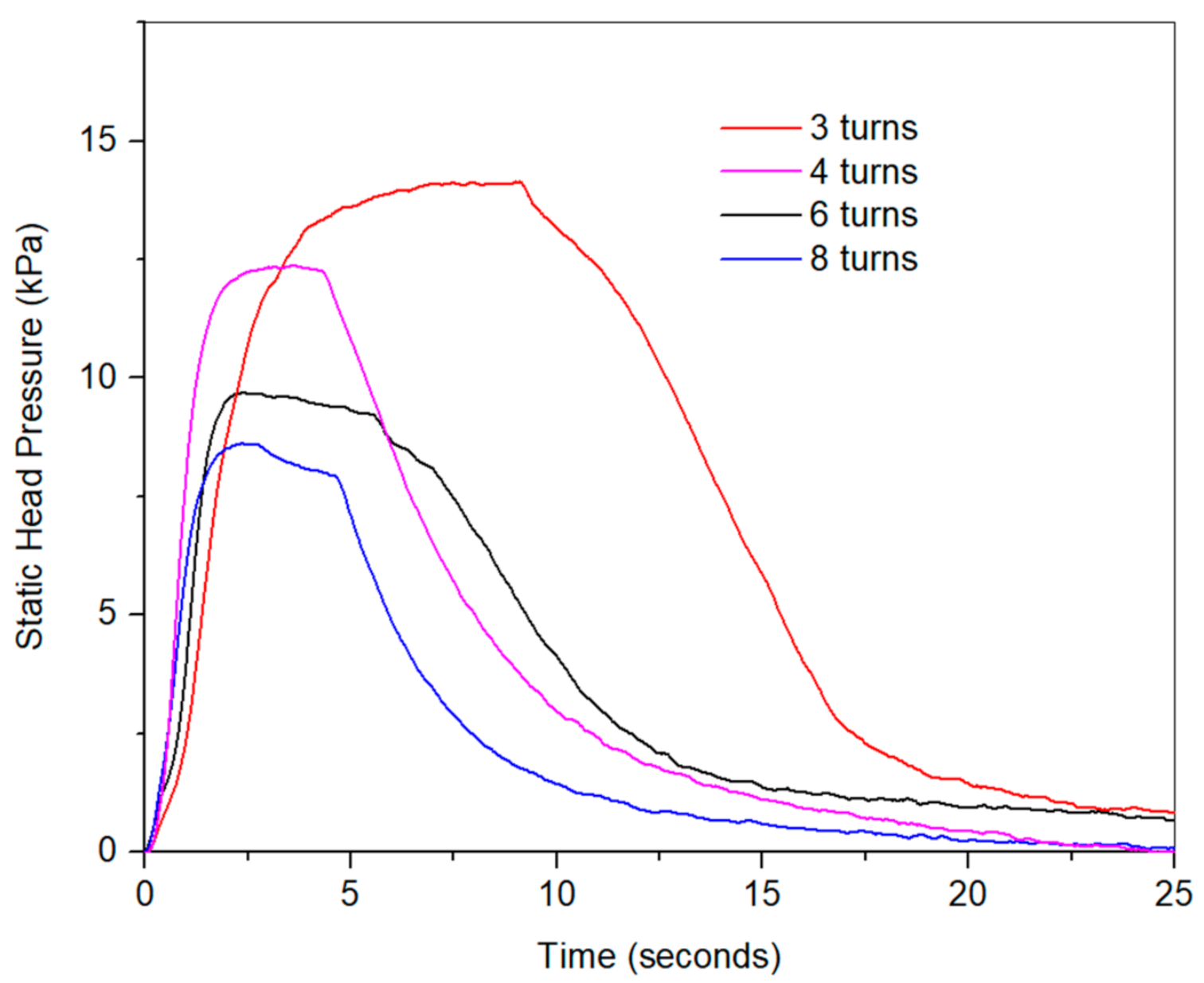
5.4. Effect of Number of Turns on Static Pressure Head
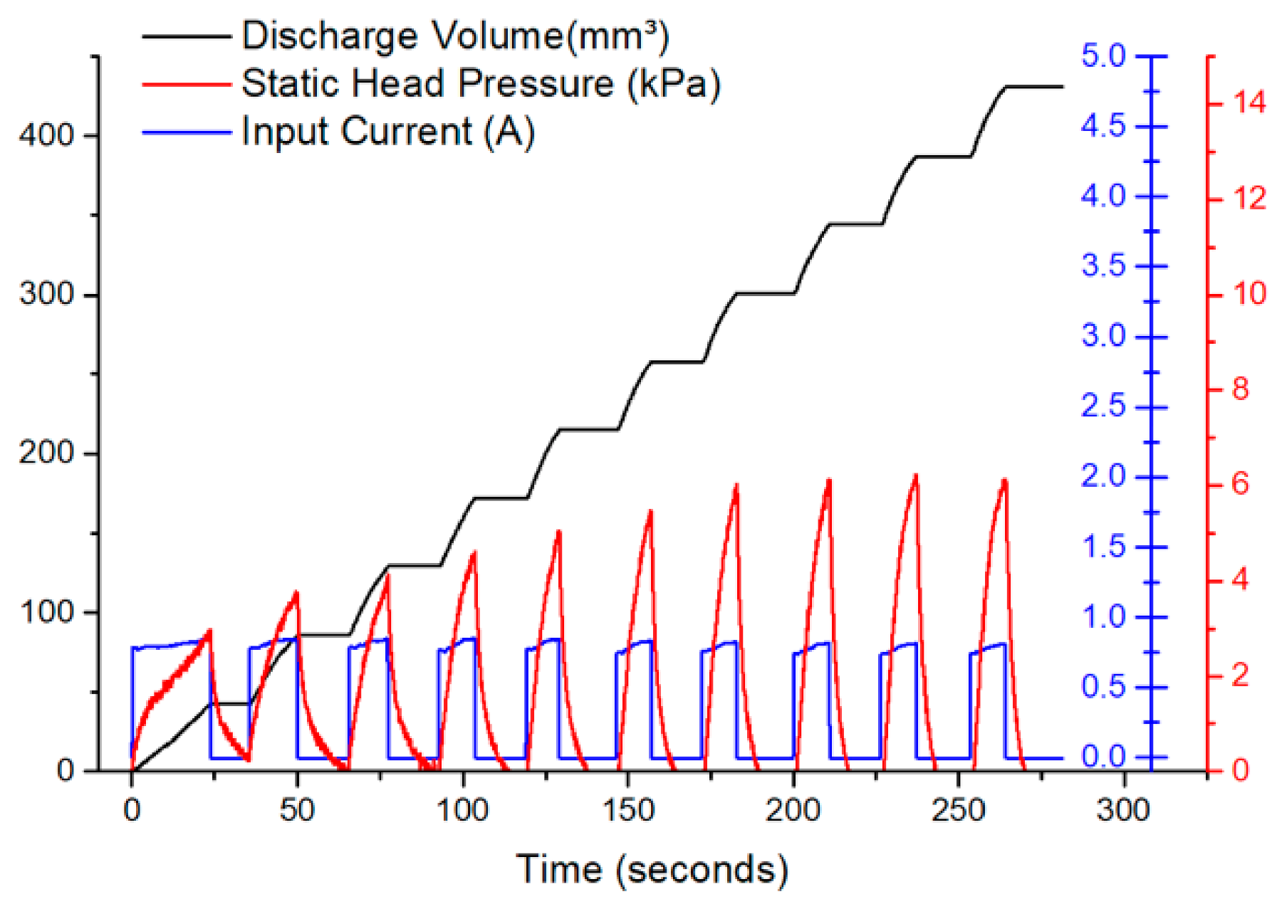
5.5. Pump Operation
6. Conclusions
7. Patents
Author Contributions
Funding
Acknowledgments
Conflicts of Interest
References
- Mobaraki, M.; Soltani, M.; Zare Harofte, S.; LZoudani, E.; Daliri, R.; Aghamirsalim, M.; Raahemifar, K. Biodegradable nanoparticle for cornea drug delivery: Focus review. Pharmaceutics 2020, 12, 1232. [Google Scholar] [CrossRef] [PubMed]
- Singh, M.N.; Hemant, K.S.Y.; Ram, M.; Shivakumar, H.G. Microencapsulation: A promising technique for controlled drug delivery. Res. Pharm. Sci. 2010, 5, 65. [Google Scholar] [PubMed]
- Phanindra, B.; Moorthy, B.K.; Muthukumaran, M. Recent advances in mucoadhesive/bioadhesive drug delivery system: A review. Int. J. Pharm. Med. Bio. Sci. 2013, 2, 68–84. [Google Scholar]
- Weinberg, B.D.; Blanco, E.; Gao, J. Polymer implants for intratumoral drug delivery and cancer therapy. J. Pharm. Sci. 2008, 97. [Google Scholar] [CrossRef] [PubMed]
- Al Hanbali, O.A.; Khan, H.M.S.; Sarfraz, M.; Arafat, M.; Ijaz, S.; Hameed, A. Transdermal patches: Design and current approaches to painless drug delivery. Acta Pharm. 2019, 69. [Google Scholar] [CrossRef] [Green Version]
- Rajgor, N.; Patel, M.; Bhaskar, V.H. Implantable drug delivery systems: An overview. Syst. Rev. Pharm. 2011, 2. [Google Scholar] [CrossRef]
- Verma, R.; Garg, S. Drug delivery technologies and future directions. Pharm. Technol. 2001, 25, 1–14. [Google Scholar]
- Cobo, A.; Sheybani, R.; Tu, H.; Meng, E. A wireless implantable micropump for chronic drug infusion against cancer. Sens. Actuators A Phys. 2016, 239. [Google Scholar] [CrossRef] [PubMed] [Green Version]
- Mahnama, A.; Nourbakhsh, A.; Ghorbaniasl, G. A survey on the applications of implantable micropump systems in drug delivery. Curr. Drug Deliv. 2014, 11. [Google Scholar] [CrossRef]
- Sideris, E.A.; de Lange, H.C. Pumps operated by solid-state electromechanical smart material actuators—A review. Sens. Actuators A Phys. 2020, 307. [Google Scholar] [CrossRef]
- Serry, M.Y.; Moussa, W.A.; Raboud, D.W. Finite element investigation of the behavior of SMA damage-control smart system. Smart Mater. Struct. 2007, 16. [Google Scholar] [CrossRef]
- Serry, M.Y.; Raboud, D.W.; Moussa, W.A. Nonlinear coupled field finite element procedure for modeling of shape memory alloy components in multi-physics applications. Mech. Adv. Mater. Struct. 2010, 17. [Google Scholar] [CrossRef]
- Sassa, F.; Al-Zain, Y.; Ginoza, T.; Miyazaki, S.; Suzuki, H. Miniaturized shape memory alloy pumps for stepping microfluidic transport. Sens. Actuators B Chem. 2012, 165. [Google Scholar] [CrossRef]
- Lara-Quintanilla, A.; Bersee, H.E.N. Active cooling and strain-ratios to increase the actuation frequency of SMA wires. Shape Mem. Superelast. 2015, 1. [Google Scholar] [CrossRef] [Green Version]
- Benard, W.L.; Kahn, H.; Heuer, A.H.; Huff, M.A. Thin-film shape-memory alloy actuated micropumps. J. Microelectromech. Syst. 1998, 7. [Google Scholar] [CrossRef]
- Xu, D.; Wang, L.; Ding, G.; Zhou, Y.; Yu, A.; Cai, B. Characteristics and fabrication of NiTi/Si diaphragm micropump. Sens. Actuators A Phys. 2001, 93. [Google Scholar] [CrossRef]
- Makino, E.; Mitsuya, T.; Shibata, T. Fabrication of TiNi shape memory micropump. Sens. Actuators A Phys. 2001, 88. [Google Scholar] [CrossRef]
- Guo, S.; Sun, X.; Ishii, K.; Guo, J. SMA actuator-based novel type of peristaltic micropump. In Proceedings of the 2008 International Conference on Information and Automation, Changsha, China, 20–23 June 2008. [Google Scholar] [CrossRef]
- Xuesong, S.; Guo, S.; Xiaonan, Y. A Novel type of peristaltic micropump for biomedical applications. In Proceedings of the 2008 IEEE International Conference on Mechatronics and Automation, Takamatsu, Japan, 5–8 August 2008. [Google Scholar] [CrossRef]
- Sun, X.; Hao, Y.; Guo, S.; Ye, X.; Yan, X. The development of a new type of compound peristaltic micropump. In Proceedings of the 2008 IEEE International Conference on Robotics and Biomimetics, Bangkok, Thailand, 22–25 February 2009; pp. 698–702. [Google Scholar]
- Ikuta, K.; Takahashi, A.; Ikeda, K.; Maruo, S. Fully integrated micro biochemical laboratory using biochemical IC chips—Cell-free protein synthesis by using a built-in micropump chip. In Proceedings of the Sixteenth Annual International Conference on Micro Electro Mechanical Systems, Kyoto, Japan, 23 January 2003. [Google Scholar]
- Ikuta, K.; Hasegawa, T.; Adachi, T. SMA micro pump chip to flow liquids and gases. In Proceedings of the International Conference on Shape Memory and Superelastic Technologies, Tsukuba, Japan, 2–5 December 2008. [Google Scholar] [CrossRef]
- Liang, C.; Rogers, C.A. One-Dimensional thermomechanical constitutive relations for shape memory materials. J. Intell. Mater. Syst. Struct. 1990, 1. [Google Scholar] [CrossRef]
- Brinson, L.C. One-dimensional constitutive behavior of shape memory alloys: Thermomechanical derivation with non-constant material functions and redefined martensite internal variable. J. Intell. Mater. Syst. Struct. 1993, 4. [Google Scholar] [CrossRef]
- An, S.M.; Ryu, J.; Cho, M.; Cho, K.J. Engineering design framework for a shape memory alloy coil spring actuator using a static two-state model. Smart Mater. Struct. 2012, 21. [Google Scholar] [CrossRef]
- Bae, W.J.; Choi, J.B.; Kim, K.S.; Kim, S.J.; Cho, H.J.; Ha, U.S.; Hong, S.H.; Lee, J.Y.; Kim, S.W. AB168. Evaluation of the biocompatibility of packing materials for a catheter. Transl. Androl. Urol. 2015, 4 (Suppl. 1). [Google Scholar] [CrossRef]
- Son, J.; Jung, S.; Park, J.M.; Wu, H.-G.; Kim, J.-I. Evaluation of platinum-catalyzed silicones for fabrication of biocompatible patient-specific elastic bolus. Res. Sq. 2020. [Google Scholar] [CrossRef]
- Ecoflex Manufacturer’s (Smooth-on) Data Sheet. Available online: https://www.smooth-on.com/tb/files/ECOFLEX_SERIES_TB.pdf (accessed on 30 March 2021).


| Parameter | Definition | Value * |
|---|---|---|
| Fraction of detwinned martensite | Varies from 0–1 | |
| Critical starting and ending shear stresses | 105 and 215 MPa | |
| Maximum residual strain | 0.056 | |
| Shear modulus of martensite and austenite phases | 5.65 and 18.3 GPa |
| Material Property | Value |
|---|---|
| Mixed Viscosity [Pa·s] | 3 |
| Specific Gravity [g/cm3] | 1.07 |
| Shore Hardness [ASTM D-2240] | 00–30 |
| Tear Strength [N/mm] | 6.65 |
| Tensile Strength [MPa] | 1.38 |
| Elongation at break [%] | 900 |
| Shrinkage [mm/mm] | <0.001 |
| Curing Time at Room Temperature [h] | 4 |
| Reported Work | Pump Volume (mm3) | Power (W) | Max Stroke (mm) | SHP * kPa | Transition Temp (°C) | Max Flow Rate (μL/min) | Max Flow Rate Per Watt (μL/(watt·min)) | Max Flow Rate Per Pump Volume (μL/(min·mm3)) | Pump Design |
|---|---|---|---|---|---|---|---|---|---|
| This Work | 424.7 | 7.1 | 5.6 | 14 | 45 | 2524 | 356.26 | 5.94 | Capsule (New) |
| 4.2 | 45 | 1531 | 364.52 | 3.60 | |||||
| 2.9 | 45 | 195 | 66.96 | 0.46 | |||||
| Benard 1998 [15] | 35.28 | - | 0.53 | 60–75 | 50 | - | 1.42 | Diaphragm | |
| Sassa 2011 [13] | 27.61 | 2.8 | 1.8 | ||||||
| Guo 2008 [18] | 40,500 | 3 | 8 | - | 80 | 1000 | 333.33 | 0.02 | Peristaltic |
| Dong 2001 [16] | 54 | 1.1 | 0.006 | - | 70–75 | 340 | 321.97 | 6.30 | Membrane |
| Makino 2001 [17] | 280 | 0.095 | - | 80 | 4.8 | - | 0.02 | Membrane | |
| Sun 2008 [20] | 67,200 | 1.4 | 5.8 | 50 | 1000 | 694.44 | 0.01 | Peristaltic |
Publisher’s Note: MDPI stays neutral with regard to jurisdictional claims in published maps and institutional affiliations. |
© 2021 by the authors. Licensee MDPI, Basel, Switzerland. This article is an open access article distributed under the terms and conditions of the Creative Commons Attribution (CC BY) license (https://creativecommons.org/licenses/by/4.0/).
Share and Cite
Kotb, Y.; Elgamal, I.; Serry, M. Shape Memory Alloy Capsule Micropump for Drug Delivery Applications. Micromachines 2021, 12, 520. https://doi.org/10.3390/mi12050520
Kotb Y, Elgamal I, Serry M. Shape Memory Alloy Capsule Micropump for Drug Delivery Applications. Micromachines. 2021; 12(5):520. https://doi.org/10.3390/mi12050520
Chicago/Turabian StyleKotb, Youssef, Islam Elgamal, and Mohamed Serry. 2021. "Shape Memory Alloy Capsule Micropump for Drug Delivery Applications" Micromachines 12, no. 5: 520. https://doi.org/10.3390/mi12050520