Technical Note

Multi-Aperture Joint-Encoding Fourier Ptychography for a Distributed System

1
School of Optoelectronic Engineering, Xidian University, Xi’an 710071, China
2
Xi’an Key Laboratory of Computational Imaging, Xi’an 710071, China
3
CAS Key Laboratory of Space Precision Measurement Technology, Xi’an 710119, China
4
National Key Laboratory of Infrared Detection Technologies, Shanghai 200083, China
5
Xian Research Institute of Surveying and Mapping, Xi’an 710054, China
*
Author to whom correspondence should be addressed.
Remote Sens. 2024, 16(6), 1017; https://doi.org/10.3390/rs16061017
Submission received: 3 January 2024 / Revised: 29 February 2024 / Accepted: 6 March 2024 / Published: 13 March 2024
(This article belongs to the Special Issue Laser and Optical Remote Sensing for Planetary Exploration)

Abstract

:
High-resolution infrared remote sensing imaging is critical in planetary exploration, especially under demanding engineering conditions. However, due to diffraction, the spatial resolution of conventional methods is relatively low, and the spatial bandwidth product limits imaging systems’ design. Extensive research has been conducted with the aim of enhancing spatial resolution in remote sensing using a multi-aperture structure, but obtaining high-precision co-phase results using a sub-aperture remains challenging. A new high-resolution imaging method utilizing multi-aperture joint-encoding Fourier ptychography (JEFP) is proposed as a practical means to achieve super-resolution infrared imaging using distributed platforms. We demonstrated that the JEFP approach achieves pixel super-resolution with high efficiency, without requiring subsystems to perform mechanical scanning in space or to have high position accuracy. Our JEFP approach extends the application scope of Fourier ptychographic imaging, especially in distributed platforms for planetary exploration applications.

1. Introduction

The utilization of infrared remote sensing is crucial in the field of planetary exploration due to its ability to gather a wealth of data on planetary atmospheres and surface characteristics. However, remote sensing in planetary exploration needs to meet challenging requirements, such as lighter and smaller payloads with lower power consumption and a long-life payload design [1]. The successful execution of high-resolution planetary exploration often depends on the utilization of large-aperture remote sensing systems [2]. As the aperture of large traditional telescopes such as the Harper telescope continues to increase, the processing and launch of satellite payloads may pose technical obstacles. To address the challenges related to launching a telescope with a large aperture, NASA proposed the use of splicing technology for the JWST [3].
The resolution of an optical system is not only limited by the Abbe diffraction limit but also determined by the detector pixel size. In recent years, the size of detectors has been progressively reduced. However, the trend of pixel size reduction (especially for infrared detectors) has slowed down significantly due to constraints in the fabrication process and other conditions. On the other hand, the physical reduction in pixel size not only leads to a decrease in luminous flux at the expense of the signal-to-noise ratio (SNR) but also imposes higher requirements on the signal pathway, data storage, and processing; moreover, dark current, pixel delineation, and unit cell readout capacity also constrain further reductions in pixel size [4]. In imaging systems where the focal plane detector array is not sufficiently dense to meet the Nyquist criterion, the resulting images are degraded due to aliasing effects, which is a common problem among staring infrared imaging systems [5]. How to mitigate the impact of the pixel size of such infrared remote sensing systems to obtain high-resolution images with reduced aliasing is an urgent problem to be solved in the field of planet exploration.
Pixel super-resolution is a technique for recovering high-resolution images from single or multiple low-resolution images (under-sampling), and methods including it can be broadly classified into three categories at present.
The first class of methods includes single-frame-based restoration methods, which consist of the reconstruction of a high-resolution image from a single low-resolution image and were first proposed by Goodman and Harris [6]. Generally, in such methods, the interpolation of the captured image is based on some kind of a priori physical model of the scene. In recent years, machine learning has further fueled the development of single-frame super-resolution techniques [7,8]. However, while such methods are able to achieve a perceptual increase in resolution, it is often difficult to guarantee high-resolution realistic detail in the target image.
The second class of methods includes multi-frame-based restoration methods, which consist of the recovery of a high-resolution version of a low-resolution scene by acquiring multiple images. In these methods, micro-scanning is typically employed to acquire multiple low-resolution images with sub-pixel shifts; the images are then combined with an iterative algorithm to reconstruct a high-resolution image. There is a fundamental limitation to this type of approach: the constraints on super-resolution reconstruction rapidly weaken with increasing magnification (typically no more than 1.5 times) [9,10] due to problems such as non-uniform sampling [11] during image acquisition and alignment errors [12] during image processing.
The third class of methods includes coding-based pixel super-resolution imaging methods [13,14,15], which allow the spectral aliasing problem caused by image elements to be overcome by setting a coding mask, thus overcoming the limitation of detector spatial sampling and achieving image de-aliasing. Among them, the Fourier ptychography-based coding method consists of multiple-image aliasing acquisition by using different aperture codes [16] and the iterative reconstruction of the target in the frequency domain using Fourier ptychography, ultimately allowing for the recovery of high-frequency detailed information that exceeds the pixel limit. This method can improve optical resolution very effectively, but the aperture modulation needs to be changed to achieve the complete acquisition of spectral information; therefore, its imaging time efficiency is relatively low. Therefore, it is still difficult to meet the stringent dynamic and temporal requirements of satellite missions and other missions.
In planetary and space sciences, image super-resolution techniques improve surface feature identification in planetary observation missions and data quality to support human exploration missions. The relevant super-resolution methods mainly include methods based on traditional image computation and deep learning. The former are used for extracting non-redundant, sub-pixel information from multi-frame images [17]; however, they also face the problems of computational speed and the fixed orbit limitation of the camera load. Deep learning-based methods, on the other hand, are data-driven approaches used to improve the spatial resolution of images while maintaining or enhancing their details and quality; however, such methods also suffer from issues such as synthetic textures, the realism of the results, the limitations of the training data, and the generalization and interpretability of the models [18,19].
In recent decades, the space-based electro-optical distributed aperture system (EODAS) [20] and synthetic-aperture systems [21,22,23,24] have seen rapid development, achieving better imaging performance with on-orbit self-assembly of relatively small mirror segments mounted on separate low-cost spacecraft [25]. However, it cannot be ignored that the high precision of mirror mounting and the difficulty of sub-aperture co-phase adjustment cause significant problems from fabrication to launch in orbit in such space-based systems.
Herein, we introduce a new pixel super-resolution method termed JEFP which encodes the spatial frequency of an under-sampled imaging system by means of an elliptical aperture and performs spectral reconstruction from acquired low-resolution image sequences to improve the resolution of the pixelized imaging system. Further, our proposed JEFP scheme, which can be extended to distributed systems, aims to maximize the benefits of utilizing distributed platforms for high-resolution imaging. Different from traditional pixel super-resolution methods and traditional synthetic-aperture imaging techniques, our method does not rely on sophisticated mechanical scanning devices to obtain redundant information to perform the super-resolution task. Significantly, the proposed method does not rely on the accurate position information of the distributed platform, which shifts the whole focus to the subsequent computational processing of the data. In addition, the proposed distributed system greatly improves the collection efficiency of the system, making it more adaptable as well as more flexible.

2. Methods

To better understand the whole process of our multi-aperture JEFP scheme for fast and high-resolution reconstruction in distributed synthetic-aperture systems (such as satellite constellations), we start by examining the optical scheme (see Figure 1). For individual satellites, a series of low-resolution images of the target can be acquired with the regulation of different aperture codes to achieve pixel super-resolution. Meanwhile, in satellite constellations, all the elements collaboratively accomplish spatial resolution imaging improvement with greater efficiency through image fusion [26,27,28].
In this study, we considered a table-top miniature laboratory validation model with four cameras (where each camera is equipped with a coded aperture), as shown in Figure 2, as an example to demonstrate the ability of JEFP to reconstruct high-resolution images with high efficiency. By utilizing four imaging subsystems, the target-emitted light waves, which contain the different frequency components of the target information, can be captured from multiple directions. With the implementation of a series of coded apertures, we can generate numerous low-resolution images for each subsystem, obtaining pixel super-resolution by using spectral stitching. In summary, we efficiently fuse reconstructed pixel super-resolution images obtained with individual sub-apertures with joint encoding to achieve higher spatial resolution.

2.1. Image Formation Model

Under natural conditions, the imaging process can be treated as being entirely spatially incoherent, as discussed in detail below. The imaging process of the entire system can be viewed as two Fourier transforms, according to the Abbe imaging principle. Under the approximation of Fraunhofer diffraction, the light intensity exiting the sample ( s ( x 0 , y 0 ) ) is first transformed from the spatial domain to the frequency domain using the Fourier transform and is then low-pass-filtered by the optical system:
F s x 0 , y 0 H u , v
where F denotes the Fourier transform [29] and H u , v is the optical transfer function of the optical system. The latter is mathematically expressed as an autocorrelation form of the system’s pupil function:
H u , v = P u , v P u , v
where is defined as the autocorrelation operator and P u , v is the pupil function.
The traditional approach consists of scanning the encoded aperture with a small hole that complies with the Nyquist sampling law in terms of its dimensions and pixel size [30]. Effectively identifying small objects using remote sensors continues to be a significant obstacle. Due to the significant distance between these objects and the sensor, the SNR is typically low. To enhance the SNR of the low-resolution images captured, we implemented the use of elliptical-aperture rotation instead of small-hole scanning. Matching the short axis of the ellipse to the pixel size and matching the long axis to the diameter of the subsystem pupil can significantly increase the incoming light, leading to an improved image SNR. By setting the long and short axes of the elliptic aperture to a and b (both in mm), respectively, the ratio between the two axes of the ellipse can be expressed as r = a/b. Then, the elliptic pupil function can be expressed as
P u , v = 1 , u 2 u c 2 + v 2 u c / r 2 1 0 , u 2 u c 2 + v 2 u c / r 2 > 1 , u c = 2 π N A λ
where u c is the cut-off frequency of the optical system and N A is the numerical aperture corresponding to the long axis.
As the light field travels through the pupil, it eventually reaches the sensor plane through the lens and is captured as light intensity. This can also be described as a Fourier transform:
I x , y = F 1 F s x 0 , y 0 H u , v
where I x , y is the light intensity image captured by the camera.

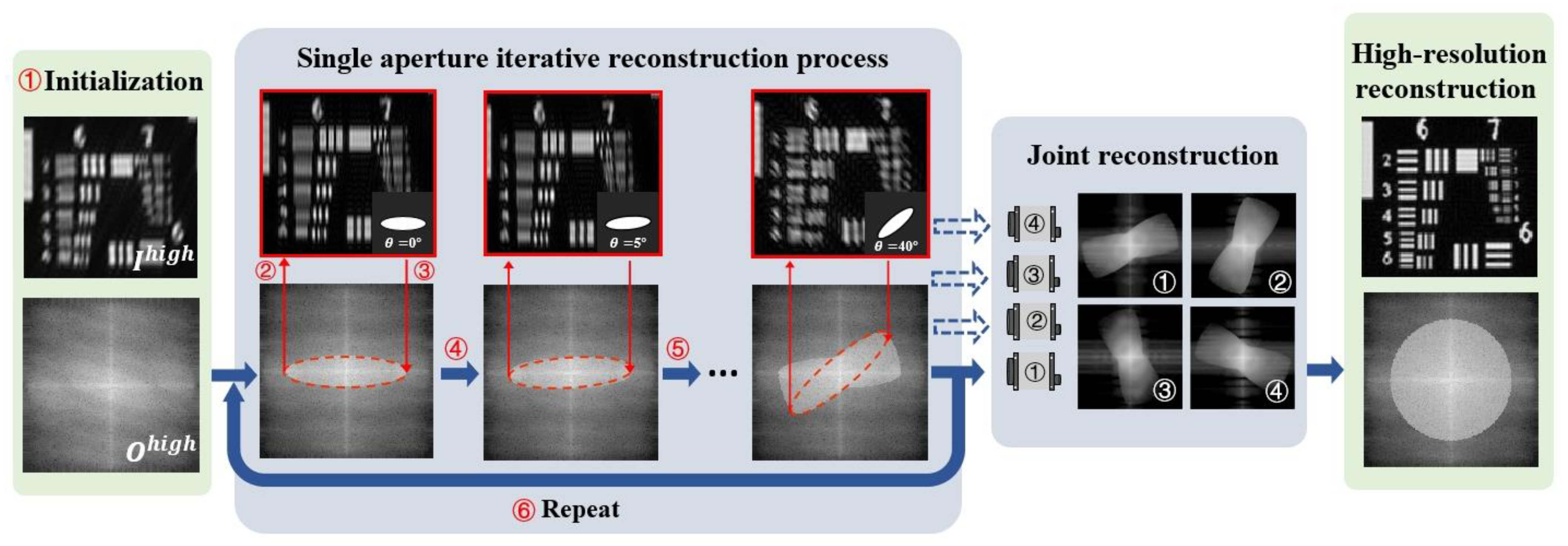
2.2. Pixel Super-Resolution

The smallest resolvable feature on the image plane for an incoherent imaging system can be calculated with the equation 1.22 λ f / D , where λ, f, and D represent the central wavelength, the focal length of the imaging lens, and the aperture diameter, respectively. According to the Nyquist sampling theorem, pixel aliasing can be avoided if the sampling frequency is at least double the signal frequency [31]. Essentially, the sensor can fully capture the low-pass-filtered light field information, as long as the smallest distinguishable feature is at least two pixels or more in size. If the pixel size fails to meet the specified requirements, the light field information will be under-sampled. This can cause pixel aliasing and greatly reduce the quality of the image.
We demonstrated the entire process of pixel under-sampling in optical systems with simulation experiments. The ground truth and spectrum of the low-pass-filtered image obtained with the optical system are shown in Figure 3a,b, respectively. The image captured by using standard pixel sampling is depicted in Figure 3c. Figure 3d displays the image with under-sampling effects due to the larger pixel size.
By utilizing the Fourier ptychography approach, pixel super-resolution is achieved by capturing image sequences with encoded and modulated optical pupil functions, resulting in varying spatial frequency data. Figure 4a displays a schematic illustration of the aperture-coded Fourier ptychographic imaging device, as explained in the section on the image formation model. The operational concept is illustrated in Figure 4b. By employing elliptical apertures with inconsistent long and short axes, we can filter the target’s spectrum and generate an image with varying resolution in the orthogonal directions. By employing mechanical rotation or a spatial light modulation device such as a DMD with digitally coded modulation, we sequentially rotate the aperture up to 180° and collect one low-resolution image at each rotation.
By utilizing the optical transfer function as a constraint, the algorithm simulates the transfer of optical field information between the spatial and frequency domains, allowing for alternate iterations and updates [32]. The algorithm implementation process is detailed as follows:
  • The initial estimated intensity image of the high-resolution target ( I h i g h x , y ) is obtained by using the up-sampling result from averaging the low-resolution images taken with all coded apertures:
    I h i g h x , y = U p s a m p l e i = 1 N I i c , l o w x , y / N
    where N denotes the total number of captured images, I i c , l o w x , y denotes the captured down-sampled low-resolution image, and U p s a m p l e denotes the up-sampling process. Then, the estimated high-resolution spectrum of the target can be expressed as O h i g h u , v = F I h i g h x , y .
  • Generation of low-resolution estimates of light fields: The first step involves performing a Fourier transformation on the high-resolution target, after which the optical system applies a low-pass filter. Here, we define H i u , v as the optical transfer function corresponding to the i-th coded aperture. Then, the intensity information ( o i e , l o w x , y ) is captured by the detector after the Fourier inverse transform:
    o i e , l o w x , y = D o w n s a m p l e F 1 O h i g h u , v H i u , v
    where D o w n s a m p l e   denotes the down-sampling process.
  • Implementation of spatial-domain intensity constraints: The amplitude of the estimated optical field ( o i e , l o w ) is replaced with the actual captured low-resolution intensity image ( I i c , l o w ), and the phase information is kept unchanged to obtain the replaced estimated optical field ( o i u , l o w ).
    o i u , l o w x , y = I i c , l o w x , y o i e , l o w x , y o i e , l o w x , y
  • Updating of the spectrum for high-resolution targets: We up-sample the replaced light field ( o i u , l o w x , y ) and transform it to the frequency domain to update the region selected by the coded aperture: O i u , h i g h x , y = F U p s a m p l e o i u . l o w .
    O h i g h u , v = O h i g h u , v + α M i u , v O i u , l o w u , v O i e , l o w u , v H i u , v + τ
    M i u , v = 1 , H i u , v 0 0 , H i u , v = 0
    where τ is the regularization parameter, α is the adaptive step parameter, and M i u , v is the zero–one mask of the optical transfer function.
  • Repetition of the updating process: Steps 2 to 4 are repeated for all acquired low-resolution images, which is considered completing one iteration.
  • Iteration until convergence: Steps 2 to 5 are repeated until the algorithm converges to complete the reconstruction process of the high-resolution target spectrum. Subsequently, a Fourier inverse transform is applied to it to obtain the high-resolution complex amplitude information of the target. The goal of the iteration step is to minimize the difference between the estimated light field information and the actual low-resolution image acquired.

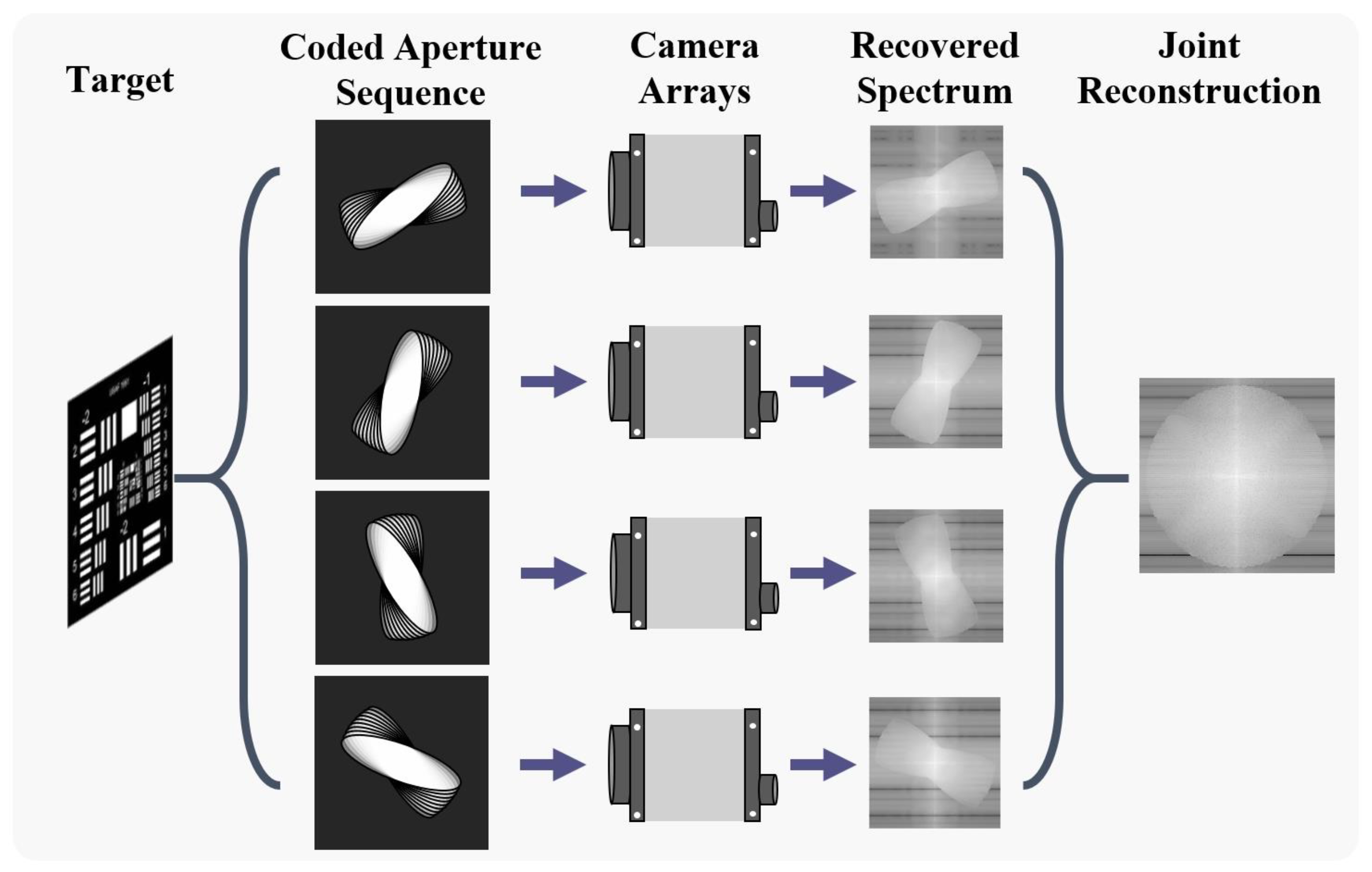
2.3. Joint Reconstruction of Multiple Apertures

The above analysis was shown to be effective in achieving uniform resolution enhancement in under-sampled low-resolution images, as reported below in the experimental section. Advancements in small satellite platforms, such as CubeStar, have enabled us to extend the use of this pixel super-resolution technique from single-aperture to multi-aperture imaging devices (e.g., camera arrays). The workflow is shown in Figure 5.
In the procedure of single-aperture-coded imaging for each subsystem, adjusting the aperture to a rotation angle of 5° requires the capturing of 36 consecutive images (180°/5° = 36). Throughout the process of image acquisition, it is imperative to keep both the system and target stable to avoid recording and amplifying errors during recovery. Relatively speaking, the multi-aperture-coded imaging process does not require additional positional accuracy while extending the image spectrum through fusion. For instance, in the case of the four-aperture camera array, if the total data volume remains constant, each individual sub-aperture only needs to capture nine low-resolution images. Initially, we apply a single-aperture reconstruction algorithm to reconstruct the incomplete spectrum information of the target for each sub-aperture. Then, we utilize multi-scale image fusion to jointly reconstruct information acquired with multiple apertures and obtain the reconstruction outcomes of the sub-apertures. The system acquisition speed can thus be significantly increased, resulting in improved temporal resolution and enhanced robustness.
The multi-scale image fusion technique we use is based on Laplace pyramid decomposition [33,34]. It ensures that the reconstruction results of different sub-apertures are decomposed into different spatial frequency bands and that feature and detail information at different spatial frequencies is fused. The steps are as follows:
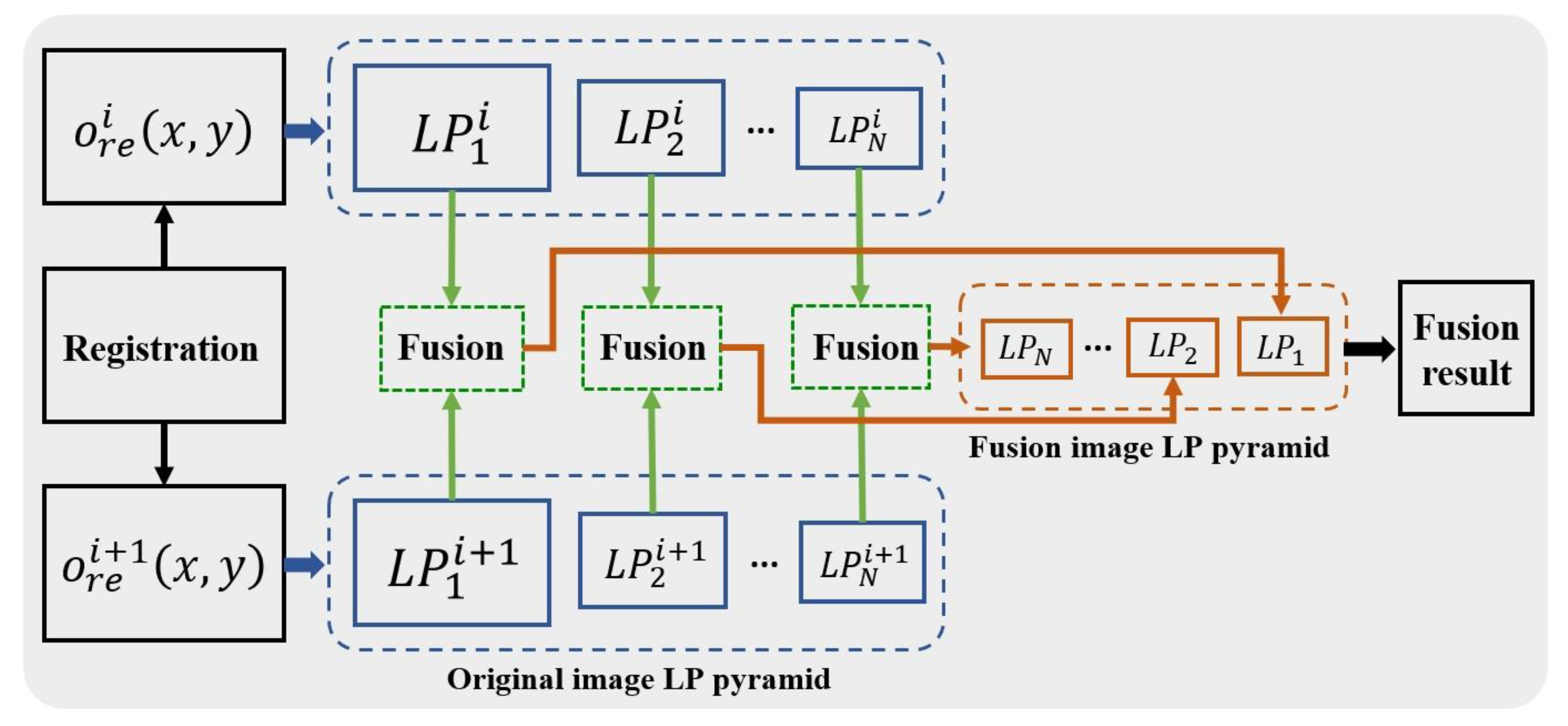
  • Gaussian pyramid decomposition is first performed on the high-resolution results of aligned single-aperture reconstruction:
    G l i x , y = G a u s s i a n P y r a m i d o r e i x , y
    where G l i x , y denotes the l-th layer pyramid decomposition image of the i-th sub-aperture reconstruction result, G a u s s i a n P y r a m i d denotes the Gaussian pyramid decomposition process, and o r e i x , y denotes the high-resolution reconstruction of the i-th sub-aperture.
  • Creation of a Laplace pyramid. We interpolate the Gaussian pyramid to obtain the image G l i x , y , which has the same dimensions as G l 1 i x , y :
    G l i x , y = U p s a m p l e G l i x , y
    L P l i = G l i G l + 1 i , 0 l < N L P N i = G N i , l = N
    where N denotes the highest layer of the Laplace pyramid and L P denotes the Laplace image pyramid.
  • The fusion process is performed layer by layer starting from the top layer of the Laplace image pyramid of the sub-aperture high-resolution reconstruction result. The fused Laplace pyramid is obtained based on the fusion rule of maximum absolute value at high frequencies and average value at low frequencies. Finally, the inverse step of decomposition is applied to the fused pyramid to obtain the fused reconstructed image. The whole multi-scale fusion framework based on Laplace pyramid decomposition is shown in Figure 6.

3. Results

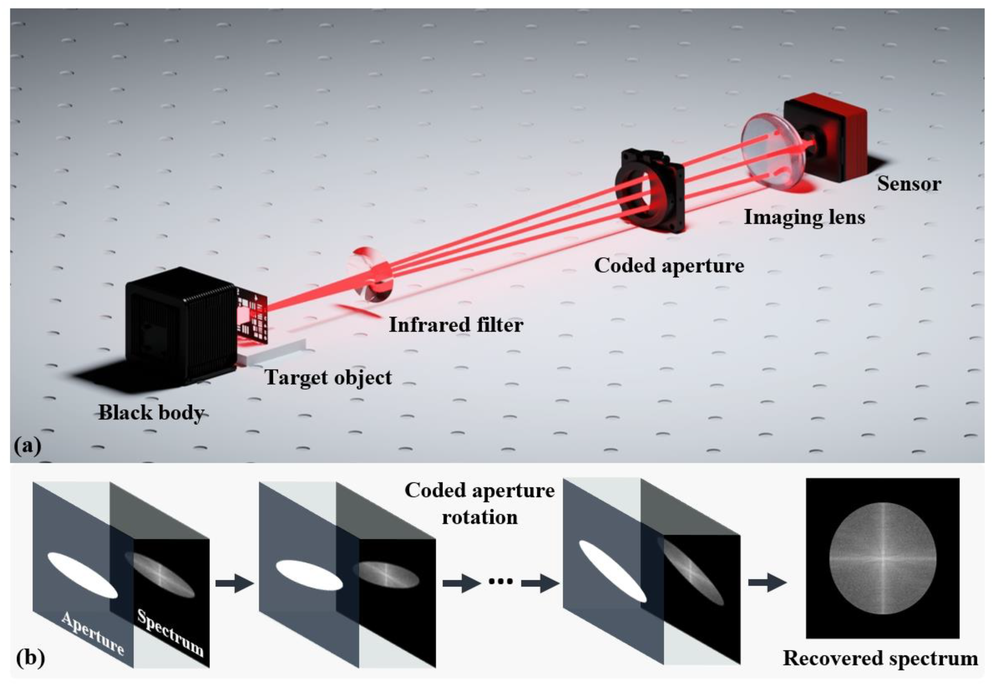
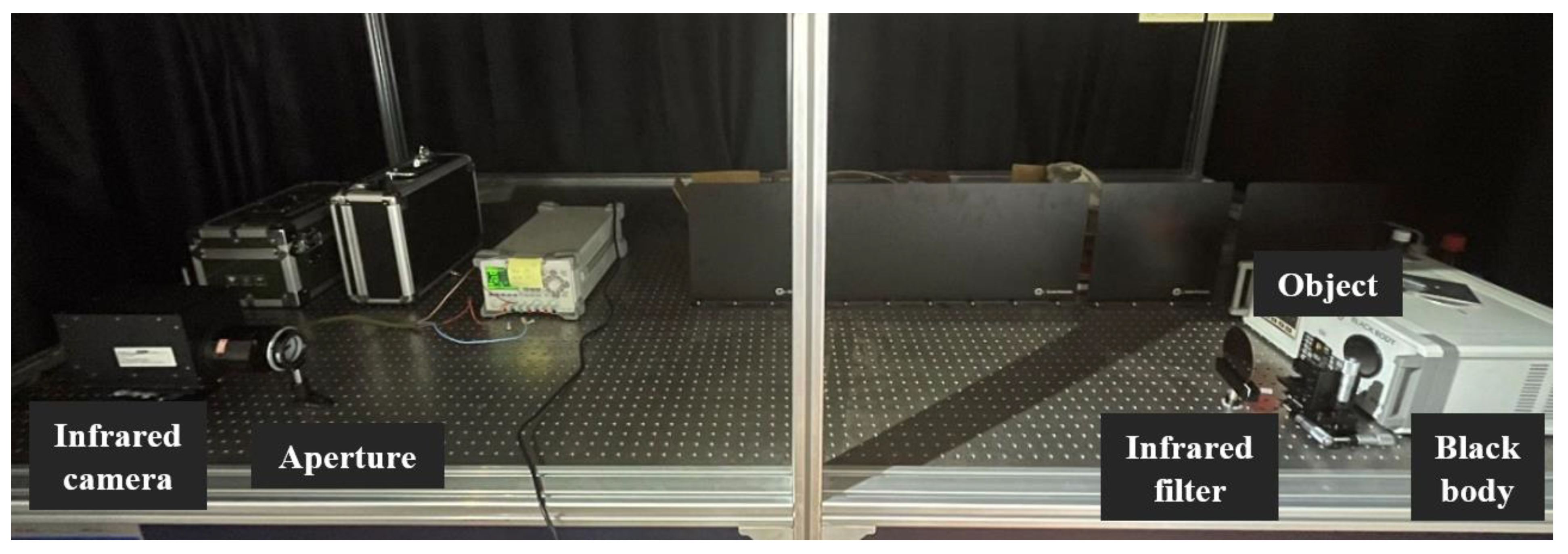
3.1. Experimental Setup

As shown in Figure 7, we built an infrared imaging system and simulated the imaging effect of the camera array by controlling the movement of the imaging target. We used a blackbody as the illumination device, which had a 60 mm diameter aperture and was able to provide a temperature adjustment range of 0–500 °C, a stability accuracy of ±1 °C, a radiation coefficient of 0.97 ± 0.01, and a radiation wavelength of 2–14 µm. The imaging system consisted of a detector (SOFRAFDIR; France; 320 pixels × 256 pixels, 30 µm pixel pitch, medium infrared band) and an infrared imaging lens (f = 100 mm, F/#2, film coating of 3–5 µm). In order to enhance the temporal coherence of the system, we set up a narrowband filter with a center wavelength of 4020 nm and a bandwidth of 150 nm. The negative USAF1951 resolution target placed at the blackbody exit was used as the experimental sample.
The optical pupil was equipped with an elliptical aperture in front of the lens, which was then rotated mechanically to achieve coded modulation. The elliptical aperture had a long axis of 31 mm and a short axis of 8 mm. By designing our setup in this manner, we ensured that the spatial frequency for the shorter axis was sampled normally, while the spatial frequency for the longer axis of the elliptical aperture was under-sampled. It should be noted that the physical rotation utilized in our experimental configuration is simply a representation and could be interchanged with a digital micromirror array or a spatial light modulator for digital manipulation.
We sequentially validated the effectiveness of the single-aperture reconstruction and multi-aperture joint reconstruction algorithms. By rotating the elliptical aperture by 5° for each image, we were able to acquire 36 low-resolution images with different frequency information along the orthogonal directions during the single-camera imaging process. Following this, we exchanged the elliptical aperture with an equivalent synthetic aperture for imaging and obtained a full-aperture high-resolution image for comparison. We simulated the imaging result of a four-camera array by physically moving the camera through a mechanical translation stage for the multi-aperture joint imaging technique. With multi-aperture-coded joint modulation, only nine low-resolution images needed to be acquired for each sub-aperture.

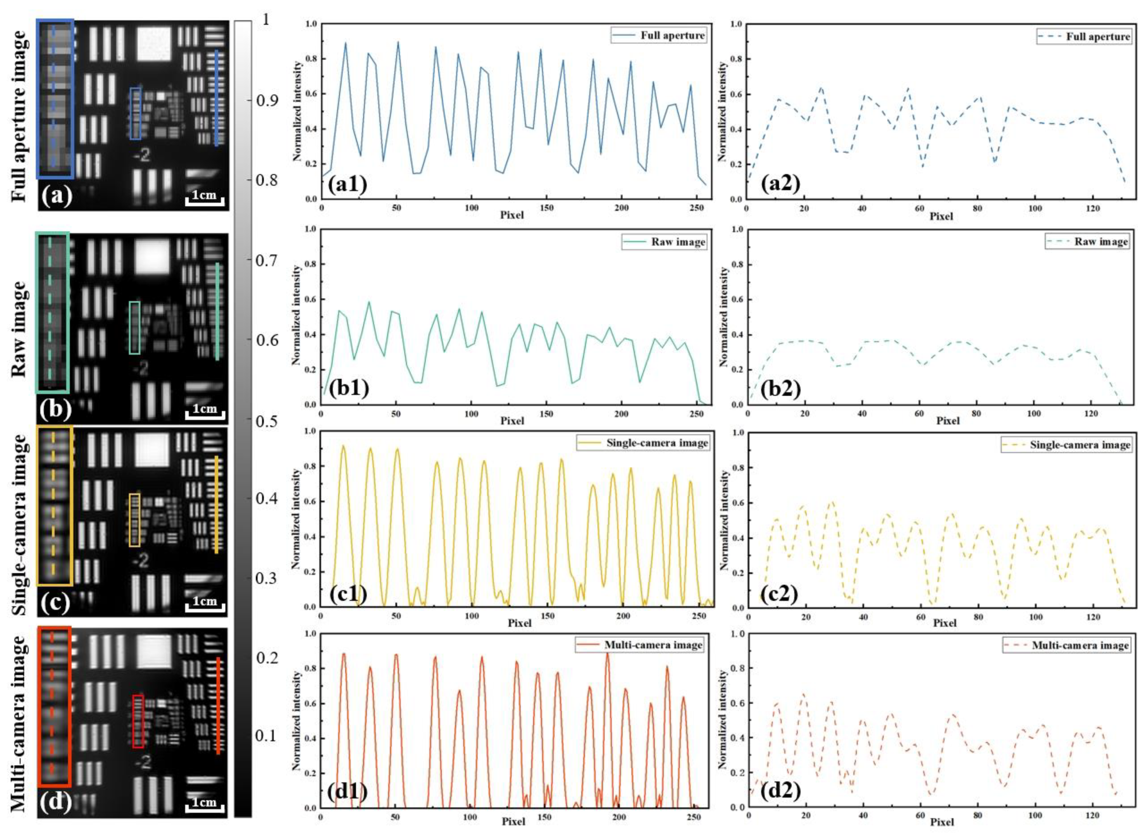
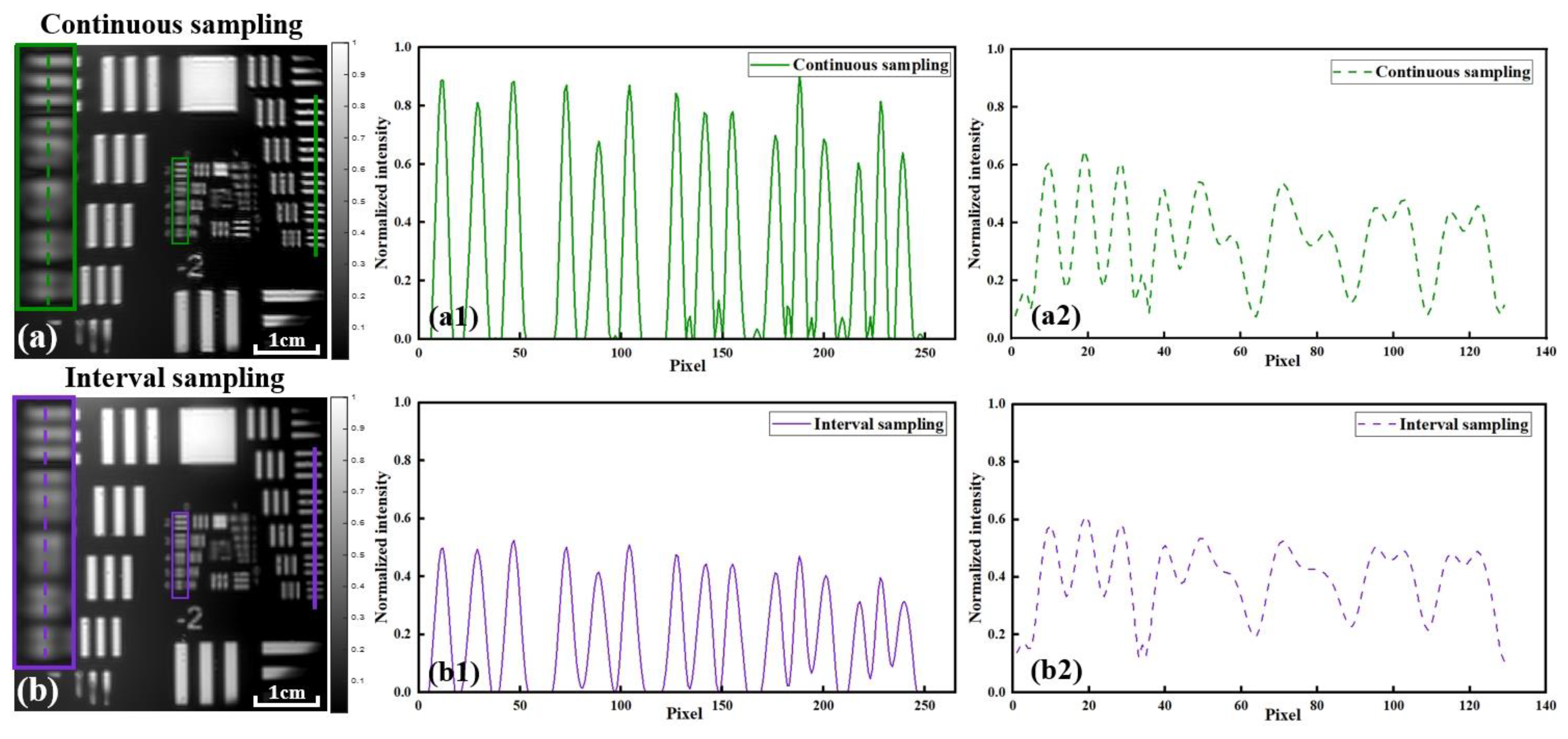
3.2. Spatial Resolution Results

The full-aperture image, raw image, and recovered high-resolution images obtained by using a single camera and multiple cameras are shown in Figure 8a–d, respectively. It should be noted that the image depicted in Figure 8b is merely a low-resolution image in a particular direction. Its corresponding coded aperture is an elliptical aperture with a long horizontal axis and a short vertical axis (that is, the mask rotation angle is 0°). The spatial resolution disparity between the images in the horizontal and vertical directions was the highest, as depicted in Figure 8b. As previously stated, the resolution in the horizontal direction was limited by the size of the short elliptical axis. Although the long axis had a higher frequency transfer capacity, the detector pixel size constraint resulted in the vertical resolution being inferior to the horizontal resolution, which only performed better in terms of contrast.
By comparing Figure 8a,b, it can be easily found that the visual performance of the line pair in the full-aperture image was better. However, by further comparing the normalized intensity profiles of the line pairs of both in Figure 8a1–a2,b1–b2, it can be seen that the spatial resolutions of full-aperture imaging and elliptical-aperture modulation imaging were at the same level. Group 1 element 6 (561.24 µm periodicity, corresponding to 63.98 µm imaging resolution, which is twice the pixel size) could be resolved in both cases. Significantly, neither was able to resolve sharper line pairs, which is the result of pixel aliasing, preventing higher spatial frequencies from being recorded by the detector.
As shown in Figure 8c, the recovery result obtained by using a single camera was able to resolve group 0 element 5 (314.98 µm periodicity, corresponding to 35.90 µm imaging resolution). By observing the pairs of lines oriented perpendicularly to each other, we can see that our algorithm has the ability to achieve consistent resolution recovery across different orientations. Compared with the raw image, the recovery result achieved a 1.78-fold resolution improvement and an overall better line-pair contrast; moreover, it also achieved the same resolution improvement and better contrast for high-frequency pairs compared with the full-aperture image, which can be easily inferred from Figure 8a2–c2.
In addition, the result obtained by using multiple cameras could resolve group 0 element 4 (353.55 µm periodicity, corresponding to 40.30 µm imaging resolution) in Figure 8d. Compared with the raw and full-aperture images, we can see that the results still provided a consistent resolution improvement in the orthogonal direction, a 1.59-fold improvement, and better performance in terms of line-pair contrast. It is worth noting that this recovery method is based on the quadrupling of the temporal resolution of the entire acquisition setup (i.e., for each camera, the number of data acquired becomes one-fourth of the original total).
Further, we explored the effect of different multi-camera co-sampling methods on the recovery results. The multi-camera results in Figure 8d were obtained by using a continuous-sampling method, i.e., each camera captured a low-resolution image under continuous aperture rotation, as shown in Figure 9a. For the joint multi-camera reconstruction interval-sampling experiment, the sampling method is shown in Figure 9b.
It can be easily seen that the recovery results obtained with interval sampling were able to resolve group 0 element 3. From the results in Figure 10, it can be found that the interval-sampling method was able to achieve similar resolution results and better-quality recovered stripes (the artifacts inside the stripes were obviously reduced) compared with the continuous-sampling method. However, the performance was not as satisfactory as that of the latter in terms of the limit of the resolution ability and the contrast of the line pairs. From the two spectral sampling methods in Figure 10, it can be seen that the image set acquired by using a single camera in the continuous-sampling method showed lower coverage of the complete spectrum but that the spectral overlap between adjacent images was higher; on the other hand, the image set acquired by using a single camera with the interval-sampling method achieved higher spectral coverage, but the spectral overlap between adjacent images was lower. Therefore, the continuous-sampling method achieved better limiting resolution and line-pair contrast performance, while the interval-sampling method provided better stripe quality.

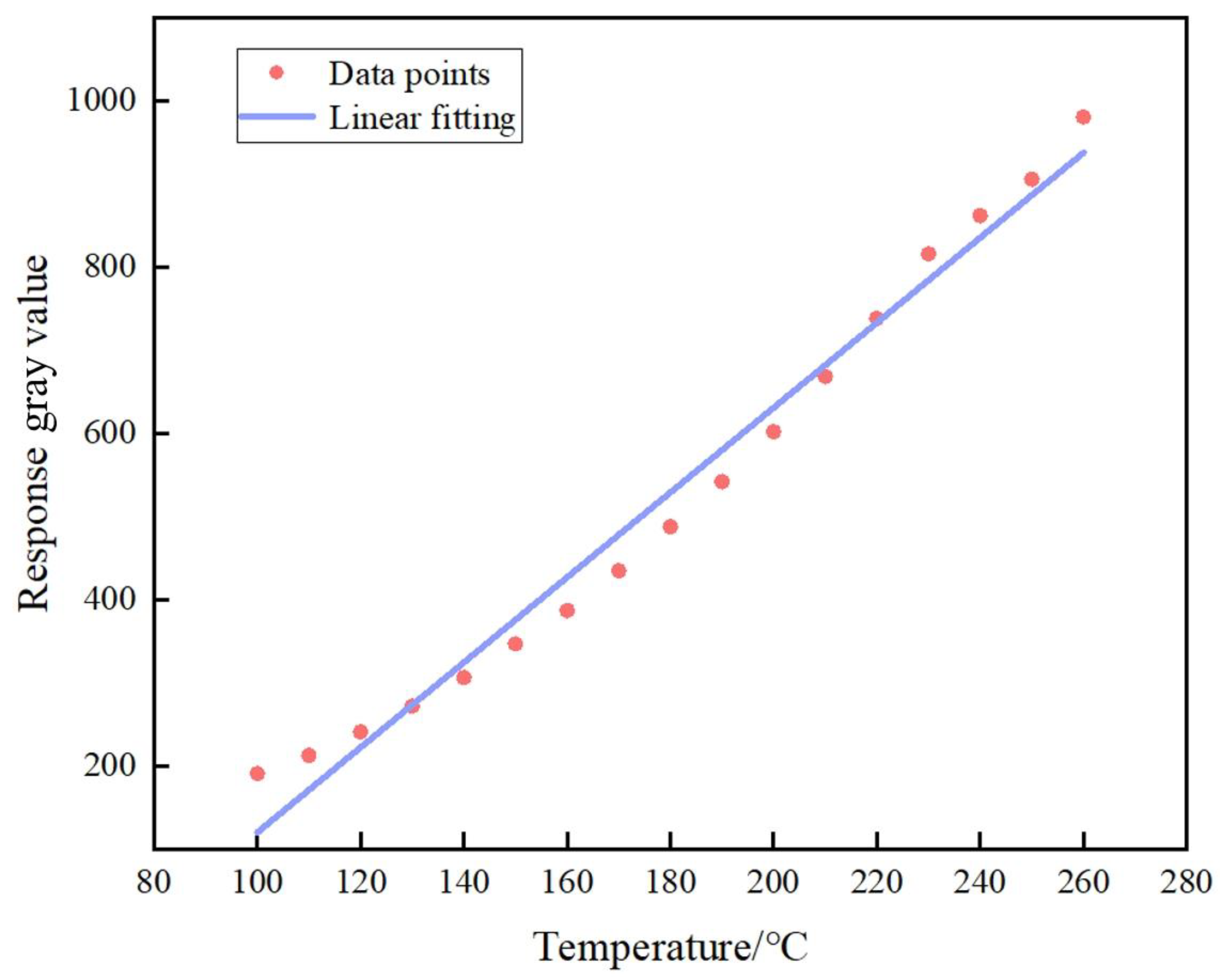
3.3. Temperature Results

In addition to spatial resolution, temperature accuracy is also an important parameter for infrared-band planetary detection, which helps us explore the mysteries of the universe [35]. Therefore, we verified the temperature accuracy of the proposed method by collecting 17 data points for temperature calibration and fitted the calibration curve of the working range, as shown in Figure 11. In our experiments, the temperature of the blackbody was set to 200 °C, and based on the above-mentioned temperature calibration curve, the corresponding temperature for the captured image was calculated to be 195.54 °C (error of 2.23%).

3.4. Discussion on Method Robustness

To prove the robustness of the proposed method, we conducted a more detailed investigation into its effectiveness, and the results are as follows:
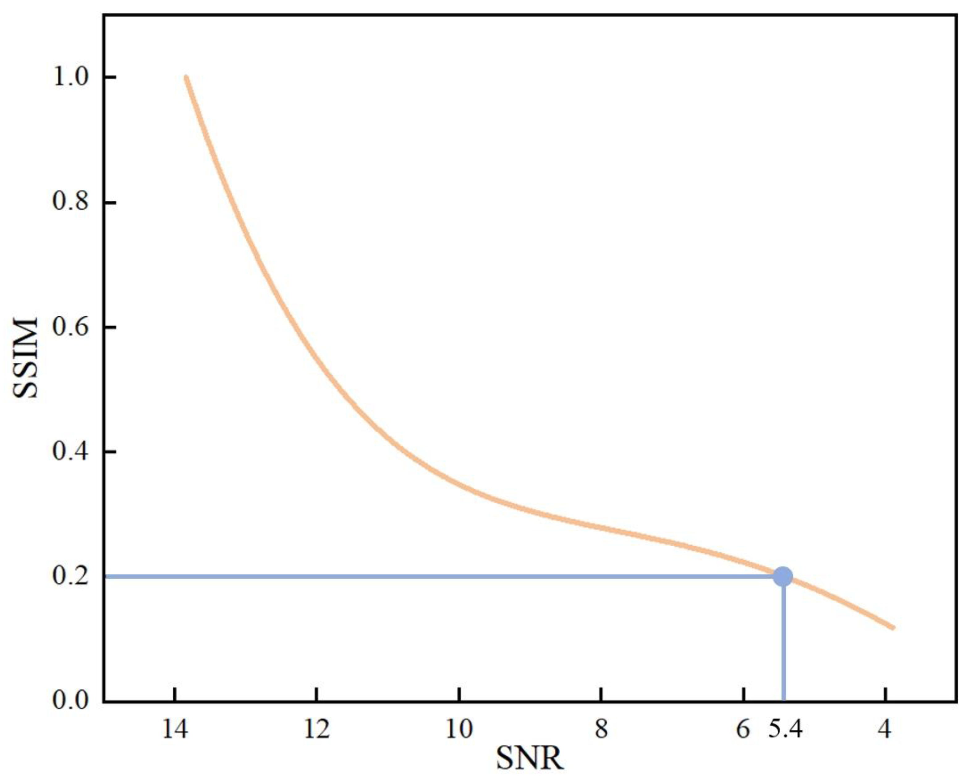
  • SNR: We carried out simulation experiments on low-resolution images under different noise conditions and obtained the corresponding reconstruction results. Taking the noiseless condition as a reference, the reconstruction results were evaluated in terms of the structural similarity index (SSIM) for image quality, as shown in Figure 12. When the SNR of the image was close to 5.4, the structural similarity of the reconstruction result decreased to below 0.2, and the reconstruction quality was unacceptable. It can be seen that the proposed method has certain requirements relative to the SNR of the captured images. Therefore, our subsequent work will focus on how to further improve the SNR of the infrared system.
  • Elliptical-aperture scanning speed: The elliptical rotation speed needs to be selected based on both image SNR and acquisition efficiency. Indeed, both slow rotation, to ensure a sufficient SNR for a single image, and fast speed, to improve the acquisition efficiency of the entire system, are required.
  • Light source: In the experiment, we also attempted to use heated metal plates as infrared targets. Due to the highest heating temperature of the metal plate being 130 °C, the SNR of the collected images was low, which had a certain impact on the reconstruction results. The reason for using this blackbody as a light source is that it provides stable infrared radiation at high temperatures and high SNRs.
  • Vibration and camera stability: In the high-resolution imaging scheme based on conventional synthetic apertures, the sub-wavelength scale of phase accuracy requires the sub-aperture to be highly stable. Different from those of conventional methods, the requirements of the proposed method in terms of camera stability are comparable to those of conventional single-aperture loads, i.e., the platform is required to be free from large vibrations as well as other instabilities during the exposure time of a single imaging session.

4. Conclusions

In this paper, we present a computational imaging method (multi-aperture joint-encoding Fourier ptychography (JEFP)) as a practical means to achieve super-resolution infrared imaging for distributed platforms in planetary exploration missions. By merging reconstructed images from several sub-apertures, this approach enables distributed systems to achieve high temporal resolution. The proposed method solves the pixel aliasing problem by means of systematic coding and algorithmic decoding. Further, sensors with larger pixel sizes can be used to obtain superior SNRs and reduce the processing and manufacturing costs of the system. In addition, the proposed method does not require the system to be mechanically scanned in space, thus offering the possibility for distributed systems to recover the amplitude and phase of the light field in a simpler and faster way. It should be noted that the method’s temporal coherence requirement decreases the SNR of the captured images. The JEFP scheme proposed in this paper extends the application scope of Fourier ptychographic imaging, especially for distributed synthetic-aperture imaging systems, which not only improves the acquisition efficiency of the system and reduces the control accuracy requirements of the distributed system, but also greatly reduces the volume and weight of the system and the manufacturing costs. For planetary exploration missions that require greater adaptability and design lifetime, our distributed scheme can also provide less strict deployment conditions and higher risk tolerance for a single camera.

Author Contributions

Conceptualization, M.X. and X.S.; methodology, T.W.; software, T.W.; validation, F.L., X.D. and J.L.; formal analysis, T.W.; investigation, S.W. and G.L.; writing—original draft preparation, T.W.; writing—review and editing, M.X.; visualization, T.W.; supervision, F.L.; funding acquisition, X.S. All authors have read and agreed to the published version of the manuscript.

Funding

This research was funded by the National Natural Science Foundation of China, grant numbers 62205259, 62075175, 61975254, 62105254; the Open Research Fund of CAS Key Laboratory of Space Precision Measurement Technology, grant number B022420004; and the National Key Laboratory of Infrared Detection Technologies grant number IRDT-23-06.

Data Availability Statement

The data presented in this study are available upon reasonable request from the corresponding author.

Conflicts of Interest

The authors declare no conflicts of interest.

References

  1. Zhu, L.; Suomalainen, J.; Liu, J.; Hyyppä, J.; Kaartinen, H.; Haggren, H. A Review: Remote Sensing Sensors. In Multi-Purposeful Application of Geospatial Data; Rustamov, R.B., Hasanova, S., Zeynalova, M.H., Eds.; InTech: Houston, TX, USA, 2018; ISBN 978-1-78923-108-3. [Google Scholar]
  2. Lu, D.; Liu, Z. Hyperlenses and Metalenses for Far-Field Super-Resolution Imaging. Nat Commun 2012, 3, 1205. [Google Scholar] [CrossRef] [PubMed]
  3. Tippie, A.E.; Kumar, A.; Fienup, J.R. High-Resolution Synthetic-Aperture Digital Holography with Digital Phase and Pupil Correction. Opt. Express 2011, 19, 12027–12038. [Google Scholar] [CrossRef] [PubMed]
  4. Rogalski, A.; Martyniuk, P.; Kopytko, M. Challenges of Small-Pixel Infrared Detectors: A Review. Rep. Prog. Phys. 2016, 79, 046501. [Google Scholar] [CrossRef] [PubMed]
  5. Barnard, K.J. High-Resolution Image Reconstruction from a Sequence of Rotated and Translated Frames and Its Application to an Infrared Imaging System. Opt. Eng 1998, 37, 247. [Google Scholar] [CrossRef]
  6. Harris, J.L. Diffraction and Resolving Power. J. Opt. Soc. Am. 1964, 54, 931. [Google Scholar] [CrossRef]
  7. Dong, C.; Loy, C.C.; He, K.; Tang, X. Image Super-Resolution Using Deep Convolutional Networks. IEEE Trans. Pattern Anal. Mach. Intell. 2016, 38, 295–307. [Google Scholar] [CrossRef] [PubMed]
  8. Dong, C.; Loy, C.C.; Tang, X. Accelerating the Super-Resolution Convolutional Neural Network. In Computer Vision—ECCV 2016; Leibe, B., Matas, J., Sebe, N., Welling, M., Eds.; Lecture Notes in Computer Science; Springer International Publishing: Cham, Swizerland, 2016; Volume 9906, pp. 391–407. ISBN 978-3-319-46474-9. [Google Scholar]
  9. Baker, S.; Kanade, T. Limits on Super-Resolution and How to Break Them. In Proceedings of the IEEE Conference on Computer Vision and Pattern Recognition, Hilton Head, SC, USA, 13–15 June 2000. [Google Scholar]
  10. Lin, Z.; Shum, H.Y. Fundamental Limits of Reconstruction-Based Superresolution Algorithms under Local Translation. IEEE Trans. Pattern Anal. Mach. Intell. 2004, 26, 83–97. [Google Scholar] [CrossRef]
  11. Nguyen, N.; Milanfar, P. A Wavelet-Based Interpolation-Restoration Method for Superresolution. Circuits Syst. Signal Process. 2000, 19, 321–338. [Google Scholar] [CrossRef]
  12. Irani, M.; Peleg, S. Improving Resolution by Image Registration. CVGIP Graph. Models Image Process. 1991, 53, 231–239. [Google Scholar] [CrossRef]
  13. Sohail, M. Geometric Superresolution Using an Optical Rectangular Mask. Opt. Eng 2012, 51, 013203. [Google Scholar] [CrossRef]
  14. Sohail, M.; Mudassar, A.A. Geometric Superresolution by Using an Optical Mask. Appl. Opt. 2010, 49, 3000. [Google Scholar] [CrossRef]
  15. Haq, I.U.; Mudassar, A.A. Geometric Super-Resolution Using Negative Rect Mask. Optik 2018, 168, 323–341. [Google Scholar] [CrossRef]
  16. Wang, B.; Zou, Y.; Zuo, C.; Sun, J.; Hu, Y. Pixel Super Resolution Imaging Method Based on Coded Aperture Modulation; SPIE: Bellingham, WA, USA, 2021; Volume 11761, p. 1176111. [Google Scholar]
  17. Tao, Y.; Muller, J.-P. A Novel Method for Surface Exploration: Super-Resolution Restoration of Mars Repeat-Pass Orbital Imagery. Planet. Space Sci. 2016, 121, 103–114. [Google Scholar] [CrossRef]
  18. La Grassa, R.; Cremonese, G.; Gallo, I.; Re, C.; Martellato, E. YOLOLens: A Deep Learning Model Based on Super-Resolution to Enhance the Crater Detection of the Planetary Surfaces. Remote Sens. 2023, 15, 1171. [Google Scholar] [CrossRef]
  19. Wang, C.; Zhang, Y.; Zhang, Y.; Tian, R.; Ding, M. Mars Image Super-Resolution Based on Generative Adversarial Network. IEEE Access 2021, 9, 108889–108898. [Google Scholar] [CrossRef]
  20. Wu, Y.; Cheng, W.; Wen, C. A Method to Determine the Parameters of Infrared Camera in the Electron Optic Tracking System of UAV. In Proceedings of the AOPC 2020: Optical Sensing and Imaging Technology, Beijing, China, 30 November–2 December 2020; SPIE: Bellingham, WA, USA, 2020; Volume 11567, pp. 139–144. [Google Scholar]
  21. Xiang, M.; Pan, A.; Zhao, Y.; Fan, X.; Zhao, H.; Li, C.; Yao, B. Coherent Synthetic Aperture Imaging for Visible Remote Sensing via Reflective Fourier Ptychography. Opt. Lett. 2021, 46, 29. [Google Scholar] [CrossRef] [PubMed]
  22. Miyamura, N.; Suzumoto, R.; Ikari, S.; Nakasuka, S. Conceptual Optical Design of a Synthetic Aperture Telescope by Small Satellite Formation Flying for GEO Remote Sensing. Aerosp. Technol. Jpn. 2020, 18, 101–107. [Google Scholar] [CrossRef]
  23. Fienup, J.P. Direct-Detection Synthetic-Aperture Coherent Imaging by Phase Retrieval. Opt. Eng 2017, 56, 113111. [Google Scholar] [CrossRef]
  24. Wu, Y.; Hui, M.; Li, W.; Liu, M.; Dong, L.; Kong, L.; Zhao, Y. MTF Improvement for Optical Synthetic Aperture System via Mid-Frequency Compensation. Opt. Express 2021, 29, 10249. [Google Scholar] [CrossRef]
  25. Underwood, C.; Pellegrino, S.; Lappas, V.; Bridges, C.; Taylor, B.; Chhaniyara, S.; Theodorou, T.; Shaw, P.; Arya, M.; Breckinridge, J.; et al. Autonomous Assembly of a Reconfiguarble Space Telescope (AAReST)—A CubeSat/Microsatellite Based Technology Demonstrator. In Proceedings of the 27th Annual AIAA/USU Conference on Small Satellites, Logan, UT, USA, 10–15 August 2013. [Google Scholar]
  26. Zhang, Q.; Liu, Y.; Blum, R.S.; Han, J.; Tao, D. Sparse Representation Based Multi-Sensor Image Fusion: A Review. Inf. Fusion 2017, 40, 57–75. [Google Scholar] [CrossRef]
  27. Zhou, Z.; Li, S.; Wang, B. Multi-Scale Weighted Gradient-Based Fusion for Multi-Focus Images. Inf. Fusion 2014, 20, 60–72. [Google Scholar] [CrossRef]
  28. Blum, R.S.; Liu, Z. Multi-Sensor Image Fusion and Its Applications; CRC Press: Boca Raton, FL, USA, 2018. [Google Scholar]
  29. Zheng, G.; Horstmeyer, R.; Yang, C. Wide-Field, High-Resolution Fourier Ptychographic Microscopy. Nat. Photonics 2013, 7, 739–745. [Google Scholar] [CrossRef]
  30. Dong, S.; Bian, Z.; Shiradkar, R.; Zheng, G. Sparsely Sampled Fourier Ptychography. Opt. Express 2014, 22, 5455–5464. [Google Scholar] [CrossRef] [PubMed]
  31. Sun, J.; Chen, Q.; Zhang, Y. Sampling Criteria for Fourier Ptychographic Microscopy in Object Space and Frequency Space. Opt. Express 2016, 24, 15765–15781. [Google Scholar] [CrossRef] [PubMed]
  32. Zheng, G.; Shen, C.; Jiang, S.; Song, P.; Yang, C. Concept, Implementations and Applications of Fourier Ptychography. Nat Rev Phys 2021, 3, 207–223. [Google Scholar] [CrossRef]
  33. Adelson, E.H.; Anderson, C.H.; Bergen, J.R.; Burt, P.J.; Ogden, J.M. Pyramid Methods in Image Processing. RCA Eng. 1984, 29, 33–41. [Google Scholar]
  34. Burt, P.J.; Adelson, E.H. The Laplacian Pyramid as a Compact Image Code. In Readings in Computer Vision; Elsevier: Amsterdam, The Netherlands, 1987. [Google Scholar]
  35. Pierrehumbert, R.T. Infrared Radiation and Planetary Temperature. Phys. Today 2011, 64, 33–38. [Google Scholar] [CrossRef]
Figure 1. Schematic of distributed detection system for implementation of JEFP.
Remotesensing 16 01017 g001
Figure 2. Workflow of multi-aperture joint-encoding Fourier ptychographic imaging method (JEFP).
Remotesensing 16 01017 g002
Figure 3. Simulation of the pixel aliasing problem. (a) The ground truth. (b) The spectrum of the low-pass-filtered image obtained with the optical system. (c) The low-resolution image obtained with systematic low-pass filtering and standard pixel sampling. (d) The low-resolution image with under-sampling effects due to larger pixel size.
Remotesensing 16 01017 g003
Figure 4. Workflow for aperture-coded Fourier ptychographic imaging. (a) Schematic of aperture-coded Fourier ptychographic imaging device. (b) Coded aperture-based rotary sampling.
Remotesensing 16 01017 g004
Figure 5. Workflow for joint reconstruction with multi-aperture coding.
Remotesensing 16 01017 g005
Figure 6. Multi-scale fusion framework.
Remotesensing 16 01017 g006
Figure 7. Experimental setup for aperture-coded Fourier ptychographic imaging.
Remotesensing 16 01017 g007
Figure 8. Experimental results and normalized intensity distribution. (a) Full-aperture image. (b) Raw image. (c) Image recovered by using a single camera. (d) Image recovered by using multiple cameras. (a1d1) Normalized intensity distribution of the solid line in (ad). (a2d2) Normalized intensity distribution of the dotted lines in (ad).
Remotesensing 16 01017 g008
Figure 9. Coding sampling order for joint reconstruction. (a) Continuous sampling. (b) Interval sampling.
Remotesensing 16 01017 g009
Figure 10. Comparison of experimental results for different sampling methods. (a) Image recovered with continuous sampling. (b) Image recovered with interval sampling. (a1,b1) Normalized intensity distribution of the solid lines in (a,b). (a2,b2) Normalized intensity distribution of the dotted lines in (a,b).
Remotesensing 16 01017 g010
Figure 11. Temperature calibration curve.
Remotesensing 16 01017 g011
Figure 12. Reconstructed image quality at different SNRs.
Remotesensing 16 01017 g012
Disclaimer/Publisher’s Note: The statements, opinions and data contained in all publications are solely those of the individual author(s) and contributor(s) and not of MDPI and/or the editor(s). MDPI and/or the editor(s) disclaim responsibility for any injury to people or property resulting from any ideas, methods, instructions or products referred to in the content.

