Article

Design and Testing of an Adaptive In-phase Magnetometer (AIMAG), the Equatorial-Electrojet-Detecting Fluxgate Magnetometer, for the CAS500-3 Satellite

1
Department of Astronomy and Space Science, Chungbuk National University, Cheongju 28644, Republic of Korea
2
Satellite Technology Research Center, Korea Advanced Institute of Science and Technology, Daejeon 34051, Republic of Korea
*
Author to whom correspondence should be addressed.
Remote Sens. 2023, 15(19), 4829; https://doi.org/10.3390/rs15194829
Submission received: 30 August 2023 / Revised: 27 September 2023 / Accepted: 3 October 2023 / Published: 5 October 2023
(This article belongs to the Special Issue Satellite Observations of the Global Ionosphere and Plasma Dynamics)

Abstract

:
Ionospheric Anomaly Monitoring by Magnetometer And Plasma-probe (IAMMAP) is a suite of scientific instruments used in the Compact Advanced Satellite 500-3 (CAS 500-3), which is planned to be launched by the KSLV (Korean Space Launch Vehicle) in 2025. The main scientific objective of IAMMAP is to understand the complicated correlation between the equatorial electrojet (EEJ) and the equatorial ionization anomaly (EIA), both of which play important roles in the dynamics of ionospheric plasma in the dayside equator region. The magnetic field generated by the EEJ is tiny (~several nT) compared to the background geomagnetic field (~30,000 nT); thus, a high-resolution magnetometer with a wide dynamic range is required to investigate its correlation with the EIA. To achieve this required resolution, IAMMAP includes a set of improved fluxgate magnetometers named the AIMAG (Adaptive In-phase MAGnetometer), which was developed by adopting new technologies. Here, we report the analysis results of the manufactured AIMAG performance based on trade-off studies for optimizing the circuit and sensor configurations. The results support that the AIMAG sensor and electronic circuits with new concepts and technologies will lead to successful observations of EEJ signatures in the ionosphere.

1. Introduction

In the E-region of the Earth’s ionosphere, there exists a current flowing in the zonal (west-east) direction in the vicinity of the geomagnetic equator, which is called the equatorial electrojet (EEJ) [1]. High-precision fluxgate magnetometers, which have been widely employed in various space missions [2,3,4], are required to identify the tiny magnetic signatures of the EEJ and its possible relation to the equatorial ionization anomaly (EIA) [5].
Both the EEJ and the EIA are thought to be caused by the electric field developed by charge separation between the dawn and dusk sides of the ionosphere as a result of collisions between plasma and neutral wind, although the altitudes of the two phenomena are different. Figure 1 demonstrates the EEJ flowing eastward along the equatorial E-region of the ionosphere (blue arrow). This occurs due to the large electric field that develops between the dawn and dusk sides owing to the conducting nature of the ionospheric plasma. The current is principally the Pederson current, and the Hall current is known to strengthen the eastward current [6]. Sq (Solar quiet) currents also exist in the midlatitude region, as shown in Figure 1. However, the magnetic field generated by Sq currents is weaker than that of the EEJ and has been described in a larger region in general [6].
The EIA is generally characterized by a trough of Ne (electron density) along the geomagnetic equator, which is sandwiched by crests of increased Ne in both hemispheres. This feature was first reported in [7]. Appleton [5] later identified the EIA feature, and Moffett and Hanson [8] explained that the formation of the EIA is a consequence of the zonal electric field and its interaction with the geomagnetic field, which occurs along the horizontal direction in the equatorial region, resulting in uplift of the ionospheric plasma, especially in the F-region ionosphere. The underlying mechanism is also known as the fountain effect.
The EEJ and EIA are two representative ionospheric phenomena occurring across the equatorial and mid-latitude regions on the dayside. The two phenomena have been thought to be related to each other. To study the intercorrelation between the EEJ and EIA, the Ionospheric Anomaly Monitoring by Magnetometer And Plasma-probe (hereafter, IAMMAP) was proposed and selected as a scientific instrument for use on the Compact Advanced Satellite 500-3 (CAS 500-3), which is planned to be launched by the KSLV (Korean Space Launch Vehicle) in 2025. The IAMMAP includes a Langmuir probe and an impedance probe, the design and test results of which were reported in [9]. Here, we report on a set of temperature-tolerant high-precision fluxgate magnetometers, named AIMAG (Adaptive In-phase MAGnetometer), which is employed as a part of the IAMMAP instrument suite to study the complicated current system in the ionosphere and magnetosphere, especially in relation to the EEJ.
Fluxgate magnetometers are an important tool for geophysics and space physics research, providing high-precision quasi-DC vector magnetic field data generated from the Earth’s dynamo and currents in the magnetosphere, the ionosphere, and interplanetary space [2,3,4]. The first invention of a fluxgate magnetometer was presented in [10] in 1936, which was improved later in 1962 and 1968 in [11,12]. The first satellite that carried a fluxgate magnetometer was Sputnik III, launched in 1958 [13]. Since then, there have been rapid advances in satellite magnetometers, such as that onboard the MAGSAT satellite launched in 1978 [14] by employing a 6 m boom, a transconductance amplifier, etc. The sensitive dependence of the fluxgate performance on temperature has been a major issue. To overcome this issue, materials that are insensitive to temperature changes are preferentially adopted, the circuitry is made less sensitive to temperature, and experimental lock-up tables are created [15,16,17]. The main distinguishing feature of AIMAG is that it adaptively adjusts the temperature-dependent phase shift effect of the pick-up signal to the in-phase state, contributing to noise reduction.
In the remaining sections, we report on the AIMAG instrument design details (Section 2 and Section 3) and analyze the results of its performance (Section 4). Finally, we summarize the main results and future plans for further improvements to the mission implementation (Section 5).

2. Derivation of Science Requirements for AIMAG

To obtain the required performance of the AIMAG for the study of the EEJ and the EIA, we made use of the model prediction of the EEJ [18] and the most recent magnetic field measurements of the SWARM satellite [19]. The fluxgate magnetometers of the AIMAG were designed to meet the derived requirements, and accordingly, a prototype and a qualification model were developed. There have been attempts to establish a model for estimating the intensity of the EEJ as a function of time and space based on satellite observations. An empirical model was based on POGO satellite data, providing measurements of the mean peak current density, mean total eastward current, mean latitudinal extent, etc., but it did not offer longitudinal or seasonal profiles of the EEJ. Later, the equatorial electrojet climatological model (EEJM-2.0), an empirical model based on data from over 95,000 dip equator crossings from 1999–2006 by Oersted, CHAMP and SAC-C, was published. The variables of the model are longitude, local time, season and solar flux, and the outputs are current density and conductivity values. This information can be used to determine the daily variability of the electrojet [18].
Figure 2 shows an example of the EEJ intensity generated by the EEJM-2.0 empirical model. The model results are just averaged values obtained by a limited number of satellites; thus, they do not include the effect of solar activity, geomagnetic disturbance or lunar phase. Nevertheless, they show clear longitudinal asymmetries, in which three or four peaks appear in a fixed local time, a feature that is also seen in the electron density map [20] measured by Langmuir probes, indicating that the EIA and EEJ are linked physical processes. These harmonic longitudinal structures are understood to be a result of a multitude of tidal components [21]. In general, the intensity is stronger around noon, and the September Equinox shows the strongest enhancement, as shown in Figure 2c, with four clear peaks of the current density reaching up to 0.15 A/m.
To determine the performance specifications of the AIMAG (see Section 3.1 below) required for the detection of magnetic field components generated by the EEJ, the fluxgate magnetometer measurement data of the SWARM satellite [22] were analyzed, as shown in Figure 3. The SWARM-A satellite has a nominal altitude of 450 km and operates in a polar orbit suitable to obtain a magnetic field profile along a meridional plane. The EEJ component from the measured magnetic field was derived in the following steps. First, the geomagnetic field line was derived using the IGRF (International Geomagnetic Reference Field) model [23] along the orbit trajectory. This geomagnetic field varied from 3 × 10⁴ to 5 × 10⁴ nT depending on the latitude in the SWARM-A altitude. The residual field component was then derived by subtracting the IGRF value from the observed magnetic field value. This residual component still contains the effects from other currents, including the Sq and polar region currents. Such effects, particularly at magnetic latitudes higher than 12 ° , were approximated by polynomial fitting. The final residual field was obtained by subtracting the polynomial component.
The resultant EEJ component values are shown in Figure 3b,c. The same schematic illustration in Figure 1 is repeated in Figure 3a for convenience. It demonstrates that because the EEJ current flows eastward along the geomagnetic equator, the magnetic field formed by the current is southward, opposite to the geomagnetic field, at the satellite orbit altitude. The residual magnetic field varies according to the latitude, and hence, the polar orbit is suitable for observing the EEJ. Figure 2b,c shows the derived residual magnetic fields in orbit on 15th March and 28th June 2020, respectively, indicating the clear signature of the EEJ. These two events correspond to a case of a small amplitude residual field (a few nT) and another case of a far larger amplitude residual field (>10 nT), respectively.
We have conducted a statistical survey based on randomly selected observations, which indicates that the EEJ-generated magnetic field varies from 1 to 20 nT. Accordingly, we require that the resolution and the noise level of the AIMAG are less than 1 nT (RMS) to clearly discriminate the EEJ signal from fluctuations originating from other physical causes. We remark that while the SWARM satellites have varying local times, CAS500-3 will be operated in a sun-synchronous orbit, where the variation in EEJ at a fixed local time of approximately noon can be studied.

3. AIMAG Design

3.1. Specifications of AIMAG Fluxgate Magnetometers

Based on the study described in the previous section, the performance specifications required for detecting an EEJ-generated magnetic field are defined in Table 1. CAS500-3 will have a sun-synchronous orbit with an altitude of 600 km and an inclination angle of ~97°. The LTAN (local time of ascending node) will be fixed to approximately 12 h, where the EEJ current, as well as the EIA intensity, is mostly intensified, as shown in Figure 2. At this orbit, the geomagnetic field or main field can vary from 30,000 to 50,000 nT in the equatorial and mid-latitude regions and can be enhanced by up to 65,000 nT in the polar regions. The measurement range is thus required to be ±65,000 nT. The resolution should be less than 1 nT (RMS), and the noise level should be less than 300 pT/√Hz at 1 Hz. A 24-bit ADC is used for converting the signal to digital data.
Figure 4 shows the mechanical configuration of the AIMAG in the CAS500-3 satellite and the unit design of the AIMAG. The weight of CAS500-3 is 550 kg, while the unit mass is 700 g. Three identical fluxgate sensors are evenly distributed around the satellite. Two of these are mounted at the end of the solar panel wings to secure the farthest distance from the satellite body without installing a boom, and the remaining sensor is mounted on the satellite body to compensate for the magnetic disturbances from the satellite body itself. We use three fluxgate magnetometers to eliminate magnetic disturbances from the satellite body where high-current modules are populated. The principal component gradiometer technique [24] will be applied in postprocessing to obtain the pure external magnetic field values. According to [24], this technique leverages the fact that the magnetic field measured by each sensor is the sum of the ambient magnetic field and the artificial magnetic field generated by the satellite. The difference between the measurements from any two sensors is entirely determined by the artificial magnetic field sources from the satellite because the ambient field is the same for all sensors.

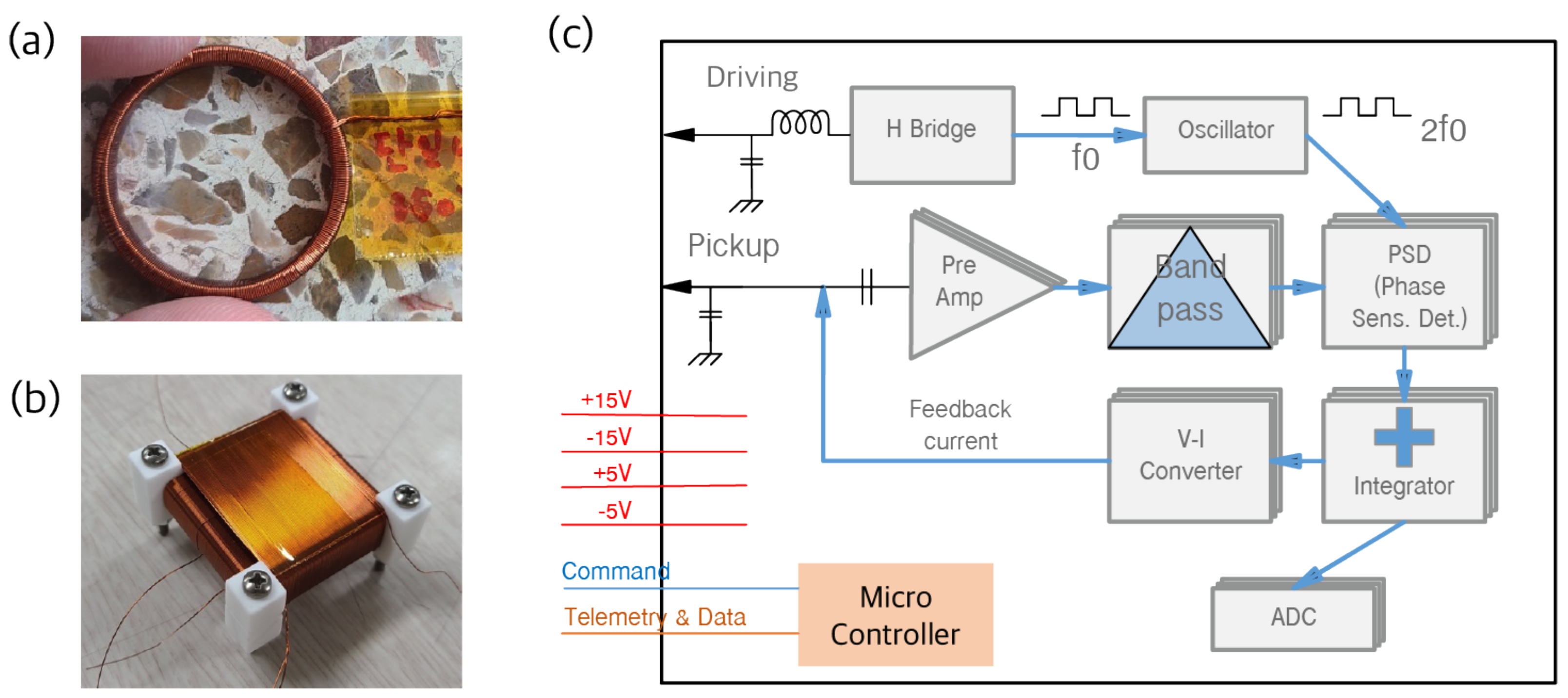
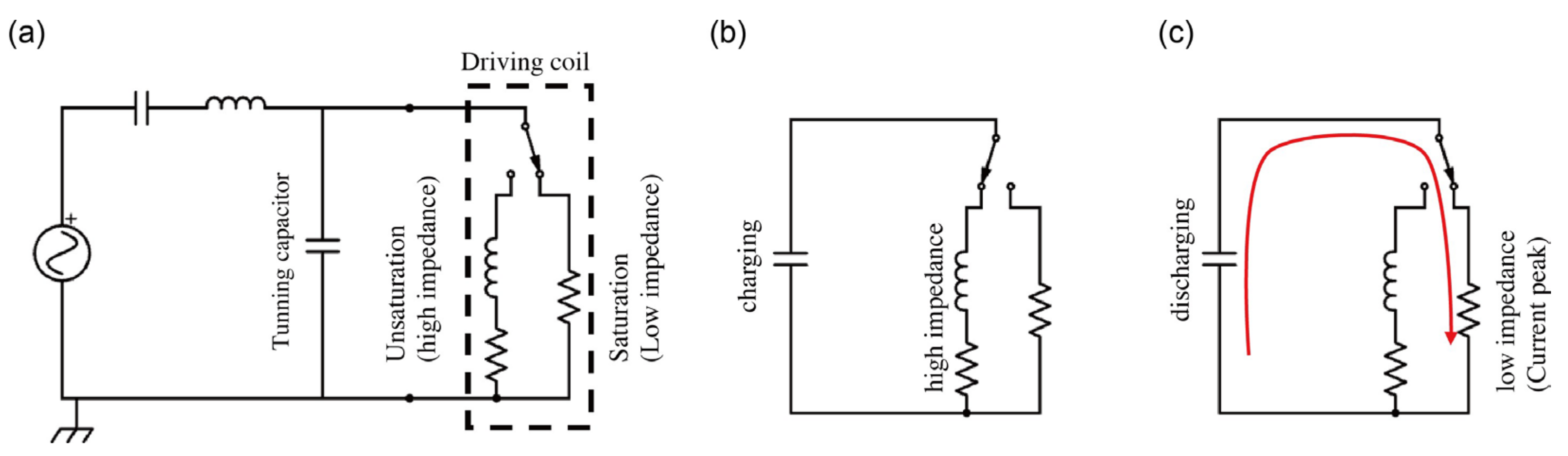
3.2. Fluxgate Electronics Design

The electronics of the AIMAG largely comprise driving, pick-up, and feedback circuits, as shown in Figure 5. The driving circuit, which provides steep currents to the driving coil, shown in Figure 5a, is an important component because it directly affects performance indicators such as power efficiency, output repeatability and noise [3]. In the case of the pick-up coil, shown in Figure 5b, information on the magnitude of the measured magnetic field is contained in even harmonic components that are revealed at the output. Consequently, the noise and accuracy of the measuring magnetic field depend on how this signal is processed. The ferromagnetic material used as the sensor core has nonlinear characteristics; thus, the relation between the amplitudes of the pick-up signal and the actual magnetic field is also nonlinear. The magnitude of the magnetic field is obtained through an integrator, and then the current to cancel out the external magnetic field is fed back through the pick-up coil so that the magnetic field of the sensor core is always maintained at zero. The final output of the circuit is the feedback current, which cancels out the external magnetic field. It is read out by the ADC, which is controlled by a microcontroller, as shown in Figure 5c.
The driving circuit imposes an alternating current into the sensor core to drive the fluxgate. For the fluxgate’s output to operate stably, the AC current must be driven by a large amplitude so that the ferromagnetic material of the sensor core can be sufficiently deeply saturated. Otherwise, it cannot remove the remanent effect of the ferromagnetic material, and the steep section of the hysteresis loop of the ferromagnetic core becomes nonreproducible, resulting in an unreliable output [25,26,27]. Fine-tuning of the appropriate capacitors in parallel to the driving coil should be executed to supply the current sufficiently. Figure 6a shows the equivalent circuit of the tuning capacitor and the driving coil. As shown in Figure 6b, when the core is in the unsaturated state, little current flows due to its high permeability, and the parallel capacitor is charged. When the core is sufficiently saturated, its impedance becomes small, and the parallel capacitor is discharged to supply a strong current, as shown in Figure 6c. Using the tuning capacitor, the driving current can be shaped appropriately for the driving frequency, and the power consumption for the driving current can be substantially reduced.
For the pick-up circuit, there are two known methods to detect the pick-up signal of a fluxgate magnetometer: the voltage output method and the current output method. The AIMAG adopts the voltage output method, which has more heritage and accordingly has more references and is easier to employ. The disadvantage of this method is that it is an open circuit, and the parasitic capacitor component between the coils will thus inevitably affect its performance. The parasitic component causes a ringing in the signal, and the offset is affected by temperature change. To solve this problem, we stabilize the broadband signal at the second-harmonic frequency with an appropriate tuning capacitor for the pick-up circuit [28]. A PSD (phase-sensitive detector) circuit was utilized to minimize noise and enable accurate measurements. The newly devised feature of the AIMAG is the adoption of a zero-crossing detector in the PSD. Although the pick-up signal filtered at the second harmonic frequency has the advantage of amplification, the phase of the pick-up signal may change depending on temperature because the phase frequency response at the second harmonic frequency of the pickup coil tuned to that frequency changes very rapidly (see Section 4.3 for a more detailed description). This effect represents one of the sources of noise in fluxgate magnetometers [15]. Therefore, a zero-crossing detector was employed to eliminate the effects of phase changes. However, since the polarity of the magnetic field cannot be known from the zero-crossing signal of the pick-up signal alone, a dual-edge D-flip-flop with a second harmonic reference signal containing the information as D and the zero-crossing signal as CLK was adopted to measure the polarity of the magnetic field. The phrase ‘Adaptive In-phase’ in AIMAG refers to this aspect.
Figure 7 shows the traditional pick-up circuit triggered by the 2f0 reference signal and the newly devised adaptive in-phase concept utilizing zero-crossing detection and switching by a dual-edge D flip-flop. In the case of the traditional pick-up circuit shown in Figure 7a, the output from the pick-up coil can have a phase delay, and hence, the switched signal triggered by the 2f0 reference can be distorted when the phase delay is relatively large. In the case of a 90◦ phase delay, the switched signal loses most of the polarity information of the pick-up signal. In contrast, if the pick-up signal is switched by the zero-crossing reference signal and the polarity is determined by the 2f0 reference signal, as depicted in Figure 7b, then the feedback control can be functional even when the phase delay approaches 90°. Thus, the adaptive in-phase concept is expected to be tolerant to phase changes caused by thermal distortion and to have a wider frequency range (f0). The trade-off study to optimize and stabilize the fluxgate in terms of driving frequency (f0) and pick-up frequency (2f0) will be described in Section 4.3 below.
Finally, a feedback circuit was employed to eliminate the nonlinear effect. Since the magnetic materials used for the ring core have nonlinear responses, the output has a short linear section and is strongly influenced by the thermal coefficients of the sensor core and amplifiers. In the early days of applying feedback systems, only a resistor (combined with something) was used as a V-I converter [3]. The problem of such a circuit was that the output of the sensor changes severely due to thermal expansion of the sensor. Then, trans-conductance amplifiers were utilized to compensate for the thermal expansion [14]. In addition, this system offers the advantage of being able to flexibly change the dynamic range in elliptical orbit missions or deep space exploration where the magnetic field environment changes severely. As shown in Figure 5c above, the AIMAG applies a feedback system that takes the integrator signal as an input to the transconductance amplifier, denoted as the V-I converter in the electronics configuration. For digitization of the data, an LTC2440 ADC chip, with characteristics of a 24 bit digital resolution and an oversampling function, was utilized. For a stable voltage reference for the ADC, an LTZ1000 voltage reference, which shows superior tolerance to the thermal changes in space, was used in the AIMAG readout system. For components with unverified radiation tolerance, such as the LTC2440, total ionizing dose testing will be performed to verify their suitability for the proposed application.

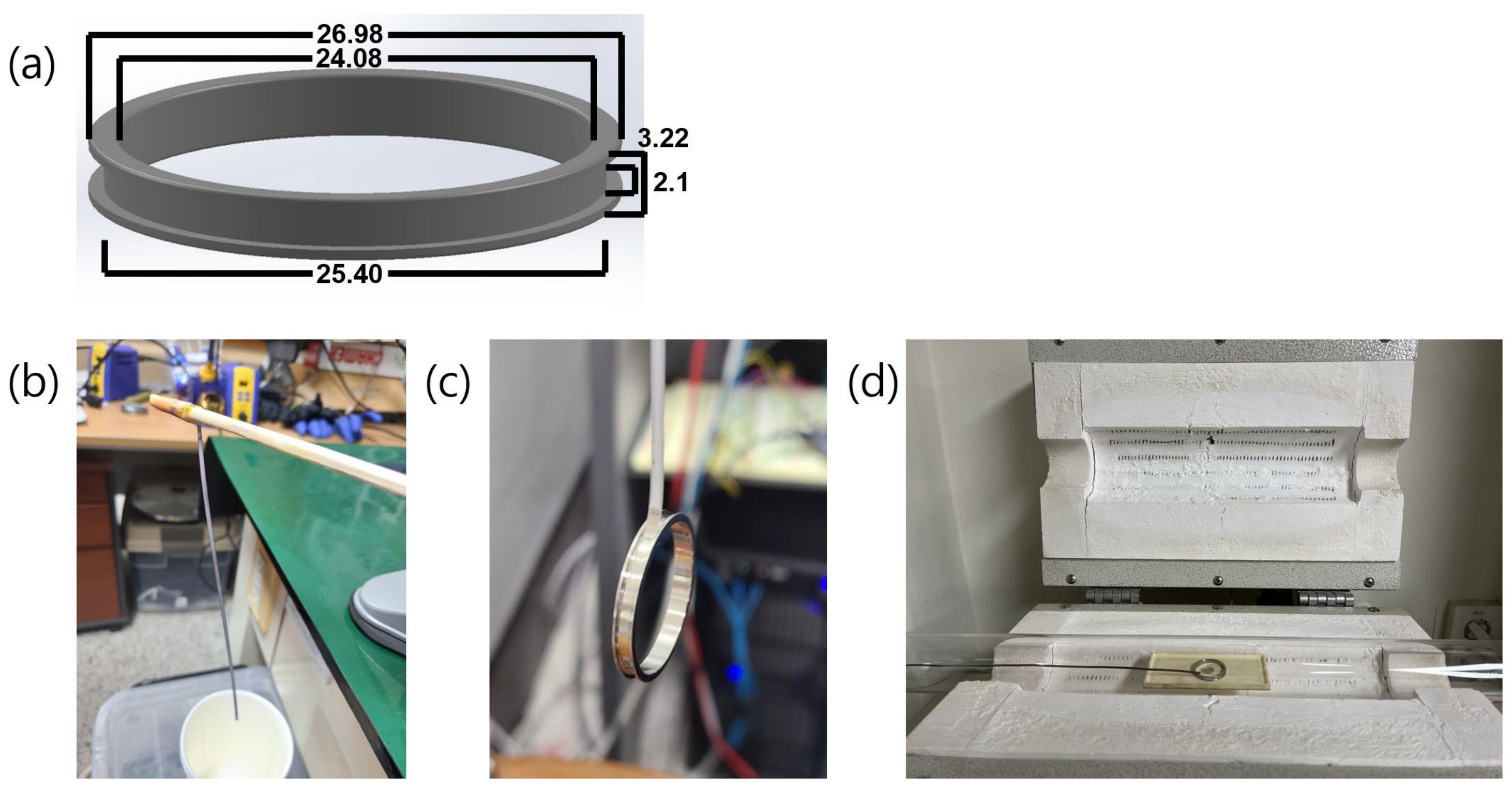
3.3. Fluxgate Sensor Core Design

A fluxgate sensor generally comprises a ferromagnetic core with a primary driving winding and a secondary pick-up coil (Figure 5a,b). Historically, several ferromagnetic materials have been employed in such fluxgate ring cores (Figure 8a). Among these materials, permalloy has been widely used in space-borne fluxgate magnetometers, manufactured from a single batch of 6-81 permalloy containing 6% molybdenum, 81.3% nickel and the remainder iron [29]. This permalloy is not commercially available; thus, alternate materials were surveyed, and amorphous Co-based alloys with quasizero magnetostriction were identified to be suitable for magnetic cores operating at a high frequency [30]. For the magnetic core of the AIMAG, we chose a 2 mm-wide Metglas 2714A amorphous alloy ribbon with a composition of CobalFe4Ni2Si15B15 (Figure 8b,c) due to its characteristics of a low core loss, high permeability, a low coercive force, near-zero magnetostriction, and excellent corrosion resistance. A low coercive force or high squareness, defined by the ratio between remanence (Br) and saturation induction (Bs) in the B–H loop, is required to secure a high performance of the sensor.
To reduce the coercive force and obtain a higher permeability, we applied a two-step cooling thermal treatment [31] to Metglas 2714A (Figure 8d). Specifically, 2714A was annealed at 440 degrees for 20 min. The cooling was performed in two steps. The first step is a furnace cooling process. This slow cooling was followed by a second step of a rapid cooling process before the sample reached the Curie temperature [31]. During this process, Mg(OH)2 is converted to MgO, an insulator, through a dehydration process. The heat-treated ferromagnet has a high squareness and low coercivity. As shown in Table 2, the coercive force improved 3.5-fold due to the heat treatment, and this can be expected to reduce the AIMAG power consumption. The squareness also improved by a factor of ~2.2. This results in a high driving current pickup and low power consumption. This is essential for improving the resolution of the sensor by ameliorating the quality of the fluxgate pick-up signal.
The driving ring core bobbin should be made of a nonmagnetic material and capable of firmly supporting the ferromagnetic core without imposing stress on the ferromagnetic material. In particular, a slight deformation in the ferromagnetic element significantly increases the magnetic noise. Thus, the difference in the coefficients of linear thermal expansion (CLTE) of the bobbin and ferromagnetic core materials can increase magnetic noise due to mechanical stress on the ferromagnetic materials in space environments with a wide temperature range [29]. MACOR machinable ceramic (®Corning, Corning, NY, USA) has been widely used as a fluxgate bobbin material. This material offers high thermal insulation (1.46 W/m/K) and very low thermal deformation (9.3 µm/m-°C). For the driving ring core bobbin of the AIMAG, Inconel X-750 (Carpenter Technology Co., Reading, PA, USA) was chosen for its high structural stability with a high density of 8.28 g/cm3 and a CLTE of 12.6 mm/m-°C, very similar to that of Metglas 2714A (12.7 mm/m-°C), which minimizes thermal deformation. In many satellite fluxgates, low noise was achieved by using form factors from legacy Infinetics S1000 ring cores. These ring cores have an outer diameter of approximately 25 mm and are wound 4–16 times around a 1–2 mm ferromagnet ribbon [27,29]. However, the material has long been discontinued, and therefore, the AIMAG mimics the design of the low-noise fluxgate based on its similar dimensions and form factor, as shown in Figure 8a.
It is known that demagnetization, which occurs due to the ferromagnetic shape and eddy current inside a ferromagnetic material generated by AC current, causes core loss inside the ring core, which degrades the efficiency of the fluxgate. To prevent this, we devised a ribbon roll ring core that reduces the cross-section of the ferromagnetic body and increases the effective length, which has been widely used in space magnetometers [29]. A ribbon of Metglas 2714A amorphous alloy, 2 mm wide and 20 µm thick, was coated with Mg(OH)2, also known as milk of magnesia, as shown in Figure 8b. It was spot-welded to the ring core, as shown in Figure 8c, and wound six times in the poloidal direction.
The pick-up bobbin serves to fix the driving core and to wind the pick-up coil. Since the AIMAG is a feed-back fluxgate magnetometer, as introduced in Section 3.2 above, it drives the current such that the magnetic field inside the pick-up coil is always zero [14]. If the CLTE of the pick-up bobbin material is large, then the coil constant changes significantly, and thus, the temperature change significantly affects the magnetic field measurement. The AIMAG pick-up bobbin comprises MACOR ceramic, which has a low CLTE of 9.3 µm/m-°C.

4. Analysis of AIMAG Performance

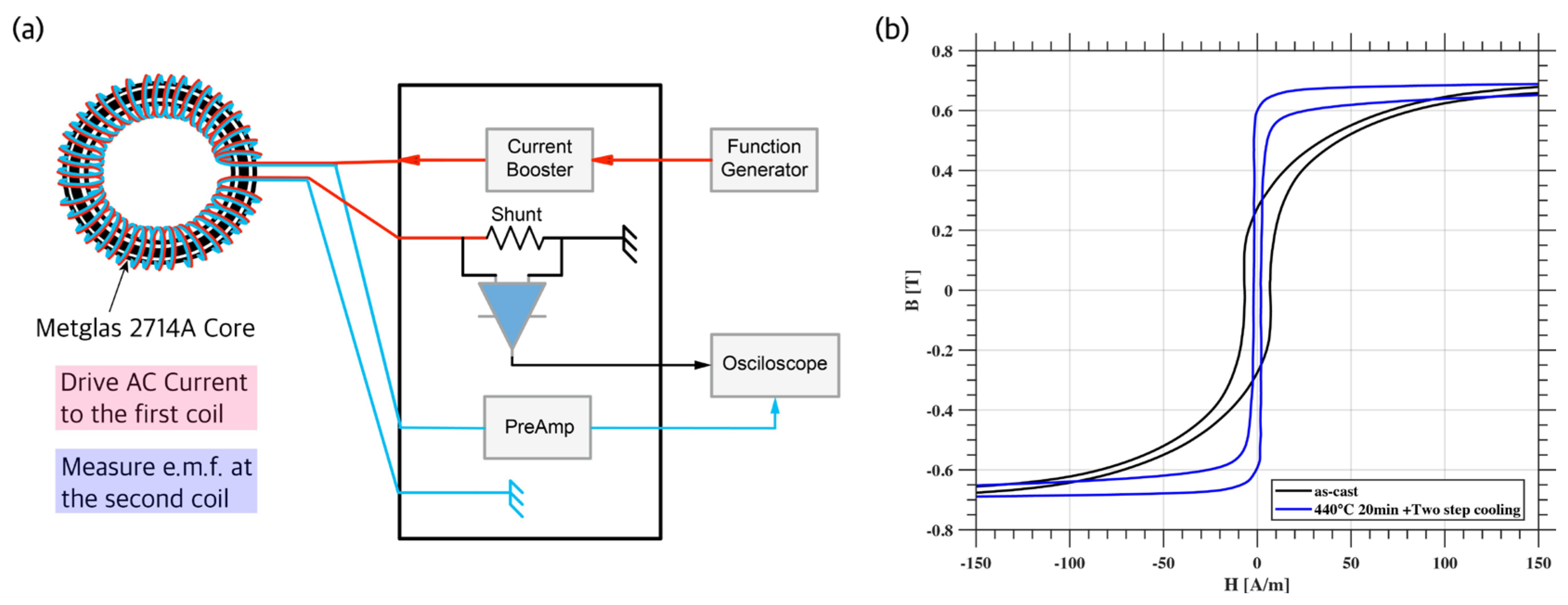
4.1. Hysteresis Characteristics

The AIMAG fluxgate sensors adopt a ring core design, which comprises a ferromagnetic ring core made of Metglas 2714A, a driving coil and a pick-up coil. A square-wave signal with 9 to 10 kHz is imposed in the driving coil, which is wound around the ring core with a torus geometry. The actual current in the driving coil has a short peak shape (not shown here) which means the coil has a suitable inductance. The magnetic field formed in the ring core by the driving current is along a circle in the clockwise or counterclockwise direction according to the polarity of the current. The pick-up coil, which is wound in the plane containing the ring core, senses the difference between the bidirectional components of the induced current. When there is no external B-field, the electromotive force in the pick-up coil is essentially zero, whereas in the presence of an external field, the net signal increases according to the direction and strength of the external field.
In the pick-up coil, a DC bias current is added to cancel out the external magnetic field imposed in the ring core. This feedback control scheme can extend the detection range and improve the sensitivity and linearity of the fluxgate. The pick-up signal is proportionally sensitive to the steepness of the B–H loop, that is, the hysteresis characteristics. Therefore, it is very important to use ferromagnetic materials with hysteresis characteristics indicating a low coercive force or high squareness in the B–H loop.
We analyzed the hysteresis characteristics of the AIMAG sensors by devising a dedicated circuit to measure the B–H curve, as presented in Figure 9a. Two coils are wound around the ring core, one of which is used for driving AC current and the other of which is used for measuring the electromotive force induced by the current. As described in Section 3.3 above, the final sensors underwent heat treatment. To check the improvement in hysteresis characteristics after the heat treatment, H–B curves were obtained and compared between the two cases with and without heat treatment. The results are shown in Figure 9b, where the black line represents the hysteresis curve measured without the heat treatment process (designated as ’as-cast’) and the blue line is for the hysteresis curve after the heat treatment. In the case of ’as-cast’, the area encompassed by the hysteresis curve is larger than that for the case of heat treatment, and the transition to the saturation state is slower than in the case of heat treatment. The coercivity, as defined by the value of the H-field when the magnetic B-field is inside the ferromagnetic core, is substantially reduced after thermal treatment. Thus, the sensitivity of the fluxgate sensors is improved.

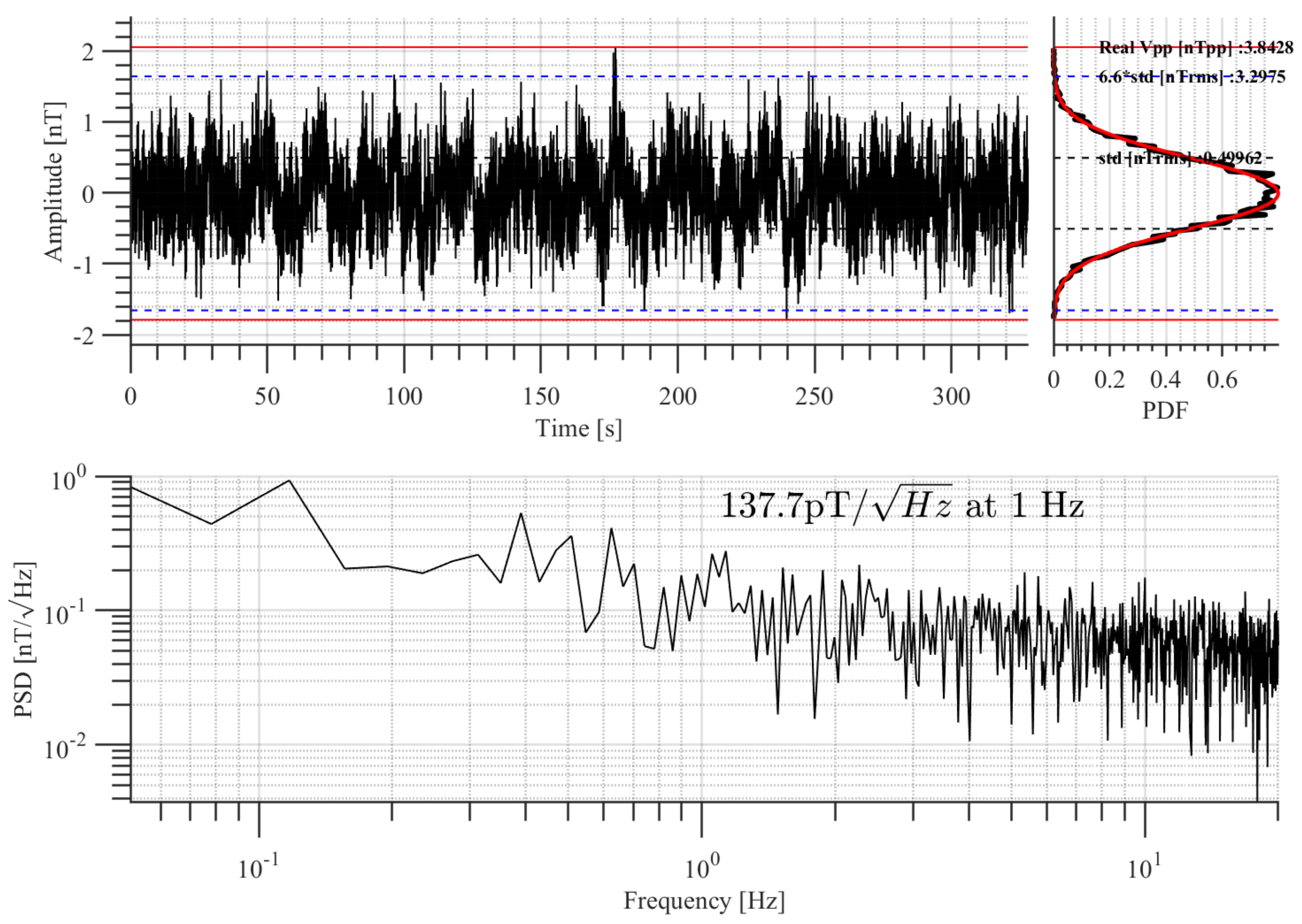
4.2. Noise Level Measurement

The noise magnitude of the AIMAG is one of the most important factors to secure the measurement accuracy required for detecting EEJ signatures. The noise characteristics of the AIMAG were measured in a three-layer µ-metal magnetic shielding can (TLMS-C100), which reduces the ambient magnetic disturbance by a factor of 1/1000. The dynamic range was adjusted to ±50,000 nT during the test, and data were obtained for 300 s with a sampling rate of 40 sps (samples per second). Figure 10 shows the measured noise amplitude and its power spectrum. In this experiment, we achieved noise levels of PSD = ~150 p T / H z and an amplitude = ~500 pT (RMS). These values satisfy the technical requirements of 300 pT/Hz and 1 nT (RMS) or less shown in Table 1 above.

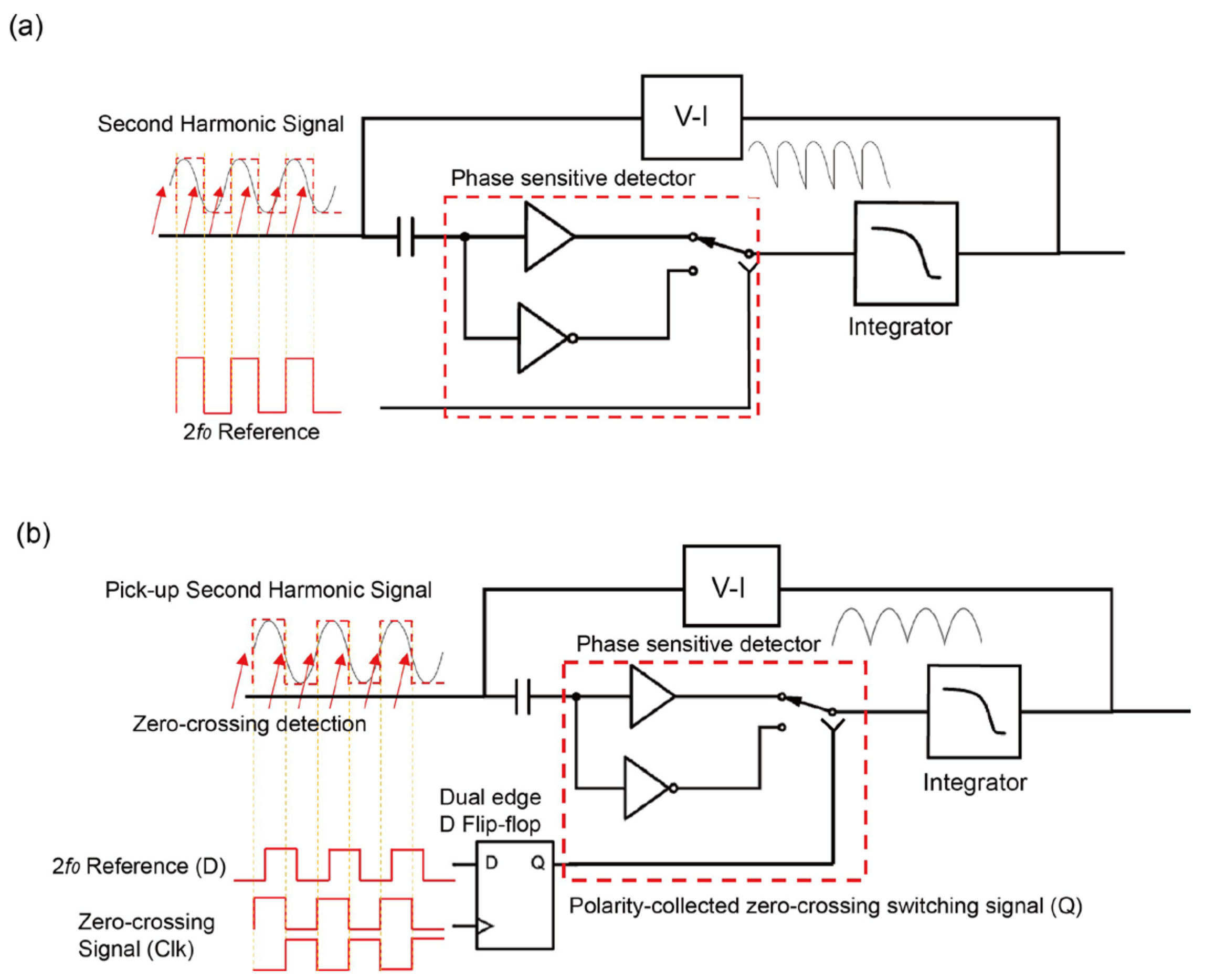
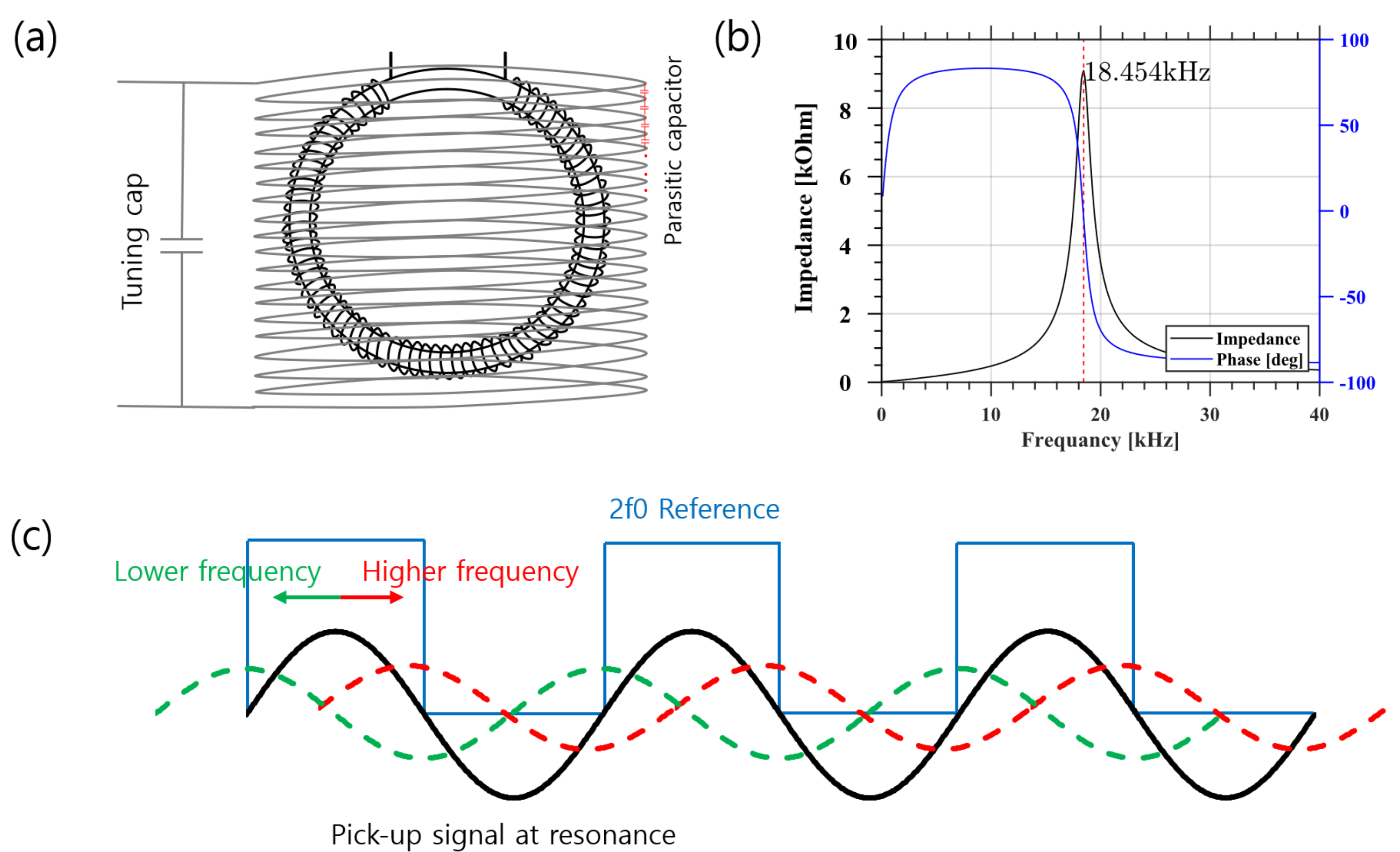
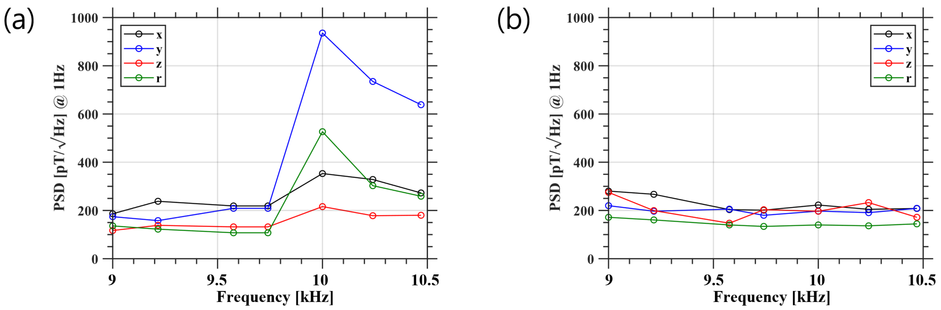
4.3. Optimization by an Adaptive In-Phase Circuit

The adaptive in-phase circuit is one of the most important features of the AIMAG. We evaluated its performance by comparing it with a typical fluxgate circuit without an adaptive in-phase function. As shown in Figure 11a, the pick-up coil of a voltage output-type fluxgate has an unintended parasitic capacitor. This causes unintended odd-order ringing, signal instability, and temperature dependence. This issue is resolved by connecting a properly sized tuning capacitor in parallel with the pick-up coil. The tuning capacitor stabilizes the signal and focuses the broadband signal onto the second-harmonic frequency [28]. Figure 11b shows a plot of impedance measurements to determine the resonance frequency of the sensor core. The black line shows the resonance frequency centered at 18.4 kHz. At the resonance frequency, the signal peaks, but the phase has a steep slope, as indicated by the blue line. Figure 11c shows the variation in the relative phase between the 2f0 reference signal (blue square wave) and the second harmonic signals with different frequencies. The black line shows the in-phase state, which is when the second harmonic signal is exactly at the resonance frequency of the pick-up coil. A higher (lower) frequency signal phase shifts to the right (left) relative to the 2f0 reference signal, as shown by the red (green) line.
The relative phase of the signal can affect the noise magnitude. To evaluate such an effect, the output noise powers were compared between a typical fluxgate circuit without an adaptive in-phase function and a circuit with an adaptive in-phase function. This task was motivated by a report on the temperature effect [15], in which the fluxgate second harmonic signal suffered from a phase shift of approximately 0.7°/°C below 20 °C, which can increase the noise levels. By comparing two cases of fluxgate circuits, we demonstrate the importance of phase correction. This comparison was performed by varying the driving frequency, which ultimately corresponds to changing the pick-up signal phase. Note that a deviation in the second harmonic frequency of 1 kHz, for example, corresponds to a phase change of >60 degrees in Figure 11b. The driving circuit uses a tuned capacitor such that the current can be supplied most effectively at 9.2 kHz. When the driving frequency is changed, the phase of the driving current changes with respect to the 2f0 reference signal, and the phase of the pick-up signal changes accordingly. Figure 12a shows the noise power spectrum obtained with the typical circuit. Measurements were taken in each of the x, y, z and r axes. The results for all axes show that the noise is flat until 9700 Hz, after which it increases sharply. This result occurs because the signal’s response magnitude decreases outside of the pick-up’s resonance frequency and the signal’s phase becomes out of phase with the 2f0 reference signal. Figure 12b shows the noise power spectrum for the adaptive in-phase circuit. The noise PSD levels in all axes lie between 100 and 300 p T / H z around our target frequency of 9.2 kHz. A comparison of Figure 12a,b shows that the adaptive in-phase circuit effectively provides adaptive phase correction. Furthermore, we consider that our adaptive in-phase circuit is more effective than a phase correction process based on a look-up table constructed by real-time temperature monitoring [15]. However, the noise of the adaptive in-phase circuit is 10–50 pT higher in the relatively in-phase state, which is a problem caused by the inability to effectively remove the digital noise generated by the dual-edge D-flip-flop. This aspect should be improved in the future.

5. Summary and Future Works

In summary, we report on key aspects of the design and performance for the fluxgate magnetometers, AIMAG, which are set to be onboard the CAS500-3 satellite when it is launched in 2025. First, we determined the performance specifications required for the main science objectives, that is, the EIA and EEJ, which should meet a resolution of 1 nT (RMS) or less and a noise level of 300 pT/√ Hz or less. We then verified that the manufactured AIMAG indeed meets these requirements due to the performance of certain key technologies that we adopted. One of these technologies is a two-step cooling heat treatment that was performed on the ferromagnet sensor. The heat treatment process was successful enough to ensure effective hysteresis characteristics with low coercivity and high squareness, consequently allowing a high driving current pickup and low power consumption.
Most importantly, the AIMAG circuit adopted an adaptive in-phase function. This is the most critical feature of the AIMAG, which distinguishes it from common fluxgate magnetometers. This feature was motivated by the report in [15], wherein extreme temperature conditions caused the phase of the fluxgate’s pick-up signal to change rapidly, significantly affecting the output noise. It is difficult to manually (e.g., using a look-up table) adjust the phase of the pick-up coil under such a harsh environment. Our circuit with an adaptive in-phase function of the AIMAG largely resolves this challenge.
Several future works are planned before the launch of the satellite. First, although the AIMAG’s adaptive function is effective, the dual edge D-flip-flop is a digital device, and therefore, it contributes noise to the analog signal, which should be removed through further system optimization. Second, we plan to perform environmental stability experiments across the extreme temperature range that the AIMAG will actually experience in orbit. For this purpose, calibration will be performed with a three-axis Helmholtz coil system in an environment where the temperature can be adjusted. Third, a precise alignment test will be performed through the stages of EQM and FM development to improve the overall performance. Finally, one of the notable features of the AIMAG is that three fluxgate magnetometers will be onboard the CAS-500-3 satellite. We expect that this set of three magnetometers will allow us to effectively eliminate magnetic disturbances from the satellite. A specific report on this feature is in progress, the results of which will be reported elsewhere.

Author Contributions

Conceptualization, S.L.; methodology, S.L., K.R. and D.L.; software, S.P. (Seongog Park), J.H.; validation, S.L. and D.C.; formal analysis, S.L.; data curation, S.L. and D.C.; resources, S.L., J.K., B.K., W.C., S.P. (Suhwan Park) and C.C.; writing—original draft preparation, S.L.; writing—review and editing, S.L., K.R. and D.L.; visualization, S.L. and E.J.; supervision, D.L.; project administration, K.R.; funding acquisition, K.R. All authors have read and agreed to the published version of the manuscript.

Funding

This research was funded by the National Research Foundation of Korea (NRF-2021M1A3A4A06086639 and NRF-2019R1A2C1003140).

Data Availability Statement

The SWARM data were obtained via the SWARM PDGS (https://swarm-diss.eo.esa.int/, accessed on 27 January 2022) operated by ESA. The authors made use of IGRF-13 provided by the International Association of Geomagnetism and Aeronomy (IAGA) in the data analysis. We also made use of the EEJ model (EEJM2.0) provided by the CIRES/NCEI geomagnetism team available online at http://models.geomag.us/EEJ.html (accessed on 1 March 2022) and http://www.earthref.org.

Acknowledgments

This study was supported by the Satellite Development Program through the National Research Foundation of Korea (NRF) funded by the Ministry of Science and ICT (NRF- 2021M1A3A4A06086639). D.-Y. Lee acknowledges support from the National Research Foundation of Korea under grant NRF-2019R1A2C1003140. The authors would like to express their special thanks to the engineers involved in the CAS500-3 mission and KSLV development.

Conflicts of Interest

The authors declare no conflict of interest.

Abbreviations

The following abbreviations are used in this manuscript:
AIMAG  Adaptive In-phase MAGnetometer
CAS500-3  The Third Compact Advanced Satellite 500
CLTE  Coefficients of Linear Thermal Expansion
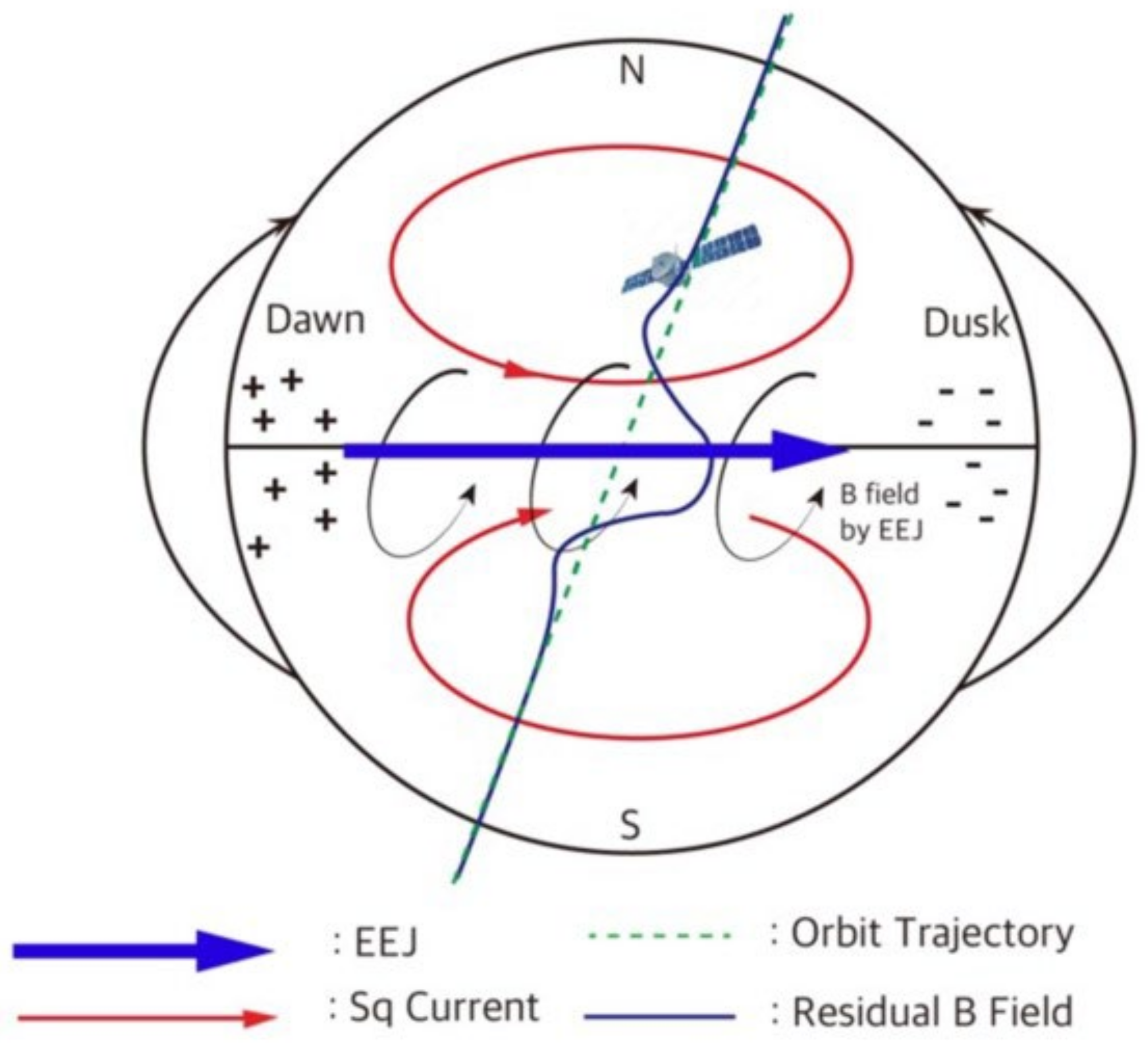
EEJ  Equatorial Electrojet
EEJM  Equatorial Electrojet Model
EIA  Equatorial Ionization Anomaly
EQM  Engineering Qualification Model
FM  Flight Model
IAMMAP  Ionospheric Anomaly Monitoring by Magnetometer And Plasma-probe
IGRF  International Geomagnetic Reference Field
KSLV  Korean Space Launch Vehicle
PSD  Phase Sensitive Detector
RMS  Root Mean Square

References

  1. Chapman, S. The equatorial electrojet as detected from the abnormal electric current distribution above Huancayo, Peru, and elsewhere. Arch. Meteorol. Geophys. Bioklimatol. Ser. A 1951, 4, 368–390. [Google Scholar] [CrossRef]
  2. Ness, N.F. Magnetometers for space research. Space Sci. Rev. 1970, 11, 459–554. [Google Scholar] [CrossRef]
  3. Acuna, M. Fluxgate magnetometers for outer planets exploration. IEEE Trans. Magn. 1974, 10, 519–523. [Google Scholar] [CrossRef]
  4. Auster, H.U.; Glassmeier, K.H.; Magnes, W.; Aydogar, O.; Baumjohann, W.; Constantinescu, D.; Fischer, D.; Fornacon, K.H.; Georgescu, E.; Harvey, P.; et al. The THEMIS Fluxgate Magnetometer. Space Sci. Rev. 2008, 141, 235–264. [Google Scholar] [CrossRef]
  5. Appleton, E.V. Two Anomalies in the Ionosphere. Nature 1946, 157, 691. [Google Scholar] [CrossRef]
  6. Yamazaki, Y.; Maute, A. Sq and EEJ—A Review on the Daily Variation of the Geomagnetic Field Caused by Ionospheric Dynamo Currents. Space Sci. Rev. 2017, 206, 299–405. [Google Scholar] [CrossRef]
  7. Namba, S.; Maeda, K.I. Radio Wave Propagation; Corona: Tokyo, Japan, 1939. [Google Scholar]
  8. Moffett, R.J.; Hanson, W.B. Effect of Ionization Transport on the Equatorial F-Region. Nature 1965, 206, 705–706. [Google Scholar] [CrossRef]
  9. Ryu, K.; Lee, S.; Woo, C.H. Design and validation of impedance probe for platform-independent ionospheric plasma diagnostics. Curr. Appl. Phys. 2023, 51, 71–79. [Google Scholar] [CrossRef]
  10. Aschenbrenner, H.; Goubau, G. Eine Anordnung zur Registrierung rascher magnetischer Störungen. Hochfrequenztech. Elektroakust. 1936, 47, 177–181. [Google Scholar]
  11. Geyger, A.W. The ring-core magnetometer “A new type of second-harmonic flux-gate magnetometer”. Trans. Am. Inst. Electr. Eng. Part I Commun. Electron. 1962, 81, 65–73. [Google Scholar] [CrossRef]
  12. Gordon, D.; Lundsten, R.; Chiarodo, R.; Helms, H. A fluxgate sensor of high stability for low field magnetometry. IEEE Trans. Magn. 1968, 4, 397–401. [Google Scholar] [CrossRef]
  13. Dolginov, S.S.; Zhuzgov, L.N.; Selyutin, V.A. Magnetometers in the Third Soviet Earth Satellite. Artif. Earth Satell. 1960, 4, 358–396. [Google Scholar]
  14. Acuña, M.; Scearce, C.; Seek, J.; Scheifele, J. The MAGSAT Vector Magnetometer: A Precision Fluxgate Magnetometer for the Measurement of the Geomagnetic Field; Technical report, GSFC; NASA: Washington, DC, USA, 1978. [Google Scholar]
  15. Nishio, Y.; Tohyama, F.; Onishi, N. The sensor temperature characteristics of a fluxgate magnetometer by a wide-range temperature test for a Mercury exploration satellite. Meas. Sci. Technol. 2007, 18, 2721. [Google Scholar] [CrossRef]
  16. Miles, D.M.; Mann, I.R.; Kale, A.; Milling, D.K.; Narod, B.B.; Bennest, J.R.; Barona, D.; Unsworth, M.J. The effect of winding and core support material on the thermal gain dependence of a fluxgate magnetometer sensor. Geosci. Instrum. Methods Data Syst. 2017, 6, 377–396. [Google Scholar] [CrossRef]
  17. Zhou, B.; Cheng, B.; Gou, X.; Li, L.; Zhang, Y.; Wang, J.; Magnes, W.; Lammegger, R.; Pollinger, A.; Ellmeier, M.; et al. First in-orbit results of the vector magnetic field measurement of the high precision magnetometer onboard the china seismo-electromagnetic satellite. Earth Planets Space 2019, 71, 119. [Google Scholar] [CrossRef]
  18. Alken, P.; Maus, S. Spatio-temporal characterization of the equatorial electrojet from CHAMP, Ørsted, and SAC-C satellite magnetic measurements. J. Geophys. Res. Space Phys. 2007, 112, A09305. [Google Scholar] [CrossRef]
  19. Thomas, N.; Vichare, G.; Sinha, A. Characteristics of equatorial electrojet derived from Swarm satellites. Adv. Space Res. 2017, 59, 1526–1538. [Google Scholar] [CrossRef]
  20. Ryu, K.; Kwak, Y.; Kim, Y.H.; Park, J.; Lee, J.; Min, K. Variation of the topside ionosphere during the last solar minimum period studied with multisatellite measurements of electron density and temperature. J. Geophys. Res. Space Phys. 2016, 121, 7269–7286. [Google Scholar] [CrossRef]
  21. Forbes, J.M.; Russell, J.; Miyahara, S.; Zhang, X.; Palo, S.; Mlynczak, M.; Mertens, C.J.; Hagan, M.E. Troposphere-thermosphere tidal coupling as measured by the SABER instrument on TIMED during July–September 2002. J. Geophys. Res. Space Phys. 2006, 111, A10S06. [Google Scholar] [CrossRef]
  22. Macmillan, S.; Olsen, N. Observatory data and the Swarm mission. Earth Planets Space 2013, 65, 15. [Google Scholar] [CrossRef]
  23. Alken, P.; Thébault, E.; Beggan, C.D.; Amit, H.; Aubert, J.; Baerenzung, J.; Bondar, T.N.; Brown, W.J.; Califf, S.; Chambodut, A.; et al. International Geomagnetic Reference Field: The thirteenth generation. Earth Planets Space 2021, 73, 49. [Google Scholar] [CrossRef]
  24. Constantinescu, O.D.; Auster, H.U.; Delva, M.; Hillenmaier, O.; Magnes, W.; Plaschke, F. Principal Component Gradiometer technique for removal of spacecraft-generated disturbances from magnetic field data. Geosci. Instrum. Methods Data Syst. Discuss. 2020, 2020, 1–26. [Google Scholar] [CrossRef]
  25. Liu, Y.; Sellmyer, D.; Shindo, D. Handbook of Advanced Magnetic Materials: Vol 1. Nanostructural Effects; Developments in Hydrobiology Series; Springer: New York, NY, USA, 2008. [Google Scholar] [CrossRef]
  26. Tang, S.; Duffy, M.; Ripka, P.; Hurley, W. Excitation circuit for fluxgate sensor using saturable inductor. Sens. Actuators A Phys. 2004, 113, 156–165. [Google Scholar] [CrossRef]
  27. Ripka, P. Fluxgate Sensors. In Magnetic Sensors and Magnetometers, 2nd ed.; Ripka, P., Magnes, W., Eds.; Artech House: Norwood, MA, USA, 2021. [Google Scholar]
  28. Ripka, P.; Billingsley, S. Fluxgate: Tuned vs. untuned output. IEEE Trans. Magn. 1998, 34, 1303–1305. [Google Scholar] [CrossRef]
  29. Miles, D.M.; Ciurzynski, M.; Barona, D.; Narod, B.B.; Bennest, J.R.; Kale, A.; Lessard, M.; Milling, D.K.; Larson, J.; Mann, I.R. Low-Noise Permalloy Ring-Cores for Fluxgate Magnetometers. Geosci. Instrum. Methods Data Syst. Discuss. 2019, 8, 227–240. [Google Scholar] [CrossRef]
  30. Tsai, C.S.; Yang, W.J.; Leu, M.S.; Lin, C.S. High frequency characteristics of annealed Co-base amorphous alloy ribbons. J. Appl. Phys. 1991, 70, 5846–5848. [Google Scholar] [CrossRef]
  31. Yang, J.; Kim, Y.; Ryu, K.; Kim, M.; Chung, Y.; Kim, T. Enhancement of permeability of Co-based amorphous alloy by two-step cooling method. J. Magn. Magn. Mater. 2000, 222, 65–69. [Google Scholar] [CrossRef]
Figure 1. Schematic illustration of the equatorial electrojet (EEJ) and Sq currents. See the text in Section 1 and Section 2 for a detailed description.
Remotesensing 15 04829 g001
Figure 2. Variation in EEJ intensity at solstices and equinoxes as a function of local time based on EEJM-2. (a) March Equinox, (b) June Solstice, (c) September Equinox and (d) December Solstice.
Remotesensing 15 04829 g002
Figure 3. (a) The observation geometry of the EEJ with the geomagnetic field configuration (the same figure as Figure 1, repeated here for convenience). (b,c) Samples of the EEJ derived from the SWARM satellite with (b) small and (c) large amplitudes.
Remotesensing 15 04829 g003
Figure 4. (a) Mechanical configuration of the CAS500-3 satellite and locations of AIMAG fluxgate sensors. (b) Mechanical design of the AIMAG fluxgate magnetometers. (c) Manufactured prototype of the AIMAG fluxgate magnetometers.
Remotesensing 15 04829 g004
Figure 5. (a) A driving coil wound around the ring core. (b) A pickup coil wound around the driving coil. (c) The electronics configuration of the AIMAG fluxgate magnetometers.
Remotesensing 15 04829 g005
Figure 6. (a) Equivalent circuit of the driving part. (b,c) show the circuit behavior for the cases of high impedance (unsaturated) and low impedance (saturated), respectively. The red arrow in (c) represents the discharging current from the tuning capacitor which helps the peak shaping as well as saves the power consumption.
Remotesensing 15 04829 g006
Figure 7. (a) Traditional phase-sensitive switch for a feedback integrator operated by a 2f0 reference signal. (b) Adaptive in-phase control by a zero-crossing signal using a dual-edge D flip-flop. The yellow dashed lines mean the PSD switching timing, while the red solid lines represent the 2f0 reference and zero-crossing signals.
Remotesensing 15 04829 g007
Figure 8. (a) Dimensions of the AIMAG ring core in units of mm. (b) 2714A coated with Mg(OH)2. (c) 2714A spot-welded AIMAG ring core. (d) Heat treatment of the AIMAG ring core.
Remotesensing 15 04829 g008
Figure 9. (a) Schematic of the setup to measure the B–H curve on the 2714A core. (b) Comparison of B–H curves of the 2714A between as-cast (black) and after heat treatment (blue).
Remotesensing 15 04829 g009
Figure 10. Time series data and noise analysis of AIMAG in a magnetic shielding can. The red solid lines mean peak-to-peak amplitudes, while the blue dashed lines mean the 6.6σ (99.9%) noise peak-to-peak limits and the black dashed lines mean 1σ (68.27%) limits, respectively.
Remotesensing 15 04829 g010
Figure 11. (a) Fluxgate sensor schematic. (b) Impedance plot of a pickup coil. (c) Relative phase change of the 2f0 and pick-up signals according to frequency.
Remotesensing 15 04829 g011
Figure 12. (a) Noise variation with frequency in a typical fluxgate analog circuit without an adaptive in-phase function. (b) Noise variation with frequency in a fluxgate analog circuit with an adaptive in-phase function as adopted in the AIMAG. Note that each magnetometer of the AIMAG is equipped with two sensors, and each sensor performs measurements in two axes, resulting in measurements in four axes in total (x, y, z, r). The r-axis is redundant, as it is practically the same as the y-axis.
Remotesensing 15 04829 g012
Table 1. Performance specifications of AIMAG.
Instrument ParameterSpecifications
Measurement Range±65,000 nT
Resolution<1 nT(RMS)
Noise Level<300 p T / H z at 1 Hz
Temperature Coefficient~0.1%/deg.
Table 2. Heat treatment effect.
CaseCoercivity (A/m)Squareness
As-cast6.780.37
After Thermal Treatment1.920.81
Disclaimer/Publisher’s Note: The statements, opinions and data contained in all publications are solely those of the individual author(s) and contributor(s) and not of MDPI and/or the editor(s). MDPI and/or the editor(s) disclaim responsibility for any injury to people or property resulting from any ideas, methods, instructions or products referred to in the content.

