Communication

Pilot Study of Low-Light Enhanced Terrain Mapping for Robotic Exploration in Lunar PSRs

1
Department of Future and Smart Construction Research, Korea Institute of Civil Engineering and Building Technology, Goyang 10223, Republic of Korea
2
Department of Geoinformatic Engineering, Inha University, Incheon 22212, Republic of Korea
*
Author to whom correspondence should be addressed.
Remote Sens. 2023, 15(13), 3412; https://doi.org/10.3390/rs15133412
Submission received: 11 May 2023 / Revised: 3 July 2023 / Accepted: 4 July 2023 / Published: 5 July 2023
(This article belongs to the Special Issue Laser and Optical Remote Sensing for Planetary Exploration)

Abstract

:
The recent discovery of water ice in the lunar polar shadowed regions (PSRs) has driven interest in robotic exploration, due to its potential utilization to generate water, oxygen, and hydrogen that would enable sustainable human exploration in the future. However, the absence of direct sunlight in the PSRs poses a significant challenge for the robotic operation to obtain clear images, consequently impacting crucial tasks such as obstacle avoidance, pathfinding, and scientific investigation. In this regard, this study proposes a visual simultaneous localization and mapping (SLAM)-based robotic mapping approach that combines dense mapping and low-light image enhancement (LLIE) methods. The proposed approach was experimentally examined and validated in an environment that simulated the lighting conditions of the PSRs. The mapping results show that the LLIE method leverages scattered low light to enhance the quality and clarity of terrain images, resulting in an overall improvement of the rover’s perception and mapping capabilities in low-light environments.

1. Introduction

The discovery of water ice in the lunar permanently shadowed regions (PSRs) has driven international space agencies to conduct robotic explorations [1,2,3]. The PSRs are inside impact craters near the lunar south and north poles. As the Moon’s rotation axis is nearly perpendicular to its orbital plane around the Sun, these crater interiors did not receive direct sunlight for geologically long periods of time. Cold and dark environments in the PSRs trapped volatile materials, especially water ice [4,5,6]. In the context of in-situ resource utilization (ISRU) for producing consumable products from native resources, water ice can be utilized to produce oxygen and water for life support or hydrogen for fuel and propellant [7,8]. Thus, water ice is a key resource for enabling long-term sustainable human exploration and habitation.
Planetary rovers have provided in-situ ground imagery for scientific investigation. Future robotic missions in the lunar PSRs are planned to carry out comprehensive surveys to characterize the presence and behavior of volatile resources and to eventually create a resource map for future human exploration [9,10]. However, the dark environment in the PSRs affects rovers’ vision systems for detecting hazardous obstacles and building 3D topographic maps of unknown environments. Although Lunar Orbiter Laser Altimeter (LOLA)-based digital elevation models (DEM) definitely help in understanding surface elevations and topographical properties of polar regions, their low spatial resolution, which ranges from 5 m to 240 m [11], is insufficient for a rover to determine an obstacle-free path covering the shortest distance and consuming the least energy. Highly detailed and accurate 3D topographic maps are essential for planning safe and efficient traverse routes, identifying in-situ resources, and establishing infrastructure for human settlements and activities [12,13]. Future robotic missions require rovers to autonomously navigate and map uncertain environments. For example, a rover might need to identify hazardous obstacles in a timely manner. Therefore, there have been active research efforts on simultaneous location and mapping (SLAM)-based robotic mapping systems employing a variety of image sensors. The image sensors are generally classified into active (e.g., LiDAR, radar, and time-of-flight camera) and passive (e.g., optical camera) [14,15,16]. Active sensors directly obtain 3D topographic data regardless of dark illumination conditions. However, for a solar-panel- and battery-powered rover, active sensors are heavy, large, and have high energy consumption. Therefore, most rovers for Moon and Mars explorations carry optical cameras due to their lighter weight, smaller size, and lower power consumption [17,18,19]. Adopting supplementary light sources such as headlights can be practical under low illumination conditions [2,20]. However, as the rover moves, the position and orientation of headlights continuously changes relative to the surrounding environment. Variations in light intensity and the creation of shadows on nearby terrain features can cause inaccuracies in the rover trajectory estimation and inconsistencies in RGB colors in 3D point clouds.
This research is motivated by recent research results indicating that the PSRs are not completely dark. While direct sunlight does not reach the PSRs, most areas receive reflected light from the crater rim and Earth and faint light from stars [21,22,23]. For a comprehensive understanding of illumination conditions, a number of simulation models were developed to provide insights into how light is scattered and distributed within the PSRs [23,24,25]. Mazarico et al. [23] reported that the LCROSS impact site in the Cabeus PSR is expected to have an average flux of 0.025 mWm−2 and a maximum flux of 0.172 mWm−2. In addition, the ShadowCam onboard the Korean Pathfinder Lunar Orbiter (KPLO) utilized scattered light to acquire high-resolution and high-signal-to-noise-ratio images within the PSRs [26,27]. In this regard, this research presents a visual SLAM-based robotic mapping method that incorporates the low-light image enhancement (LLIE) method. The LLIE method improves the brightness and contrast of images captured in poorly exposed regions, enhancing the capability of the robotic mapping method to estimate the location of a rover and to construct a topographic map of its surroundings in the PSRs. This paper is organized as follows: Section 2 provides an overview of related research on planetary robotic mapping and LLIE methods. The robotic mapping method is presented in Section 3. Section 4 describes the test bed and presents test results for examining and validating the proposed method. Finally, the conclusion is presented in Section 5.

2. Related Works

2.1. Planetary Robotic Mapping Method

In robotic exploration, localization and mapping is a fundamental task for supporting scientific and engineering operations. In the early stages of Mars exploration, the Sojourner rover was deployed to explore a landing site within a 10 m × 10 m area. Iterative feature matching on lander imagery and dead reckoning with wheel encoders and a turn-rate sensor were used for localization [28]. For more robust localization over longer distances, close-range high-resolution images were used for topographic mapping and rover localization. The Opportunity, Spirit, and Curiosity rovers used visual odometry and bundle adjustment methods to correct positional errors caused by wheel slippage and azimuthal angle drift. Topographic products such as local DEMs and digital orthophotos were then generated around the landing site (or along traversed areas) [29,30]. In the recent Moon explorations, the Yutu 1 and 2 rovers were localized by applying feature matching and bundle adjustment methods to adjacent images along traverses. Alternatively, when the rovers were near distinctive landmarks, feature matching between orthophotos derived from rover and orbital (or lander) images was used for localization [31].
Although significant achievements have been made in planetary exploration, future robotic missions will require rovers to traverse longer distances at higher speeds than in past missions [32,33]. Prospective lunar missions are expected to involve tasks such as sample returns or the establishment of a base [1,13,34], for which SLAM is considered to be a fundamental method for enabling autonomous operation when locating, navigating, and mapping in unknown environments. Extensive research has been conducted on planetary robotic SLAM, in which the perception of terrain and mapping outcomes primarily rely on sensor types. Monocular SLAM methods were presented to address the challenges of locating unconstrained motion of a rover [35,36]. However, a single camera without inertial and range sensors is limited to unevenly distributed and sparse features, causing scale ambiguity and measurement drift. The RGB-D SLAM was proposed as an alternative sensor that takes advantage of both depth per pixel and color images [37,38]. However, the RGB-D sensor has a limited range and is sensitive to changes in lighting conditions, resulting in noisy depth measurements. LiDAR SLAM, which enables high-resolution and long-range measurement, has showed potential for enhancing the autonomous navigation capabilities of rovers. Tong and Barfoot [15] demonstrated the effectiveness of a LiDAR mounted on a rover for building a globally consistent map for lunar base construction. However, planetary rovers are constrained by limited power, computational resources, and data storage [16]. Moreover, the LiDAR sensor has not been employed in contemporary rovers.
Therefore, in this study we selected a stereo camera for developing a visual SLAM-based robotic mapping method. In comparison to a monocular camera, a stereo camera can directly measure bearing and range. Point clouds with color information facilitate the identification and detection of objects of interests. Camera systems are relatively lighter and consume less power per unit than LiDAR. In addition, stereo cameras will be compulsory payloads on current and future rovers (e.g., the Yutu rovers in the Chang-E 3 and 4 missions, the Perseverance rover in the Mars 2020 mission, and the VIPER rover in the Artemis mission) [39,40,41,42]. However, adapting visual SLAM to the PSRs poses substantial technical challenges, such as recognizing homogeneous and repetitive terrain features in low-light environments. Therefore, to increase the visual perception and mapping capabilities of visual SLAM, an investigation of LLIE methods is described in the following subsection.

2.2. Low-Light Enhancement Method
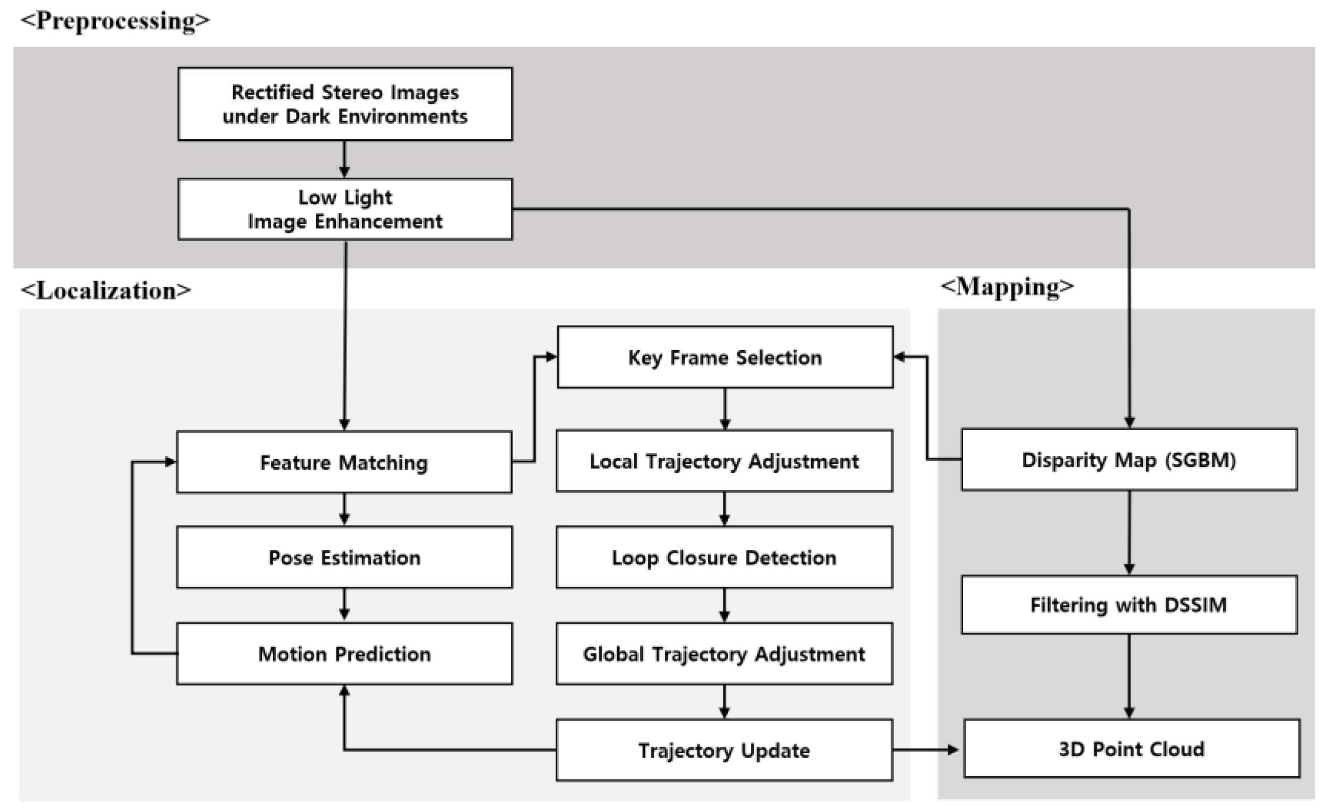
The LLIE method is categorized as a conventional deep-learning-based method. Conventional methods generally build models that characterize intensity values in a given image, refining illumination to enhance the image. Histogram Equalization (HE) improves the global contrast of an image by redistributing the histogram evenly across the intensity range. A contrast-limited adaptive histogram (CLAHE) was proposed to overcome the limitation of HE of overamplifying noise, especially in areas with low contrast [43]. The entire image is divided into overlapping patches, and HE, which is adapted to each patch, is then independently applied with a predefined threshold. The divided images tend to improve the overall quality of an image. Dehazing was developed to mitigate the haze effect in images [44]. However, when a low-light image is inverted, the visual effect is similar to that of a daytime image in fog. Therefore, a transmission map using a dark channel is first used to process the inverted low-light images. The re-inverted image offer improved brightness and enhanced visual details.
The deep-learning-based method relies on feature extraction and a deep neural network as the architecture for representing learning of data. Retinex algorithms such as SSR [45] and MSR [46], which are inspired by the human visual system, enhance the image by separately adjusting illumination and reflectance components in the scene [47]. A global illumination-aware and detail-preserving network (GladNet) first uses an encoder-decoder network to estimate global illumination distribution of low-light images [48]. A convolution network is then followed to enhance the images while preserving their details through concatenation of the original low-light image. A multi-branch low-light enhancement network (MBLLEN), which consists of a feature extraction model, an enhancement module, and a fusion module, extracts and enhances feature maps at different scales [49]. These feature maps are then fused to generate an enhanced image. A Kindling the Darkness network (KinD) is a convolution network based on retinex theory [50]. An illumination network enhances low light in an image, and a reflectance network then removes degradations. These deep-learning-based LLIE methods require paired datasets of low- and normal-light images for training purposes. However, the Moon’s surface includes landforms and features that are topographically and geologically distinct from those common on the Earth. Therefore, in this research, emulated PSR terrain is utilized to examine the proposed robotic mapping method described in Section 3.

3. Methodology

The visual SLAM-based robotic mapping method is designed for building a highly detailed 3D point cloud map in the lunar PSRs. Figure 1 shows the overall flow of the proposed method consisting of three main threads: preprocessing, localization, and dense mapping. Unlike other planetary robotic missions during daytime, a low-illumination condition in the PSRs can degrade the quality of image pairs from the stereo camera mounted on a rover. Low visibility, color distortion, and increased noise can lead to erroneous rover trajectories and mapping results. Therefore, in the preprocessing thread, the LLIE method is additionally utilized to enhance mapping capabilities (Section 3.1) and visual perception and tracking (Section 3.2).

3.1. Low-Light Enhanced Image for Dense Mapping

In the mapping thread, semi-global block matching (SGBM) [51], which involves an enhanced image pair from the preprocessing thread, is used to create a disparity map for dense 3D mapping (Figure 1). However, the enhanced images inevitably have color alterations and information loss, which can be considered as potential error sources that create noise in a 3D point cloud. Thus, structural dissimilarity (DSSIM), which is a distance metric derived from the structural similarity index measure (SSIM) [52], is used as a filter to examine a pixel-wise correspondence between stereo pairs and to increase the mapping accuracy (1):
DSSIM = 1 SSIM ( x , y ) 2
where x and y are patches extracted from the left and right images, respectively, with a kernel size of 15. A disparity estimate below the predefined DSSIM is used to create a 3D point cloud as follows:
X 3 D Y 3 D Z 3 D = K 1 X 2 D Z 3 D Y 2 D Z 3 D Z 3 D
Z 3 D = f b D ( x 2 d , y 2 d )
where K, f, and b are the intrinsic matrix, the focal length, and the baseline between two cameras, respectively. D(x2d, y2d) is the disparity estimate at 2D coordinates (x2d, y2d). Also, since the accuracy of a disparity estimate is lower at longer distances, only 3D points closer than a predefined distance (e.g., 5 m) are mapped. In the mapping process, all point clouds from every key frame are re-projected onto a coordinate system from the first frame in an image sequence. The mapping space is divided into a set of 3D grids with a predefined resolution. Each grid referenced in a 3D coordinate system registers a number of 3D points and their RGB pixel color information. The 3D grid helps in filtering and managing point clouds. For example, when the minimal number constraint of points is set as 10 in a grid size of 5 × 5 × 5 cm3, grids with numbers of points below the predefined threshold are considered as noisy measurements to filter out, and other grids are recorded as unoccupied. The RGB color associated with an occupied grid is computed simply as the mean RGB. The occupancy and color information for each 3D grid are used to maintain consistent RGB color information for the 3D point clouds.

3.2. Low-Light Enhanced Image for Localization

The localization thread adopts stereo parallel tracking and mapping (S-PTAM) [53] as a base framework for estimating a camera’s pose and trajectory by matching the correspondences between a terrain feature and identical features on the stereo image keyframe (Figure 1). The following keyframe, which is selected if the number of feature matches is less than 90% of that in the previous keyframe, is used to update the camera pose by triangulating between feature matches of neighboring frames. Although low-light enhanced images from the preprocessing thread can increase the quality and quantity of feature matches [54], the feature extraction and matching method is limited to homogeneous (textureless) terrains in the PSRs. Therefore, in addition to the nearest neighbor distance ratio (NNDR), the disparity map based on the mapping thread is used as another constraint to increase accurate feature matches. In a sequence of stereo image pairs, the nearest neighbor feature matches are typically obtained by searching along the epipolar line. The disparity between feature matches is then computed and compared with the corresponding position on the disparity map. When the difference between two disparities is below a threshold, the feature matches are considered to be valid. Also, the locational error is unavoidably propagated and consequently accumulated into the camera trajectory while a rover is traversing rugged and homogeneous terrains. The bundle adjustment, which involves a series of keyframes from the beginning, is used to locally optimize the camera poses. Also, when a rover returns to a previously visited place, loop closure using a Bag of Words (BoW) model [55] is used to globally minimize the accumulated drift along the rover’s trajectory.

4. Application and Results

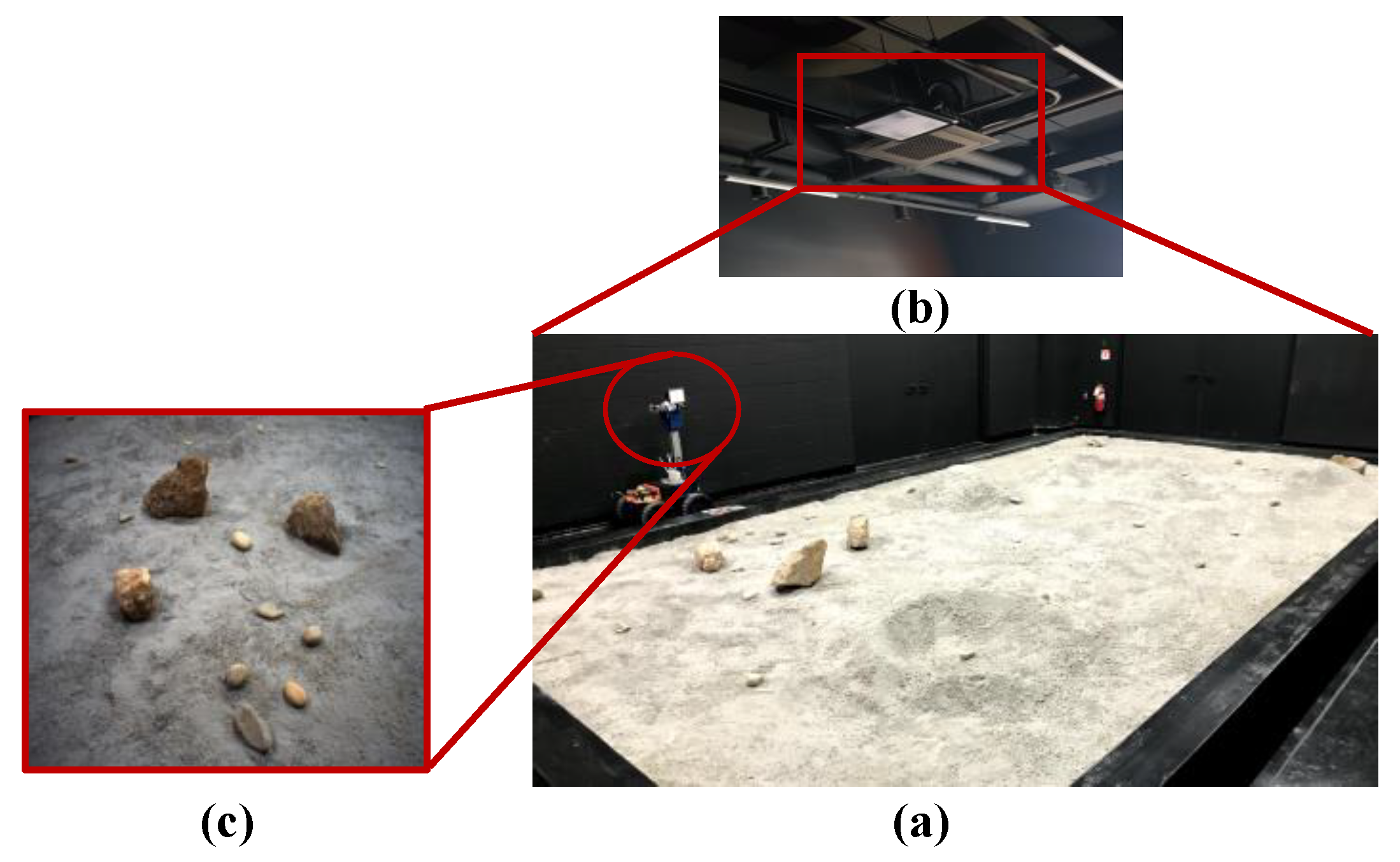
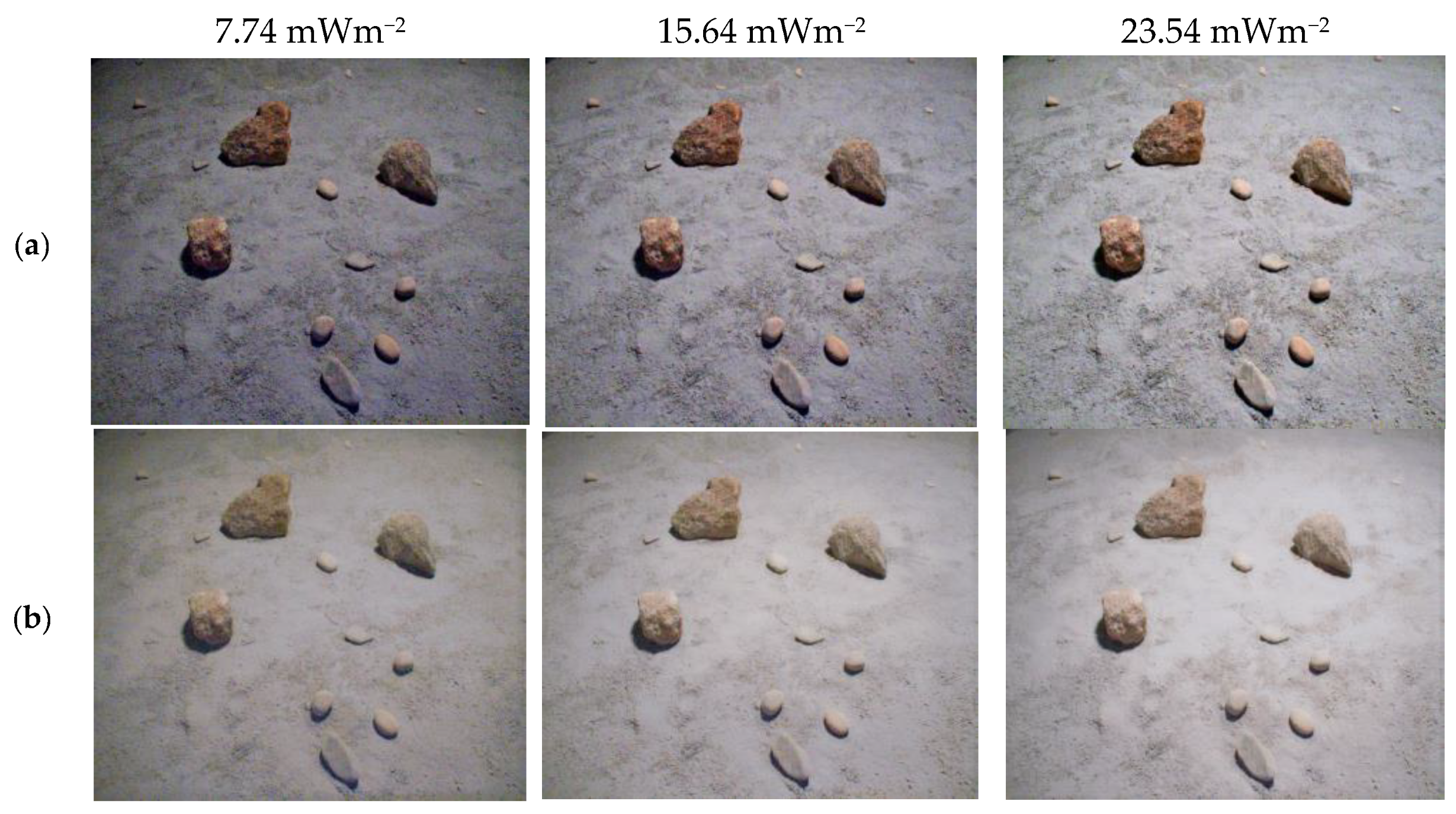
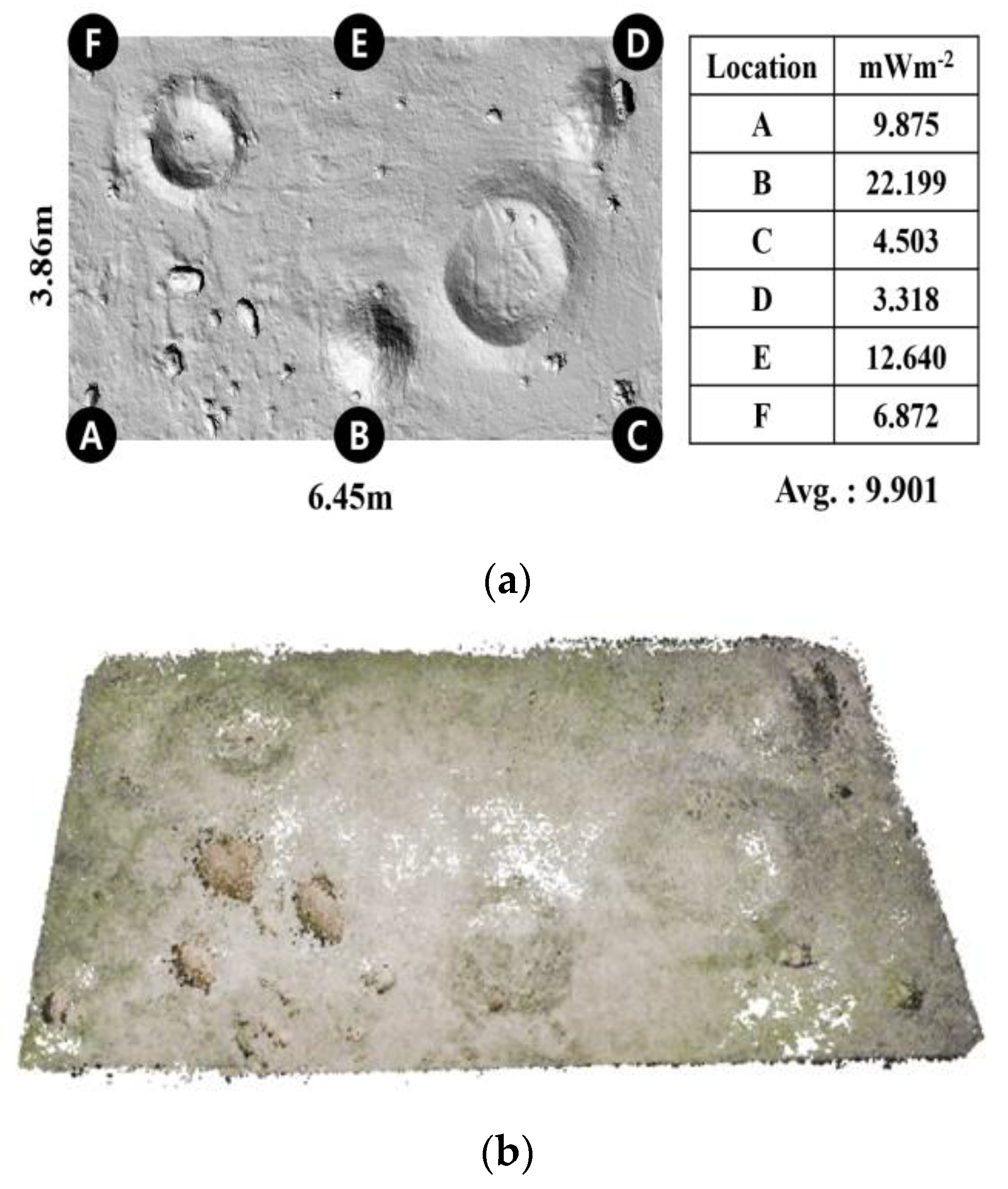
4.1. Test Environment

The robotic mapping approach in the previous section was applied to the emulated lunar terrain (hereafter referred to as the testbed) at the Korea Institute of Civil Engineering and Building Technology. The test bed, which consists of a soil bin (Figure 2a) and an adjustable-light-level LED lamp (Figure 2b), was designed to allow the rover to simulate the mapping process under dark environments of PSRs. The soil bin has horizontal dimensions of 6.45 m × 3.86 m. Soil is used to shape small craters and rounded piles on the flat ground, to which a layer of the lunar simulant (KLS-1) [56] is added, and rocks and pebbles are irregularly placed to emulate various terrain features on the lunar surface. The LED lamp, covered with diffuser films, is utilized for simulating sunlight. The rover is a four wheeled mobile platform equipped with two cameras (FLIR Blackfly) at a 20 cm baseline (Figure 2c). In the experiments, the camera parameters were automatically adjusted using FLIR SpinView. Gain, gamma, and exposure time were fixed at 17.9 db, 0.7, and 49,991 μs, respectively. Also, during rover movement terrain images were collected at a frame rate of 15 frames per second (fps). CLAHE and Dehaze were selected as representative conventional LLIE methods. Due to the absence of on-site images of the lunar PSRs, it would not be feasible to develop a new deep-learning-based LLIE method. Therefore, well-known LLIE methods like GladNet, KIND, and MBLLEN were selected based on preliminary experiments using outdoor images at sunset. The deep-learning-based LLIE methods were trained with the Low-Light (LOL) dataset, which contains 500 low-light and normal-light image pairs [57]. These methods were further fine-tuned with 400 image sets from emulated illumination conditions in the testbed. In the experiment, the LLIE methods were empirically applied to the test image set under varying illumination conditions from 0.008 mWm−2 to 0.025 mWm−2 (Figure 3), which were then compared to the images taken in a normal light condition (Figure 2c).

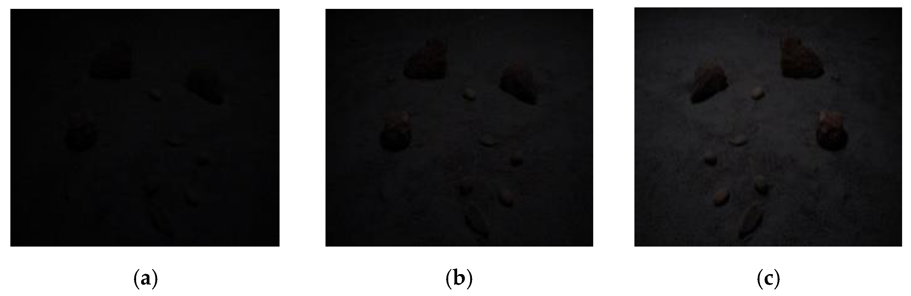
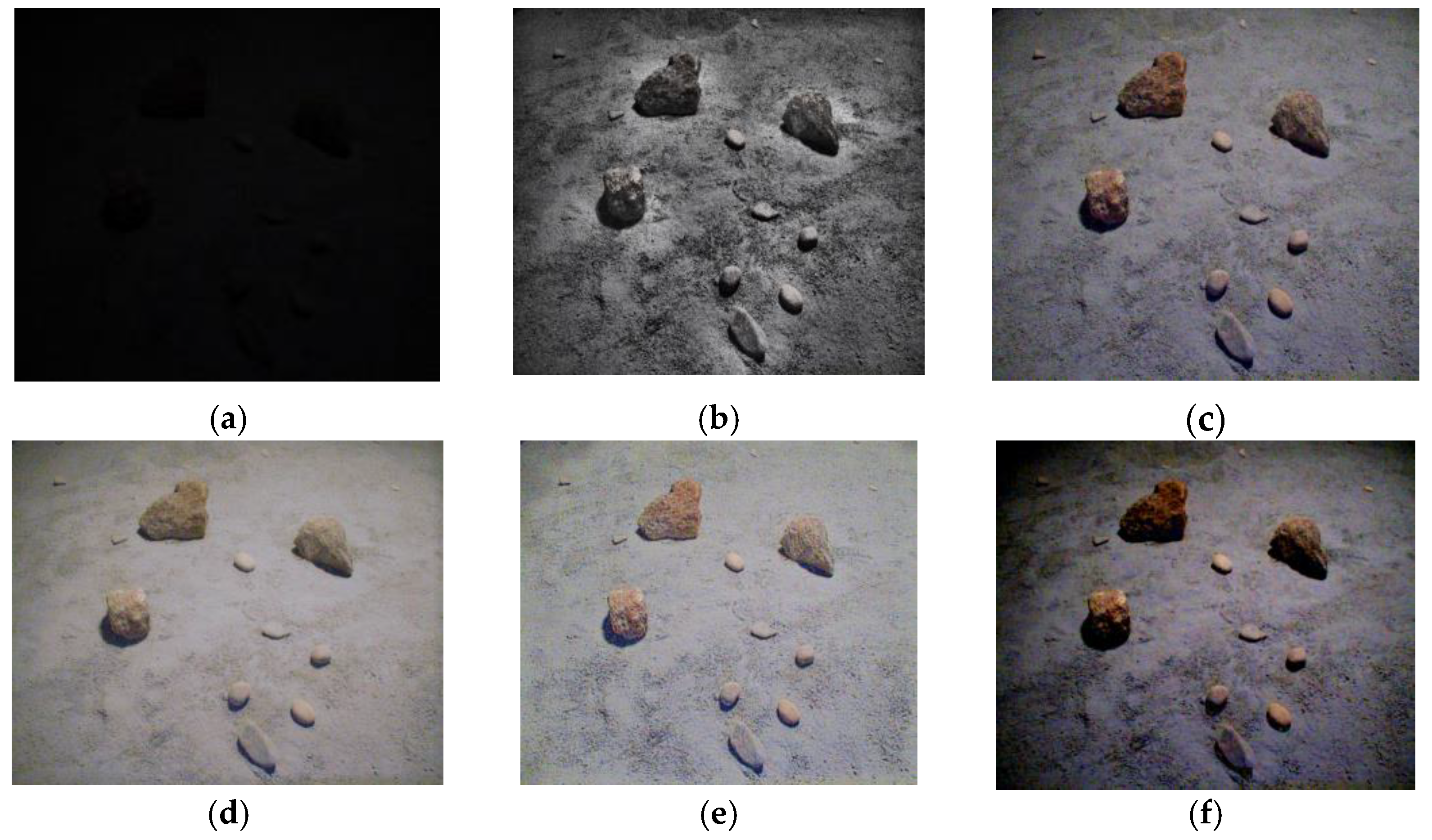
4.2. Experiments under Dark Illumination Conditions

The first experiment was designed to examine the image enhancement results from the darkest illumination condition in the test image set. Terrain images in Figure 2c and Figure 3a were taken at the same pose and orientation of the rover-mounted camera but under normal (1896 mWm−2) and low (7.74 mWm−2) lighting conditions. The enhanced images were then quantitatively and qualitatively inspected.
Peak Signal-to-Noise Ratio (PSNR), Structural Similarity Index Map (SSIM) [58], and Delta-E were used to quantify the enhanced image qualities, using the normal light image as the reference image. PSNR is the ratio of the maximum value of the pixel to the noise. A higher PSNR value implies that a better dark image has been restored to match the normal light image. SSIM analyzes the similarity of brightness, contrast, and structural changes within an image pair in terms of human perception. A SSIM value closer to 1 means that the enhanced image is visually similar to the normal light image, preserving the identical structure. Delta-E is a color difference measure between normal-light and enhanced images. In contrast to PNSR and SSIM, a lower value indicates that it is harder for humans to distinguish between the colors in two images. In Table 1, the evaluation metrics of PSNR, SSIM, Delta-E indicate that all LLIE methods significantly improve the perceptual quality of the low-light image. The overall performance of GladNet is obviously better than the others. However, the enhanced images are inconsistently evaluated because each metric treats different aspects of image quality. For example, Dehaze and KIND achieve the second and third best measures in PSNR and Delta-E, respectively, but for SSIM, KIND slightly outperforms Dehaze.
Quantitative measures do not always correspond to subjective human perceptions of image quality. For example, the visual inspection shown in Figure 4 confirms that hidden terrain objects (e.g., rocks and pebbles) in the dark (Figure 4a) are visualized with improved brightness. However, in Figure 4b, CLAHE causes severe chromatic distortion, resulting in an abnormal appearance. In MBLLEN (Figure 4f), the terrain objects and details are made distinct by the improved color and contrast, but an excessive vignetting effect degrades the image quality. In Figure 4e, KIND preserves the clarity, but chromatic artifacts, mainly blue, are randomly introduced over the entire image. Dehaze (Figure 4c) improves the color and contrast without severely degrading the image quality, but the color of the entire image deviates from that of the normal light image. GladNet, in Figure 4d, improves the brightness best, maintaining clarity and color in the darkest condition illustrated in Figure 3a.
Although the PSRs are known to have low-light environments, the lighting condition varies depending on the landforms and topological features. Therefore, we devised a second experiment to investigate the consistency of restoration in various illumination conditions. Dehaze and GladNet were selected due to their stable quantitative and qualitative performance in the first experiment. Figure 5 shows the image enhancement results for the low-light images in Figure 3. In Figure 5a, the image brightness of Dehaze is obviously proportional to the illumination level. However, in Figure 5b, GladNet tends to demonstrate relatively consistent color enhancements of ground and terrain objects, maintaining image quality. In addition, when enhanced images in 7.74 mWm−2 and 23.54 mWm−2 are compared, GladNet enhances low-light images with less noise. For this reason, we ultimately selected GladNet for the proposed robotic mapping method to reconstruct the emulated terrain in the test bed.

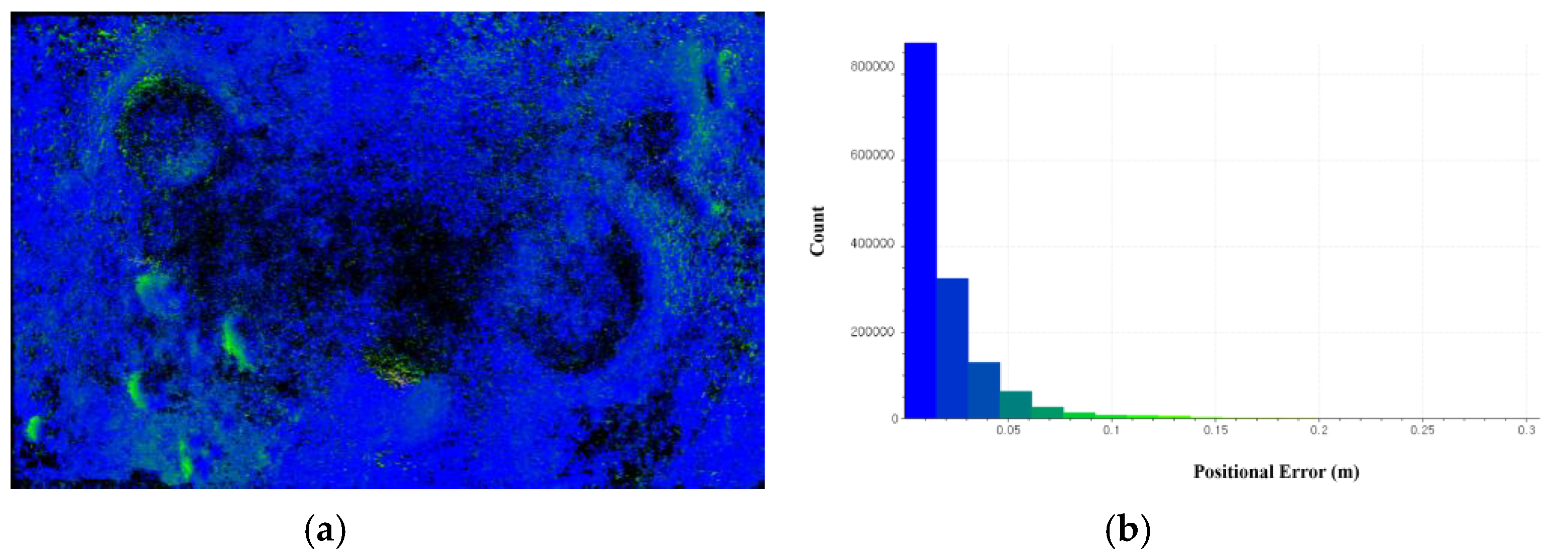
4.3. 3D Mapping Results

In the experiment for 3D mapping, the rover moved along a clockwise path around the soil bin and returned to its starting position. In the test bed, the LED lamp on the ceiling is not located at the center above the soil bin. The six locations from A to F show different illumination measures varying from 3.318 mWm−2 to 22.199 mWm−2 (Figure 6a). Under such dark conditions, without LLIE methods the proposed method failed to reconstruct a 3D terrain due to the insufficient number of feature matches. However, when combined with GladNet, the proposed method sequentially enhanced the stereo image pairs from the rover-mounted camera, resulting in a significant improvement in both quantity and quality of feature matches. Moreover, the restored color information combined with the depth value in the disparity map produced point clouds with consistent brightness and color (Figure 6b). The point cloud map has sparse density in the middle, and occlusions exist at nearby craters and rocks due to the low tilting angle of the stereo camera mounted on the rover’s mast. However, the colorized 3D points enable an enhanced understanding of morphological characteristics such as craters and mounds. Furthermore, rocks and pebbles with different colors are clearly identified, along with their respective sizes and shapes.
Also, for the accuracy assessment, the referenced point cloud from the 3D laser scanner (Trimble X7) was compared to the 3D point clouds from the proposed method. The Iterative Closest Point (ICP) method was employed to align the two sets of point clouds, and the Root Mean Square Error (RMSE) measure was then computed as 0.034 m. Meanwhile, the positional error distribution over the test bed (Figure 7a) was computed along with the positional error histogram (Figure 7b), using identical magnitude of a positional error ranging from blue to yellow-green. The RMSE measure and the positional error distribution provide a good indication of the overall performance of the proposed method, demonstrating its ability to obtain accurate and reliable point clouds in low illumination conditions. The positional error histogram also confirms that 85% of positional errors are less than 0.03 m.

5. Discussion and Conclusions

The discovery of water ice in the lunar PSRs has greatly increased their scientific importance and interest, leading to new plans for a robotic exploration mission to collect data on the distribution and abundance of water ice and other volatile compounds in the lunar soil. Although the PSRs are exposed to sunlight or starlight reflected diffusely from adjacent sunlit regions, the low illumination poses technical challenges for robotic mapping due to the restricted visibility range and the accumulation of errors over long-term operations. Although artificial lights could be helpful for the robotic mapping, uneven illumination and shadows nearby terrain features may have adverse effects on rover trajectory estimation and mapping results.
This research presents a robotic mapping method that leverages the LLIE method to improve the brightness and color of low-light terrain images. However, the lighting conditions in the PSRs can vary depending on the landforms and topological features. Therefore, in the experiment, three terrain images under different illumination conditions were obtained from an emulated PSR terrain. The performance of both conventional (CLAHE, Dehaze) and deep-learning-based (GladNet, KinD, MBLLEN) LLIE methods was evaluated to ensure image enhancement results in the darkest conditions as well as consistent color restoration across terrain images at different degrees of illumination. The experimental results demonstrated that all LLIE methods reveal hidden details and outlines of terrain objects in low-light images. However, the predefined mathematical models in the conventional methods have limitations in scalability for diverse low-lighting conditions. The excessive contrast enhancement in the CLAHE leads to the amplification of image details and intensity beyond the desired level. Although Dehaze enhances both color and contrast without significant degradation of image quality, the brightness of enhanced images varies depending on the illumination level. In contrast, the deep-learning-based methods are data-driven, requiring a paired training dataset to derive a learning process to find unknown structures or patterns in diverse illumination environments. In particular, GladNet significantly improves image quality metrics and flexibly enhances structural consistency, brightness, and color consistency of low-light images. In the experiment for 3D mapping, the proposed method without LLIE methods failed to reconstruct a 3D terrain. However, when combined with GladNet, the dense point cloud map was reconstructed with a more accurate natural appearance and inherent colors.
The experimental results show that the proposed method has potential for the robotic exploration of the lunar PSRs. However, since robotic exploration of the lunar PSRs has not yet been achieved, there are no direct measurements of illumination available. It is expected that the actual illuminance levels will vary significantly depending on factors such as topography, nearby terrain features, and the specific location within the lunar PSRs. Also, the illumination and terrain conditions in the testbed are limited to emulate the large-scale and complex environment of the PSRs. Therefore, as the knowledge of the lunar PSRs advances, the proposed method should be continually improved.

Author Contributions

Conceptualization, S.H.; methodology, S.H. and J.-M.P.; validation, J.-M.P.; formal analysis, S.H. and J.-M.P.; resources, H.-S.S.; data curation, J.-M.P. and S.H.; writing—original draft preparation, S.H.; writing—review and editing, S.H. and J.-M.P.; project administration, H.-S.S.; funding acquisition, H.-S.S. All authors have read and agreed to the published version of the manuscript.

Funding

This work is supported in part by “Development of environmental simulator and advanced construction technologies over TRL6 in extreme conditions” funded by the Korea Institute of Civil Engineering and Building Technology, in part by a National Research Foundation of Korea Grant funded by the Korean Government (NRF-2022R1F1A1064577), and in part by an Inha University research grant.

Data Availability Statement

Not applicable.

Conflicts of Interest

The authors declare no conflict of interest.

References

  1. ISECG. Global Exploration Roadmap: Lunar Surface Exploration Scenario Update. 2020. Available online: https://www.globalspaceexploration.org/?p=1049 (accessed on 10 April 2023).
  2. Colaprete, A.; Elphic, R.; Shirley, M.; Ennico Smith, K.; Lim, D.; Siegler, M.; Mirmalek, Z.; Zacny, K.; Janine, C. The volatiles investigating polar exploration rover (VIPER) mission: Measurement goals and traverse planning. In Proceedings of the AGU Fall Meeting Abstracts, New Orleans, LA, USA, 13–17 December 2021; p. P53B-08. [Google Scholar]
  3. Smith, M.; Craig, D.; Herrmann, N.; Mahoney, E.; Krezel, J.; McIntyre, N.; Goodliff, K. The Artemis program: An overview of NASA’s activities to return humans to the moon. In Proceedings of the 2020 IEEE Aerospace Conference, Big Sky, MT, USA, 7–14 March 2020; pp. 1–10. [Google Scholar]
  4. Casanova, S.; Espejel, C.; Dempster, A.G.; Anderson, R.C.; Caprarelli, G.; Saydam, S. Lunar polar water resource exploration–Examination of the lunar cold trap reservoir system model and introduction of play-based exploration (PBE) techniques. Planet. Space Sci. 2020, 180, 104742. [Google Scholar] [CrossRef]
  5. Hayne, P.O.; Hendrix, A.; Sefton-Nash, E.; Siegler, M.A.; Lucey, P.G.; Retherford, K.D.; Williams, J.-P.; Greenhagen, B.T.; Paige, D.A. Evidence for exposed water ice in the Moon’s south polar regions from Lunar Reconnaissance Orbiter ultraviolet albedo and temperature measurements. Icarus 2015, 255, 58–69. [Google Scholar] [CrossRef]
  6. Anand, M. Lunar water: A brief review. Earth Moon Planets 2010, 107, 65–73. [Google Scholar] [CrossRef]
  7. Anand, M.; Crawford, I.A.; Balat-Pichelin, M.; Abanades, S.; Van Westrenen, W.; Péraudeau, G.; Jaumann, R.; Seboldt, W. A brief review of chemical and mineralogical resources on the Moon and likely initial in situ resource utilization (ISRU) applications. Planet. Space Sci. 2012, 74, 42–48. [Google Scholar] [CrossRef]
  8. Schlüter, L.; Cowley, A. Review of techniques for In-Situ oxygen extraction on the moon. Planet. Space Sci. 2020, 181, 104753. [Google Scholar] [CrossRef]
  9. Lemelin, M.; Li, S.; Mazarico, E.; Siegler, M.A.; Kring, D.A.; Paige, D.A. Framework for coordinated efforts in the exploration of volatiles in the south polar region of the moon. Planet. Sci. J. 2021, 2, 103. [Google Scholar] [CrossRef]
  10. Bickel, V.T.; Moseley, B.; Lopez-Francos, I.; Shirley, M. Peering into lunar permanently shadowed regions with deep learning. Nat. Commun. 2021, 12, 5607. [Google Scholar] [CrossRef]
  11. Rew, D.-Y.; Ju, G.-H.; Kang, S.-W.; Lee, S.-R. Conceptual design of Korea Aerospace Research Institute lunar explorer dynamic simulator. J. Astron. Space Sci. 2010, 27, 377–382. [Google Scholar] [CrossRef] [Green Version]
  12. Austin, A.; Sherwood, B.; Elliott, J.; Colaprete, A.; Zacny, K.; Metzger, P.; Sims, M.; Schmitt, H.; Magnus, S.; Fong, T. Robotic lunar surface operations 2. Acta Astronaut. 2020, 176, 424–437. [Google Scholar] [CrossRef]
  13. Hong, S.; Bangunharcana, A.; Park, J.-M.; Choi, M.; Shin, H.-S. Visual SLAM-based robotic mapping method for planetary construction. Sensors 2021, 21, 7715. [Google Scholar] [CrossRef]
  14. Cahill, S.A. Lunar Terrain Vehicle (LTV): Center Capabilities: Silicon Valley NASA Ames Research Center; INASA Ames Research Center: Mountain View, CA, USA, 2021. [Google Scholar]
  15. Tong, C.H.; Barfoot, T.D.; Dupuis, É. Three-dimensional SLAM for mapping planetary work site environments. J. Field Robot. 2012, 29, 381–412. [Google Scholar] [CrossRef]
  16. Schuster, M.J.; Brunner, S.G.; Bussmann, K.; Büttner, S.; Dömel, A.; Hellerer, M.; Lehner, H.; Lehner, P.; Porges, O.; Reill, J. Towards autonomous planetary exploration. J. Intell. Robot. Syst. 2019, 93, 461–494. [Google Scholar] [CrossRef] [Green Version]
  17. Ip, W.-H.; Yan, J.; Li, C.-L.; Ouyang, Z.-Y. Preface: The Chang’e-3 lander and rover mission to the Moon. Res. Astron. Astrophys. 2014, 14, 1511. [Google Scholar] [CrossRef]
  18. Li, C.; Zuo, W.; Wen, W.; Zeng, X.; Gao, X.; Liu, Y.; Fu, Q.; Zhang, Z.; Su, Y.; Ren, X. Overview of the Chang’e-4 mission: Opening the frontier of scientific exploration of the lunar far side. Space Sci. Rev. 2021, 217, 35. [Google Scholar] [CrossRef]
  19. Bajracharya, M.; Maimone, M.W.; Helmick, D. Autonomy for mars rovers: Past, present, and future. Computer 2008, 41, 44–50. [Google Scholar] [CrossRef] [Green Version]
  20. Smith, K.E.; Colaprete, A.; Lim, D.; Andrews, D. The VIPER Mission, a Resource-Mapping Mission on Another Celestial Body. In Proceedings of the SRR XXII MEETING Colorado School of Mines, Golden, CO, USA, 7–10 June 2022. [Google Scholar]
  21. Kloos, J.L.; Moores, J.E.; Godin, P.J.; Cloutis, E. Illumination conditions within permanently shadowed regions at the lunar poles: Implications for in-situ passive remote sensing. Acta Astronaut. 2021, 178, 432–451. [Google Scholar] [CrossRef]
  22. Mahanti, P.; Thompson, T.J.; Robinson, M.S.; Humm, D.C. View Factor-Based Computation of Secondary Illumination Within Lunar Permanently Shadowed Regions. IEEE Geosci. Remote Sens. Lett. 2022, 19, 8027004. [Google Scholar] [CrossRef]
  23. Mazarico, E.; Neumann, G.; Smith, D.; Zuber, M.; Torrence, M. Illumination conditions of the lunar polar regions using LOLA topography. Icarus 2011, 211, 1066–1081. [Google Scholar] [CrossRef]
  24. Gläser, P.; Oberst, J.; Neumann, G.; Mazarico, E.; Speyerer, E.; Robinson, M. Illumination conditions at the lunar poles: Implications for future exploration. Planet. Space Sci. 2018, 162, 170–178. [Google Scholar] [CrossRef] [Green Version]
  25. Wei, G.; Li, X.; Zhang, W.; Tian, Y.; Jiang, S.; Wang, C.; Ma, J. Illumination conditions near the Moon’s south pole: Implication for a concept design of China’s Chang’E− 7 lunar polar exploration. Acta Astronaut. 2023, 208, 74–81. [Google Scholar] [CrossRef]
  26. Arizona State University. ShadowCam. Available online: http://shadowcam.sese.asu.edu/ (accessed on 1 April 2023).
  27. Brown, H.; Boyd, A.; Denevi, B.; Henriksen, M.; Manheim, M.; Robinson, M.; Speyerer, E.; Wagner, R. Resource potential of lunar permanently shadowed regions. Icarus 2022, 377, 114874. [Google Scholar] [CrossRef]
  28. Golombek, M.; Anderson, R.; Barnes, J.R.; Bell III, J.; Bridges, N.; Britt, D.; Brückner, J.; Cook, R.; Crisp, D.; Crisp, J. Overview of the Mars Pathfinder Mission: Launch through landing, surface operations, data sets, and science results. J. Geophys. Res. Planets 1999, 104, 8523–8553. [Google Scholar] [CrossRef] [Green Version]
  29. Maimone, M.; Cheng, Y.; Matthies, L. Two years of visual odometry on the mars exploration rovers. J. Field Robot. 2007, 24, 169–186. [Google Scholar] [CrossRef] [Green Version]
  30. Rankin, A.; Maimone, M.; Biesiadecki, J.; Patel, N.; Levine, D.; Toupet, O. Driving curiosity: Mars rover mobility trends during the first seven years. In Proceedings of the 2020 IEEE Aerospace Conference, Big Sky, MT, USA, 7–14 March 2020; pp. 1–19. [Google Scholar]
  31. Di, K.; Liu, Z.; Wan, W.; Peng, M.; Liu, B.; Wang, Y.; Gou, S.; Yue, Z. Geospatial technologies for Chang’e-3 and Chang’e-4 lunar rover missions. Geo-Spat. Inf. Sci. 2020, 23, 87–97. [Google Scholar] [CrossRef]
  32. Wong, C.; Yang, E.; Yan, X.-T.; Gu, D. Adaptive and intelligent navigation of autonomous planetary rovers—A survey. In Proceedings of the 2017 NASA/ESA Conference on Adaptive Hardware and Systems (AHS), Pasadena, CA, USA, 24–27 July 2017; pp. 237–244. [Google Scholar]
  33. Hidalgo-Carrió, J.; Poulakis, P.; Kirchner, F. Adaptive localization and mapping with application to planetary rovers. J. Field Robot. 2018, 35, 961–987. [Google Scholar] [CrossRef]
  34. Jia, Y.; Liu, L.; Wang, X.; Guo, N.; Wan, G. Selection of Lunar South Pole Landing Site Based on Constructing and Analyzing Fuzzy Cognitive Maps. Remote Sens. 2022, 14, 4863. [Google Scholar] [CrossRef]
  35. Bajpai, A.; Burroughes, G.; Shaukat, A.; Gao, Y. Planetary monocular simultaneous localization and mapping. J. Field Robot. 2016, 33, 229–242. [Google Scholar] [CrossRef]
  36. Tseng, K.-K.; Li, J.; Chang, Y.; Yung, K.; Chan, C.; Hsu, C.-Y. A new architecture for simultaneous localization and mapping: An application of a planetary rover. Enterp. Inf. Syst. 2019, 15, 1162–1178. [Google Scholar] [CrossRef]
  37. Peng, M.; Wan, W.; Xing, Y.; Wang, Y.; Liu, Z.; Di, K.; Zhao, Q.; Teng, B.; Mao, X. Integrating Depth and Image Sequences for Planetary Rover Mapping Using Rgb-D Sensor. Int. Arch. Photogramm. Remote Sens. Spat. Inf. Sci. 2018, 42, 1369–1374. [Google Scholar] [CrossRef] [Green Version]
  38. Di, K.; Zhao, Q.; Wan, W.; Wang, Y.; Gao, Y. RGB-D SLAM based on extended bundle adjustment with 2D and 3D information. Sensors 2016, 16, 1285. [Google Scholar] [CrossRef] [Green Version]
  39. Xiao, L.; Zhu, P.; Fang, G.; Xiao, Z.; Zou, Y.; Zhao, J.; Zhao, N.; Yuan, Y.; Qiao, L.; Zhang, X. A young multilayered terrane of the northern Mare Imbrium revealed by Chang’E-3 mission. Science 2015, 347, 1226–1229. [Google Scholar] [CrossRef] [PubMed]
  40. Di, K.; Zhu, M.H.; Yue, Z.; Lin, Y.; Wan, W.; Liu, Z.; Gou, S.; Liu, B.; Peng, M.; Wang, Y. Topographic evolution of Von Kármán crater revealed by the lunar rover Yutu-2. Geophys. Res. Lett. 2019, 46, 12764–12770. [Google Scholar] [CrossRef]
  41. Kwan, C.; Chou, B.; Ayhan, B. Enhancing Stereo Image Formation and Depth Map Estimation for Mastcam Images. In Proceedings of the 2018 9th IEEE Annual Ubiquitous Computing, Electronics & Mobile Communication Conference (UEMCON), New York, NY, USA, 8–10 November 2018; pp. 566–572. [Google Scholar]
  42. Maki, J.; Gruel, D.; McKinney, C.; Ravine, M.; Morales, M.; Lee, D.; Willson, R.; Copley-Woods, D.; Valvo, M.; Goodsall, T. The Mars 2020 Engineering Cameras and Microphone on the Perseverance Rover: A Next-Generation Imaging System for Mars Exploration. Space Sci. Rev. 2020, 216, 137. [Google Scholar] [CrossRef]
  43. Zuiderveld, K. Contrast limited adaptive histogram equalization. In Graphics Gems IV; Heckbert, P., Ed.; Academic Press: San Diego, CA, USA, 1994; pp. 474–485. [Google Scholar]
  44. He, K.; Sun, J.; Tang, X. Single image haze removal using dark channel prior. IEEE Trans. Pattern Anal. Mach. Intell. 2010, 33, 2341–2353. [Google Scholar] [PubMed]
  45. Jobson, D.J.; Rahman, Z.; Woodell, G.A. Properties and performance of a center/surround retinex. IEEE Trans. Image Process. 1997, 6, 451–462. [Google Scholar] [CrossRef] [PubMed]
  46. Jobson, D.J.; Rahman, Z.; Woodell, G.A. A multiscale retinex for bridging the gap between color images and the human observation of scenes. IEEE Trans. Image Process. 1997, 6, 965–976. [Google Scholar] [CrossRef] [Green Version]
  47. Land, E.H. The retinex theory of color vision. Sci. Am. 1977, 237, 108–129. [Google Scholar] [CrossRef]
  48. Wang, W.; Wei, C.; Yang, W.; Liu, J. Gladnet: Low-light enhancement network with global awareness. In Proceedings of the 2018 13th IEEE International Conference on Automatic Face & Gesture Recognition (FG 2018), Xi’an, China, 15–19 May 2018; pp. 751–755. [Google Scholar]
  49. Lv, F.; Lu, F.; Wu, J.; Lim, C. MBLLEN: Low-Light Image/Video Enhancement Using CNNs. In Proceedings of the BMVC, Newcastle, UK, 3–6 September 2018; p. 4. [Google Scholar]
  50. Zhang, Y.; Zhang, J.; Guo, X. Kindling the darkness: A practical low-light image enhancer. In Proceedings of the 27th ACM International Conference on Multimedia, Nice, France, 21–25 October 2019; pp. 1632–1640. [Google Scholar]
  51. Hirschmuller, H. Stereo processing by semiglobal matching and mutual information. IEEE Trans. Pattern Anal. Mach. Intell. 2007, 30, 328–341. [Google Scholar] [CrossRef]
  52. Loza, A.; Mihaylova, L.; Canagarajah, N.; Bull, D. Structural similarity-based object tracking in video sequences. In Proceedings of the 2006 9th International Conference on Information Fusion, Florence, Italy, 10–13 July 2006; pp. 1–6. [Google Scholar]
  53. Pire, T.; Fischer, T.; Castro, G.; De Cristóforis, P.; Civera, J.; Berlles, J.J. S-PTAM: Stereo parallel tracking and mapping. Robot. Auton. Syst. 2017, 93, 27–42. [Google Scholar] [CrossRef] [Green Version]
  54. Park, J.-M.; Hong, S.; Shin, H.-S. Experiment on Low Light Image Enhancement and Feature Extraction Methods for Rover Exploration in Lunar Permanently Shadowed Region. KSCE J. Civ. Environ. Eng. Res. 2022, 42, 741–749. [Google Scholar]
  55. Gálvez-López, D.; Tardos, J.D. Bags of binary words for fast place recognition in image sequences. IEEE Trans. Robot. 2012, 28, 1188–1197. [Google Scholar] [CrossRef]
  56. Ryu, B.-H.; Wang, C.-C.; Chang, I. Development and geotechnical engineering properties of KLS-1 lunar simulant. J. Aerosp. Eng. 2018, 31, 04017083. [Google Scholar] [CrossRef] [Green Version]
  57. Wei, C.; Wang, W.; Yang, W.; Liu, J. Deep retinex decomposition for low-light enhancement. arXiv 2018, arXiv:1808.04560. [Google Scholar]
  58. Wang, Z.; Bovik, A.C.; Sheikh, H.R.; Simoncelli, E.P. Image quality assessment: From error visibility to structural similarity. IEEE Trans. Image Process. 2004, 13, 600–612. [Google Scholar] [CrossRef] [Green Version]
Figure 1. Overall flow of the robotic mapping method.
Remotesensing 15 03412 g001
Figure 2. Emulated lunar terrain (Test bed): (a) soil bin layered with a lunar simulant (KLS-1), (b) adjustable-light-level LED lamp, (c) terrain image in a normal light condition.
Remotesensing 15 03412 g002
Figure 3. Test image set under varying illumination conditions: (a) 7.74 mWm−2, (b) 15.64 mWm−2, (c) 23.54 mWm−2.
Remotesensing 15 03412 g003
Figure 4. Low-light image and image enhancement results under 7.74 mWm−2: (a) low-light image, (b) CLAHE, (c) Dehaze, (d) GladNet, (e) KIND, (f) MBLLEN.
Remotesensing 15 03412 g004
Figure 5. Image enhancement results under different degrees of low illumination: (a) Dehaze, (b) GladNet.
Remotesensing 15 03412 g005
Figure 6. Robotic mapping results in the test bed: (a) test bed with illumination conditions, (b) 3D point cloud mapping results.
Remotesensing 15 03412 g006
Figure 7. Accuracy assessment (identical color index is used to represent a magnitude of positional errors in both sub-figures): (a) positional error distribution map; (b) positional error histogram.
Remotesensing 15 03412 g007
Table 1. Performance of LLIE Methods on Low-Light Image.
LLIEPSNR (dB)SSIMDelta-E
Low-Light Image7.480.1645.68
CLAHE14.860.2917.57
Dehaze19.120.3616.61
GladNet19.700.4512.38
KIND16.590.3817.41
MBLLEN14.960.3822.14
Disclaimer/Publisher’s Note: The statements, opinions and data contained in all publications are solely those of the individual author(s) and contributor(s) and not of MDPI and/or the editor(s). MDPI and/or the editor(s) disclaim responsibility for any injury to people or property resulting from any ideas, methods, instructions or products referred to in the content.

