
Performance of BDS B1 Frequency Standard Point Positioning during the Main Phase of Different Classified Geomagnetic Storms in China and the Surrounding Area

Abstract
:1. Introduction
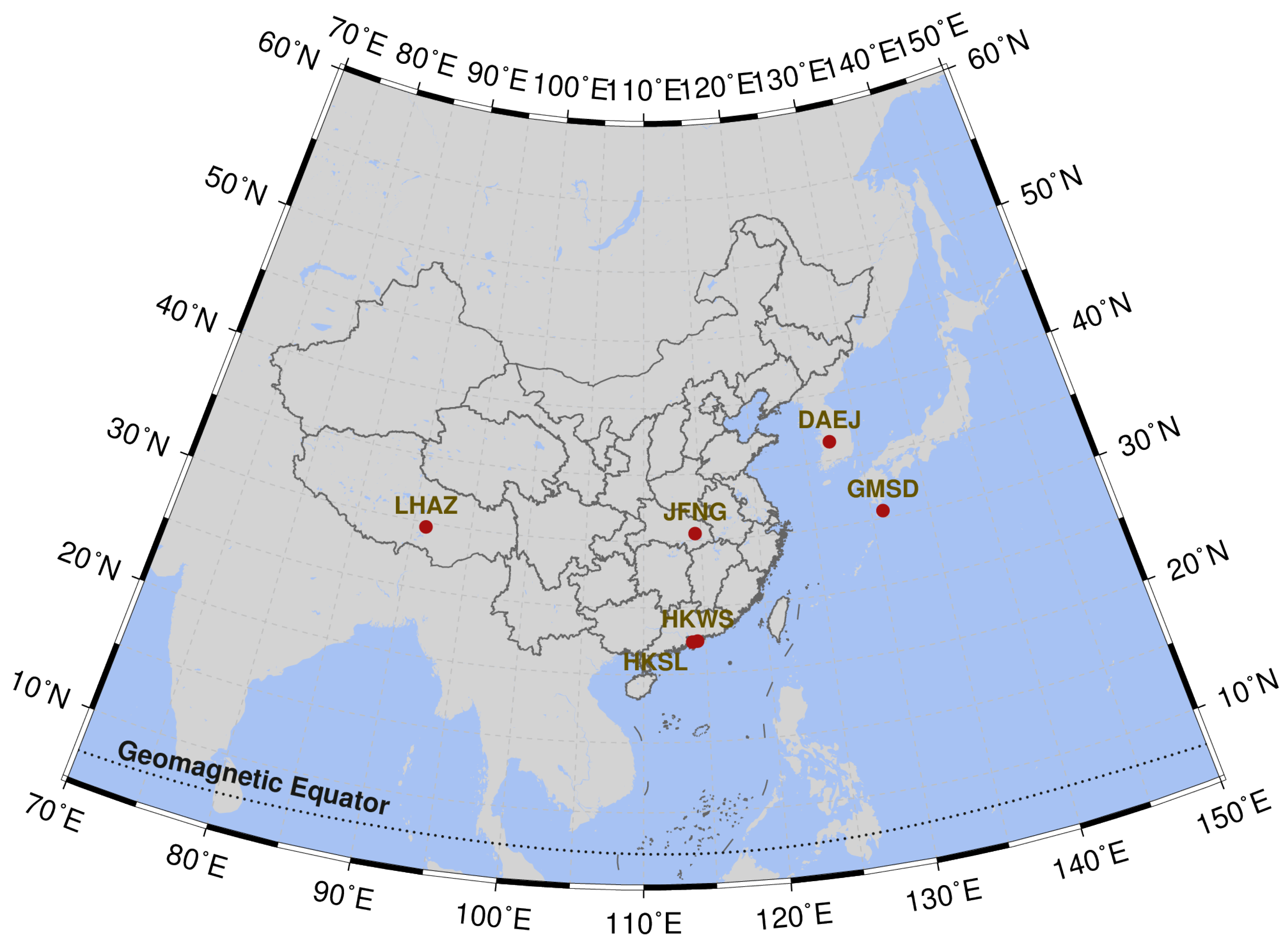
2. Methodology
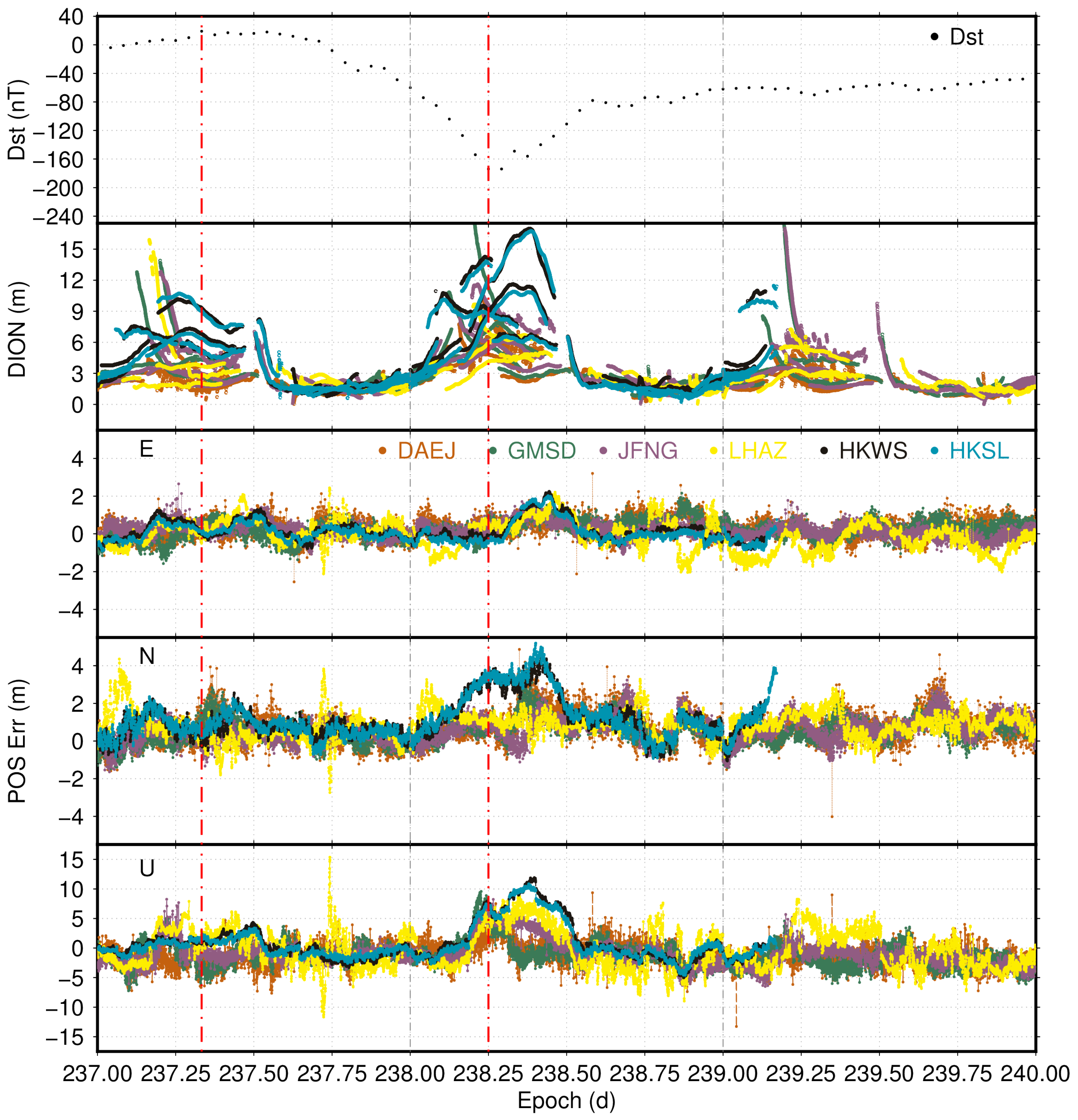
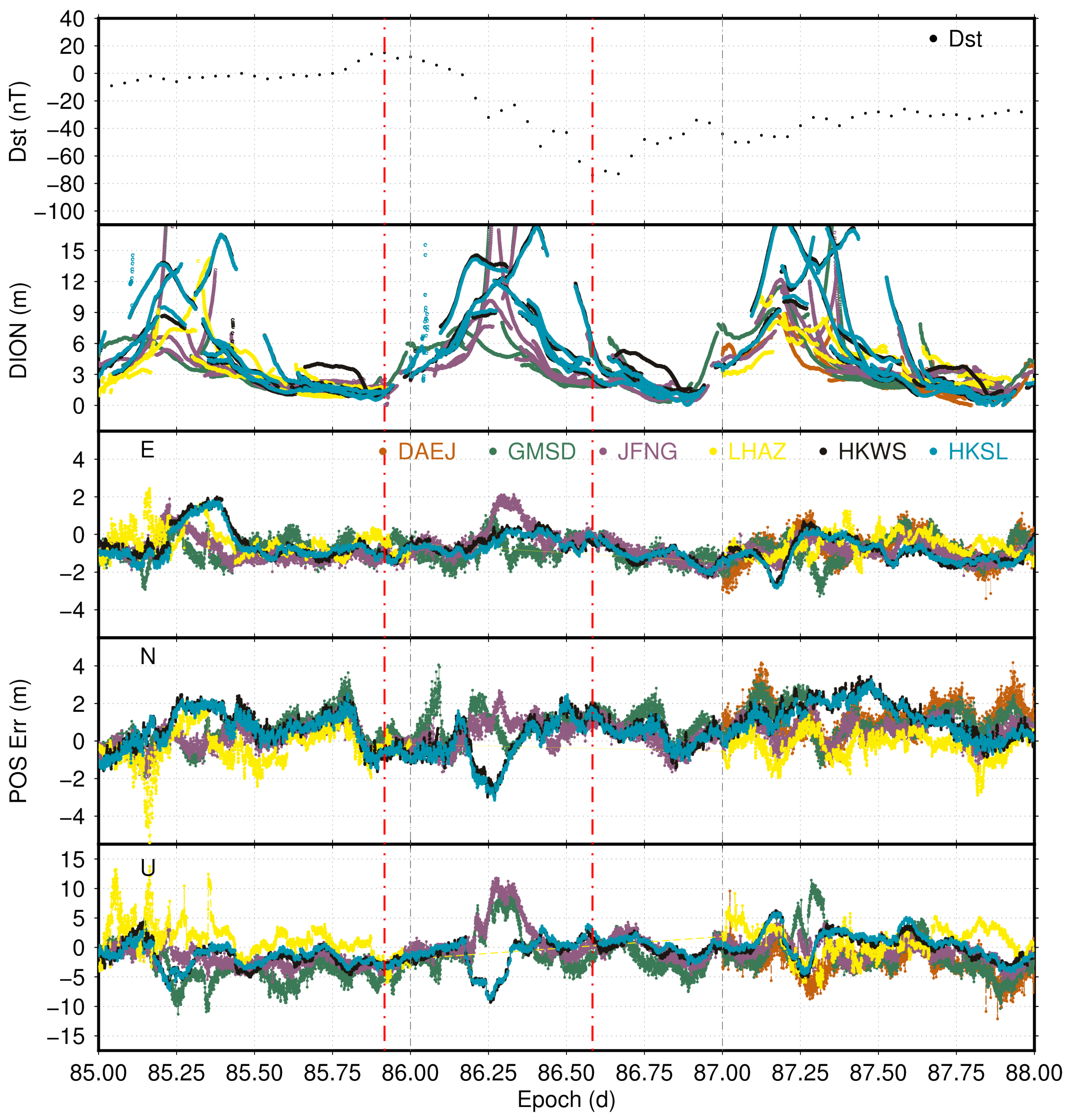
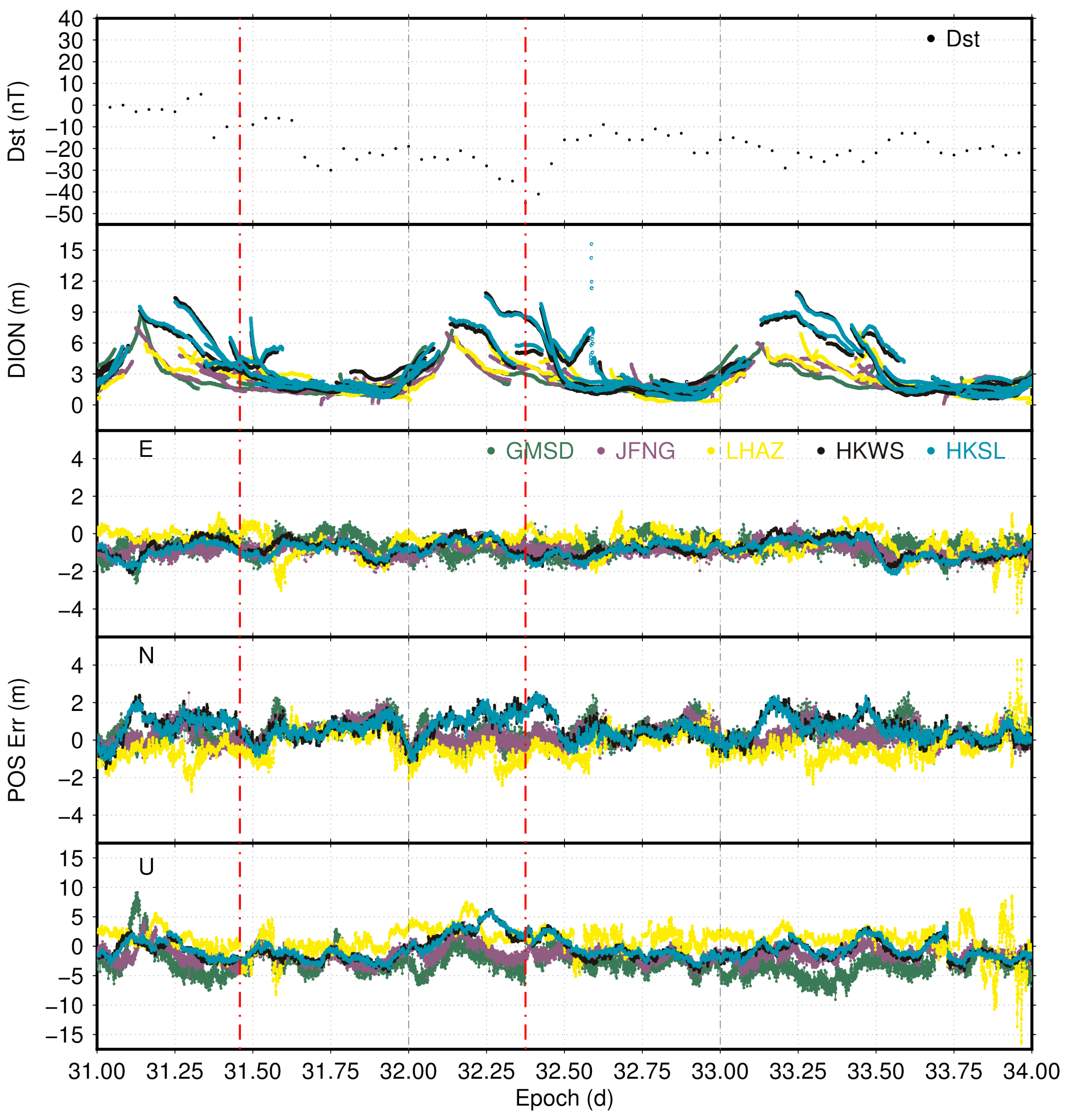
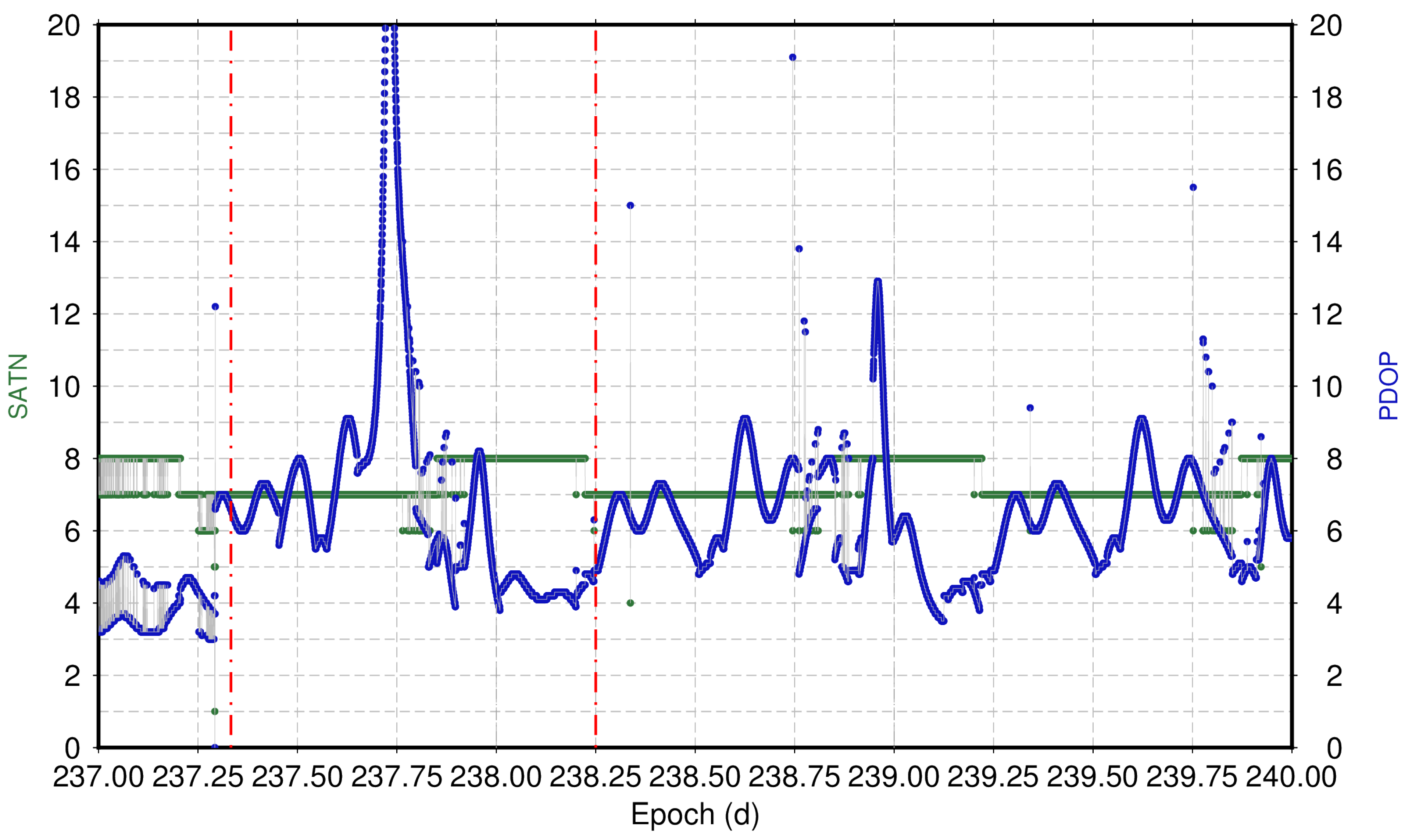
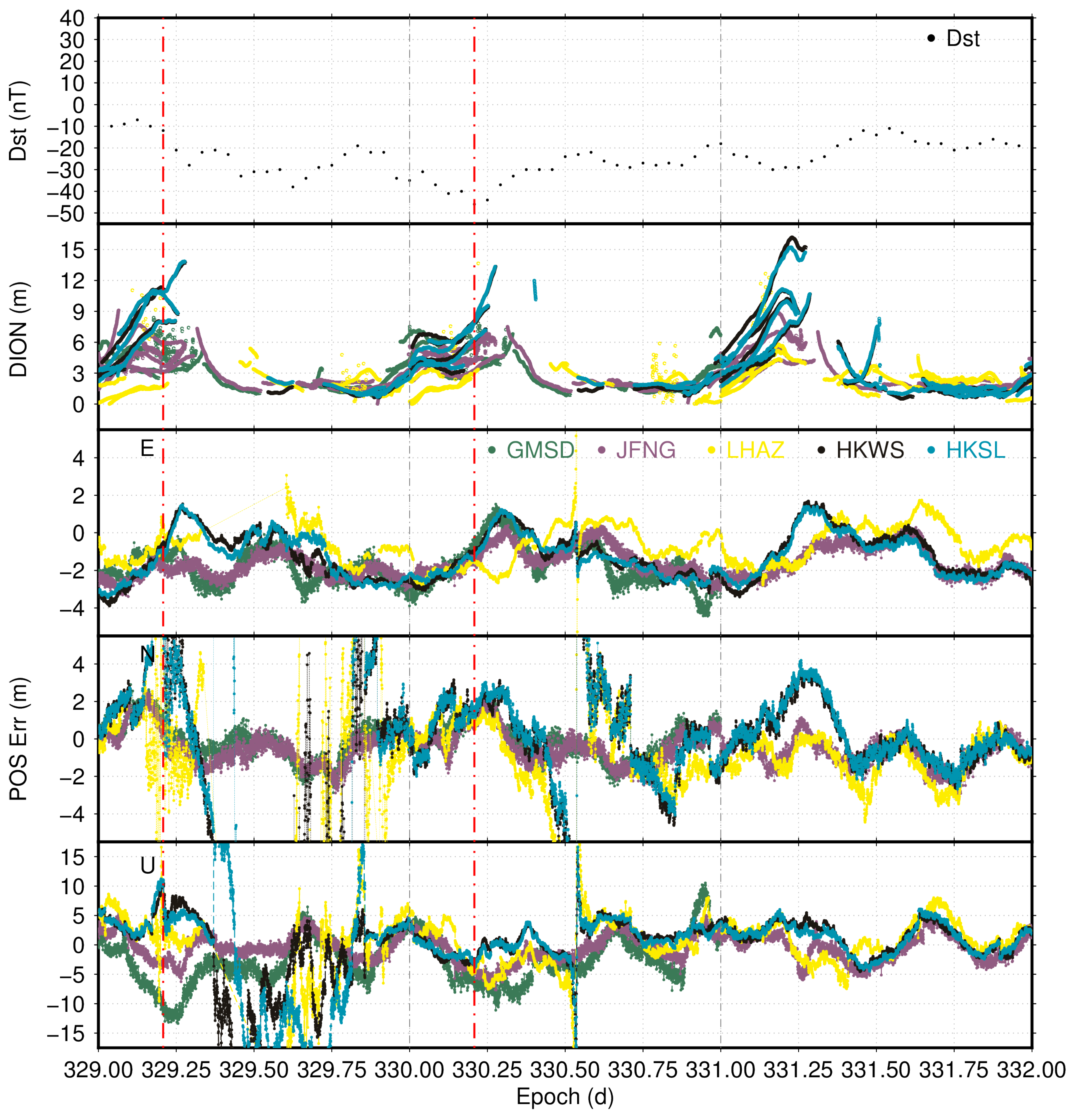
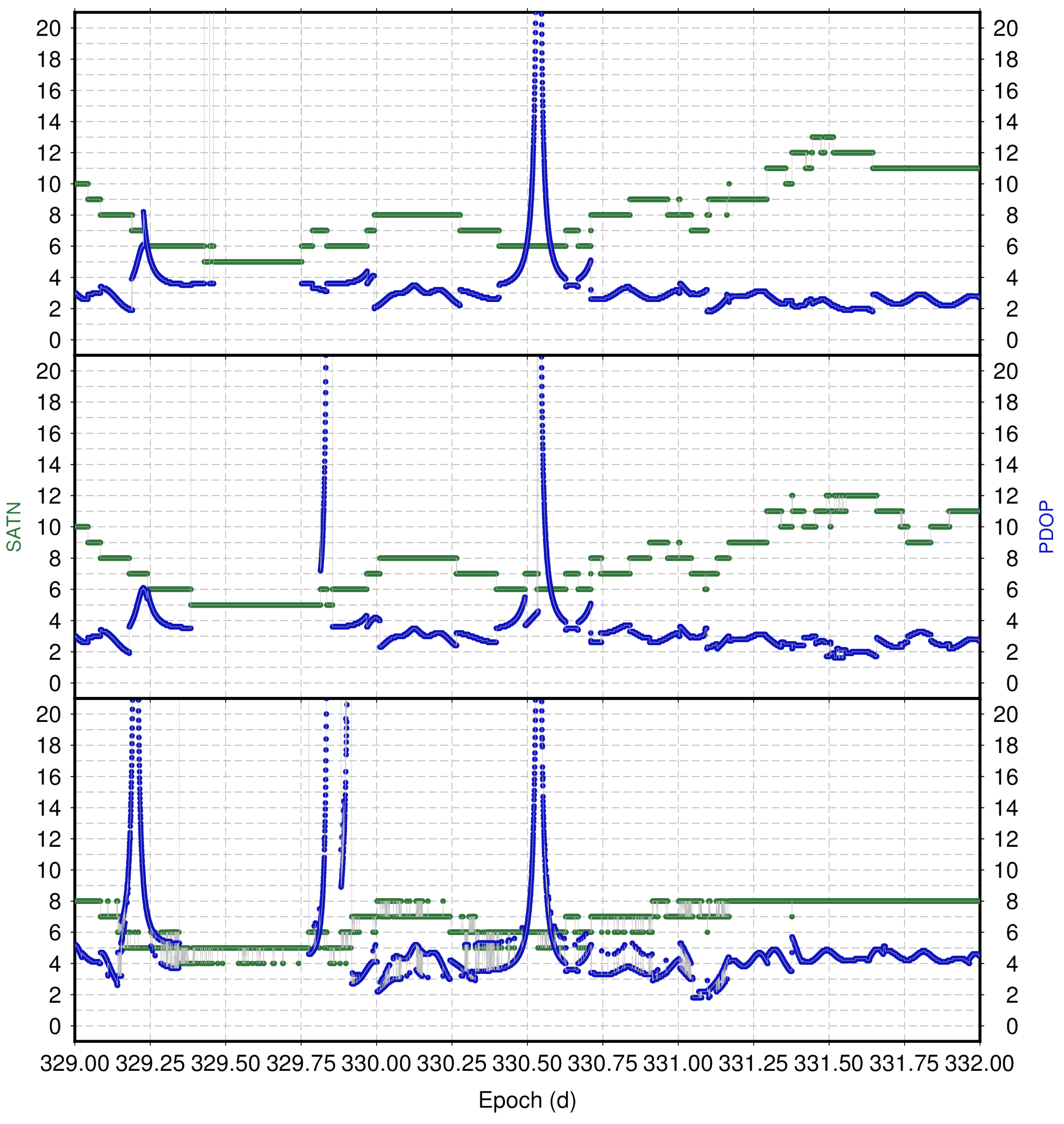
3. Results and Discussion
4. Conclusions
Author Contributions
Funding
Data Availability Statement
Acknowledgments
Conflicts of Interest
Abbreviations
| BDS | BeiDou Navigation Satellite System |
| SPP | Standard Point Positioning |
| RMSE | Root Mean Square Error |
| Dst | Disturbance Storm Time |
| IMF | Interplanetary Magnetic Field |
| GNSS | Global Navigation Satellite System |
| LT | Local Time |
| GPS | Global Positioning System |
| LOL | Loss of Lock |
| RTK | Real-Time Kinematic |
| PPP | Precise Point Positioning |
| DCB | Differential Code Bias |
| SRB | Solar Radio Burst |
| BNC | BKG Ntrip Client |
| PDOP | Position Dilution of Precision |
| GEO | Geostationary Earth Orbit |
| IGSO | Inclined Geosynchronous Orbit |
| MEO | Medium Earth Orbit |
| MGEX | Multi-GNSS Experiment |
| TEC | Total Electron Content |
References
- Gonzalez, W.D.; Joselyn, J.A.; Kamide, Y.; Kroehl, H.W.; Rostoker, G.; Tsurutani, B.T.; Vasyliunas, V.M. What is a geomagnetic storm? J. Geophys. Res. Space Phys. 1994, 99, 5771–5792. [Google Scholar] [CrossRef]
- Hori, T.; Lui, A.T.Y.; Ohtani, S.; C:son Brandt, P.; Mauk, B.H.; McEntire, R.W.; Maezawa, K.; Mukai, T.; Kasaba, Y.; Hayakawa, H. Storm-time convection electric field in the near-Earth plasma sheet. J. Geophys. Res. Space Phys. 2005, 110. [Google Scholar] [CrossRef] [Green Version]
- Owens, M.J.; Forsyth, R.J. The Heliospheric Magnetic Field. Living Rev. Sol. Phys. 2013, 10, 5. [Google Scholar] [CrossRef]
- Loewe, C.A.; Prölss, G.W. Classification and mean behavior of magnetic storms. J. Geophys. Res. Space Phys. 1997, 102, 14209–14213. [Google Scholar] [CrossRef]
- Lastovicka, J. Effects of geomagnetic storms in the lower ionosphere, middle atmosphere and troposphere. J. Atmos. Terr. Phys. 1996, 58, 831–843. [Google Scholar] [CrossRef]
- Danilov, A.; Lastovicka, J. Effects of geomagnetic storms on the ionosphere and atmosphere. Int. J. Geomagn. Aeron. 2001, 2, 209–224. [Google Scholar]
- Sreeja, V.; Devasia, C.V.; Ravindran, S.; Pant, T.K.; Sridharan, R. Response of the equatorial and low-latitude ionosphere in the Indian sector to the geomagnetic storms of January 2005. J. Geophys. Res. Space Phys. 2009, 114. [Google Scholar] [CrossRef]
- BeiDou ICD. Beidou Navigation Satellite System Signal in Space Interface Control Document Open Service Signal (Version 2.0). 2013. Available online: http://www.beidou.gov.cn (accessed on 20 January 2022).
- Wu, X.; Hu, X.; Wang, G.; Zhong, H.; Tang, C. Evaluation of COMPASS ionospheric model in GNSS positioning. Adv. Space Res. 2013, 51, 959–968. [Google Scholar] [CrossRef]
- Yuan, Y.; Wang, N.; Li, Z.; Huo, X. The BeiDou global broadcast ionospheric delay correction model (BDGIM) and its preliminary performance evaluation results. Navigation 2019, 66, 55–69. [Google Scholar] [CrossRef] [Green Version]
- Rama Rao, P.V.S.; Gopi Krishna, S.; Vara Prasad, J.; Prasad, S.N.V.S.; Prasad, D.S.V.V.D.; Niranjan, K. Geomagnetic storm effects on GPS based navigation. Ann. Geophys. 2009, 27, 2101–2110. [Google Scholar] [CrossRef] [Green Version]
- Astafyeva, E.; Yasyukevich, Y.; Maksikov, A.; Zhivetiev, I. Geomagnetic storms, super-storms, and their impacts on GPS-based navigation systems. Space Weather 2014, 12, 508–525. [Google Scholar] [CrossRef]
- Jin, Y.; Oksavik, K. GPS Scintillations and Losses of Signal Lock at High Latitudes During the 2015 St. Patrick’s Day Storm. J. Geophys. Res. Space Phys. 2018, 123, 7943–7957. [Google Scholar] [CrossRef]
- Bergeot, N.; Bruyninx, C.; Defraigne, P.; Pireaux, S.; Legrand, J.; Pottiaux, E.; Baire, Q. Impact of the Halloween 2003 ionospheric storm on kinematic GPS positioning in Europe. GPS Solut. 2011, 15, 171–180. [Google Scholar] [CrossRef]
- Jacobsen, K.S.; Schäfer, S. Observed effects of a geomagnetic storm on an RTK positioning network at high latitudes. J. Space Weather Space Clim. 2012, 2, A13. [Google Scholar] [CrossRef] [Green Version]
- Andalsvik, Y.L.; Jacobsen, K.S. Observed high-latitude GNSS disturbances during a less-than-minor geomagnetic storm. Radio Sci. 2014, 49, 1277–1288. [Google Scholar] [CrossRef]
- Jacobsen, K.S.; Andalsvik, Y.L. Overview of the 2015 St. Patrick’s day storm and its consequences for RTK and PPP positioning in Norway. J. Space Weather. Space Clim. 2016, 6, A9. [Google Scholar] [CrossRef]
- Abe, O.E.; Paparini, C.; Ngaya, R.H.; Otero Villamide, X.; Radicella, S.M.; Nava, B. The storm-time assessment of GNSS-SBAS performance within low latitude African region using a testbed-like platform. Astrophys. Space Sci. 2017, 362, 1–19. [Google Scholar] [CrossRef]
- Zhang, W.; Zhang, D.H.; Xiao, Z. The influence of geomagnetic storms on the estimation of GPS instrumental biases. Ann. Geophys. 2009, 27, 1613–1623. [Google Scholar] [CrossRef]
- Xue, J.; Aquino, M.; Veettil, S.V.; Hu, X.; Quan, L. Performance of BDS Navigation Ionospheric Model during the Main Phase of Different Classified Geomagnetic Storms in China Region. Radio Sci. 2020, 55, e2019RS007033. [Google Scholar] [CrossRef]
- Montenbruck, O.; Steigenberger, P.; Prange, L.; Deng, Z.; Zhao, Q.; Perosanz, F.; Romero, I.; Noll, C.; Stürze, A.; Weber, G.; et al. The Multi-GNSS Experiment (MGEX) of the International GNSS Service (IGS)—Achievements, prospects and challenges. Adv. Space Res. 2017, 59, 1671–1697. [Google Scholar] [CrossRef]
- Sreeja, V.; Aquino, M.; de Jong, K. Impact of the 24 September 2011 solar radio burst on the performance of GNSS receivers. Space Weather 2013, 11, 306–312. [Google Scholar] [CrossRef]
- Weber, G.; Mervart, L.; Stürze, A. BKG Ntrip Client (BNC): Version 2.12; Verlag des Bundesamtes für Kartographie und Geodäsie: 2016. Available online: https://software.rtcm-ntrip.org/export/7214/ntrip/trunk/BNC/src/bnchelp.html (accessed on 1 January 2022).
- Biqiang, Z.; Weixing, W.; Libo, L.; Tian, M. Morphology in the total electron content under geomagnetic disturbed conditions: Results from global ionosphere maps. Ann. Geophys. 2007, 25, 1555–1568. [Google Scholar] [CrossRef] [Green Version]
- Quan, L.; Xue, J.; Hu, X.; Li, L.; Liu, D.; Wang, D. Performance of GPS single frequency standard point positioning in China during the main phase of different classified geomagnetic storms. Chin. J. Geophys. 2021, 64, 3030–3047. [Google Scholar]


| Type | Dst (nT) | ΔT (h) |
|---|---|---|
| Strong | −100 | 3 |
| Moderate | −50 | 2 |
| Weak (typical substorm) | −30 | 1 |
| TYPE | MJD0 | YEAR0 | MON0 | DAY0 | DOY0 | HOUR0 | Dst0 (nT) | MJD1 | YEAR1 | MON1 | DAY1 | DOY1 | HOUR1 | Dst1 (nT) | Duration (h) |
|---|---|---|---|---|---|---|---|---|---|---|---|---|---|---|---|
| STR | 57,098 | 2015 | 3 | 17 | 76 | 5 | 56 | 57,098 | 2015 | 3 | 17 | 76 | 22 | −223 | 17 |
| 57,195 | 2015 | 6 | 22 | 173 | 6 | 13 | 57,196 | 2015 | 6 | 23 | 174 | 4 | −204 | 22 | |
| 57,302 | 2015 | 10 | 7 | 280 | 2 | −9 | 57,302 | 2015 | 10 | 7 | 280 | 22 | −124 | 20 | |
| 57,375 | 2015 | 12 | 19 | 353 | 22 | 43 | 57,376 | 2015 | 12 | 20 | 354 | 22 | −155 | 24 | |
| 58,355 | 2018 | 8 | 25 | 237 | 8 | 19 | 58,356 | 2018 | 8 | 26 | 238 | 6 | −174 | 22 | |
| MED | 57,180 | 2015 | 6 | 7 | 158 | 19 | 24 | 57,181 | 2015 | 6 | 8 | 159 | 8 | −73 | 13 |
| 57,273 | 2015 | 9 | 8 | 251 | 20 | −2 | 57,274 | 2015 | 9 | 9 | 252 | 12 | −98 | 16 | |
| 57,406 | 2016 | 1 | 19 | 19 | 19 | 15 | 57,407 | 2016 | 1 | 20 | 20 | 16 | −93 | 21 | |
| 57,838 | 2017 | 3 | 26 | 85 | 22 | 15 | 57,839 | 2017 | 3 | 27 | 86 | 14 | −74 | 16 | |
| 58,064 | 2017 | 11 | 7 | 311 | 4 | 25 | 58,065 | 2017 | 11 | 8 | 312 | 1 | −74 | 21 | |
| MNM | 57,544 | 2016 | 6 | 5 | 157 | 8 | 32 | 57,545 | 2016 | 6 | 6 | 158 | 6 | −44 | 22 |
| 57,716 | 2016 | 11 | 24 | 329 | 5 | −12 | 57,717 | 2016 | 11 | 25 | 330 | 5 | −46 | 24 | |
| 57,784 | 2017 | 1 | 31 | 31 | 11 | −5 | 57,785 | 2017 | 2 | 1 | 32 | 9 | −45 | 22 | |
| 57,920 | 2017 | 6 | 16 | 167 | 7 | 30 | 57,920 | 2017 | 6 | 16 | 167 | 23 | −31 | 16 | |
| 58,269 | 2018 | 5 | 31 | 151 | 21 | 5 | 58,270 | 2018 | 6 | 1 | 152 | 19 | −39 | 22 |
| SITE | LATITUDE | LONGITUDE | RECEIVER | ANTENNA | YEAR | DOY |
|---|---|---|---|---|---|---|
| DAEJ | 36.40 | 127.37 | TRIMBLE NETR9 | TRM59800.00 TRM59800.00 | 2017 2015 | 087 075 |
| GMSD | 30.56 | 131.02 | TRIMBLE NETR9 | TRM41249.00 TRM59800.00 | 2017 2018 | 311 151 |
| JFNG | 30.52 | 114.49 | TRIMBLE NETR9 | TRM59800.00 | 2015 | 075 |
| LHAZ | 29.66 | 91.10 | LEICA GR25 | LEIAR25.R4 | 2016 | 157 |
| HKWS | 22.43 | 114.34 | LEICA GR25 LEICA GR50 | LEIAR25.R4 | 2015 2017 | 353 031 |
| HKSL | 22.37 | 113.93 | LEICA GR25 LEICA GR50 | LEIAR25.R4 | 2015 2016 | 353 329 |
| MJD | SITE | MIN | MAX | BIAS | RMSE | ||||||||
|---|---|---|---|---|---|---|---|---|---|---|---|---|---|
| 57,098 | GMSD | −4.95 | −2.62 | −3.75 | 0.66 | 3.01 | 16.84 | −1.08 | −0.21 | 1.68 | 1.45 | 0.88 | 3.37 |
| JFNG | −3.69 | −3.53 | −4.04 | 1.39 | 4.45 | 10.21 | −1.20 | −0.19 | 1.75 | 1.41 | 1.33 | 2.97 | |
| 57,196 | GMSD | −2.91 | −2.34 | −9.22 | 0.31 | 1.81 | 7.59 | −1.08 | 0.07 | −0.29 | 1.23 | 0.81 | 3.59 |
| JFNG | −2.26 | −3.51 | −5.23 | 1.10 | 1.90 | 8.03 | −0.52 | −0.19 | 1.87 | 0.91 | 0.97 | 3.26 | |
| 57,302 | GMSD | −4.71 | −5.17 | −12.09 | 0.69 | 7.01 | 17.00 | −1.32 | −0.12 | −1.08 | 1.52 | 2.26 | 5.29 |
| JFNG | −2.52 | −3.95 | −6.42 | 1.28 | 4.29 | 10.31 | −0.88 | −0.16 | 0.01 | 1.14 | 1.60 | 2.85 | |
| 57,376 | GMSD | −4.18 | −2.90 | −7.59 | 1.20 | 31.76 | 33.54 | −0.93 | 1.11 | 2.89 | 1.34 | 3.25 | 6.45 |
| JFNG | −2.50 | −2.54 | −4.61 | 3.66 | 4.49 | 22.24 | −0.20 | 0.93 | 4.69 | 1.46 | 1.79 | 7.92 | |
| 58,356 | DAEJ | −2.54 | −1.31 | −7.65 | 2.15 | 3.94 | 4.87 | 0.25 | 0.43 | −0.98 | 0.54 | 0.80 | 1.98 |
| GMSD | −1.37 | −0.97 | −5.89 | 1.17 | 2.83 | 9.57 | 0.09 | 0.39 | −0.66 | 0.40 | 0.71 | 2.34 | |
| JFNG | −1.07 | −1.33 | −4.17 | 1.43 | 2.06 | 7.54 | 0.17 | 0.38 | −0.98 | 0.41 | 0.61 | 1.83 | |
| LHAZ | −2.12 | −2.74 | −11.67 | 2.44 | 3.83 | 15.37 | 0.10 | 0.63 | −0.40 | 0.71 | 1.02 | 2.95 | |
| HKWS | −0.77 | −0.51 | −3.30 | 1.33 | 3.60 | 7.93 | 0.09 | 0.95 | 0.23 | 0.41 | 1.22 | 2.20 | |
| HKSL | −0.79 | −0.71 | −2.73 | 1.03 | 3.77 | 7.47 | −0.01 | 0.93 | 0.10 | 0.37 | 1.25 | 1.93 | |
| MEAN | −2.60 | −2.44 | −6.31 | 1.42 | 5.63 | 12.75 | −0.47 | 0.35 | 0.63 | 0.95 | 1.32 | 3.50 | |
| MEDIAN | −2.51 | −2.58 | −5.56 | 1.24 | 3.80 | 9.89 | −0.36 | 0.39 | 0.06 | 1.03 | 1.12 | 2.96 | |
| MJD | SITE | MIN | MAX | BIAS | RMSE | ||||||||
|---|---|---|---|---|---|---|---|---|---|---|---|---|---|
| 57,181 | GMSD | −1.66 | −2.05 | −10.40 | 0.42 | 1.40 | 2.41 | −0.46 | 0.15 | −3.84 | 0.63 | 0.50 | 5.01 |
| JFNG | −2.26 | −2.90 | −5.98 | 2.23 | 2.29 | 9.07 | −0.67 | −0.15 | 1.09 | 1.09 | 1.15 | 3.82 | |
| 57,274 | GMSD | −4.13 | −2.02 | −14.74 | 1.47 | 5.17 | 6.92 | −1.42 | 0.83 | −3.69 | 1.76 | 1.71 | 5.40 |
| JFNG | −2.64 | −2.25 | −10.34 | 0.60 | 2.98 | 7.24 | −1.02 | 0.15 | −1.61 | 1.32 | 1.07 | 3.44 | |
| 57,407 | GMSD | −3.26 | −4.09 | −8.82 | 0.35 | 3.86 | 4.35 | −1.70 | 0.04 | −1.54 | 1.83 | 1.27 | 2.76 |
| JFNG | −2.57 | −2.99 | −5.18 | 0.31 | 2.41 | 5.55 | −1.30 | −0.06 | 0.05 | 1.42 | 0.96 | 2.03 | |
| HKWS | −2.11 | −2.66 | −5.93 | 1.59 | 3.89 | 9.51 | −0.69 | 1.13 | 2.28 | 1.16 | 1.86 | 3.86 | |
| HKSL | −2.22 | −2.97 | −4.11 | 1.55 | 3.99 | 11.98 | −0.70 | 1.16 | 2.97 | 1.24 | 1.87 | 4.26 | |
| 57,839 | GMSD | −2.29 | −1.30 | −7.93 | 1.58 | 4.06 | 9.35 | −0.72 | 0.73 | −0.39 | 0.94 | 1.07 | 3.67 |
| JFNG | −1.87 | −1.65 | −4.70 | 2.13 | 2.69 | 11.78 | −0.19 | 0.40 | 1.41 | 0.90 | 0.85 | 4.01 | |
| LHAZ | −1.47 | −0.89 | −5.93 | −0.02 | 0.60 | −0.18 | −0.92 | −0.24 | −2.47 | 0.98 | 0.37 | 2.78 | |
| HKWS | −1.59 | −2.99 | −9.33 | 0.63 | 2.32 | 3.23 | −0.43 | −0.09 | −1.39 | 0.64 | 1.17 | 3.06 | |
| HKSL | −1.61 | −3.16 | −8.81 | 0.33 | 2.47 | 3.93 | −0.56 | −0.25 | −1.22 | 0.73 | 1.22 | 3.05 | |
| 58,065 | DAEJ | −1.30 | −2.07 | −10.97 | 1.84 | 4.20 | 4.34 | 0.33 | 0.83 | −2.57 | 0.66 | 1.27 | 3.55 |
| GMSD | −1.48 | −2.00 | −6.87 | 2.01 | 3.13 | 4.18 | 0.27 | 0.34 | −1.28 | 0.61 | 0.84 | 2.33 | |
| JFNG | −1.55 | −1.56 | −5.70 | 1.76 | 2.53 | 2.80 | 0.05 | 0.50 | −1.98 | 0.48 | 0.90 | 2.48 | |
| LHAZ | −1.68 | −1.26 | −4.74 | 1.71 | 2.16 | 7.08 | −0.18 | 0.17 | −0.78 | 0.70 | 0.65 | 2.20 | |
| HKWS | −1.86 | −1.72 | −3.89 | 1.28 | 3.72 | 2.53 | 0.06 | 0.37 | −0.78 | 0.44 | 1.00 | 1.62 | |
| HKSL | −1.86 | −1.76 | −3.87 | 1.12 | 3.84 | 2.54 | −0.07 | 0.35 | −0.76 | 0.42 | 1.02 | 1.70 | |
| MEAN | −2.07 | −2.23 | −7.28 | 1.20 | 3.04 | 5.72 | −0.54 | 0.33 | −0.87 | 0.94 | 1.09 | 3.21 | |
| MEDIAN | −1.86 | −2.05 | −5.98 | 1.47 | 2.98 | 4.35 | −0.56 | 0.34 | −1.22 | 0.90 | 1.07 | 3.06 | |
| MJD | SITE | MIN | MAX | BIAS | RMSE | ||||||||
|---|---|---|---|---|---|---|---|---|---|---|---|---|---|
| 57,545 | GMSD | −2.28 | −3.36 | −9.62 | 1.98 | 3.89 | 4.97 | −0.42 | 0.32 | −2.04 | 0.95 | 1.50 | 3.17 |
| JFNG | −2.32 | −3.30 | −6.13 | 0.62 | 4.24 | 5.24 | −0.67 | 0.29 | −0.58 | 0.82 | 1.35 | 2.18 | |
| LHAZ | −4.40 | −3.98 | −19.90 | 2.46 | 7.16 | 9.04 | 0.42 | 0.11 | 1.40 | 0.98 | 1.27 | 3.60 | |
| HKWS | −2.63 | −4.36 | −7.30 | 0.65 | 4.83 | 9.12 | −0.82 | 0.23 | 1.41 | 0.99 | 1.95 | 3.07 | |
| HKSL | −2.89 | −4.64 | −6.25 | 0.78 | 4.87 | 9.27 | −0.88 | 0.23 | 1.56 | 1.10 | 1.95 | 3.00 | |
| 57,717 | GMSD | −3.89 | −2.87 | −13.36 | −0.09 | 1.96 | 6.45 | −2.00 | −0.23 | −2.67 | 2.15 | 0.86 | 4.87 |
| JFNG | −3.07 | −2.89 | −6.26 | −0.58 | 2.03 | 4.75 | −1.92 | −0.56 | −0.38 | 1.98 | 0.94 | 2.09 | |
| LHAZ | −3.01 | 71.06 | −39.24 | 3.07 | 29.86 | 16.22 | −0.99 | −3.19 | 0.11 | 1.43 | 10.71 | 5.59 | |
| HKWS | −3.06 | 93.21 | −39.35 | 1.54 | 14.19 | 10.45 | −1.26 | −12.34 | −3.34 | 1.76 | 23.58 | 9.12 | |
| HKSL | −2.97 | 84.15 | −28.16 | 1.49 | 50.08 | 23.53 | −1.20 | −13.47 | −3.46 | 1.69 | 30.80 | 11.09 | |
| 57,785 | GMSD | −1.97 | −1.36 | −6.58 | 0.67 | 2.25 | 2.89 | −0.63 | 0.44 | −2.49 | 0.80 | 0.77 | 3.03 |
| JFNG | −2.06 | −1.55 | −5.41 | 0.08 | 2.13 | 4.08 | −0.81 | 0.33 | −1.32 | 0.89 | 0.66 | 2.03 | |
| LHAZ | −3.03 | −2.44 | −8.28 | 0.73 | 1.77 | 7.53 | −0.57 | −0.32 | 1.10 | 0.83 | 0.84 | 2.61 | |
| HKWS | −1.67 | −1.20 | −4.29 | 0.20 | 2.28 | 6.27 | −0.68 | 0.67 | −0.19 | 0.79 | 0.92 | 2.45 | |
| HKSL | −1.57 | −1.14 | −3.91 | 0.14 | 2.15 | 6.10 | −0.77 | 0.67 | −0.02 | 0.85 | 0.90 | 2.44 | |
| 57,920 | DAEJ | −2.80 | −2.02 | −8.70 | 1.06 | 3.21 | 3.15 | −0.91 | 0.55 | −2.09 | 1.05 | 1.05 | 3.12 |
| GMSD | −2.77 | −1.91 | −10.43 | 0.85 | 2.12 | 2.43 | −0.98 | 0.27 | −2.46 | 1.14 | 0.80 | 3.29 | |
| JFNG | −2.10 | −1.88 | −3.52 | 0.51 | 2.04 | 3.48 | −0.60 | 0.17 | 0.19 | 0.76 | 0.74 | 1.40 | |
| LHAZ | −1.71 | −4.44 | −0.80 | 0.61 | 7.71 | 8.47 | −0.63 | 0.23 | 3.72 | 0.80 | 1.47 | 4.11 | |
| HKWS | −2.00 | −3.11 | −1.73 | 0.28 | 2.93 | 4.95 | −0.58 | −0.50 | 0.98 | 0.76 | 1.11 | 1.76 | |
| HKSL | −1.96 | −3.21 | −1.81 | 0.53 | 1.73 | 4.89 | −0.44 | −0.54 | 1.00 | 0.73 | 1.07 | 1.74 | |
| 58,270 | DAEJ | −2.43 | −2.66 | −9.93 | 1.42 | 2.95 | 9.50 | −0.18 | 0.30 | −1.83 | 0.61 | 0.77 | 2.58 |
| GMSD | −1.72 | −1.99 | −7.34 | 1.28 | 2.06 | 1.10 | −0.17 | 0.11 | −2.75 | 0.52 | 0.60 | 3.15 | |
| JFNG | −2.00 | −2.05 | −5.99 | 1.13 | 2.25 | 2.46 | −0.15 | 0.38 | −2.10 | 0.61 | 0.83 | 2.52 | |
| LHAZ | −1.96 | −1.51 | −5.99 | 1.56 | 2.03 | 7.14 | −0.46 | 0.70 | −1.44 | 0.82 | 0.97 | 2.71 | |
| HKWS | −0.83 | −0.89 | −4.83 | 1.33 | 2.42 | 1.86 | 0.23 | 0.88 | −1.44 | 0.51 | 1.08 | 1.95 | |
| HKSL | −0.93 | −0.65 | −4.18 | 1.32 | 2.07 | 1.65 | 0.17 | 0.81 | −1.32 | 0.53 | 0.97 | 1.81 | |
| MEAN | −2.37 | 11.40 | −9.97 | 0.95 | 6.19 | 6.56 | −0.66 | −0.87 | −0.76 | 0.99 | 3.35 | 3.35 | |
| MEDIAN | −2.28 | −2.66 | −6.26 | 0.78 | 2.28 | 5.24 | −0.63 | 0.23 | −1.32 | 0.83 | 0.97 | 2.71 | |
| MJD | MIN | MAX | BIAS | RMSE | ||||||||
|---|---|---|---|---|---|---|---|---|---|---|---|---|
| MEAN | −2.29 | −2.48 | −6.77 | 0.81 | 3.05 | 5.28 | −0.60 | 0.23 | −0.57 | 0.92 | 1.06 | 2.70 |
| MEDIAN | −2.08 | −2.25 | −6.19 | 0.70 | 2.25 | 4.96 | −0.62 | 0.28 | −0.95 | 0.82 | 0.96 | 2.60 |
Publisher’s Note: MDPI stays neutral with regard to jurisdictional claims in published maps and institutional affiliations. |
© 2022 by the authors. Licensee MDPI, Basel, Switzerland. This article is an open access article distributed under the terms and conditions of the Creative Commons Attribution (CC BY) license (https://creativecommons.org/licenses/by/4.0/).
Share and Cite
Xue, J.; Veettil, S.V.; Aquino, M.; Hu, X.; Quan, L.; Liu, D.; Guo, P.; Wu, M. Performance of BDS B1 Frequency Standard Point Positioning during the Main Phase of Different Classified Geomagnetic Storms in China and the Surrounding Area. Remote Sens. 2022, 14, 1240. https://doi.org/10.3390/rs14051240
Xue J, Veettil SV, Aquino M, Hu X, Quan L, Liu D, Guo P, Wu M. Performance of BDS B1 Frequency Standard Point Positioning during the Main Phase of Different Classified Geomagnetic Storms in China and the Surrounding Area. Remote Sensing. 2022; 14(5):1240. https://doi.org/10.3390/rs14051240
Chicago/Turabian StyleXue, Junchen, Sreeja Vadakke Veettil, Marcio Aquino, Xiaogong Hu, Lin Quan, Dun Liu, Peng Guo, and Mengjie Wu. 2022. "Performance of BDS B1 Frequency Standard Point Positioning during the Main Phase of Different Classified Geomagnetic Storms in China and the Surrounding Area" Remote Sensing 14, no. 5: 1240. https://doi.org/10.3390/rs14051240