Article

Research on Co-Channel Interference Cancellation for Underwater Acoustic MIMO Communications

1
College of Ocean and Earth Sciences, Xiamen University, Xiamen 361005, China
2
Key Laboratory of Underwater Acoustic Communication and Marine Information Technology of the Ministry of Education, Xiamen University, Xiamen 361005, China
*
Author to whom correspondence should be addressed.
Remote Sens. 2022, 14(19), 5049; https://doi.org/10.3390/rs14195049
Submission received: 5 August 2022 / Revised: 11 September 2022 / Accepted: 27 September 2022 / Published: 10 October 2022
(This article belongs to the Special Issue Underwater Communication and Networking)

Abstract

:
Multiple-input–multiple-output (MIMO) communication systems utilize multiple transmitters to send different pieces of information in parallel. This offers a promising way to communicate at a high data rate over bandwidth-limited underwater acoustic channels. However, underwater acoustic MIMO communication not only suffers from serious inter-symbol interference, but also critical co-channel interference (CoI), both of which degrade the communication performance. In this paper, we propose a new framework for underwater acoustic MIMO communications. The proposed framework consists of a CoI-cancellation-based channel estimation method and channel-estimation-based decision feedback equalizer (CE-DFE) with CoI cancellation functionalities for underwater acoustic MIMO communication. We introduce a new channel estimation model that projects the received signal to a specific subspace where the interference is free; therefore, the CoI is cancelled. We also introduce a CE-DFE with CoI cancellation by appending some filters from traditional CE-DFE. In addition, the traditional direct adaptive decision feedback equalization (DA-DFE) method and the proposed method are compared in terms of communication performance and computational complexity. Finally, the sea trial experiment demonstrates the effectiveness and merits of the proposed method. The proposed method achieves a more than 1 dB of output SNR over traditional DA-DFE, and is less sensitive to parameters. The proposed method provides a new approach to the design of robust underwater acoustic MODEM.

1. Introduction

In recent years, the demand for underwater acoustic communication is increasing, such as ocean remote sensing [1], resource exploitation, ocean environmental monitoring, the use of smart autonomous underwater vehicles [2], etc. The underwater acoustic communication has attracted increasing attention.
Compared with radio wireless channels, underwater acoustic channels are much more complicated. Specifically, because of the boundary, the multipath could extend from several milliseconds to hundreds of milliseconds, which leads to severe inter-symbol interference (ISI). Since the underwater sound propagates at an extremely low speed, slight movements between the transmitter and receiver lead to significant Doppler shifts. Moreover, the carrier frequency for communication is less than 100 kHz, and the bandwidth for communication is limited, especially for long-range communication. Under such difficult channels, high-speed and long-range acoustic communication is a great challenge.
Generally speaking, there are two kinds of modulation technologies that can counteract the complicated underwater acoustic channels: single carrier modulation and multicarrier modulation. Multicarrier modulation, such as orthogonal frequency-division multiplexing (OFDM) [3,4,5], has a substantial ability to combat channel distortions using cyclic prefix (CP) or zero padding (ZP), and the frequency-domain equalization (FDE) reduces the computational complexity. However, the usage of CP or ZP degrades the bandwidth efficiency. Moreover, the frequency-domain equalizer performs a block-wise process, the duration of a block is typically large, and it is assumed that, within a block, the channel is time-invariant; therefore, it is not applicable in fast-varying channels. In addition, the OFDM systems suffer from a high peak-to-average power ratio, which leads to difficulties in designing power amplifiers. However, single carrier modulation has the advantage of a high spectral efficiency and a fast channel-tracking ability.
Under limited-bandwidth acoustic channels, one promising approach to increase the data rate is to use multiple transmitters; this system is referred to as a multiple-input–multiple-output (MIMO) system. Unfortunately, despite suffering from ISI caused by the multipath, the MIMO system also suffers from serious co-channel interference (CoI), which introduces a lot of noise in the per-channel channel decoding process. In the last two decades, underwater acoustic MIMO communications have been investigated in [6,7,8,9,10,11,12,13,14,15,16,17,18] to fundamentally increase the achievable data rate. Due to interference among concurrent transmission streams, powerful detection algorithms are highly in demand. The most effective way to deal with ISI and CoI is channel equalization for underwater acoustic MIMO systems. The channel equalization for single-carrier MIMO communication includes frequency-domain equalizers [6,7,8] and time-domain equalizers [9,10,11,12,13,14,15,16,17]. In [6], a single-carrier receiver scheme with bandwidth-efficient FDE was proposed. The proposed algorithm implemented an overlapped-window FDE by partitioning a large block into small subblocks, and a decision-direct channel estimation algorithm was incorporated into the overlapped-window FDE to track channel variations and improve error performance. The proposed FDE reduced the average bit error rate compared to traditional single-carrier equalization by 74.4% and 84.6% for the 400 m and 1000 m range systems. In [7], a frequency-domain turbo-equalization scheme without CP or ZP was proposed for single-carrier MIMO communication. In the first iteration, a low-complexity detection was used in the frequency domain; in the second iteration, inter-block-interference and CP were applied to enable effective symbol detection. Its feasibility and effectiveness have been tested by field trial data. In [8], a three-step frequency-domain equalization scheme was described for MIMO underwater acoustic communication. The first iteration was channel estimation, the second iteration was to suppress CoI, and the final iteration was to equalize symbols. The traditional frequency domain equalizers need CP or ZP to prevent inter-block interference, which degrades the bandwidth efficiency. Some methods may not need CP or ZP [7], but serval iterations are performed for decoding, which increases the computational complexity.
A common approach to decode MIMO symbols is direct adaptive decision feedback equalization (DA-DFE). Due to the serious Doppler shift in underwater acoustic channels, a phase-tracking module is usually required. For example, a second-order phase-locked loop was adopted for DA-DFE in [19]. After phase compensation, the DA-DFE approach uses adaptive algorithms, such as least mean square (LMS) and recursive least square (RLS) criteria to train the equalizer’s taps or equalize received symbols. The merit of DA-DFE is not necessary to explicitly estimate the channel, but the DA-DFE approach requires long training sequences to achieve convergence, which degrades the spectral efficiency. Due to the easy implementation of DA-DFE, it was intensively used to equalize underwater acoustic single-input–multiple-output (SIMO) systems [20,21,22] or MIMO systems [9,10,11,12,18]. In [9], space–time trellis codes layered with space–time codes combined with low-complexity DA-DFE was proposed. The space–time trellis codes layered with space–time codes utilized the large diversity, and the ISI and the CoI were suppressed by the DA-DFE. A data rate of 48 kb/s in 23 kHz of bandwidth, and 12 kb/s in 3 kHz of bandwidth were achieved in the 2 km range. In [10], a time-reversal-based underwater acoustic MIMO communication was proposed. A parallel interference cancellation method was incorporated to suppress the CoI in the MIMO system, while the DA-DFE was used to frequently update the channel used for the time reversal process. In [11], both serial and parallel interference cancellation techniques were integrated with time reversal DA-DFE to address the CoI in underwater acoustic MIMO systems. High bandwidth efficiencies were achieved in the experiment. In [18], a joint sparsity for underwater acoustic MIMO communication was proposed, distributed compressed sensing was used to estimate the underwater acoustic channel, and then time reversal was adopted to suppress the multipath and combine multiple channels. Finally, a single-channel DA-DFE was applied to decode symbols. In [12], many kinds of sparse DA-DFEs with the proportionate-updating or the zero-attracting adaptive filtering principles were compared. To reduce the computational complexity, a partial tap update scheme via hard thresholding was introduced to sparse DA-DFEs. The results revealed that, although the improved DA-DFEs show a more improved performance, the RLS DA-DFE still achieved the best performance. The DA-DFE parameters (such as the length of feedforward filter, the iterative step, and the forgotten factor) require careful manual achieving to achieve the considerable performance. When the channel is varied, those parameters should subsequently be updated. Hence, this is not suitable for the design of a robust MIMO communication system.
The turbo equalization method, which utilizes multiple iterations, was used to decode MIMO symbols [13,14,15]. Turbo equalization typically consists of two components: a soft-input–soft-output equalizer and a soft-input–soft-output decoder, which iteratively exchange extrinsic information to improve the detection performance. For example, in [13] the NLMS-algorithm-based DA-DFEs were used in a soft-input–soft-output equalizer. The DA-DFEs consisted of a feedforward filtering unit and soft interference cancellation unit; the experiment verified the effectiveness of the proposed method. In [14,15], the IPNLMS algorithm or RLS-DCD algorithm was used for iterative channel estimation in turbo equalization, and a minimum mean-square-error equalizer was used to detect the symbols. However, the interference cancellation was not considered in channel estimation. Other methods also were proposed for underwater MIMO communications. For example, in [17], sparse learning via iterative minimization was used in the estimation channel; then linear minimum mean-square error criterion was used to detect symbols. After the 1st iteration, the CoI was subtracted from the received signal. This process was iteratively performed. However, when the decoded symbols are incorrect, the reconstructed CoI will introduce a lot of noise, and this noise will propagate to the next iteration; hence, the detection of symbols will fail.
In a single-input–multiple-output (SIMO) system, CE-DFE was demonstrated to achieve a better performance and was widely investigated. The CE-DFE directly estimates the channel using shorter training sequences, and directly calculates the equalizer’s taps based on channel estimates. In [23], the CE-DFE was used for multi-band underwater acoustic channel equalization; in [24], the CE-DFE was utilized in a time-varying underwater acoustic channel. However, due to the heavy CoI, the traditional CE-DFE, which was used for SIMO communication systems, will fail when it is used in underwater acoustic communications. To date, the literature reporting on CE-DFE that is suitable for underwater acoustic MIMO communications has been very limited. In [16], we proposed a CE-DFE with CoI cancellation component for underwater acoustic MIMO communication, but the channel estimation still suffered from serious interference. The limitations of the existing methods are listed in Table 1.
As mentioned, the CE-DFE taps were achieved via channel estimates, which provide prior information for equalizers. Some efforts have been taken to improve the performance of channel estimation under an impulsive noise environment [25,26,27,28], but very limited work focuses on interference cancellation for single-carrier MIMO channel estimation. In [16], we proposed distributed compressed sensing to enhance the channel estimates with common delays, but the different delays still suffered from serious CoI. Our previous work did not fully deal with the CoI.
In this paper, we propose a new framework that combines both the CoI-cancellation-based channel estimation method and CoI-cancellation-based CE-DFE. As far as we know, this is the first time that the CoI-cancellation-based channel estimation and CoI-cancellation-based channel equalization have been proposed. Specifically, in channel estimation, we use the projection method to project CoI to a specific subspace in which the CoI in this subspace is free. As a result, the CoI is cancelled. In channel equalization, we introduce CE-DFE with CoI cancellation to underwater acoustic MIMO communication. The proposed methods do not need to reconstruct the CoI, and can perfectly address the CoI, whether or not the CoI from different tranmitters is serious. In addition, to date, there has been no detailed comparison between traditional DA-DFE and CE-DFE. In this paper, the performance is compared in terms of output SNR and computational complexity between CE-DFE and DA-DFE for underwater acoustic MIMO communications. Compared to DA-DFE, the proposed receiver does not need to carefully tune parameters such as the length of taps, forgotten factor, etc. Moreover, since the CE-DFE performs block by block, the Doppler can be estimated and compensated block by block, while the DA-DFE is usually sensitive to Doppler, which has an impact on convergence. In a word, the proposed method for MIMO communication is more robust to the complicated underwater acoustic channel, and the proposed MIMO receiver provides an available scheme for the design of high-speed underwater acoustic communication systems.
The contributions of this paper are as follows:
  • We propose a novel receiver for underwater acoustic MIMO communication. The proposed receiver consists of channel estimation with CoI cancellation and channel equalization with CoI cancellation.
  • In Ref. [29], only two transmitters were considered for underwater acoustic MIMO channel estimation. Without loss of generality, in this paper, we extend the number of transmitters to more than two. Additionally, we analyze the performance of the proposed channel estimation method.
  • We compare the difference between the proposed CE-DFE receiver and the traditional DA-DFE receiver in terms of analysis and experimental results. The results demonstrate that the proposed receiver achieves better communication performance, and the proposed receiver is not sensitive to parameters; therefore it provides an alternative to the design of a robust underwater acoustic MIMO MODEM.
The remainder of this paper is organized as follows. In Section 2, the framework for underwater acoustic MIMO system with CoI cancellation, including channel estimation and channel equalization, is expressed. In Section 3, the results and analysis are described. Finally, some conclusions are drawn in Section 4. The following notations are used in this paper. Bold upper-case and lower-case letters denote matrices and column vectors, respectively. Superscripts ( · ) T , ( · ) H denote transpose and Hermitian transpose. Notation i = 1 M P i denotes multiplication from P 1 to P M . Notation · 2 denotes l 2 norm. Notation E ( · ) denotes the expectation. Notation I is the identity matrix, A ( : , i ) denotes a vector from i-th column of matrix A .

2. MIMO System Design with CoI Cancellation

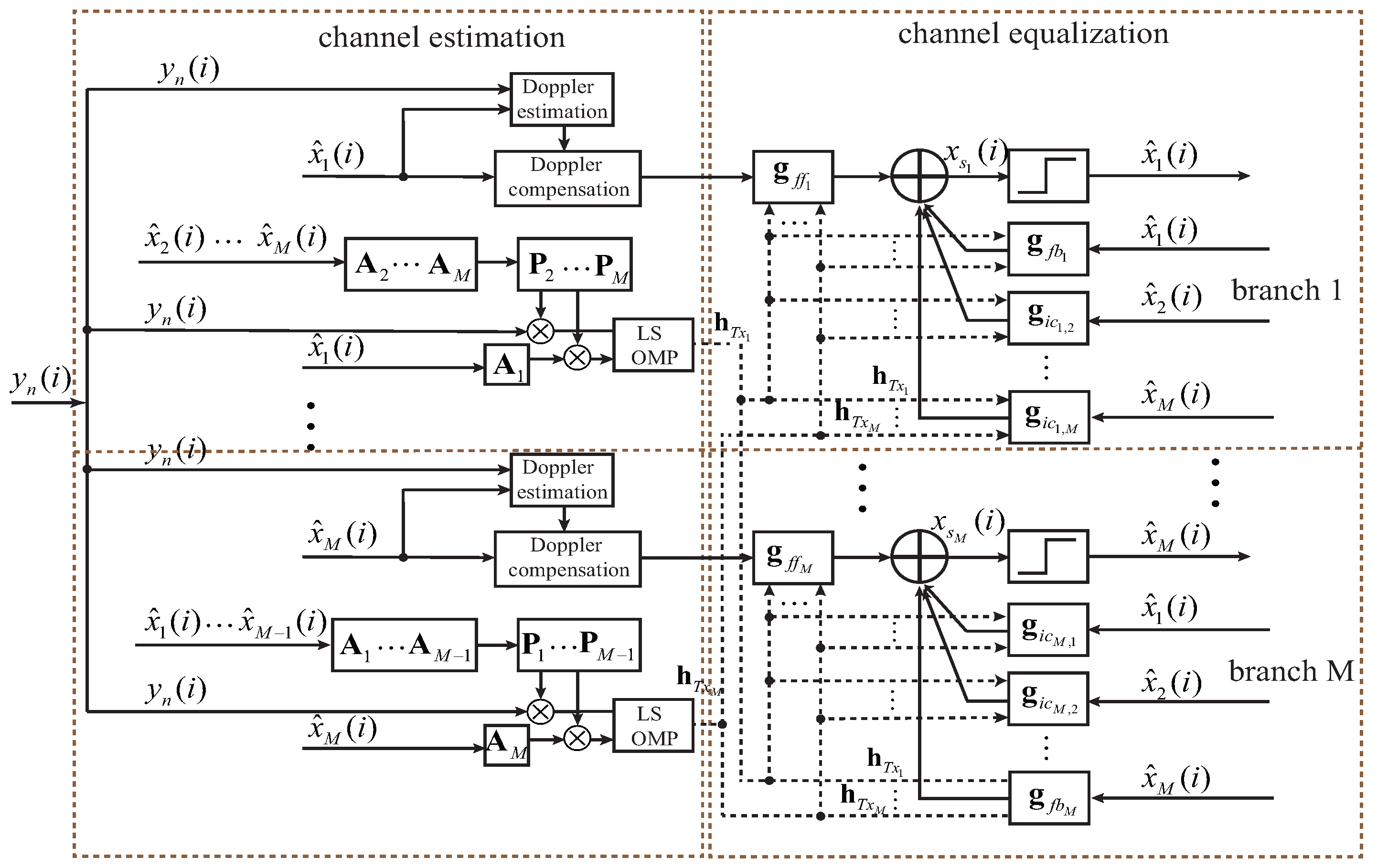
2.1. System Overview

The structure of the proposed receiver is illustrated in Figure 1. The proposed method works with a number of M CE-DFEs. For each CE-DFE, there are two stages: one channel estimator with interference cancellation (IC), Doppler estimation and compensation, and one decision feedback equalizer with IC. The proposed receiver works in training mode if the decoded symbols are known; otherwise, it works in the decision-directed mode. Before channel estimation and channel equalization, the Doppler estimation and Doppler compensation are performed using decoded symbols. In the channel estimator, we utilize the decoded symbols to construct projection matrix P m , whose purpose is to project the interference to a specific subspace and to free the interference in the subspace. As a result, the channel estimation performance will be improved. If the projection matrix equals the unit matrix, the proposed channel estimation model reduces to the traditional channel estimation model, which cannot mitigate the interference. In Figure 1, filters g f f and g f b are the feedforward and feedback filters, respectively. We added filter g i c based on traditional CE-DFE in [30]. The purpose of this filter g i c is to mitigate the interference. Differing from DA-DFE, which uses various criteria to achieve filter taps, the filters g f f , g f b , and g i c are measured by channel estimates. Compared with traditional CE-DFE, the proposed receiver not only removes the CoI in channel equalization, but also removes it in channel estimation; therefore, the performance of the proposed method will be significantly improved. In the following, we will demonstrate the proposed receiver in detail.

2.2. Projection Based Channel Estimation

At present, the CoI cancellation is typically performed in channel equalization; however, the literature investigating the role of CoI cancellation in channel estimation is very limited. For CE-DFE, the filter taps are obtained from channel estimates; thus, the accuracy of the channel estimation determines the channel equalization performance. In this subsection, we introduce a projection-based channel estimation. The signal received in baseband at n-th hydrophone can be expressed as:
y n ( i ) = m = 1 M ( l = 0 L 1 x m ( i l ) h m , n ( l ) ) + w n ( i ) .
In (1), x m ( i ) is transmitted symbols from m-th transmitter, where m = 1 , 2 , , M , and M is the number of total transmitters. Notation y n ( i ) is the received signal at n-th hydrophone; h m , n ( i ) is the channel from m-th transmitter to n-th receiver; w n ( i ) is the ambient noise. L is the channel length.
It is assumed that the channel is time invariant over a number of S samples; then, (1) can be written in matrix form, such as
y n = m = 1 M A m h m , n + w n ,
where
A m = x m ( L 1 ) x m ( L 2 ) x m ( 0 ) x m ( L ) x m ( L 1 ) x m ( 1 ) x m ( L + S 2 ) x m ( L + S 3 ) x m ( S 1 ) ,
y n = y n ( L 1 ) y n ( L ) y n ( L + S 2 ) T ,
h m , n = h m , n ( L 1 ) h m , n ( L 2 ) h m , n ( 0 ) T ,
w n = w n ( L 1 ) w n ( L ) w n ( L + S 2 ) T .
When estimating the channel from i-th transmitter h i , n , the signals received from other transmitters are the co-channel interference. Traditional channel estimation methods do not consider the CoI cancellation; the CoI is treated as noise, and the SNR received from a specific transmitter is low. This results in a lower channel estimation and channel equalization accuracy. The orthogonal projection method is used to cancel such CoIs. The main idea of the orthogonal projection is that a projection matrix is used to span the received signal to a new subspace, where the interference is free. Our previous work in [29] first applied the projection method to channel estimation, but only two transmitters in the near-far network were considered. In this paper, we extend more than two transmitters for underwater acoustic MIMO channel estimation using the orthogonal projection method.
It is supposed that channel h m , n needs to be estimated, and the interference is canceled in order. That is to say, the interference from transmitter 1 is canceled first, and the interference from transmitter M is canceled last. The cancellation is iteratively performed until the signal from m-th transmitter remains, and interference from other transmitters is removed. When canceling the CoI from transmitter 1, the projection is defined as P 1 = I A 1 ( A 1 H A 1 ) 1 ) A 1 H . Left multiplying P 1 to (2), it can be obtained
P 1 y n = P 1 A 1 h 1 , n + m = 2 M P 1 A m h m , n + P 1 w n = m = 2 M P 1 A m h m , n + P 1 w n .
The second step is to cancel the interference from transmitter 2. The projection matrix is defined as P 2 = I ( P 1 A 2 ) ( ( P 1 A 2 ) H ( P 1 A 2 ) ) 1 ( P 1 A 2 ) H . Similarly, by left multiplying P 2 to (7), the received signal can be expressed as
P 2 P 1 y n = P 2 A 2 h 2 , n + m = 3 M P 2 P 1 A m h m , n + P 1 P 2 w n = m = 3 M P 2 P 1 A m h m , n + P 1 P 2 w n .
The process continues until all the interference is cancelled.
In general, when sequentially canceling the interference from k-th transmitter, the projection matrix P k is defined as
P k = I B k ( B k H B k ) 1 B k H .
The matrix B k is defined as
B k = ( i = 1 k P i 1 ) A k ,
where P 0 = I , and P m = I . It is interesting to see that
P k B k = B k B k ( B k H B k ) 1 B k H B k = 0 .
Equation (11) is the key principle of the orthogonal projection method.
After all interference is canceled, the remaining signal related to h m , n is
( i = 1 M P i ) y n = ( i = 1 M P i ) A m h m , n + ( i = 1 M P i ) w n .
From (12), one can observe that all the interference is canceled. In Ref. [11], the CoI is sequentially measured and then subtracted from the received signal. If the measured CoI is not accurate, the error will propagate to the next iteration; thus, this results in performance degradation. The proposed channel model does not need to directly measure the CoI, so the performance will be significantly improved. Equation (12) can be directly solved by LS algorithm. When the number of transmitters is M = 2 , the proposed channel model reduces to the case in Ref. [29].

2.3. Channel Estimation Based Decision Feedback Equalization with IC

Considering the channel equalization model, (1) can be written as
y n = m = 1 M G m , n x m + w n .
where G m , n is the channel matrix from the m-th transmitter to the n-th hydrophone, and w n is the ambient noise. Notations y n , x m , w n , and G m , n are defined as follows
y n ( y n ( i + L c ) y n ( i ) y n ( i L a + 1 ) ) T ,
x m ( x m ( i + L c ) x m ( i ) x m ( i L a + 1 ) ) T ,
w n ( w n ( i + L c ) w n ( i ) w n ( i L a + 1 ) ) T ,
G m , n h m , n ( 0 ) 0 0 0 0 h m , n ( L 1 ) 0 0 h m , n ( 0 ) h m , n ( L 1 ) ,
G m , n = G 0 1 | g 1 | F 1 .
In (14)–(16), L c and L a denote the number of causal and a-causal taps, respectively. The lengths of g f f , g f b , and g i c are L f f , L f b , and L i c , respectively. We partition the transmitted symbols into three groups x m = ( x f b m T , x m ( i ) , x 0 m T ) T . Notations x f b m and x 0 m are defined as x f b m T ( x m ( i + L f b ) , x m ( i + L f b 1 ) , , x m ( i + 1 ) ) T and x 0 m ( x m ( i 1 ) , , x m ( i L a L c L + 1 ) T . Similarly, the channel matrices G m , n are partitioned into three groups, as shown in (18). Then, (13) can be written as
y n = m = 1 M ( g m x m ( i ) + F m x f b m + G 0 m x 0 m ) + w n .
From (19), we can observe that the symbols from all transmitters interfere with each other; if no cancellation is applied, the signal-to-noise ratio for each branch will be significantly degraded. In (19), the terms g m x m ( i ) are the transmitted symbols that need to be recovered. As an example to recover x 1 ( i ) , the second term F 1 x f b 1 should be cancelled by feedback filter, and the terms m = 2 M F m x f b m should be cancelled by IC filters. The remaining terms are the effective observation noise that the feedforward filters must try to eliminate.
According to Figure 1, x s m can be represented by
x s m = g f f m H y n + g f b m H x f b m + i = 1 , i m M ( g i c m , i H x f b i ) .
Finally, the coefficients of the filters are measured as (21) (see [16] for complete derivations).
g f f m = ( k = 1 M ( g k g k H + D k ) ) 1 g m .
g f b m = F m g f f m ,
g i c m , k = F k g f f m , k m .
From (21), as we expected, the filters of channel equalization are obtained via channel estimates. The traditional channel estimation method does not perform interference cancellation, and the filters g f f , g f b , and g i c will have plenty of noise; as a result, the channel equalization performance will degrade. In addition, traditional CE-DFE does not have IC filters to eliminate the CoI. In this paper, the proposed method has the functionality to remove the interference in both channel estimation and channel equalization; therefore, the communication performance will be significantly improved.

2.4. Performance Analysis

For convenience, and based on the fact that most underwater acoustic MIMO communication systems utilize two transmitters, in this subsection, we analyze the performance using two transmitters ( M = 2 ) .
Consider the proposed channel model in (12); we used the LS method to analyze the performance. This assumed that the estimated channel is h ^ 1 , n , which can be achieved by least square,
h ^ 1 , n = ( Φ 1 H Φ 1 ) 1 Φ 1 p y n 1 .
Notation Φ 1 is defined as P 2 A 1 and p y n 1 is defined as P 2 y n , where P 2 = ( I A 2 ( A 2 H A 2 ) 1 A 2 H ) . Defining the channel mean square error (MSE) is
M S E = E h ^ 1 , n h 1 , n 2 2 ,
where h 1 , n is the true channel estimate. Then, the channel MSE of h ^ 1 , n is
M S E h 1 , n = E { ( Φ 1 H Φ 1 ) 1 Φ 1 ( Φ 1 h 1 , n + P w 1 ) h 1 , n 2 2 } = E { ( Φ 1 H Φ 1 ) 1 Φ 1 P w 1 2 2 } = E { t r ( P w 1 H Φ 1 ( Φ 1 H Φ 1 ) 2 Φ 1 H P w 1 ) } = t r ( Φ 1 H E { P w 1 P w 1 H } Φ 1 ( Φ 1 H Φ 1 ) 2 ) = t r ( E { P w 1 P w 1 H } ( Φ 1 H Φ 1 ) 1 ) = E { P 2 w n w n H P 2 H } t r ( A 1 H P 2 H P 2 A 1 ) = σ w n 2 t r ( P 2 P 2 H ) t r ( A 1 H P 2 H P 2 A 1 ) .
In (24), notation σ w n 2 is the variance of ambient noise w n . As P 2 H is a projection matrix, it satisfies
P 2 H P 2 = P 2 P 2 H = P 2 H P L P I .
Appendix A proves (25). Then, we can easily obtain
M S E h 1 = σ 2 t r ( A 1 H A 1 ) .
Analogously, consider the traditional way that does not consider CoI; the MSE for h 1 , n is
M S E h 1 , n = E { ( A 1 H A 1 ) 1 A 1 ( A 2 h 2 , n + w n ) 2 2 } = t r ( E { ( A 2 h 2 , n + w n ) ( A 2 h 2 , n + w n ) H } ( A 1 H A 1 ) 1 ) .
It is assumed that the transmitted symbols are white sequences and independent of ambient noise w n and channel estimate; therefore, we can obtain
E { ( A 2 h 2 , n + w n ) ( A 2 h 2 , n + w n ) H } = σ h 2 , n 2 t r ( A 2 A 2 H ) + σ w n 2 .
As a result, the channel MSE, obtained in the traditional way, is
M S E h 1 , n = σ h 2 , n 2 t r ( A 2 A 2 H ) + σ w n 2 t r ( A 1 H A 1 ) .
Comparing (26) to (29), one may see that the MSE obtained by the proposed method is far less than that obtained by traditional method, because the proposed method adopts the orthogonal projection method to remove the CoI. The more accurate channel estimate will provide more precise channel information to CE-DFE.
It is assumed that the estimated channel consists of the true channel estimate G ^ m , n and the erroneous channel estimate matrix E G m , n .
G 1 , n = G ^ m , n + E G m , n .
We combine (19), (20) and (30); the output of CE-DFE for branch 1 is
x s 1 ( i ) = g f f 1 H ( k = 1 2 g k x k ( i ) + k = 1 2 F k x f b k + k = 1 2 G 0 k x 0 k + w n ) + g f b 1 H x f b 1 + g i c 1 , 2 H x f b 2 .
Substituting (21) into (31), the following can be obtained
x s 1 ( i ) = g f f 1 H k = 1 2 g ^ k x k ( i ) + g f f 1 H F ^ 2 x f b 2 + g f f 1 H k = 1 2 ( v k + G ^ 0 k x 0 k ) + g f f 1 k = 1 2 E G k , n x k ,
where v 1 + v 2 = w n . The output error of CE-DFE for brach 1 is
ϵ = x s 1 ( 1 ) x 1 ( i ) = { g f f 1 H k = 1 2 g ^ k x k ( i ) + g f f 1 H F ^ 2 x f b 2 + g f f 1 H k = 1 2 ( v k + G ^ 0 k x 0 k ) x 1 ( i ) } + g f f 1 k = 1 2 E G k , n x k .
The terms in the brace in (33) are called the minimum achievable error of the equalizer. This error can be obtained based on the perfect knowledge of the channel impulse response and noise statistics.
Focusing on the last term in (33), which is called the excess error, one may observe that the excess error related to the channel error has a significant impact on the output error of CE-DFE. The lower the channel estimate error, the lower the CE-DFE error. In sum, the proposed structure for underwater acoustic MIMO communication cancels the CoI, not only in channel estimation, but also in channel equalization; hence, the communication performance significantly improved.

2.5. Computational Complexity Analysis

In this subsection, we simply analyze the computational complexity of the proposed methods, including the channel estimation method and channel equalization method.
Let us first consider the channel estimation model. When canceling the interference from k-th transmitter, the computational complexity of (10) is O ( k S 3 ) + O ( S 2 L ) = O ( S 3 ) . The computational complexity of the term B k H B k is O ( L 2 S ) ; the complexity of the term ( B k H B k ) 1 is O ( L 3 ) ; the complexity of the term B k ( B k H B k ) 1 B k H is O ( S L 2 + S 2 L ) = O ( S 2 L ) . Therefore, the total computational complexity of (9) is O ( S 3 ) + O ( S 2 L ) + O ( S L ) = O ( S 3 ) . The computational complexity of the term ( i = 1 M P i ) y n in (12) is O ( S 2 L ) . When solving the (12) using least square, the computational complexity is also O ( S 3 ) . Since the number of transmitters for underwater acoustic MIMO communication is very limited, the computational complexity of the proposed channel estimation is still O ( S 3 ) .
The main complexity for the channel equalizer is the matrix inverse process. The computational complexity of the term g k g k H is O ( L f f 2 ) ; the complexity complexity matrix inverse in (21a) is O ( L f f 3 ) ; the computational complexity of (21b) and (21c) is O ( L f b L f f ) .
It can be concluded that the computational complexity of the proposed receiver is determined by the training length S and the length of the feedforward filter L f f .

2.6. Relationship between CE-DFE and DA-DFE

The DA-DFE used for underwater acoustic communication can be found in Ref. [9]. Comparing the DA-DFE and the proposed CE-DFE, the structures are almost the same, consisting of a feedforward filter, feedback filters, and IC filters. There are some differences between CE-DFE and DA-DFE.
  • The biggest difference between the DA-DFE and the proposed CE-DFE is that the DA-DFE uses some criteria, such as least mean square or recursive least square, to train the filters, while the CE-DFE uses channel estimates to measure the filters directly. As the underwater acoustic channel is usually typically sparse, channel estimation can be performed using the compressed sensing method, which needs fewer training sequences, while the DA-DFE needs long sequences to achieve convergence.
  • The CE-DFE always performs block by block. It is assumed that, within a data block, the channel is time-invariant, but varied in the next data block. The filters of CE-DFE will not change within one data block. In the decision-directed mode, some periodical training sequences are essential to prevent error propagation, because the decoding symbols are used for Doppler estimation and channel estimation, which may appear as erroneous symbols. Meanwhile, the DA-DFE iterates symbol by symbol, and the DA-DFE filters are updated symbol by symbol; thus, the filters can track the underwater acoustic channel. As a result, the computational complexity of DA-DFE is typically higher than that of CE-DFE, if the filter length relatively large.
  • The Doppler estimation and compensation can be performed block by block for CE-DFE, while the DA-DFE utilizes the phase lock loop to track channel variance.
  • The CE-DFE has fewer controlling parameters than DA-DFE, and DA-DFE is very sensitive to parameters such as the length of filters, forgotten factor and training length. Therefore, the CE-DFE is more robust to underwater acoustic channel.

3. Experimental Results

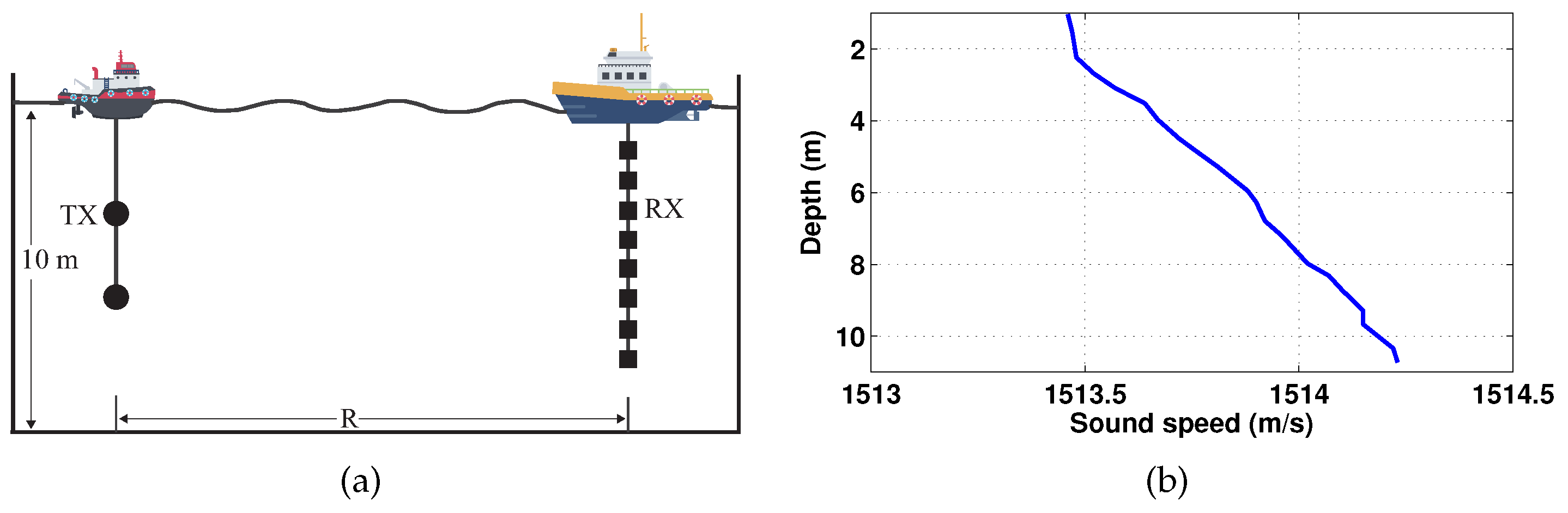
3.1. Experimental Setting
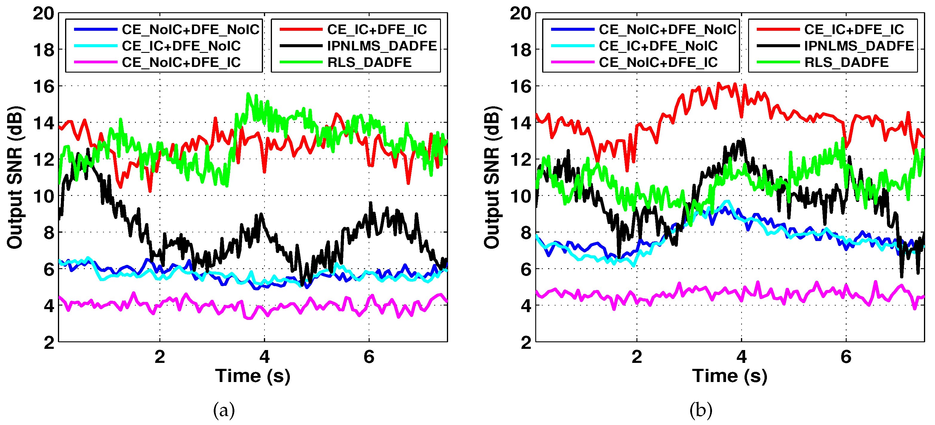
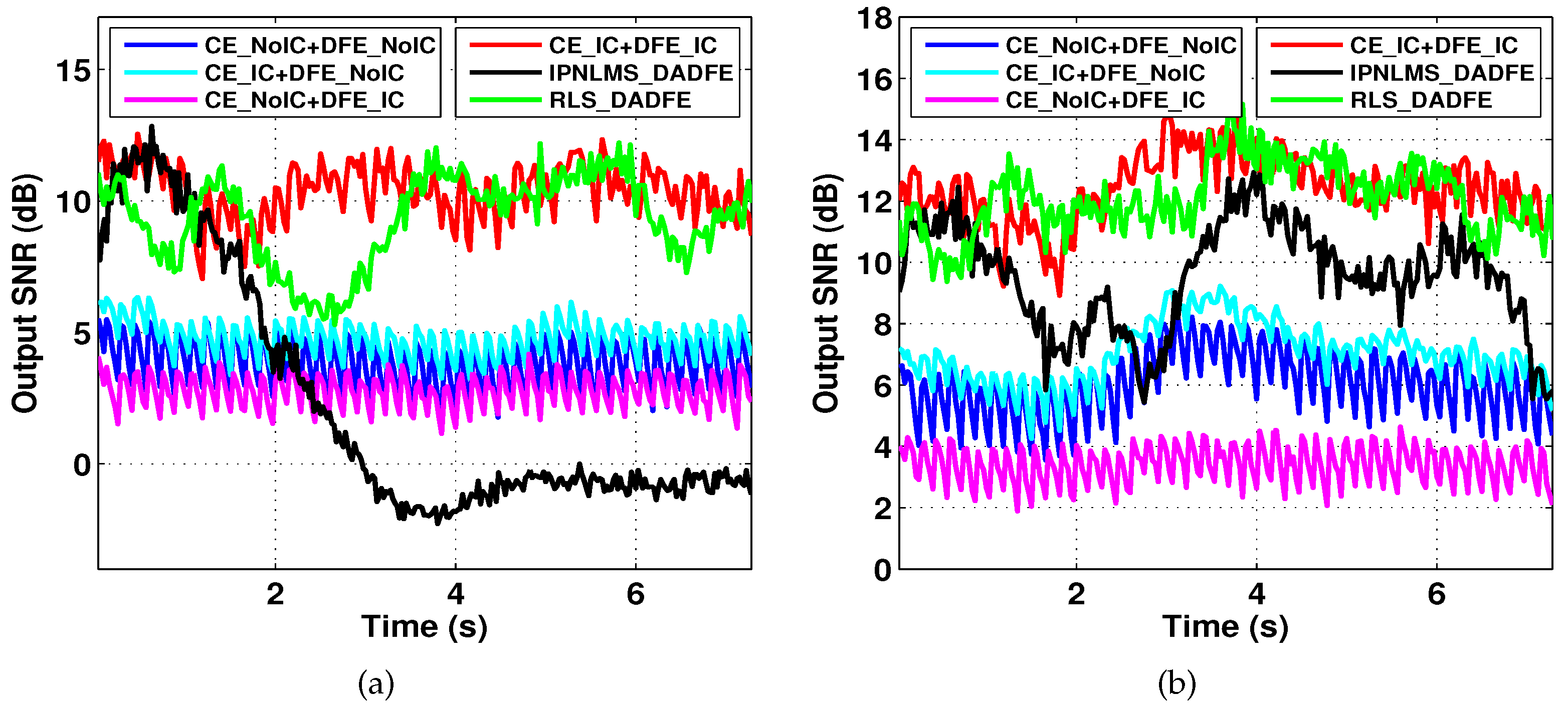
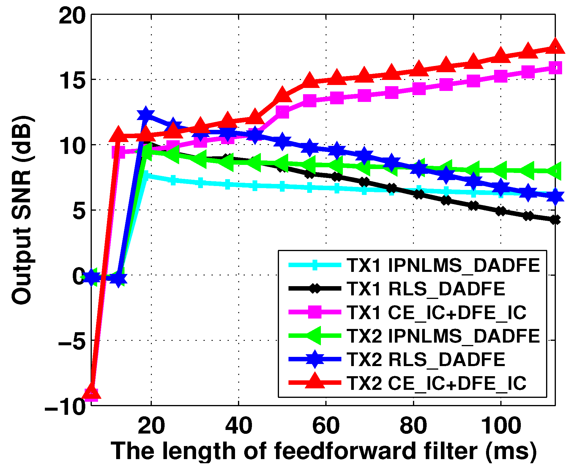
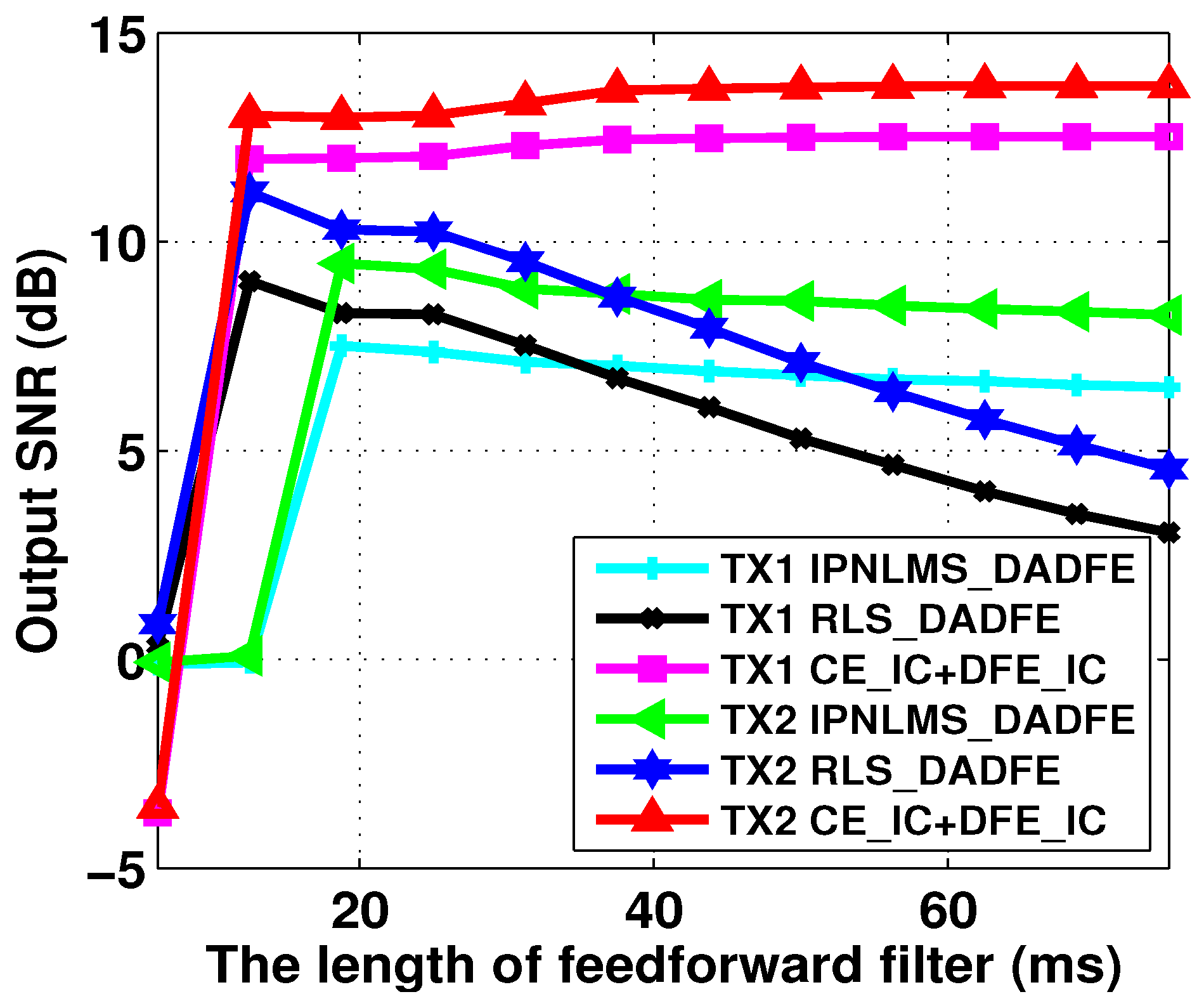
The experiment was conducted in Wuyuan Bay, Xiamen, China. The water depth was about 10 m, and two transmitters were suspended at the depth of 4 m and 6 m, respectively. A vertical receiving array, which consisted of 8 hydrophones, was fixed on a boat with a uniform space of 1 m, as shown in Figure 2a. The transmitters located in 4 m and 6 m are denoted as transmitter 1 and transmitter 2, respectively. The range between transmitters and receivers was approximately 1000 m. The average SNR was 29.3 dB. Figure 2b shows the sound speed profile; from this figure, one may observe that the sound speed varies within 1 m/s. There is an obvious mixed layer above 2.3 m, and the sound speed shows a slight positive distribution.
The parameters of the communication system are shown in Table 2. The bandwidth was 3200 symbols/s, and the quadrature phase shift keying (QPSK) mapping method was used.
In the following section, the proposed CE-DFE receiver will be compared with some CE-DFE-based receivers and a DA-DFE-based receiver. In Ref. [12], the equalizers were compared. The RLS-based DA-DFE and IPNLMS-based DA-DFE achieved the best communication performance. Therefore, in this paper, we utilize the two kinds of DA-DFEs as the benchmark. We define some abbreviations to better describe this.
1 
RLS_DADFE. The receiver can be found in [9]. The filters were obtained by recursive least square.
2 
IPNLMS_DADFE. The receiver can be found in [12]. This is an improved normalized least mean square equalizer.
3 
CE_NoIC+DFE_NoIC. Channel estimation used a traditional model [23] with no interference cancellation. Channel equalization used the traditional CE-DFE [30]; the CE-DFE does not have IC filters.
4 
CE_IC+DFE_NoIC. Channel estimation used the proposed channel model, which has the ability to eliminate interference, but channel equalization does not.
5 
CE_IC+DFE_NoIC. This is the opposite case to CE_IC+DFE_NoIC. The channel estimation used interference cancellation method, but channel equalization does not.
6 
CE_IC+DFE_IC. This is the proposed receiver. Both channel estimation and channel equalization can eliminate interference.
In this paper, we utilize the output SNR to evaluate the communication performance of different kinds of receivers. The output SNR is defined as
ρ m = 10 log 10 | | x m | | 2 2 | | x m x s m | | 2 2 ,
where x m is the transmitter symbols from the m-th transmitter, and x s m is the soft output from the m-th DFE branch. The higher output SNR indicates a better communication performance.

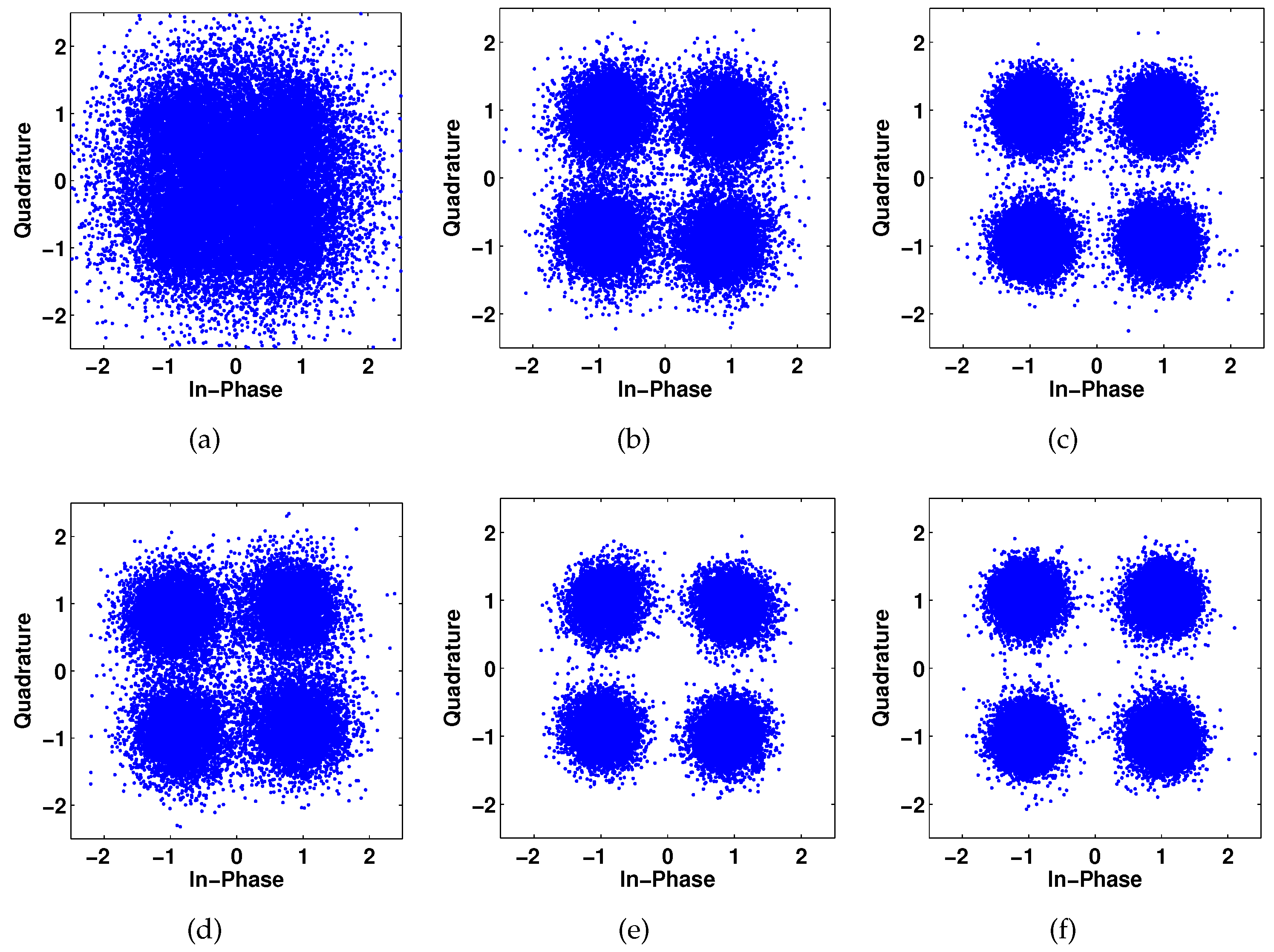
3.2. Results and Analysis

Figure 3 shows the channel estimates. The channel length was set at 62.5 ms, and the observation length S was set to be three times the channel length to achieve accurate channel estimates. The channel estimation method was LSQR [31] in both the traditional channel estimation model and the proposed channel estimation model. Before channel estimation, the Doppler estimation and Doppler compensation were performed. The channel estimate in Figure 3c was obtained by the traditional channel model without IC. From Figure 3c, one may observe that the multipath is obviously rich and the relative delay is more than 20 ms. One also may observe that, in Figure 3c, more estimated noise is caused by CoI. Focusing on Figure 3d, obtained by the proposed method, we can see that the multipath outline is much clearer, and the noise level is much lower. The reason for this is that the proposed channel estimation model projects the CoI to a specific subspace where the CoI is free; thus, it does not suffer from interference, which results improved SNR and lower MSE, as (26) shows. In addition, the multipath from transmitter 2 is much richer than that from transmitter 1.
The communication performance is compared in terms of output SNR. The lengths of feedforward filters, feedback filters, and IC filters for CE-DFE-based receivers were 125 ms (400 symbols), 62.2 ms (199 symbols), and 62.2 ms, respectively. The lengths of feedforward filters, feedback filters, and IC filters for DA-DFE based receivers were 18.75 ms (60 symbols), 9.37 ms (30 symbols), and 9.37 ms, respectively. The forgotten factor for RLS_DADFE was 0.9985; the IPNLMS_DADFE step is 0.25; the remaining parameters for IPNLMS_DADFE are the same as in Ref. [12]. The parameters for RLS_DADFE and IPNLMS_DADFE were chosen carefully to achieve the best communication performance. In the CE-DFE-based receivers, the Doppler was estimated via match filtering [11], while in RLS_DADFE and IPNLMS_DADFE, the phase lock loop was used, and the phase lock loop parameters were the same as in Ref. [19].
Figure 4 shows the output SNR in training mode. In training mode, the input of feedback filter and IC filters is known in advance; in other words, the interference is known. One may observe that the CE_NoIC+DFE_IC receiver and CE_NoIC+DFE_NoIC receiver obtained the lowest output SNR. The reason for this is that, because the traditional channel estimation does not cancel the CoI, the channel estimates contain more estimated noise. The feedforward filters and feedback filters, which are directly measured via channel estimates, also contain a large amount of noise. As shown in (33), the excess error is significant, so the output SNR from channel equalization is low for both the CE_NoIC+DFE_NoIC receiver and CE_NoIC+DFE_IC receiver. Meanwhile, the CE_NoIC+DFE_IC receiver has IC filters; this introduces more noise to the channel equalizer than the CE_NoIC+DFE_NoIC receiver does. In addition, the output from equalizers in the CE_NoIC+DFE_IC receiver is fed to the different branches shown in Figure 1, while the output from the equalizer from CE_NoIC+DFE_NoIC receiver is fed to its own branch. If the equalizer output is not correct, the CE_NoIC+DFE_IC receiver introduces much more noise. As a result, the output SNR obtained by the CE_NoIC+DFE_IC receiver is lower than that obtained by the CE_NoIC+DFE_NoIC receiver. For example, the average output SNR from CE_NoIC+DFE_NoIC and CE_NoIC+DFE_IC for transmitter 1 is 5.71 dB and 3.99 dB, while for transmitter 2 it is 7.80 dB and 4.59 dB, respectively. Looking at the output SNR obtained by the CE_IC+DFE_NoIC receiver in Figure 5, it can be seen that the output SNR is not significantly improved. Although the channel estimation performs interference cancellation, and the CE-DFE filters are more accurate, the interference is not canceled in equalizers. The average output SNR from CE_IC+DFE_NoIC recevier is 5.67 dB for transmitter 1 and 7.65 dB for transmitter 2.
Since the DA-DFE is widely used in underwater acoustic MIMO communication, we utilized DA-DFEs as benchmark. Looking at the output SNR obtained by the DA-DFE based equalizer, one can see the output SNR obtained by RLS_DADFE is much higher than that obtained by IPNLMS_DADFE, as can be seen in Figure 4a,b. The reason for this is that the RLS-based equalizer achieves a lower output error than LMS-based equalizer achieves, but the cost of this better performance is a high computational complexity. One may also observe that the output SNR obtained by IPNLSM_DADFE shows obvious vibrations; the reason for this is that the channel is varied, as shown in Figure 3. The IPNLSM_DADFE cannot track channel variation. Since the RLS_DADFE and IPNLMS_DADFE contain the IC filters, and the filters are obtained via training sequences with specified criteria, the worst channel estimation results would not be introduced to the equalizers. As a result, the output SNR obtained by RLS_DADFE and IPNLMS_DADFE is higher than that obtained by CE_NoIC+DFE_NoIC, CE_NoIC+DFE_IC, and CE_IC+DFE_NoIC. The average output SNR from RLS_DADFE and IPNLMS_DADFE is 12.86 dB and 7.85 dB for transmitter 1, and 10.73 dB and 9.76 dB for transmitter2.
Focusing on the proposed CE_IC+DFE_IC in Figure 5, it can be seen that the output SNR is the highest for both transmitter 1 and transmitter 2; for example, the average output SNR is 13.11 dB and 14.14 dB, respectively. Not only does the channel estimation perform interference cancellation by projecting the CoI onto a specific subspace, the channel equalization utilizes IC filters to remove the interference shown in (19); thus, the SNR output is significantly improved. One can observe that the output SNR obtained by the proposed CE_IC+DFE_IC does not show significant vibration, because the channel estimation and Doppler compensation are performed block by block, and the filters for CE_IC+DFE_IC are updated periodically.
The communication performance is also compared in decision-directed mode. The parameters are the same as they are in the training mode for all equalizers. To prevent error propagation in CE-DFE-based equalizers and DA-DFE-based equalizers, 25% training symbols were periodically inserted.
In Figure 5, the results are similar to those in Figure 4. The obvious difference is that the average output SNR slightly drops for all the receivers. In the decision-directed mode, the input of the feedforward filter and IC filters is the decoded symbols; when the decoded symbols make an erroneous decision, the interference is incorrect, so the output SNR drops. In addition, for the CE-DFE-based equalizers, the decoded symbols are also used for channel estimation. Erroneous symbols will also lead to a worse channel estimation performance. The other difference is that the IPNLMS_DADFE output SNR obtained by IPNLMS_LMS receiver significantly drops in Figure 5a, and IPNLMS_LMS fails to decode the symbols from transmitter 1. The average output SNR obtained by CE_IC+DFE_IC is 10.41 dB and 12.4 dB for transmitter 1 and transmitter 2, respectively. The average output SNR obtained by RLS_DADFE is 9.2 dB and 11.8 dB for transmitter 1 and transmitter 2, respectively. The proposed CE_IC+DFE_IC receiver achieves an average gain of about 1 dB compared to the RLS_DADFE receiver.
The constellations obtained by IPNLMS_DADFE, RLS_DADFE, and CE_IC+DFE_IC receivers in decision-directed mode are provided in Figure 6. One can observe that the constellations are clearly separated obtained by the proposed CE_IC+DFE_IC for both transmitter 1 and transmitter 2; this demonstrates that the proposed receiver achieves a fantastic communication performance. The constellations from transmitter 2 are much more separated than those from transmitter 1. The reason for this could be that, since the depths of the transmitters are different, as shown in Figure 2, the gains in spatial diversity from transmitter 2 are higher than those from transmitter 1.
To illustrate the flexibility of the proposed CE_IC+DFE_IC receiver, we compare the communication performance using different lengths of feedforward filters, feedback filters and IC filters. The lengths of different filters are the same for IPNLMS_DADFE, RLS_DADFE, and the proposed CE_IC+DFE_IC. The lengths of feedback filters and IC filters are half of the length of feedforward filters, while the length of the feedforward filters varied from 6.25 to 112.5 ms. The IPNLMS_DADFE, RLS_DADFE, and the proposed CE_IC+DFE_IC work in training mode. From Figure 7, one may observe that the output SNR obtained by the proposed CE_IC+DFE_IC receiver increases with increasing filter length; the result verifies the theoretical analysis in Ref. [30], concluding that the output SNR increases with increasing filter length. The SNR output obtained by RLS_DADFE decreases when the length of feedforward filter increases. In addition, the output SNR obtained by IPNLMS_LMS almost remains the same. This implies that the performance of IPNLMS_LMS does not rely on the filter length. The output SNR obtained by RLS_DADFE and IPNLMS_DADFE reaches its maximum when the feedforward filter length is 20 ms. One may find that when the length of the feedforward filter is less than 10 ms, it fails to decode; the reason for this is that, in Figure 3, there is no multipath located within 10 ms. Based on Figure 3 and Figure 7, we conclude that, when the strong multipath is located within the window of the feedforward filter, the proposed method achieves a considerable performance.
To further investigate the relationship between the lengths of filters and communication performance, the lengths of feedback filters and IC filters were fixed at 25 ms (80 symbols), while the length of feedforward filters was varied from 12.5–150 ms. The RLS_DADFE, IPNLMS_DADFE, and the proposed CE_IC+DFE_IC receivers also work in training mode. The results are shown in Figure 8. It can be observed that the output SNR obtained by our proposed CE_IC+DFE_IC receiver still slightly increases, while it decreases when obtained by DA-DFE. From Figure 7 and Figure 8, it can be concluded that, when designing underwater acoustic MIMO communication systems, the filter length of the proposed CE_IC+DFE_IC receiver is more flexible. The filter length can be set to as long as possible to cover the long-time delay path and obtain a higher SNR output.
From Figure 7 and Figure 8, we can observe that the gain in output SNR over Tx1 and Tx2 obtained by our proposed CE_IC+DFE_IC receiver is relatively small, while the gain obtained by DA-DFE is significant. Figure 7 and Figure 8 imply that, when designing a MIMO underwater acoustic system, our proposed CE_IC+DFE_IC receiver is fairly suitable as an underwater acoustic channel, because the filter length of our proposed CE_IC+DFE_IC receiver can be set as long as possible, regardless of the length of the real underwater acoustic channel. In other words, our proposed method has more flexibility. However, as shown in Figure 7 and Figure 8, the DA-DFE is very sensitive to filter length, which should be carefully tuned in one scenario and changed in other scenarios. In addition, the DA-DFE is very sensitive to the forgotten factor. In sum, our proposed CE_IC+DFE_IC offers a new approach to the design of a robust underwater acoustic MIMO communication system.
Finally, we compared the computational complexity using the consumption of time. The code runs on the matlab platform in a laptop, the CPU is Intel i7-10510U, and the size of RAM is 16 GB. The sequences with a length of 187.5 ms are used for Doppler estimation, Doppler compensation, and channel estimation in our proposed CE_IC+DFE_IC receiver, while in the DA-DFE receiver, the sequences with a length of 187.5 ms were used to train the filters. After obtaining the equalizer filters, 500 QPSK symbols were equalized for both CE_IC+DFE_IC RLS_DADFE, and IPNLMS_DADFE receivers. The lengths of the feedback filters and IC filters are half the lengths of the feedforward filter. Table 3 shows the average time. It can be observed that the consumption for IPNLMS_DADFE is the shortest, since it does not need the matrix inverse process. However, it does not achieve a considerable performance. Comparing the consumption of RLS_DADFE and the proposed CE_IC+DFE_IC, when the filters length for RLS_DADFE is short, e.g., L f b = 18.7 ms, the consumption for DA-DFE is short; however, when the filter length for RLS_DADFE is relatively long, the consumption is significantly increased. For example, when the filter length time is 62.5 / 18.75 = 3.33 , the consumption time is 4408.8 / 45.85 = 96.1 . However, the consumption of our proposed method almost remains the same. The key reason for this is that the RLS_DADFE performs symbol by symbol, while our proposed method performs block by block. From Table 3, it can be concluded that when the channel length is long, our proposed method has great advantages over RLS_DADFE in terms of computational complexity.

4. Conclusions

The DA-DFE is widely used in underwater acoustic communications, but DA-DFE needs to carefully tune some parameters, such as the length of filters and forgotten factor, to achieve convergence. The CE-DFE’s robustness has been verified in underwater acoustic SIMO communications. However, the traditional CE-DFE, including channel estimation and channel equalization, does not consider CoI when used in MIMO communication, and the communication performance is not improved. To address this issue, in this paper, we proposed a new structure for underwater acoustic MIMO communication. The proposed receiver consisted of channel estimation with IC, and channel equalization with IC. Specifically, in channel estimation, the interference was projected to a new subspace where the interference was free; thus, the channel estimation performance was improved, which provided more accurate channel information for the channel equalizer. In channel equalization, IC filters were added to traditional CE-DFE; thus, the interference was further eliminated. In addition, the traditional DA-DFE and our proposed method were compared in terms of output SNR and time. Finally, the sea trial experiment demonstrated that our proposed method outperformed the traditional DA-DFE and traditional CE-DFE. Since our proposed method did not rely on parameters, it was robust for different underwater acoustic channels. Our proposed method provided a new alternative to the design of underwater acoustic MIMO communication systems. In the future, we will consider implementing the proposed method in hardware, and design an underwater acoustic MIMO MODEM.

Author Contributions

Conceptualization, Y.Z.; methodology, Y.Z.; software, Y.Z.; validation F.T. and X.Y.; formal analysis, Y.Z.; investigation, X.Y.; resources, F.T.; data curation, Y.Z. and F.T.; writing—original draft preparation, Y.Z.; writing—review and editing, Y.Z.; visualization, Y.Z.; supervision; F.T.; project administration, Y.Z.; funding acquisition, Y.Z. All authors have read and agreed to the published version of the manuscript.

Funding

This research was funded in part by the Fundamental Research Funds for the Central Universities (No. 20720210078), in part by National Key Research and Development Program of China (No. 2018YFE0110000), and in part by the Science and Technology Commission Foundation of Shanghai (No. 21DZ1205500).

Institutional Review Board Statement

Not applicable.

Data Availability Statement

The data presented in this paper are available after contacting the corresponding author.

Conflicts of Interest

The authors declare no conflict of interest.

Appendix A. Proof of (25)

In this appendix, we simply provide the proof of (25).
P 2 H P 2 = ( I A 2 ( A 2 H A 2 ) 1 A 2 H ) H ( I A 2 ( A 2 H A 2 ) 1 A 2 H ) = I A 2 ( A 2 H A 2 ) 1 A 2 H ( A 2 ( A 2 H A 2 ) 1 A 2 H ) H + A 2 ( A 2 H A 2 ) 1 A 2 H = I A 2 ( A 2 H A 2 ) 1 A 2 H = P 2 .
In the similar way, it is easy to obtain P 2 P 2 H = P 2 .
It is assumed A ( : , i ) H A ( : , j ) = b i , j , then b i , j is the ( i , j ) -th entry of matrix A 2 H A 2 . It is also assumed that, the energy of each transimitted symbol is κ , the transmitted symbols are independent identically distribution, so when i = j , b i , j P κ , when i j , b i , j 0 . Hence we can obtain b i , j P κ . Finally, it can be obtained A 2 H A 2 ( P κ ) I . Similarly, it can be acheived A 2 A 2 H ( L κ ) I . As a result, we obtain
A 2 ( A 2 H A 2 ) 1 A 2 L P I ,
and
P 2 P L P I .

References

  1. Dinakaran, R.; Zhang, L.; Li, C.T.; Bouridane, A.; Jiang, R. Robust and Fair Undersea Target Detection with Automated Underwater Vehicles for Biodiversity Data Collection. Remote Sens. 2022, 14, 3680. [Google Scholar] [CrossRef]
  2. Jiang, W.; Yang, X.; Tong, F.; Yang, Y.; Zhou, T. A Low-Complexity Underwater Acoustic Coherent Communication System for Small AUV. Remote Sens. 2022, 14, 3405. [Google Scholar] [CrossRef]
  3. Wu, W.; Gao, X.; Sun, C.; Li, G.Y. Shallow Underwater Acoustic Massive MIMO Communications. IEEE Trans. Signal Process. 2021, 69, 1124–1139. [Google Scholar] [CrossRef]
  4. Li, B.; Huang, J.; Zhou, S.; Ball, K.; Stojanovic, M.; Freitag, L.; Willett, P. MIMO-OFDM for high-rate underwater acoustic communications. IEEE J. Ocean. Eng. 2009, 34, 634–644. [Google Scholar]
  5. Han, J.; Zhang, L.; Leus, G. Partial FFT demodulation for MIMO-OFDM over time-varying underwater acoustic channels. IEEE Signal Process. Lett. 2015, 23, 282–286. [Google Scholar] [CrossRef]
  6. Zhang, J.; Zheng, Y.R. Bandwidth-efficient frequency-domain equalization for single carrier multiple-input-multiple-output underwater acoustic communications. J. Acoust. Soc. Am. 2010, 128, 2910–2919. [Google Scholar] [CrossRef]
  7. Wang, L.; Tao, J.; Zheng, Y.R. Single-carrier frequency-domain turbo equalization without cyclic prefix or zero padding for underwater acoustic communications. J. Acoust. Soc. Am. 2012, 132, 3809–3817. [Google Scholar] [CrossRef]
  8. Yin, J.; Ge, W.; Han, X.; Guo, L. Frequency-domain equalization with interference rejection combining for single carrier multiple-input multiple-output underwater acoustic communications. J. Acoust. Soc. Am. 2020, 147, EL138–EL143. [Google Scholar] [CrossRef] [Green Version]
  9. Roy, S.; Duman, T.M.; McDonald, V.; Proakis, J.G. High-rate communication for underwater acoustic channels using multiple transmitters and space–time coding: Receiver structures and experimental results. IEEE J. Ocean. Eng. 2007, 32, 663–688. [Google Scholar] [CrossRef]
  10. Song, A.; Badiey, M. Time reversal multiple-input/multiple-output acoustic communication enhanced by parallel interference cancellation. J. Acoust. Soc. Am. 2012, 131, 281–291. [Google Scholar] [CrossRef]
  11. Song, A.; Badiey, M.; McDonald, V.K.; Yang, T.C. Time Reversal Receivers for High Data Rate Acoustic Multiple-Input—Multiple-Output Communication. IEEE J. Ocean. Eng. 2011, 36, 525–538. [Google Scholar] [CrossRef]
  12. Tao, J.; Wu, Y.; Han, X.; Pelekanakis, K. Sparse Direct Adaptive Equalization for Single-Carrier MIMO Underwater Acoustic Communications. IEEE J. Ocean. Eng. 2019, 45, 1622–1631. [Google Scholar] [CrossRef]
  13. Duan, W.; Tao, J.; Zheng, Y.R. Efficient Adaptive Turbo Equalization for Multiple-Input–Multiple-Output Underwater Acoustic Communications. IEEE J. Ocean. Eng. 2018, 43, 792–804. [Google Scholar] [CrossRef]
  14. Yang, Z.; Zheng, Y.R. Iterative channel estimation and turbo equalization for multiple-input multiple-output underwater acoustic communications. IEEE J. Ocean. Eng. 2015, 40, 232–242. [Google Scholar]
  15. Zhang, Y.; Zakharov, Y.V.; Li, J. Soft-decision-driven sparse channel estimation and turbo equalization for MIMO underwater acoustic communications. IEEE Access 2018, 6, 4955–4973. [Google Scholar] [CrossRef]
  16. Zhou, Y.; Tong, F.; Song, A.; Diamant, R. Exploiting spatial–temporal joint sparsity for underwater acoustic multiple-input–multiple-output communications. IEEE J. Ocean. Eng. 2020, 46, 352–369. [Google Scholar] [CrossRef]
  17. Ling, J.; Tan, X.; Yardibi, T.; Li, J.; Nordenvaad, M.L.; He, H.; Zhao, K. On Bayesian Channel Estimation and FFT-Based Symbol Detection in MIMO Underwater Acoustic Communications. IEEE J. Ocean. Eng. 2013, 39, 59–73. [Google Scholar] [CrossRef]
  18. Zhou, Y.H.; Jiang, W.H.; Tong, F.; Zhang, G.Q. Exploiting joint sparsity for underwater acoustic MIMO communications. Appl. Acoust. 2017, 116, 357–363. [Google Scholar] [CrossRef]
  19. Stojanovic, M.; Catipovic, J.A.; Proakis, J.G. Phase-coherent digital communications for underwater acoustic channels. IEEE J. Ocean. Eng. 1994, 19, 100–111. [Google Scholar] [CrossRef]
  20. Song, A.; Abdi, A.; Badiey, M.; Hursky, P. Experimental demonstration of underwater acoustic communication by vector sensors. IEEE J. Ocean. Eng. 2011, 36, 454–461. [Google Scholar] [CrossRef]
  21. Yang, T.C. Relating the performance of time-reversal-based underwater acoustic communications in different shallow water environments. J. Acoust. Soc. Am. 2011, 130, 1995–2002. [Google Scholar] [CrossRef] [PubMed]
  22. Zhang, G.; Hovem, J.M.; Dong, H.; Liu, L. Coherent underwater communication using passive time reversal over multipath channels. Appl. Acoust. 2011, 72, 412–419. [Google Scholar] [CrossRef]
  23. Zhou, Y.; Song, A.; Tong, F.; Kastner, R. Distributed compressed sensing based channel estimation for underwater acoustic multiband transmissions. J. Acoust. Soc. Am. 2018, 143, 3985–3996. [Google Scholar] [CrossRef] [PubMed] [Green Version]
  24. Li, W.; Preisig, J.C. Estimation of rapidly time-varying sparse channels. IEEE J. Ocean. Eng. 2007, 32, 927–939. [Google Scholar] [CrossRef]
  25. Wang, J.; Li, J.; Yan, S.; Shi, W.; Yang, X.; Guo, Y.; Gulliver, T.A. A novel underwater acoustic signal denoising algorithm for Gaussian/non-Gaussian impulsive noise. IEEE Trans. Veh. Technol. 2020, 70, 429–445. [Google Scholar] [CrossRef]
  26. Wang, S.; He, Z.; Niu, K.; Chen, P.; Rong, Y. New results on joint channel and impulsive noise estimation and tracking in underwater acoustic OFDM systems. IEEE Trans. Wirel. Commun. 2020, 19, 2601–2612. [Google Scholar] [CrossRef]
  27. Kuai, X.; Sun, H.; Zhou, S.; Cheng, E. Impulsive noise mitigation in underwater acoustic OFDM systems. IEEE Trans. Veh. Technol. 2016, 65, 8190–8202. [Google Scholar] [CrossRef]
  28. Chen, P.; Rong, Y.; Nordholm, S.; He, Z.; Duncan, A.J. Joint channel estimation and impulsive noise mitigation in underwater acoustic OFDM communication systems. IEEE Trans. Wirel. Commun. 2017, 16, 6165–6178. [Google Scholar] [CrossRef]
  29. Zhou, Y.; Diamant, R. A parallel decoding approach for mitigating near–far interference in internet of underwater things. IEEE Internet Things J. 2020, 7, 9747–9759. [Google Scholar] [CrossRef]
  30. Preisig, J.C. Performance analysis of adaptive equalization for coherent acoustic communications in the time-varying ocean environment. J. Acoust. Soc. Am. 2005, 118, 263–278. [Google Scholar] [CrossRef] [Green Version]
  31. Paige, C.C. and Saunders, M.A. LSQR: An algorithm for sparse linear equations and sparse least squares. ACM Trans. Math. Softw. 1982, 8, 43–71. [Google Scholar] [CrossRef] [Green Version]
Figure 1. The system overview for the proposed underwater acoustic MIMO communication.
Remotesensing 14 05049 g001
Figure 2. The diagram of deployment and the sound speed. (a) The diagram of deployment. (b) The sound-speed profile.
Remotesensing 14 05049 g002
Figure 3. Channel estimation results. (a) Channel estimation without IC from transmitter 1 to hydrophone 6. (b) Channel estimation with IC from transmitter 1 to hydrophone 6. (c) Channel estimation without IC from transmitter 2 to hydrophone 6. (d) Channel estimation with IC from transmitter 2 to hydrophone 6.
Remotesensing 14 05049 g003
Figure 4. The output SNR in training mode. (a) The output SNR for TX1. (b) the output SNR for TX2.
Remotesensing 14 05049 g004
Figure 5. The output SNR in decision-directed mode. (a) The output SNR from transmitter 1. (b) The output SNR from transmitter 2.
Remotesensing 14 05049 g005
Figure 6. The constellation obtained by the proposed receiver. (a) The constellation obtained by IPNLMS_DADFE from transmitter 1. (b) The constellation obtained by RLS_DADFE from transmitter 1. (c) The constellation obtained by CE_IC+DFE_IC from transmitter 1. (d) The constellation obtained by IPNLMS_DADFE from transmitter 2. (e) The constellation obtained by RLS_DADFE from transmitter 2. (f) The constellation obtained by CE_IC+DFE_IC from transmitter 2.
Remotesensing 14 05049 g006
Figure 7. Relationship between length of filters and the output SNR. The lengths of feedfoward filters, feedback filters, and IC filters are varied.
Remotesensing 14 05049 g007
Figure 8. Relationship between length of feedforward filter and the output SNR. The lengths of feedback filters and IC filters are fixed.
Remotesensing 14 05049 g008
Table 1. The limitations of the existing methods.
MethodsLimitations
frequency domain equalization [6,7,8]In [6,8], CP or ZP are needed to prevent inter-block interference, thus degrading the bandwidth efficiency. In [7], if the reconstructed CoI is not correct, the error will propagate to the next iteration.
DA-DFE in [9,10,11,12]Sensitive to parameters, and need long sequences to achieve convergence.
turbo and/or MMSE in [13,14,15]Several iterations increase the computational complexity of turbo equalization, and the computation complexity of MMSE is exponential compared to the number of transmitters
CE-DFE in [16]The channel estimation does not perform interference cancellation; the equalizers’ filter contains much noise.
Table 2. Parameters setting.
ParametersValue
Sampling frequency96,000 symbols/s
Bandwidth3200 symbols/s
Constellation MappingQPSK
Table 3. Average running time.
L fb = 18.7 ms L fb = 62.5 ms
CE_IC+DFE_IC80.41 s80.78 s
RLS_DADFE45.85 s4408.8 s
IPNLMS_DADFE4.05 s25.70 s
Publisher’s Note: MDPI stays neutral with regard to jurisdictional claims in published maps and institutional affiliations.

