Article

Design and Analysis of a New Deployer for the in Orbit Release of Multiple Stacked CubeSats

1
School of Mechatronics Engineering, Harbin Institute of Technology, Harbin 150080, China
2
China Academy of Launch Vehicle Technology Research and Development Center, Beijing 100076, China
*
Author to whom correspondence should be addressed.
Remote Sens. 2022, 14(17), 4205; https://doi.org/10.3390/rs14174205
Submission received: 9 August 2022 / Revised: 23 August 2022 / Accepted: 23 August 2022 / Published: 26 August 2022
(This article belongs to the Special Issue CubeSats Applications and Technology)

Abstract

:
More and more CubeSats cooperate to implement complex space exploration missions. In order to store and deploy more CubeSats in a rocket-launch mission, this paper presents a new CubeSat deployer with large-capacity storage. Different from the traditional one with the compression springs, the deployer with electromagnetic actuators is proposed to achieve the transportation and release. A new electromagnetic actuator with high thrust density was applied to adjust the release speeds of the CubeSats with different masses, and a new electromagnetic convey platform with attractive force was designed to transfer the stacked CubeSats to the release window. The equivalent magnetic circuit method was used to the establish electromagnetic force models. The simplified dynamic models of the transportation and release were built. The magnetic field, electromagnetic force, and motion characteristics were analyzed. The prototype was developed to verify the performance of the proposed configuration of the deployer with electromagnetic actuators. The experimental results show that stacked CubeSats can be transported smoothly even under constant external interference. The launcher achieved high thrust density and effectively adjusted the separation speed of the CubeSats.

Graphical Abstract

1. Introduction

The CubeSats have significant advantages, such as a small size, light mass, low cost, high flexibility, and short development cycle. They have been highly valued by the satellite application field [1,2,3,4]. The remote-sensing CubeSats are especially widely applied to navigation and positioning, agricultural survey, environmental protection, disaster prevention and mitigation, marine development, urbanization research, and other fields. Multiple CubeSats working together in orbit can achieve complex exploration missions that are difficult to be achieved by a single large satellite and can significantly reduce the costs and risks. Multiple nanosatellites in the form of clustering can implement space missions such as in-orbit formation flights and large payload platforms, effectively expanding the form and scope of payload applications. Thus, the multiple CubeSats working together to accomplish special tasks will become one of the future trends in space development [5,6,7].
Because of the small envelope size and volume, the CubeSats are generally stored in a deployer and launched by a rocket [8,9,10,11,12,13]. The deployer plays an important role in storing and releasing CubeSats in orbit. Various countries have developed different deployers for CubeSats. Japan Space Agency developed a J-SSOD deployer with a compression spring. The J-SSOD deployer can store and release three CubeSats that have a size of 100 mm × 100 mm × 100 mm and a mass of 1 kg [14]. The California Institute of Technology developed three generations of Poly Picosatellite Orbital Deployers (P-POD) [15,16,17]. Each P-POD can store and release three CubeSats with a mass of less than 1 kg. More deployers are developed to carry different nanosatellites, such as the Single Picosatellite Launcher [18], Generic Nanosatellite Bus [19,20,21], and Tokyo Pico-satellite Orbital Deployer [22]. However, these traditional deployers with compression springs have a small capacity due to their one-dimensional loading mode. Multiple independent deployers are used to increase the carrying capacity of the CubeSats, which still cannot meet the task requirements of large-capacity storage and synchronous release. In addition, the springs cannot adjust the separation speed of the CubeSat to meet the requirements of the complex release task.
Stacking CubeSats can effectively increase loading rates. The introduction of a multi-degree-of-freedom mechanism could lead to a complex system and a huge mass and reduce the loading rate. The electromagnetic actuators generate a high electromagnetic force by using the energized coils in the magnetic field [23,24,25]. They have significant advantages of high frequency and repeatable actuation, high force density, and multi-directional force output, which are suitable for transferring the staked CubeSats to the release windows. In addition, different from the single actuation of the springs, the electromagnetic launcher can conveniently achieve repeatable action and thrust control [26].
To release multiple stacked CubeSats in orbit, a new deployer with electromagnetic actuators is proposed to convey and eject the CubeSats one by one. The main contributions and innovations of the paper are the following three aspects: (1) Different from the traditional deployers with the compression springs, the proposed deployer can accommodate a number of CubeSats and significantly reduce launch costs. (2) The established electromagnetic force model and the simplified dynamic model can quickly obtain force and motion characteristics, respectively. (3) The electromagnetic conveying platform can effectively and reliably transfer the CubeSats, even under the constant external interference force. The launcher with high ejection force density achieves adjusting the separation speed of the CubeSat.
The rest of the paper is organized as follows: Section 2 introduces the configuration and working principle of the CubeSat deployer, including the launcher and the conveying platform. In Section 3, the models of ejection force, attractive force, and driving force are established by the equivalent magnetic circuit method. The simplified dynamic models are built based on the kinetic energy theorem to predict the speeds of transport and separation. In Section 4, electromagnetic characteristics and CubeSat separation characteristics are analyzed. In Section 5, we discuss the prototype that was developed to verify the theoretical models and to investigate electromagnetic characteristics and the performance of the CubeSat transport and ejection.

2. Structure and Working Principle

2.1. Subsection

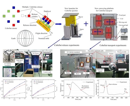
Figure 1 shows the release process of the stacked CubeSats in the deployer. Unlike a single CubeSat in a single deployer with a spring, the multiple CubeSats are stacked in the new deployer. The space platform with a new deployer is launched into a nominal orbit by a single rocket. The proposed CubeSat deployer mainly contains three parts: the pushing actuator, the electromagnetic conveying platform, and the ejection launcher; the pushing mechanism can push the stacked CubeSats to the transfer platform layer by layer; and the electromagnetic conveying platform can transfer the CubeSats to the desired launch windows through two degrees of freedom translation of catching trays. According to the expected separation velocity, the ejection launcher can produce electromagnetic force to put out the CubeSat at the launch windows. Due to the large number of CubeSats, the centroid of the deployer will also change in the release process, and this will also affect the motion and attitude of the rocket. Therefore, the CubeSat conveying route needs to consider the dynamic change of the deployer centroid.
The advantages and merits of the proposed CubeSat deployer are summarized as follows: (1) It has a larger storage capacity. Multiple CubeSats can be tightly stacked and conveyed to the launch window because of the unique electromagnetic conveying platform with adsorption force. (2) It has a higher loading rate. The electromagnetic conveying platform and lacunar are used to convey and release the CubeSats, avoiding a large amount of space occupied by complex mechanical mechanisms. The mass of the traditional deployer is larger than that of the accommodated CubeSats, while the mass of the proposed deployer is smaller than that of all accommodated CubeSats, because multiple CubeSats are stacked tightly and the loading rate is improved effectively. (3) It has multiple and repeatable releases. According to the different weights of the CubeSats, the electromagnetic launcher can adjust the separation speed.

2.2. Electromagnetic Conveying Platform

In the traditional single deployer, the ejection force can affect the motion and attitude of the rocket/space platform. The proposed deployer can reduce the influence of ejection force on the rocket through the reasonable arrangement of release window position of the electromagnetic conveying platform. Figure 2 shows the structure of the electromagnetic conveying platform. There are four release windows and four launchers to ejection four CubeSats at the same time. The thrust directions are opposite to reduce the impact on the rocket. This is to reduce the impact of ejection force on the rocket by designing the release window positions and release direction.
The conveying platform mainly consists of identical drive element cells (fixed part) and catching trays (mover). Each drive element cell contains yokes, tracks, coils, and a wave bead screw in the center. The catching tray mainly includes universal balls and driving units. The structure of the mover element and the drive element cell is shown in Figure 3. Each driving unit is composed of two permanent magnets (PMs).
The catching tray can be reliably attractive to the track because of the adsorption force between the PMs of the mover and the yokes of the drive element cells. The catching tray can be temporarily restrained by the wave bead screw directly above the drive element cell. The universal balls of the mover are on the track, which can guide the tray movement in the x or y direction once the coils in a magnetic field are energized. The four coils of the drive element cell are in the magnetic field between the PMs of the mover and the yoke of the fixed part. When the coils ① and ③ are energized, the electromagnetic force is produced on the mover and overcomes the resistance force of the wave bead screw. And the catching tray can be driven in the y direction until the mover is repositioned by the adjacent wave bed screw of the drive element cell. Similarly, When the coils ② and ④ are energized, the catching tray can move in the x direction.
The advantages and merits of the proposed electromagnetic conveying platform can be summarized as follows: (1) It has high transfer efficiency. The catching trays can move independently and do not interfere with each other. (2) It is had high flexibility and reliability. The catching tray can be reliably attached to the track and be driven at the same time. (3) It had good generality. The movement range of the catching tray can be expanded conveniently due to the modular design of the drive element cells.

2.3. Electromagnetic Launcher

The configuration of the electromagnetic launcher [26] is shown in Figure 4. It mainly consists of the pushing board, coils, and four ejection units. Due to the special configuration of yokes and PMs in the ejection unit, the double magnetic fluxes are formed and superposed in the airgap. The coil is in the airgap magnetic field produced by the PMs. When the coil is energized, the Ampere force is generated, and the pushing board pushes out the CubeSat. Thus, the separation speed of the CubeSat can be directly controlled by regulating the current value. Different from the conventional electromagnetic actuators, the double magnetic circuits of the proposed structure are produced and superimposed at the airgap. The special magnetic circuit structure helps to reduce magnetic saturation and increase the airgap magnetic field. Compared to the conventional one, the proposed electromagnetic launcher has the advantages of a smaller volume and larger thrust density, owing to the improved layout of the PMs and the yokes.

3. Mathematical Models

The electromagnetic forces of the conveying platform and the launcher were established, including the driving force, attractive force, and ejection force. Then the simplified kinetic models of the CubeSats were developed to predict the conveying velocity and the separation speed.

3.1. Driving Force and Attractive Force

We used the equivalent magnetic circuit method to quickly obtain the driving and attractive forces of the driving unit of the conveying platform. The equivalent magnetic circuit of a single driving unit is shown in Figure 5. The magnetomotive force of the PM and reluctance of each region can be expressed as follows:
F p 1 = t p B r u 0 u p ,   r p = t p u 0 u p w p L , R g = g u 0 w p L ,   R l 1 = π 2 u 0 L ,   R l 2 = l y 2 l 2 w c u 0 g L , R y 1 = l y u 0 u y t y 1 L ,   R y 2 = l y + 2 g u 0 u y t y 2 L
where Fp1 is magnetomotive force of the PMs; Rg is airgap magnetic reluctance; Rl1 and Rl2 are the leakage reluctance; Ry1 and Ry2 are the magnetic reluctance of the yokes in Figure 5; Br is the remanence of the PM; u0 is the free space magnetic permeability; uy is the yoke magnetic permeability; and up is the PM relative permeability.
According to Kirchhoff law, the magnetic circuit equation can be expressed as follows:
[ R c 1 r p 2 r p R c ] [ Φ 1 Φ 2 ] = [ 1 0 0 2 ] [ F p 1 F p 1 ]
where Φ1 and Φ2 are the magnetic fluxes. Rc and Rc1 can be calculated by the following:
{ R c = 2 r p + 2 R l 2 R g / ( R l 2 + R g ) + R y 1 + R y 2 R c 1 = R l 1 + r p
From (2), the flux through the airgap of the driving unit can be obtained as follows:
Φ 2 = 2 F p 1 ( R c 1 r p ) / ( R c 1 R c 2 r p 2 )
The attractive force between the single driving unit and the fixed yoke can be calculated as follows:
F = Φ 2 2 u 0 A
where A is the airgap area and can be calculated as follows:
A = L ( w p + g + t p 1 / 2 )
From (4) and Figure 5, the flux density, B, in the airgap region can be expressed as follows:
B = Φ 2 R l 2 ( R l 2 + R g ) = 2 F p 1 ( R c 1 r p ) R l 2 ( R c 1 R c 2 r p 2 ) ( R l 2 + R g )
Considering each coil position, the driving force of the single driving unit can be calculated as follows:
F d = a = 0 m b = 0 n B I ( a , b )
where m and n are the coils’ turns in the vertical and horizontal direction, respectively; and I is the control current in the coils.

3.2. Ejection Force

We used the equivalent magnetic circuit method to quickly obtain the ejection force produced by a single ejection unit. The equivalent double magnetic circuit model of the ejection unit is shown in Figure 6.
The magnetomotive force of the PMs is expressed as follows:
F f p = t f p B r u 0 u p , F p = t m p B r u 0 u p , F b p = t b p B r u 0 u p
The reluctances of each region can be expressed as follows:
r a f = t f p u 0 u p l a p w , R f y = l a p u 0 u y t f y w , R a a = g 2 u 0 t f y w , r p f = t m p u 0 u p l f w , R a f = g u 0 u p l f w , r p b = t m p u 0 u p l b w ,   R a b = g u 0 u p l b w ,   r a b = t b p u 0 u p l a p w ,   R b y = l b y u 0 u y t b y w ,   R y f = l f u 0 u y t y w , R y b = l b u 0 u y t y w
The magnetic circuit equation of the driving unit is calculated through the Kirchhoff law, as follows:
[ R f s + R a R a R a R b s + R a ] [ Φ f Φ b ] = 2 [ F f p + F p F p + F b p ]
where Rfs, Ra, and Rbs can be calculated by the following:
{ R f s = 2 ( R f y + r f p ) + R a a R a = 2 ( R y + r p ) + R g R b s = 2 r b p + R b y
From (11), the flux density in the airgap region can be obtained as follows:
B e = Φ f + Φ b A e = 2 R f s ( F b p + F p ) + R b s ( F f p + F p ) L l ( R f s R b s + R a R f s + R a R b s )
The ejection force can be expressed as follows:
F = N B e L I
where N is the total turns of the coils and L is the movement stroke of the coils.

3.3. Simplified Dynamic Model

The simplified dynamic models of transfer and release are established to analyze the motion characteristics of the CubeSat. The transfer process of the mover between two adjacent drive element cells is shown in Figure 7. Based on the kinetic energy theorem, the movement of the mover can be described by the following:
{ 2 F d x μ b ( 4 F a F s + G ) x μ s F s x = 1 2 M v 1 2 ( 0 < x < l ) 2 F d l μ b ( 4 F a F s + G ) x μ s F s x = 1 2 M v 2 2 - 1 2 M v l 2 ( l < x < s )
where Fs is the spring force of the wave bead screw, M is the mass of the CubeSat, v1 and v2 are the speeds of the mover, μb is the rolling friction coefficient, and μs is the dynamic friction coefficient.
Based on the conservation of momentum and the kinetic energy theorem, the ejection process of the CubeSat from the space platform can be described as follows:
{ F S = 1 2 M v 2 + 1 2 M 1 V 2 M v = M 1 V
Because the mass of the CubeSat is much smaller than that of the space platform, from (16), the separation speed of the CubeSat can be simplified as follows:
v = 2 F M 1 S M 2 + M 1 M
where M is the mass of the CubeSat, M1 is the mass of the space platform, and S is the action stroke of the launcher.

4. Characteristics Analysis

4.1. Magnetic Field Characteristics

The airgap magnetic field characteristics of the conveying platform and the ejection launcher determine the electromagnetic force’s performance. The large magnetic flux leakage can disrupt the normal operation of the CubeSats. Thus, we analyzed the magnetic field distribution in the critical position.
The PMs are arranged on the driving unit of the conveying platform and the ejection unit of the launcher. Therefore, we mainly analyzed the magnetic field distribution of these two units, as shown in Figure 8. The flux densities in the yokes of the two units are not oversaturated. From magnetic lines, the double magnetic circuits are formed and superimposed in the airgap of the ejection unit of the launcher. The flux density in the airgap is shown in Figure 9. The airgap magnetic field of the driving unit is uneven due to the single-sided arrangement of PMs. The average flux density of the airgap is about 0.277T. The position of the coils close to the PMs achieves a high driving force, owing to high flux density, which can improve the drive efficiency. The airgap magnetic field of the ejection unit is uniform due to the double-sided arrangement of PMs. The average flux density of the airgap is about 0.437T.
To evaluate the effect of the magnetic flux leakage from the transit platform and ejection launcher on the CubeSat, we examined the field distribution of the driving unit position ① and the ejection unit position ②. The two positions, ① and ②, are the regions closest to the outermost edge of the CubeSat, about 20 mm. Figure 10 shows the flux density of positions ① and ②. The magnetic field of position ①, close to the center of the two PMs, is maximum due to magnetic saturation of the main yoke, as shown in Figure 8a. The magnetic field of position ②, close to the center of the airgap, is maximum due to high magnetic leakage, as shown in in Figure 8b. The maximum values of the inspection positions ① and ② are 3.78 mT and 22.7 mT, respectively, indicating that the magnetic leakage does not cause damage to the normal work of the CubeSats.

4.2. Separation Characteristics of Angular Speed

The excessive separation angular speed can cause the released CubeSat instability, and the low angular speed is expected for the released CubeSats [27,28,29]. We analyzed the separation characteristics of angular speed for 1U and 3U CubeSats. In order to make the simulation close to the practice, we set the centroids of the CubeSat to deviate by 0.5 mm in the XYZ direction. Figure 11 shows the angular speed of 1U CubeSat of 1 kg. Due to the deviated center of mass, the angular velocity gradually increases with the actuation of the launcher. When the CubeSat leaves the tray, the angular velocity decreases instantaneously. The separation angular speed in the x, y, and z directions are 0.7°/s, 2.2°/s, and 1.2°/s, respectively. Figure 12 shows the angular speed of 3U CubeSat. Due to the deviated center of mass, the angular velocity in the y and z directions gradually increases with the actuation of the launcher. The angular velocity in the x direction is close to zero. When the CubeSat leaves the tray, the CubeSat angular velocity in the y and z directions further increases. With the length of the 3U CubeSat larger than that of the 1U CubeSat, the angular speed is reduced. The separation angular speeds in the x and y directions are 0.42°/s and 0.43°/s, respectively. The simulation results are less than 3°/s of the requirement value of the CubeSat, indicating that the developer design is reasonable.

5. Experiment Investigation

The principal prototypes of the electromagnetic conveying platform and the launcher were developed, as shown in Figure 13 and Figure 14. Figure 13 shows the mover and drive element cells of the conveying platform. In order to facilitate the test of the characteristics under different working conditions, only two adjacent drive element cells were adopted. Figure 14 shows the stator and mover of the launcher. Firstly, the magnetic field distribution at key positions and force characteristics were tested for the conveying platform and the launcher. Then the motion characteristics of the conveying platform and the separation speed of the CubeSat were investigated via experiments.

5.1. Magnetic Field Leakage

Figure 15 shows the measurement of the magnetic field at the key position. The Gauss meter is used to record the magnetic flux density. The XYZ stage can change the relative position between the ejection unit and the probe. The XYZ stage and Z stage are applied to change the relative position of the driving unit and the probe.
The airgap center flux density of the ejection unit and the driving unit is shown in Figure 16. The finite element method (FEM) results are larger than the experimental results. The reason is that the key parameters in the FEM soft are not completely consistent with the actual values. The airgap flux density of the ejection unit is large and uniform due to unique double magnetic circuits. The average flux density at the airgap center of the ejection unit is about 0.424T. Because of the single-sided arrangement of the permanent magnet, the airgap magnetic density at the center of the driving unit is large and decreases to both sides. The average flux density at the airgap center of the driving unit is about 0.23T.
To evaluate the influence of magnetic field distribution on the CubeSat. Figure 17 illustrates magnetic field leakage at the key position close to the CubeSat. Due to the magnetic field enhancement of the double magnetic circuit, the magnetic flux leakage of the launcher is larger than that of the conveying platform. The magnetic field decreases from the center of the launcher to the edge region, as shown in Figure 17a. Due to the mutual superposition of the flux density leakage of the four ejection units, the magnetic field at the axis position of the launcher is the largest, at 20.17 mT. The flux density close to the edge position is the weakest, at the 5.2 mT. Figure 17b shows that the central region of the mover is the weakest, at 0.56 mT. The flux density leakage at the center region of the driving unit is about 1.41 mT. The maximum leakage magnetic density of the mover is about 1.62 mT. The measurement results show that the magnetic flux density leakage of the launcher and the conveying platform is small and does not damage the normal operation of the CubeSats.

5.2. Electromagnetic Force Characteristics

Figure 18 shows the experimental measurements of the ejection force, attractive force, and driving force. In Figure 18a, the Z stage can change the relative position of the mover and stator of the launcher in the vertical direction. The force meter is applied to record the thrust of the ejection force produced by energized coils. In Figure 18b, the XZ stage is applied to adjust the relative position of the mover and the fixed part of the conveying platform. The force meter is fixed vertically to measure the attractive force and is mounted horizontally to obtain the driving force.
The measurement results of ejection force are shown in Figure 19. The theoretical results agree well with the experimental results, meaning that the electromagnetic force model obtained from the equivalent magnetic circuit method is reliable. With the enhancement of the current for high ejection force, the error between the theoretical results and experimental results increases. The reason is that the armature field produced by energized current could affect the distribution of the original magnetic field generated by the PMs, especially under a higher current density. The mathematical model did not consider the influence of the armature reaction on the electromagnetic force. The FEM results also match the experimental results, indicating that the magnetic field characteristics results are feasible. Owing to the uniform distribution of the airgap magnetic field, the ejection force output is stable, and the fluctuation is small under a low current. Under a high current density, the theoretical results are larger than the experimental results. The reason is that the armature reaction is affected not only by the current density but also by the position of the coil in the airgap. The armature field interferes with the original permanent magnetic field acting on the coil, which is not taken into account in the mathematical model. The ejection force density and driving force density are achieved due to high magnetic field and magnetic saturation mitigation.
The test results of attractive force and driving force are shown in Figure 20. The results show that the large attractive force between the mover and the fixed part of the conveying platform is achieved. However, there is an error between the FEM result and the experimental result. The reason is that some magnetic field leakage is regarded as airgap magnetic field by using FEM. Figure 20b shows that the driving force gradually decreases due to the uneven magnetic field distribution at the end of the driving unit. The fluctuation of the driving force is about 20%. In the next section, the motion characteristics of the mover are investigated under the large attractive force and the fluctuating driving force.

5.3. Conveying Characteristics

The experiments of the transfer motion between the two adjacent drive element cells are shown in Figure 21. To verify the dynamic model of the mover, the two drive elementary cells are fixed in the horizontal direction. Under this condition, the gravity of the CubeSat increases friction between the mover and the track. To highlight the attractive performance, the two drive elementary cells are mounted vertically. Under this condition, the gravity of the CubeSat is regarded as the interference force acting on the CubeSat. The mover with a simulated 1U CubeSat with a mass of 1 kg is attached to the track. The gravitational force acting on the CubeSat can be regarded as an external disturbing force. The whole transfer process of the CubeSat can be recorded by a high-speed camera.
Figure 22 shows the results of motion speed versus position in the horizontal direction. The theoretical results are larger than those of experiments because the friction coefficients in the dynamic model are not completely consistent with the practical value. The results show that the theoretical results effectively describe the motion trend of the mover, meaning that the dynamic model is reliable. Thus, the simplified dynamic model can quickly predict the transfer speed of the mover. Figure 23 shows the experimental results of the motion position versus time. The distance between the two adjacent element cells is about 12 cm. It takes 0.409 s for the mover to transfer to the adjacent elementary cell. Therefore, the conveying platform achieves efficient transport. Figure 24 shows the speed of the mover versus time. The mover transfers smoothly without obvious fluctuations. Under the current of 5A, the maximum speed of the mover is 0.56 m/s. The acceleration of the mover versus the time is shown in Figure 25. The maximum acceleration is 11.7 m/s2. Due to the uneven contact surface between the track and the universal balls, the acceleration fluctuates during the mover-deceleration process.

5.4. Ejection Experiment

The release speed of the CubeSats was tested by a gravity compensation experiment, as shown in Figure 26. The three Cubes with a mass of 1 kg were selected to simulate the CubeSats with a mass of 1 kg or 3 kg. The two ends of the rope are respectively connected with the CubeSat and the counterweight. The CubeSat is released downward by the launcher to realize gravity compensation through the counterweight. The separation speeds of the CubeSats can be obtained by a high-speed camera. Because the deployer is mounted on the frame in the experiment, the separation speed of the CubeSat can be simplified as follows:
v = 2 F S / m
where S is the action stroke of the launcher and m is the mass of the simulated CubeSat.
The experiment results of separation speeds are shown in Figure 27. The theoretical results are consistent with the experimental results, and the errors are less than 11%, thus indicating that the established model is credible. There are two main reasons for the error between the theoretical results and experiment results: (1) The higher the current, the higher the separation velocity, and the more energy loss due to contact collision during the CubeSat release. The collision causes the reduction of separation velocity, which is not taken into account by the simplified kinetic model. (2) Under a high current density, the armature reaction is more obvious. The armature magnetic field seriously weakens the original permanent magnetic field and causes the ejection force to be reduced. The electromagnetic force model does not take the influence of armature reaction into account. Under the current of 0.5 A–2.5 A, separation speeds of 1U and 3U CubeSats are 0.67 m/s–1.42 m/s and 0.4 m/s–0.85 m/s. Thus, the proposed launcher achieves a wider separation-speed adjustment range.
The proposed deployer is superior to the traditional one in terms of capacity, volume, mass, and ejection performance, owing to the high-performance electromagnetic actuators. However, objectively, the reliability of the proposed deployer is lower than that of the traditional one, because one of the CubeSats is stuck in the transport process, thus affecting the conveying routes of all CubeSats. The transport efficiency is reduced, and even the release fails. We will further improve the deployer’s reliability in future studies.

6. Conclusions

A new deployer with an electromagnetic transfer and launch was proposed to achieve multiple stacked CubeSats release in orbit. Different from the traditional ejection method of compression springs, two key technologies of electromagnetic transfer and ejection were mainly investigated in this study. We used the equivalent magnetic circuit method to quickly build the electromagnetic force models, including the attractive force, driving force, and ejection force. The simplified dynamics models of transfer and ejection were obtained through the kinetic energy theorem. The principal prototypes of the conveying platform and the launcher were developed to test magnetic field distribution, electromagnetic force, motion characteristics, and separation speed of the CubeSats. The main conclusions can be obtained as follows:
  • The results of the theoretical force models are consistent with the experimental results. The transfer velocity and separation speed obtained from the kinetic models agree with the experimental results. The developed mathematical models can be used to rapidly analyze electromagnetic force and motion characteristics in engineering.
  • Even under the constant external interference force, the mover of the electromagnetic conveying platform can still be reliably adsorbed on the track and realize fast transfer. The maximum movement speed of the mover is 0.56 m/s. The maximum drive acceleration is 11.7 m/s2. The high transfer efficiency is achieved owing to high driving force density.
  • High ejection force density is achieved by the proposed launcher with double magnetic circuits. The magnetic field leakage is small and does not interfere with the work of the CubeSat. The experimental results show the launcher can effectively adjust the separation velocity according to the mass of the CubeSat.
The proposed electromagnetic transfer and ejection technology are expected to be applied to the deployer for achieving larger-scale CubeSat release in orbit. We will reduce the separation angular velocity of the released CubeSats by optimizing the structural parameters of the deployer and further improve the reliability in future studies.

Author Contributions

Conceptualization, Y.Z. and H.Y.; methodology, Y.Z. and X.M.; software, Y.Z. and X.M.; validation, X.M. and Y.Z.; formal analysis, X.Y. and X.M.; investigation, X.Y. and X.M.; resources, H.Y.; data curation, X.Y. and F.Y.; writing—original draft preparation, Y.Z.; writing—review and editing, X.Y. and Y.Z.; visualization, X.Y. and F.Y.; supervision, F.Y. and H.Y.; project administration, H.Y. and F.Y.; funding acquisition, H.Y. and F.Y. All authors have read and agreed to the published version of the manuscript.

Funding

This research was funded by the National Natural Science Foundation of China (52075118).

Data Availability Statement

Not applicable.

Acknowledgments

The author would like to thank the editors, academic editor, and the reviewers for their valuable comments and constructive suggestions that helped to improve the paper significantly.

Conflicts of Interest

The authors declare no conflict of interest.

References

  1. Liu, S.; Theoharis, P.I.; Raad, R.; Tubbal, F.; Theoharis, A.; Iranmanesh, S.; Abulgasem, S.; Khan, M.U.A.; Matekovits, L. A Survey on CubeSat Missions and Their Antenna Designs. Electronic 2022, 11, 2021. [Google Scholar] [CrossRef]
  2. Bogomolov, A.V.; Bogomolov, V.V.; Iyudin, A.F.; Eremeev, V.E.; Kalegaev, V.V.; Myagkova, I.N.; Osedlo, V.I.; Petrov, V.L.; Peretjat’ko, O.Y.; Prokhorov, M.I.; et al. Space Weather Effects from Observations by Moscow University Cubesat Constellation. Universe 2022, 8, 282. [Google Scholar] [CrossRef]
  3. Nosseir, A.E.S.; Cervone, A.; Pasini, A. Modular Impulsive Green Monopropellant Propulsion System (MIMPS-G): For CubeSats in LEO and to the Moon. Aerospace 2021, 8, 169. [Google Scholar] [CrossRef]
  4. Fernandez, L.; Sobrino, M.; Ruiz-de-Azua, J.A.; Calveras, A.; Camps, A. Design of a Deployable Helix Antenna at L-Band for a 1-Unit CubeSat: From Theoretical Analysis to Flight Model Results. Sensors 2022, 22, 3633. [Google Scholar] [CrossRef] [PubMed]
  5. Azami, M.H.B.; Orger, N.C.; Schulz, V.H.; Oshiro, T.; Cho, M. Earth Observation Mission of a 6U CubeSat with a 5-Meter Resolution for Wildfire Image Classification Using Convolution Neural Network Approach. Remote Sens. 2022, 14, 1874. [Google Scholar] [CrossRef]
  6. Liu, X.; Xing, F.; Fan, S.; You, Z. A Compressed and High-Accuracy Star Tracker with On-Orbit Deployable Baffle for Remote Sensing CubeSats. Remote Sens. 2021, 13, 2503. [Google Scholar] [CrossRef]
  7. Pellegrino, A.; Pancalli, M.G.; Gianfermo, A.; Marzioli, P.; Curianò, F.; Angeletti, F.; Piergentili, F.; Santoni, F. HORUS: Multispectral and Multiangle CubeSat Mission Targeting Sub-Kilometer Remote Sensing Applications. Remote Sens. 2021, 13, 2399. [Google Scholar] [CrossRef]
  8. Heidt, M.H.; Puig-Suari, P.J.; Augustus, P.; Nakasuka, S.; Twiggs, R. CubeSat: A new generation of picosatellite for education and industry low-cost space experimentation. In Proceedings of the Thirteenth Annual AIAA/USU Small Satellite Conference, Logan, Utah, 21–24 August 2000. [Google Scholar]
  9. Lee, S.; Clemens, N.; Puig-Suari, J.; Twiggs, B. Cal Poly Coordination of Multiple CubeSats on the DNEPR Launch Vehicle. In Proceedings of the 18th Annual AIAA/USU Conference on Small Satellites, Carefree, AZ, USA, 9–11 August 2004. [Google Scholar]
  10. Ashida, H.; Fujihashi, K.; Inagawa, S.; Miura, Y.; Omagari, K.; Miyashita, N.; Matunaga, S.; Toizumi, T.; Kataoka, J.; Kawai, N.; et al. Design of Tokyo Tech nano-satellite Cute-1.7+APD II and its operation. Acta Astronaut. 2010, 66, 1412–1424. [Google Scholar] [CrossRef]
  11. Hevner, R. Lessons learned flight validating an innovative Canisterized Satellite Dispenser. In Proceedings of the IEEE Aerospace Conference, Big Sky, MT, USA, 1–8 May 2014; pp. 1–14. [Google Scholar]
  12. Dobrowolski, M.; Tokarz, M.; Borys, M. DRAGON—8U Nanosatellite Orbital Deployer. In Proceedings of the 42nd Aerospace Mechanisms Symposium, Baltimore, MD, USA, 14–16 May 2014. [Google Scholar]
  13. Zhao, X.; Zhao, C.; Li, J.; Guan, Y.; Chen, S.; Zhang, L. Research on Design, Simulation, and Experiment of Separation Mechanism for Micro-Nano Satellites. Appl. Sci. 2022, 12, 5997. [Google Scholar] [CrossRef]
  14. Akagi, H.; Takata, M.; Watanabe, H.; Oikawa, K. Kibo’s contribution to broadening the possibilities for Micro/Nano-Satellite. In Proceedings of the SpaceOps 2016 Conferences, Daejeo, Korea, 16–20 May 2016; pp. 1–8. [Google Scholar]
  15. Nason, I.; Puig-Suari, J.; Twiggs, R. Development of a family of picosatellite deployers based on the CubeSat standard. In Proceedings of the IEEE Conference on Aerospace, Big Sky, MT, USA, 9–16 March 2002; pp. 457–464. [Google Scholar]
  16. Heidt, H.; Suari, J.P.; Moore, A.S.; Nakasuka, S.; Twiggs, R.J. CubeSat: A new generation of picosatellite for education and industry low-cost space experimentation. In Proceedings of the Fourteenth Annual AIAA/USU Small Satellite Conference, Berlin, Germany, 2–6 April 2001; pp. 1–19. [Google Scholar]
  17. Jordi, P.S.; Turner, C.; Ahlgren, W. Development of the Standard CubeSat Deployer and a CubeSat Class PicoSatellite. In Proceedings of the Aerospace Conference, Big Sky, MT, USA, 10–17 March 2001; Volume 1, pp. 347–353. [Google Scholar]
  18. Xie, C.X. Research on Design Analysis Method and Key Technologies of Pico-Satellite Separation Mechanism; Zhejiang University: Hangzhou, China, 2014. [Google Scholar]
  19. Ali, M.R. Design and Implementation of Ground Support Equipment for Characterizing Performance of XPOD and CNAPS & Thermal Analysis of CNAPS Pressure Regulator Valve; University of Toronto: Toronto, ON, Canada, 2009. [Google Scholar]
  20. Pranajaya, F.M.; Zee, R.E. Generic Nanosatellite Bus for Responsive Mission. In Proceedings of the 5th Responsive Space Conference, Los Angeles, CA, USA, 23–26 April 2007. [Google Scholar]
  21. Pranajaya, F.M.; Zee, R.E. The Generic Nanosatellite Bus: From Space Astronomy to Formation Flying Demo to Responsive Space. In Proceedings of the International Conference on Advances in Satellite and Space Communications, Colmar, France, 20–25 July 2009; pp. 134–140. [Google Scholar]
  22. Fujihashi, K.; Omagari, K.; Fujiwara, K.; Konda, Y.; Maeno, M.; Tanaka, Y.; Ueno, T.; Ashida, H.; Nishida, J.; Hagiwara, Y.; et al. Development of Tokyo Tech Nano-Satellite Cute-1.7+APD II. In Proceedings of the 17th Workshop on JAXA Astrodynamics and Flight Mechanics, Sagamihara, Japan, 28 March 2007; Volume 107, pp. 33–38. [Google Scholar]
  23. Zhang, C.; Huang, X.; Yang, M.; Chen, S.; Yang, G. Design of a Long Stroke Nanopositioning Stage with Self-Damping Actuator and Flexure Guide. IEEE Trans. Ind. Electron. 2022, 69, 10417–10427. [Google Scholar] [CrossRef]
  24. Zhang, Z.; Luo, M.; Zhou, H.; Duan, J.-A. Design and Analysis of a Novel Two-Degree-of-Freedom Voice Coil Motor. IEEE/ASME Trans. Mechatron. 2019, 24, 2908–2918. [Google Scholar] [CrossRef]
  25. Zhu, H.; Teo, T.J.; Pang, C.K. Design and Modeling of a Six-Degree-of-Freedom Magnetically Levitated Positioner Using Square Coils and 1-D Halbach Arrays. IEEE Trans. Ind. Electron. 2017, 64, 440–450. [Google Scholar] [CrossRef]
  26. Zhao, Y.; Yue, H.; Yang, F.; Zhu, J. A High Thrust Density Voice Coil Actuator with a New Structure of Double Magnetic Circuits for CubeSat Deployers. IEEE Trans. Ind. Electron. 2022, 69, 13305–13315. [Google Scholar] [CrossRef]
  27. Glushchenkov, V.A.; Yusupov, R.Y. Controlled separation of nanosatellites by means of the pulsed magnetic field. Russ. Aeronaut 2017, 60, 1–8. [Google Scholar] [CrossRef]
  28. Belokonov, I.V.; Timbai, I.A.; Nikolaev, P.N. Analysis and Synthesis of Motion of Aerodynamically Stabilized Nanosatellites of the CubeSat Design. Gyroscopy Navig. 2018, 9, 287–300. [Google Scholar] [CrossRef]
  29. Filonin, O.V.; Belokonov, I.V.; Gimranov, Z.I. Small-Size Automatic System for the Controllable Launch of Nanosatellites on a Desired Trajectory. Russ. Aeronaut. 2019, 62, 184–191. [Google Scholar]
Figure 1. Separation process of the stacked CubeSats in the new deployer.
Remotesensing 14 04205 g001
Figure 2. Structure of the electromagnetic conveying platform.
Remotesensing 14 04205 g002
Figure 3. Configuration of the drive element cell and the mover.
Remotesensing 14 04205 g003
Figure 4. Configuration of the electromagnetic launcher.
Remotesensing 14 04205 g004
Figure 5. The equivalent magnetic circuit of the driving unit.
Remotesensing 14 04205 g005
Figure 6. The equivalent magnetic circuit of the ejection unit.
Remotesensing 14 04205 g006
Figure 7. Transfer process between two adjacent drive element cells.
Remotesensing 14 04205 g007
Figure 8. Flux density distribution of the driving unit and ejection unit: (a) driving unit of the conveying platform and (b) ejection unit of the launcher.
Remotesensing 14 04205 g008
Figure 9. Flux density in the airgap region: (a) driving unit of the conveying platform and (b) ejection unit of the launcher.
Remotesensing 14 04205 g009
Figure 10. Flux density at the key positions close to the CubeSat: (a) driving unit of the conveying platform and (b) ejection unit of the launcher.
Remotesensing 14 04205 g010
Figure 11. Separation angular speed of the 1U CubeSat.
Remotesensing 14 04205 g011
Figure 12. Separation angular speed of the 3U CubeSat.
Remotesensing 14 04205 g012
Figure 13. Prototype of the conveying platform.
Remotesensing 14 04205 g013
Figure 14. Prototype of the launcher.
Remotesensing 14 04205 g014
Figure 15. Magnetic-field-leakage measurement.
Remotesensing 14 04205 g015
Figure 16. Magnetic field in the airgap center: (a) ejection unit and (b) driving unit.
Remotesensing 14 04205 g016
Figure 17. Magnetic field leakage at the key position close to the CubeSat: (a) ejection unit of the launcher and (b) driving unit of the conveying platform.
Remotesensing 14 04205 g017
Figure 18. Measurement of electromagnetic force: (a) ejection force of the launcher; (b) attractive force and driving force of the conveying platform.
Remotesensing 14 04205 g018
Figure 19. Ejection force of the launcher: (a) ejection force versus current and (b) ejection force versus position.
Remotesensing 14 04205 g019
Figure 20. Electromagnetic force of the conveying platform: (a) attractive force and (b) driving force.
Remotesensing 14 04205 g020
Figure 21. Measurement of motion process.
Remotesensing 14 04205 g021
Figure 22. Speed comparison of the theoretical results and experimental results.
Remotesensing 14 04205 g022
Figure 23. Position of the mover versus time.
Remotesensing 14 04205 g023
Figure 24. Velocity of the mover versus time.
Remotesensing 14 04205 g024
Figure 25. Acceleration of the mover versus time.
Remotesensing 14 04205 g025
Figure 26. Ejection test of the launcher.
Remotesensing 14 04205 g026
Figure 27. Separation speed: (a) 1U CubeSat and (b) 3U CubeSat.
Remotesensing 14 04205 g027
Publisher’s Note: MDPI stays neutral with regard to jurisdictional claims in published maps and institutional affiliations.

