

3D Printing for Repair: An Approach for Enhancing Repair

Abstract
:1. Introduction
2. Materials and Methods
2.1. Establishing a Framework for 3DPfR
2.2. Identifying Factors for Successful Repair
3. Results
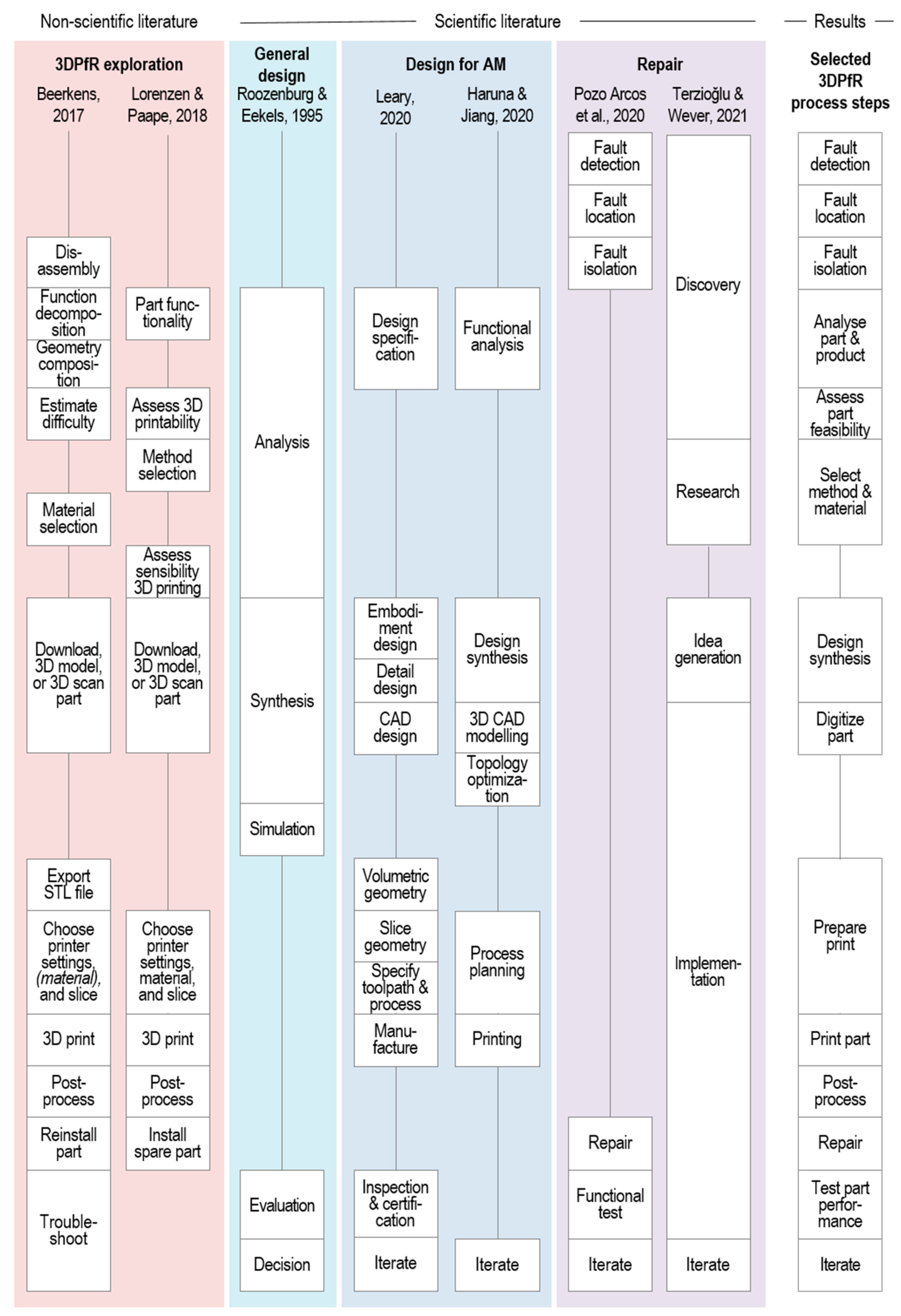
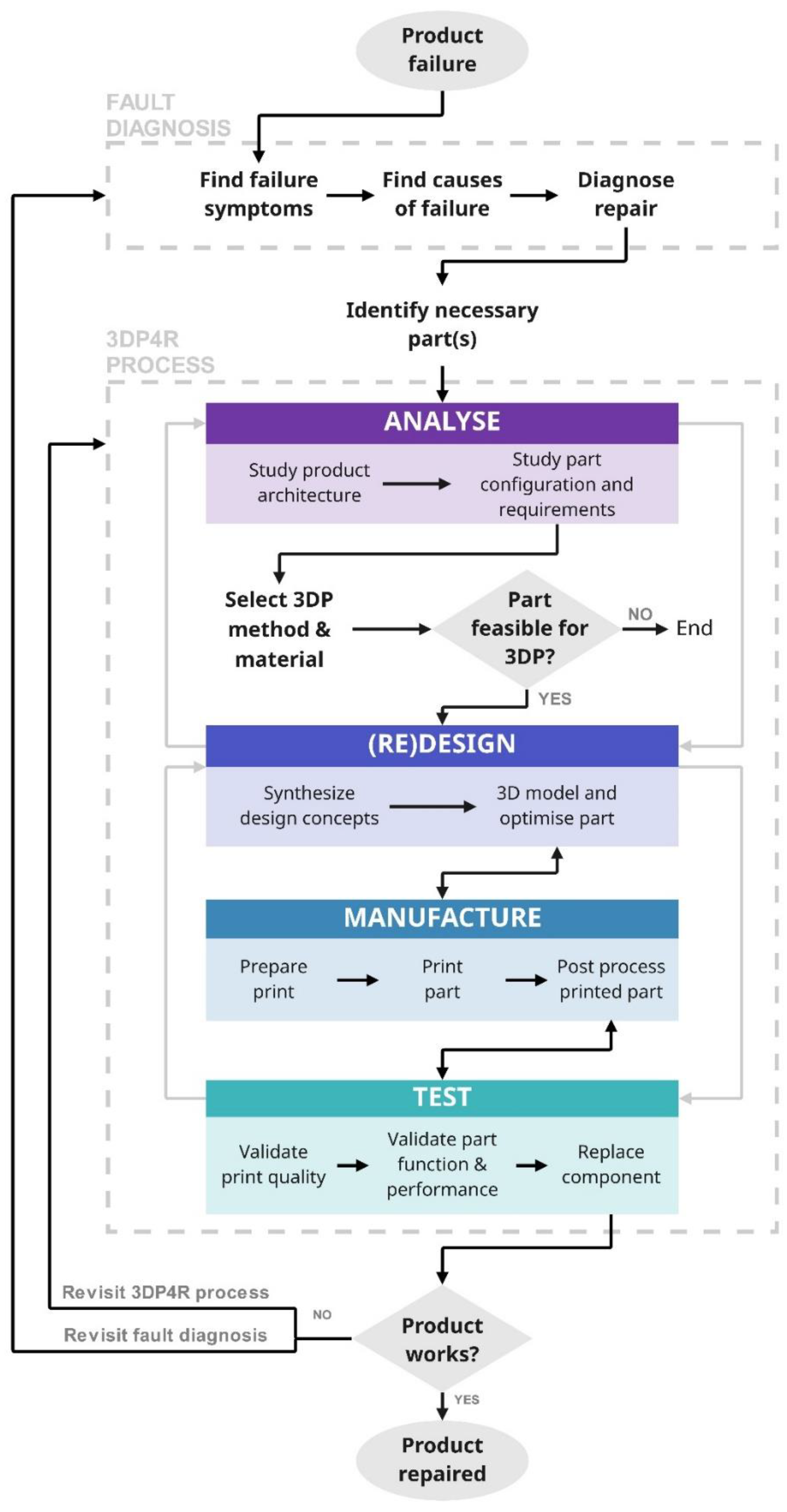
3.1. The 3DPfR Framework
3.1.1. Literature Review
Selected Steps That Appeared in All Frameworks

Selected Steps That Appeared in Some Frameworks
Steps That Were Not Selected
Additional Insights
3.1.2. Experimental Study
Process Changes
Process Validation and Clarification
3.2. Factors for Successful Repair
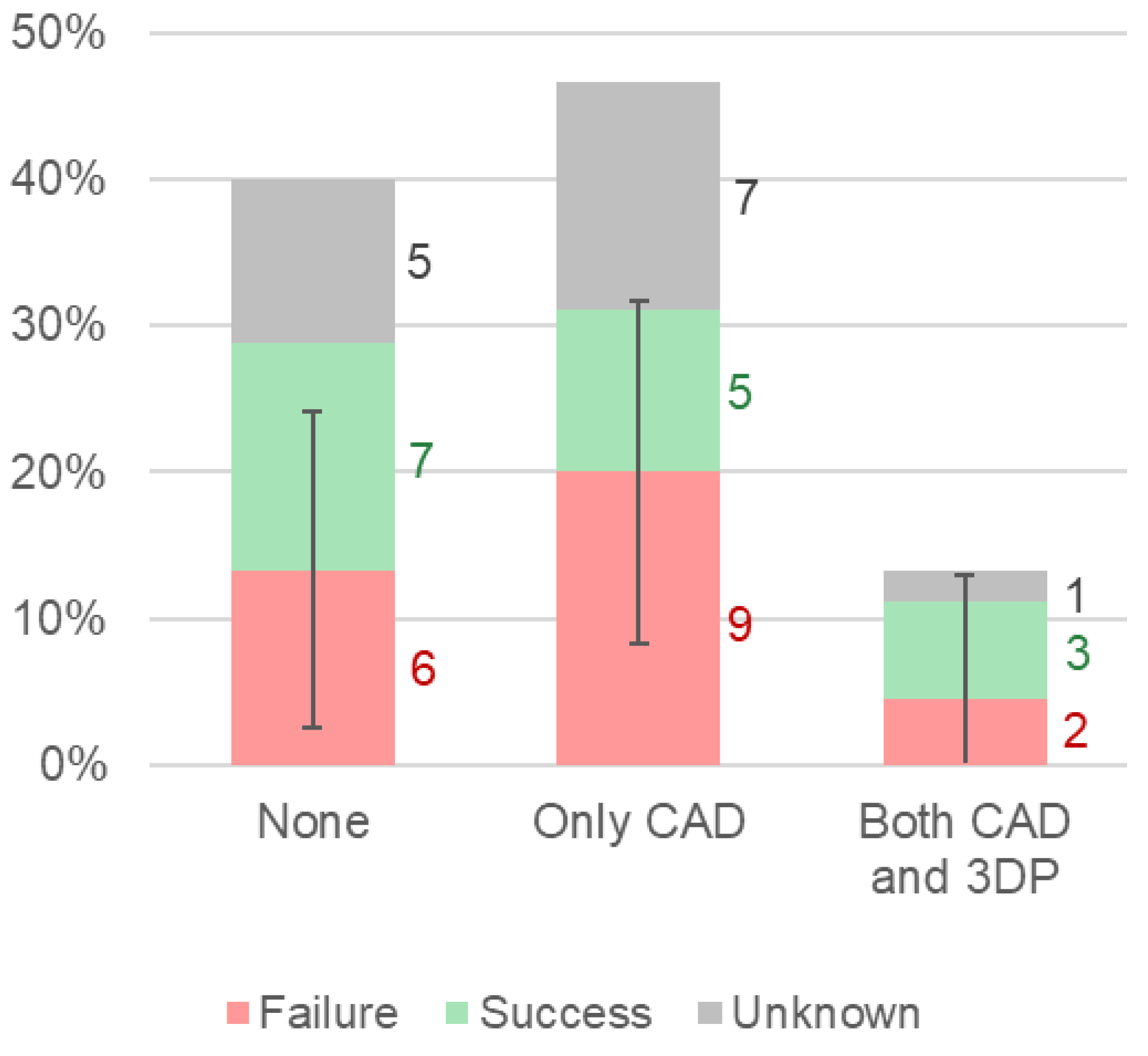
3.2.1. Previous Experience
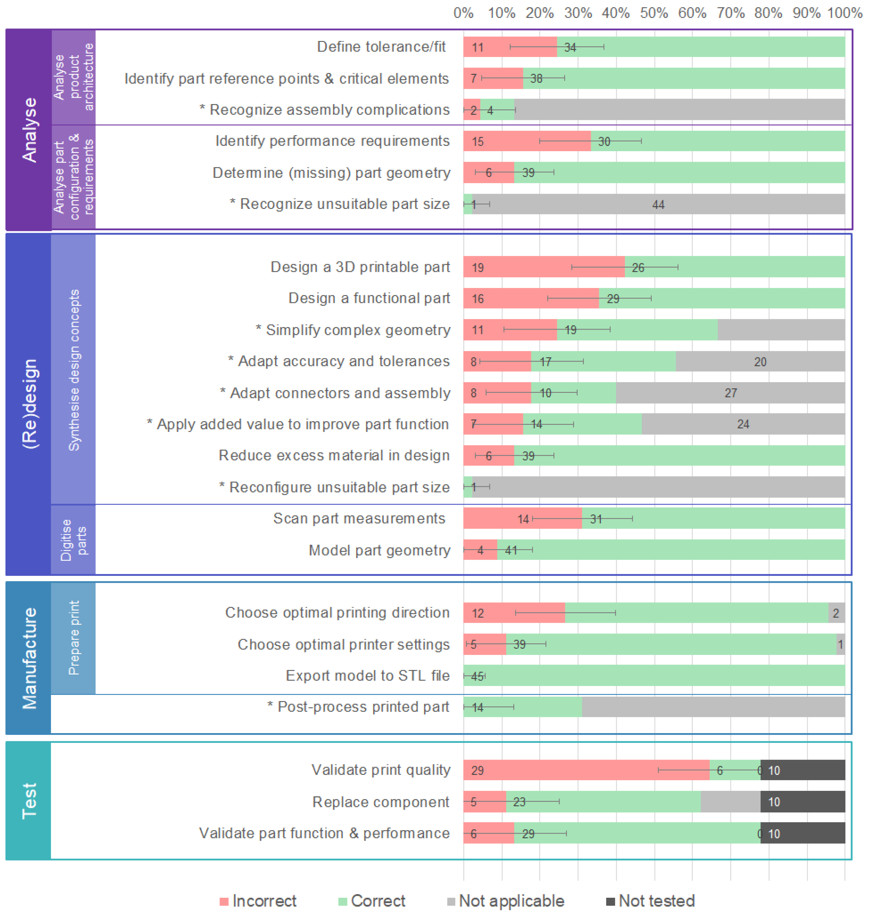
3.2.2. Process Implementation
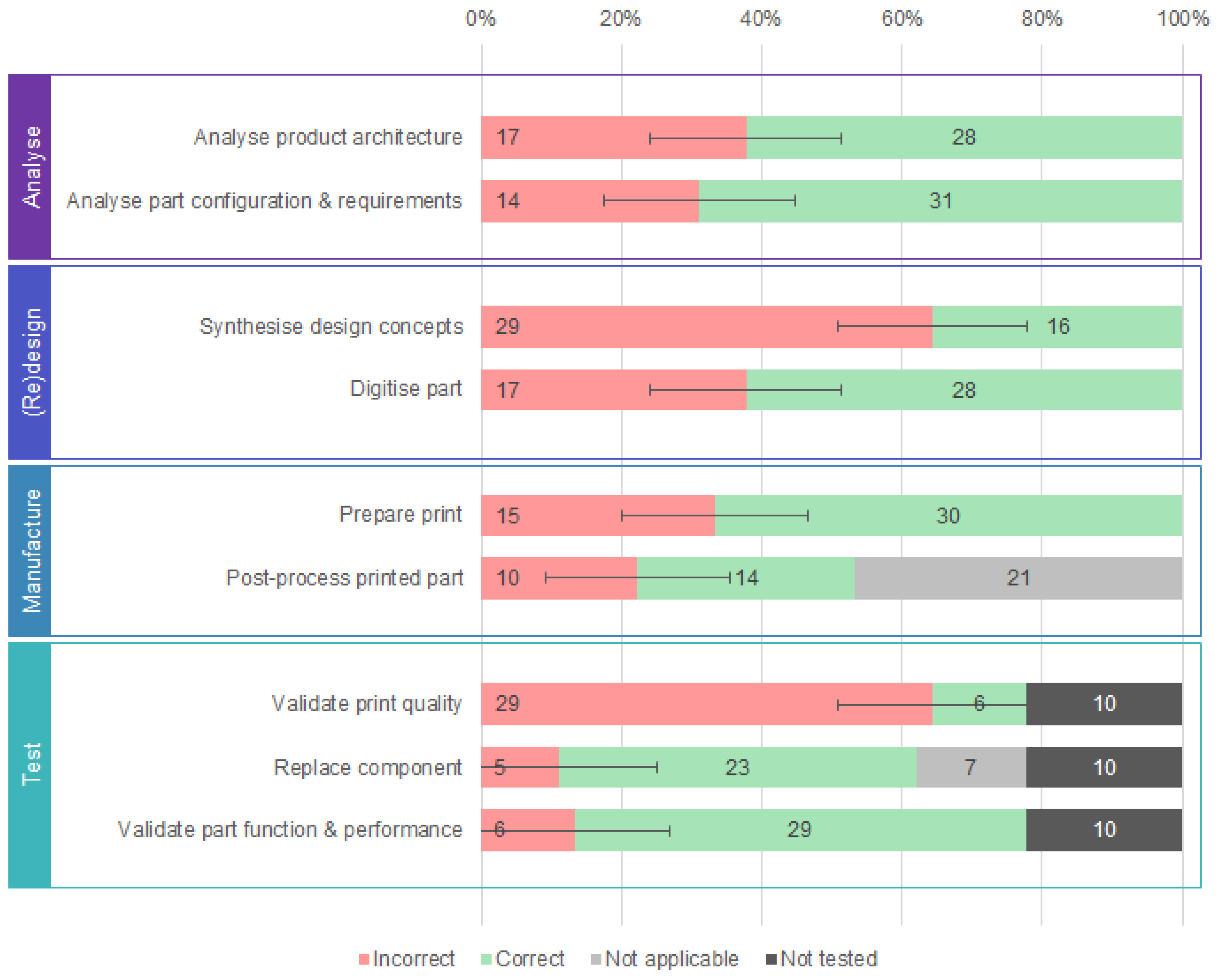
Overall Process Implementation
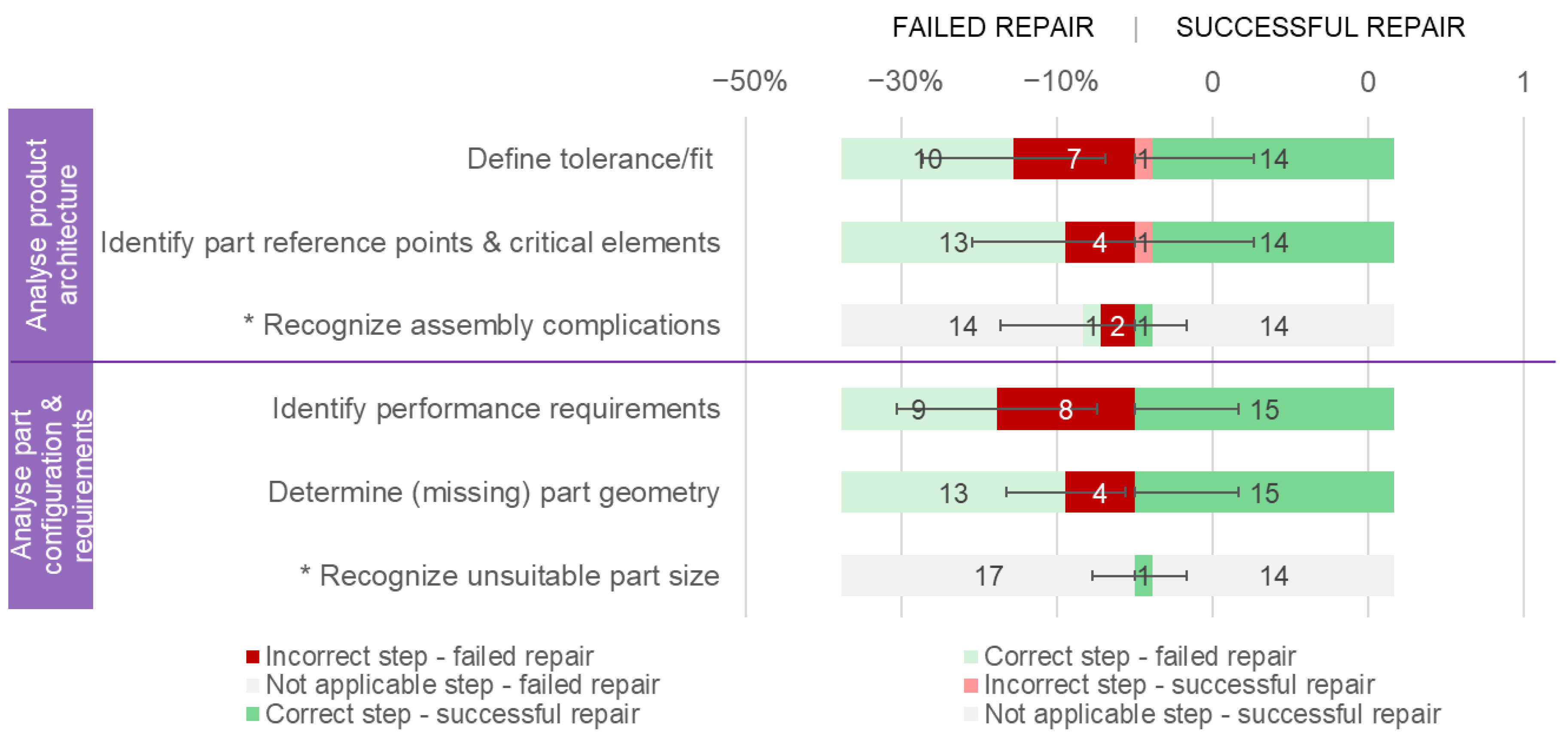
Analyse Phase
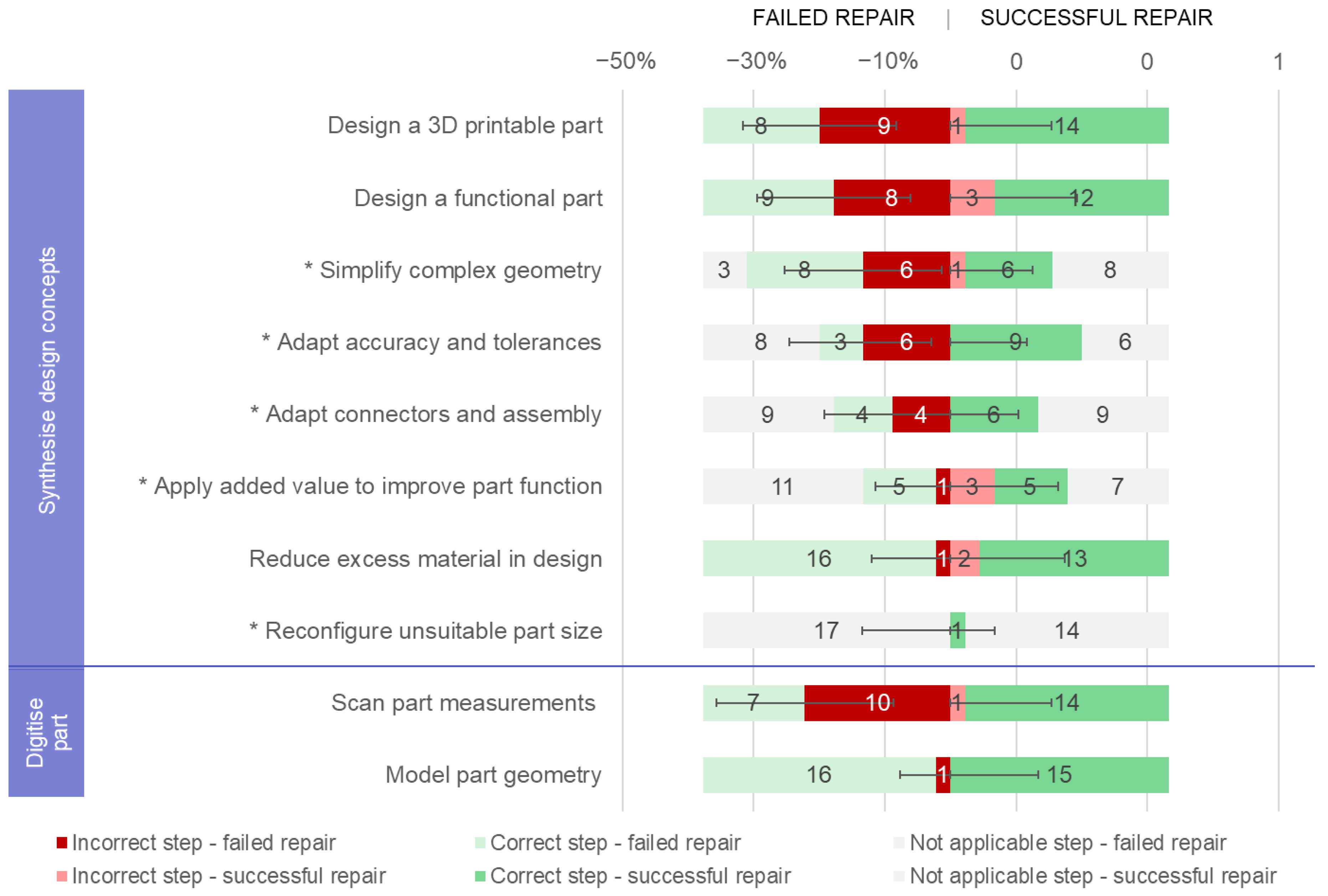
(Re)design Phase
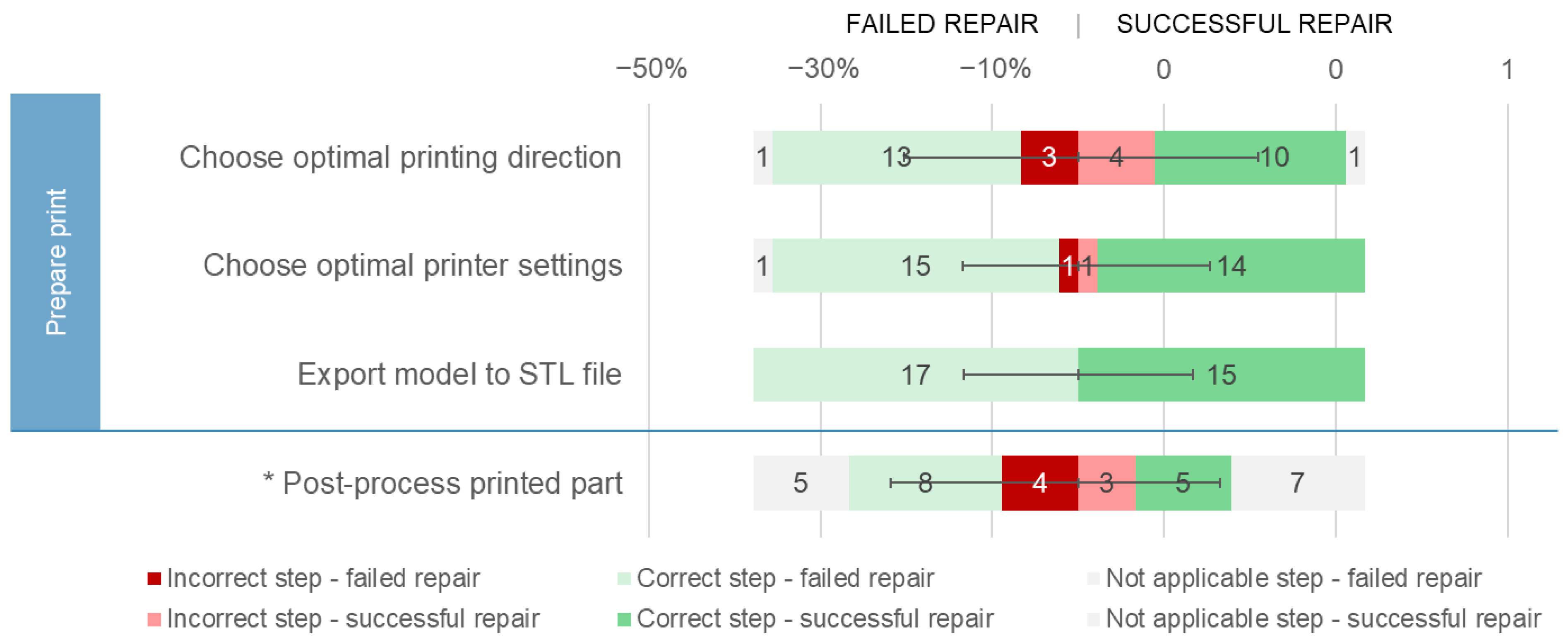
Manufacture Phase
3.2.3. Part Complexity
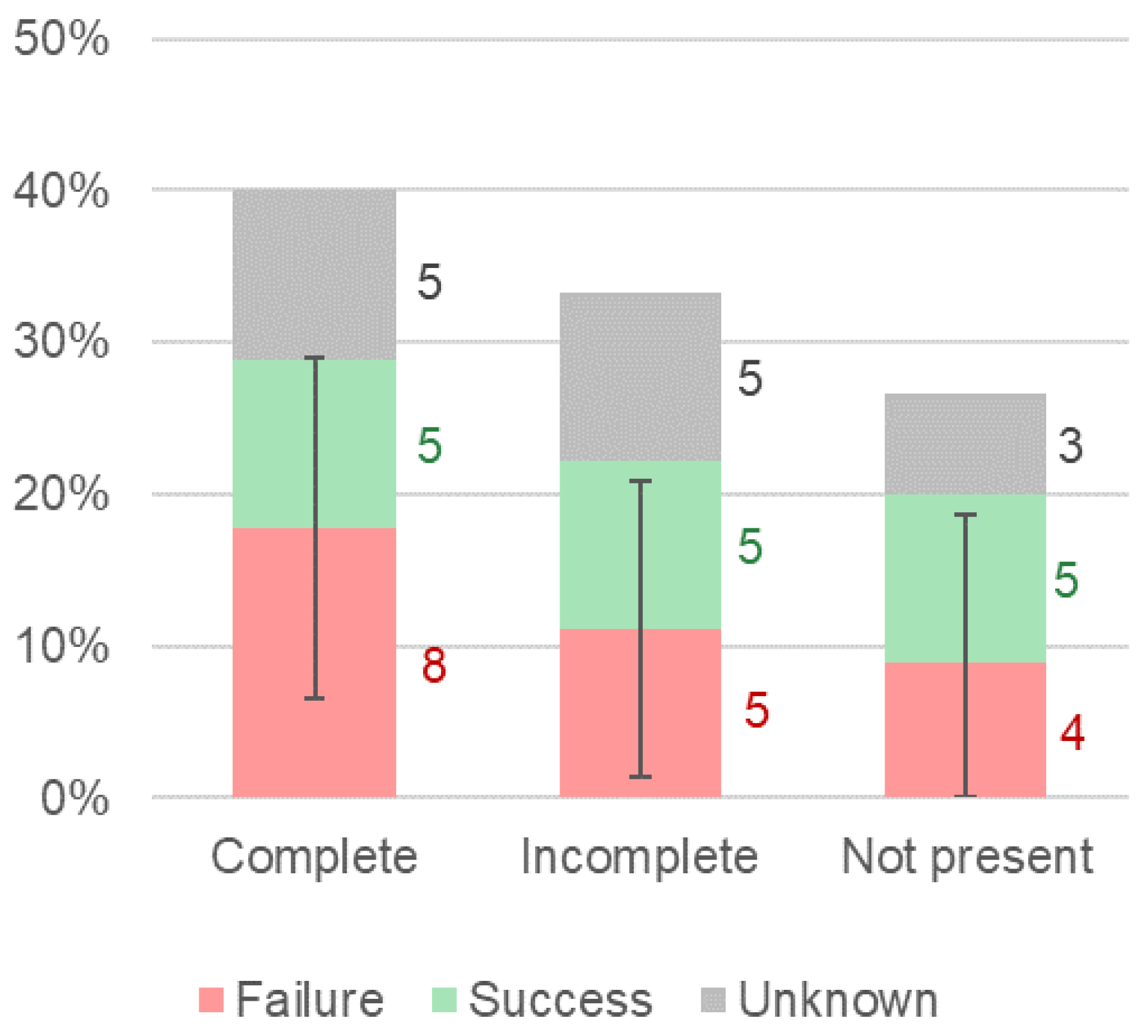
Part Geometry Completeness
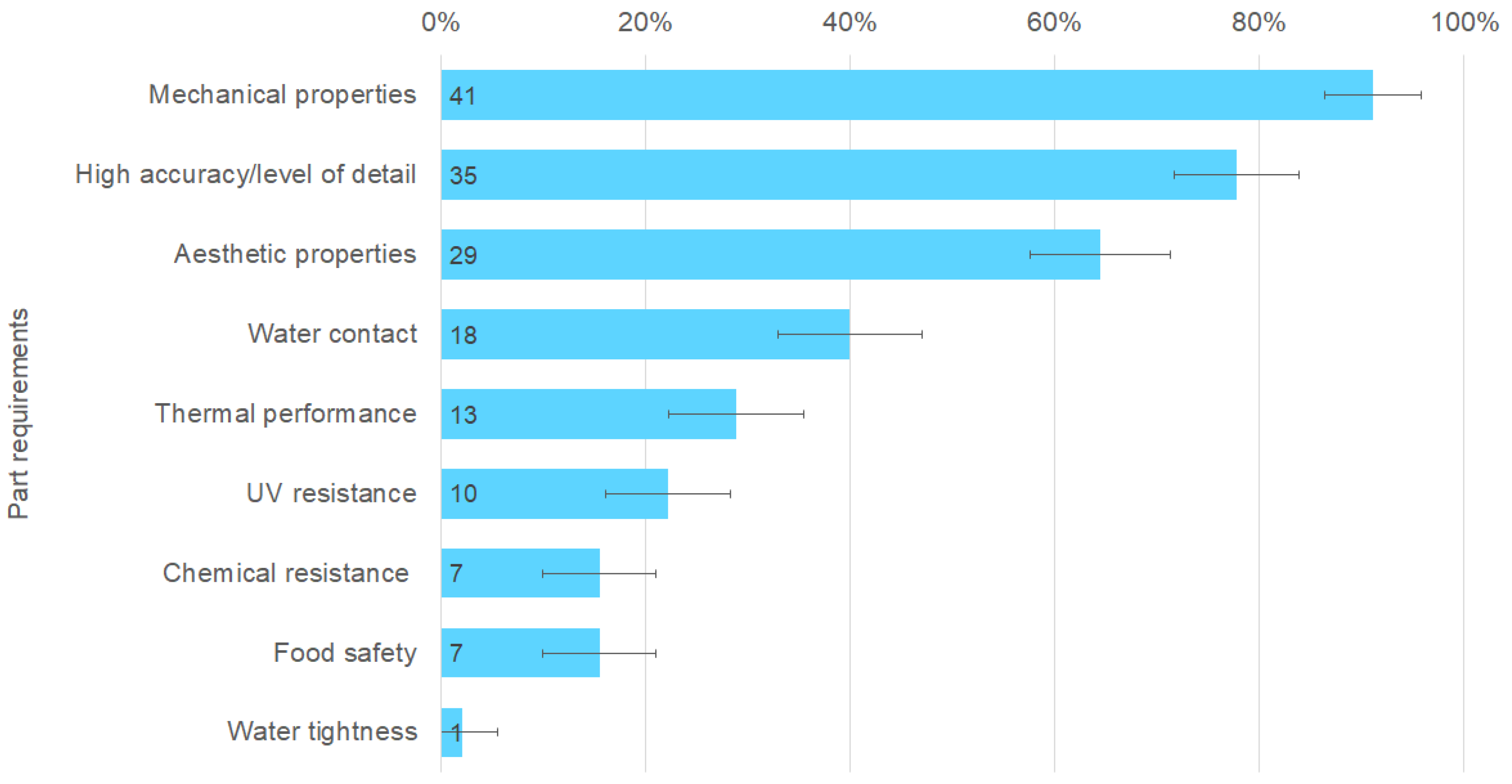
Part Requirements
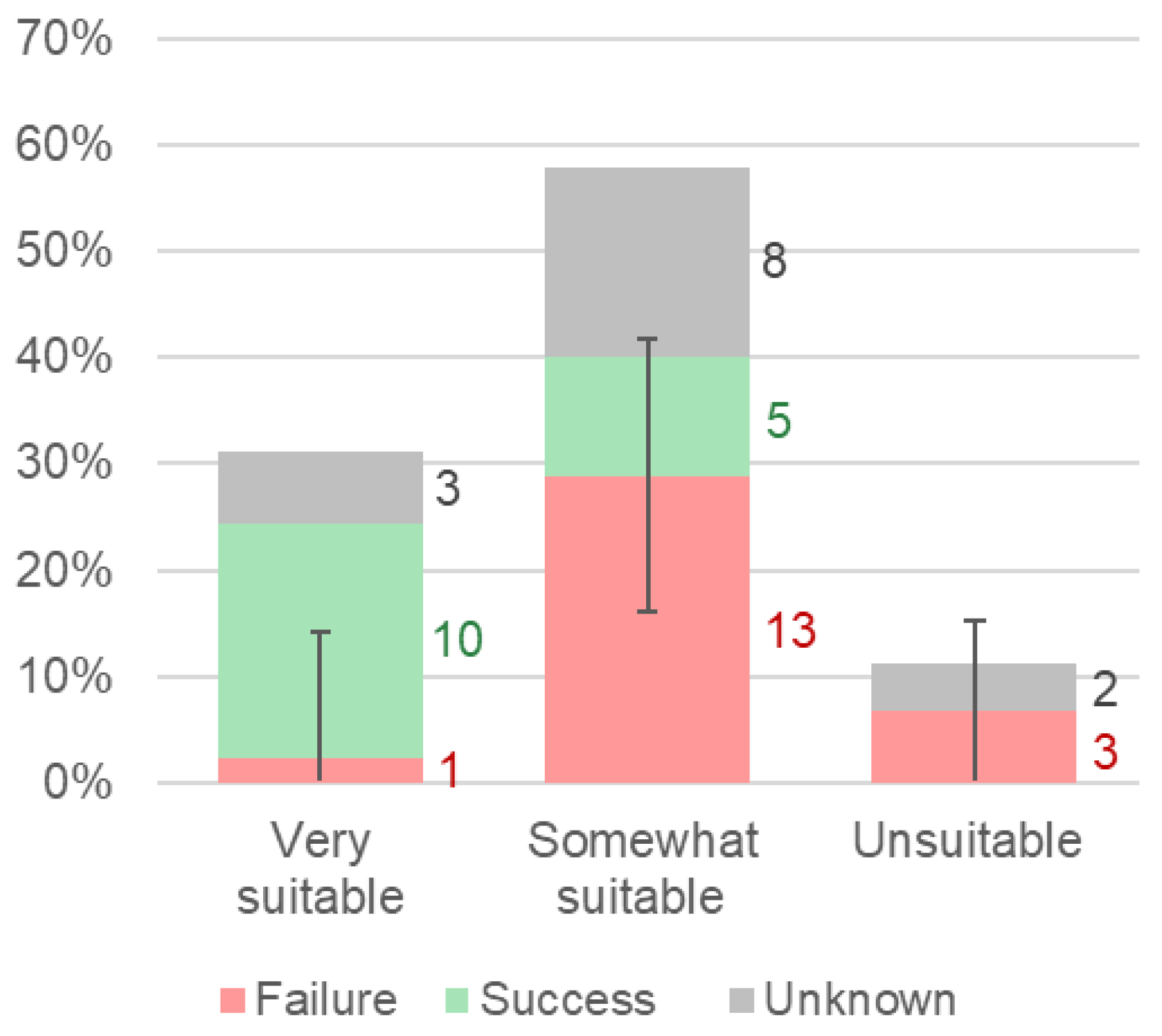
Overall Part Suitability
4. Discussion
4.1. 3DPfR Framework
4.1.1. Finalising the Framework
4.1.2. Complications in Framework Application
4.2. Factors for Successful Repair
4.2.1. Previous Experience
4.2.2. Process Implementation
4.2.3. Part Complexity
4.3. Limitations and Recommendations for Future Research
5. Conclusions
Author Contributions
Funding
Institutional Review Board Statement
Informed Consent Statement
Data Availability Statement
Conflicts of Interest
Appendix A

| Code | Options | Definition | Examples from Dataset |
|---|---|---|---|
| Overall Repair Characterisation | |||
| Repair result | Failure | The manufactured part is installed but the product function is not back, or the part does not fit properly. | A 3D-printed keyboard stand clip was too small to fit in the keyboard, so it did not work. |
| Success | The part fits and the intended part functionality is restored. | The back cover of an alarm clock was successfully replaced with a 3D-printed part. | |
| Unknown | Machine error, incomplete testing phase, or otherwise insufficient information to judge the part fit and function. | Some users could not pick up their printed parts for testing as they were abroad/in different cities; for some parts, the printer ran out of filament. | |
| Repair type | Repair | The repair focuses on restoring the original function of a broken part. | A washing machine button was replaced with a 3D-printed button with the same fit and function. |
| Added value | The repair focuses on optimising the functionality of a non-broken part, or on repurposing a broken part. | A functioning Nintendo Switch joy-con rail was redesigned to make the controller more comfortable to hold. | |
| Both | The repair focuses on restoring the function of a broken part and on optimising/adding functionality/personalising the part compared to its original function. | A broken multimeter stand was replaced, and holes were added to the design to hold the probe cables. | |
| Previous experience | |||
| Previous experience | None | The participant mentions that they had not previously used CAD modelling and 3D printing, or expressed difficulty with these skills. | “… I had no prior experience with [modelling a 3D part], it was totally unfamiliar for me what I had to do” |
| Only CAD | The participant mentions experience with CAD modelling. | “… I already had some experience with modelling … The 3D printing itself I had actually never done before” | |
| Both CAD and 3DP | The participant mentions experience with CAD modelling and 3D printing. | “… I have had the privilege to gain a lot of experience within prototyping and products design also based on FDM 3D printing …” | |
| Process implementation | |||
| Analyse process steps | |||
| Define tolerance/fit | Incorrect | The participant does not recognise how loose/tight the part should fit or does not pay attention to it. | One participant measured the part cavity and gave the part the same measurements, while the part should have a looser fit. |
| Correct | The participant recognises how loose/tight the part should fit. | “Assemble type:—Loose fit” for a ring to hold a toilet seat in place. | |
| Identify part reference points and critical elements | Incorrect | The identification of part reference points and critical elements is incomplete and/or incorrect. | A coffee pot lid did not take into account the reference to the coffee maker nozzle, and thus the coffee would not flow through. |
| Correct | The identification of part reference points and critical elements is complete and correct. | A faucet knob was designed to match the existing male part of the faucet knob. | |
| Recognise assembly complications | Incorrect | The fact that a part is difficult to assemble (either due to original design/assembly or because of 3D-printed part properties) is not recognised. | A screw thread of a cupboard leg was redesigned only because the participant could not model a screw thread, but the redesign still had the same issues (too delicate to be printed). |
| Correct | The fact that a part is difficult to assemble (either due to original design/assembly or because of 3D-printed part properties) is recognised. | It was recognised that a 3D-printed closure hook for a panini maker could not snap into place like the original injection-moulded part did. | |
| Not applicable | There were no assembly complications. | A 3D-printed zipper pull could use the same assembly method as the original zipper pull. | |
| Identify part performance requirements | Incorrect | The identified performance requirements are not logical and/or incomplete. | It was not recognised that a 3D-printed beer bottle opener would require great strength and stiffness. |
| Correct | The identified performance requirements are logical and complete. | A monitor cable holder “needs to be flexible enough to clip around the pole”. | |
| Determine (missing) part geometry | Incorrect | The geometry of the part is determined incorrectly, or incorrect assumptions are made when constructing missing geometry. | It was not noticed that the walls of a lamp bracket were slanted instead of perpendicular. |
| Correct | The geometry of the part is determined correctly, and correct assumptions are made when constructing missing geometry. | The geometry of a washing machine knob was completely reconstructed with the help of the internal geometry. | |
| Recognise unsuitable part size | Incorrect | The fact that the part is too small or too large (see part unsuitability types) is not recognised. | No example available. |
| Correct | The fact that the part is too small or too large (see part unsuitability types) is recognised. | It was recognised that the handle of a vacuum cleaner was too large to fit on the build plate. | |
| Not applicable | The part was a suitable size for (desktop FDM) 3D printing. | A cooking spoon handle was small enough to fit the build plate but larger than the printing resolution. | |
| (Re)design process steps | |||
| Design a 3D-printable part | Incorrect | The part design does not meet the design rules for FDM printing by Hubs [43]. | A cupboard leg could not be replaced because the designed screw mechanism could not be printed. |
| Correct | The part design meets the design rules for FDM printing by Hubs [43]. | A vacuum bag locking mechanism was redesigned into two parts so it could be 3D printed easier. | |
| Design a functional part | Incorrect | The part design does not meet (or is not expected to meet) the performance requirements and function described in the analysis phase. | A bike light holder was redesigned so the lamp would not slip down the steering wheel, but the redesign still slipped down the steering wheel. |
| Correct | The part design meets (or is expected to meet) the performance requirements and function described in the analysis phase. | A bike tire cover attachment has the right shape to clip both the luggage rack and the bike tire cover together. | |
| Simplify complex geometry | Incorrect | The part simplification, if applied, hindered part printing and/or part function. | The attachment mechanism of a smartwatch bracelet was simplified, but it would not connect to the original mechanism of the watch itself. |
| Correct | The part simplification, if applied, improved or did not hinder part printing and/or part function. | The battery cover of a mouse was redesigned to omit non-essential holes and curves. | |
| Not applicable | The part did not have any complex geometry that needed to be simplified, or it was feasible for 3D printing without simplification. | A T-shaped bike light post was simple enough to keep the original part design. | |
| Adapt accuracy and tolerances | Incorrect | The part accuracy and tolerances needed to be adapted to fit 3D printing accuracy and tolerances, but this was performed insufficiently or incorrectly. | “I wanted to make it slightly bigger so [it] would not be too loose. But I overestimated the diameter which now result in some after processing.” |
| Correct | The part accuracy and tolerances needed to be adapted to fit 3D printing accuracy and tolerances, and this was performed correctly. | “In order to get a snug fit, I decreased the size I actually wanted in the CAD model by 0.5 mm… it was important that it was maybe a bit smaller than larger in order [to fit]” | |
| Not applicable | The part accuracy and tolerances were feasible for 3D printing and did not have to be adapted. | The fit of a teapot lid was loose enough that the accuracy and tolerances did not have to be adapted. | |
| Adapt connectors and assembly | Incorrect | Unsuitable part connectors and assembly methods, if any, have not been adapted to make them suitable for 3D printing, or have been adapted in such a way that they negatively affect the part fit and/or function. | A complex hinge was changed into a spring, but the spring redesign would not have any flexibility, nor act as a spring. |
| Correct | Unsuitable part connectors and assembly methods, if any, have been adapted to make them suitable for 3D printing, if needed. | A bike cover holder was designed that clamped over the cover, as the hole where the original bracket had been attached was broken beyond use. | |
| Not applicable | The part connectors and assembly were feasible for 3D printing and did not have to be adapted. | A coat hook used screw connections, which are also feasible in the 3D-printed part. | |
| Apply added value to improve part function | Incorrect | The added value in the design, if applied, hindered part printing and/or part function. | One participant wrote their name on their guitar knob, and the only possible printing direction to do this resulted in infill material in the knob hole, which was difficult to remove. |
| Correct | The added value in the design, if applied, improved or did not hinder part printing and/or part function. | A teapot lid was redesigned to hold cookies. | |
| Not applicable | There was no added value applied in the redesign of the part; see repair type repair. | A washing machine button was replaced with a 3D-printed button with the same fit and function. | |
| Reduce excess material in design | Incorrect | The same fit and function could have been achieved with less material without too much redesign effort (e.g., the part design is unnecessarily bulky). | A faucet knob was roughly 1.5 times the size of the original knob, while this is not required for either fit or function. |
| Correct | The part design does not use more material than needed to achieve the required fit and function. | A teapot lid was simplified to a disk instead of a dome, which reduces the amount of used material. | |
| Reconfigure unsuitable part size | Incorrect | An unsuitable part size (too large/too small) has not been reconfigured to make it suitable for 3D printing, or it has been reconfigured in a way that negatively affects the part fit and/or function. | No example available. |
| Correct | An unsuitable part size has been reconfigured to make it suitable for 3D printing without negatively affecting the part fit and function. | The broken handle of a vacuum cleaner was repaired by a 3D-printed patch instead of replacing the whole handle. | |
| Not applicable | The part was a suitable size for (desktop FDM) 3D printing; see analysis step recognise unsuitable part size—not applicable. | A cooking spoon handle was small enough to fit the build plate but larger than the printing resolution. | |
| Scan part measurements | Incorrect | Measurement equipment is used incorrectly and/or one or more of the part measurements are incorrect. | “Measuring round parts and the small fins on the spoon is very hard with only a ruler.” |
| Correct | Measurement equipment is used correctly, and all part measurements are correct. | A roller blinds connector was carefully measured, and all measurements were noted in a sketch. | |
| Model part geometry | Incorrect | The 3D CAD model of the part has different measurements and/or scale compared to the scanned part measurements. | The lid for a blender was modelled/scaled incorrectly, and measured 2 cm instead of 20 cm. |
| Correct | The 3D CAD model has the same measurements and scale as the scanned part measurements. | A 3D-printed dough hook “fitted perfectly and feels steady”. | |
| Manufacture process steps | |||
| Choose optimal printing direction | Incorrect | The printing direction (part printing direction) hinders the part structure/does not benefit any part section or generates unnecessary support material. | A washing machine button (rectangular) was printed standing upright, which makes it weaker and adds support material, while it could have been printed lying flat without support material. |
| Correct | The printing direction benefits the part structure (as much as possible) and does not generate unnecessary support material. | A lid for a teapot was printed with the visible side up, so the rough surface left after post-processing would not be visible. | |
| Choose optimal printer settings | Incorrect | The chosen printing settings compromise component functions or unnecessarily increase printing time and material use. | A washing machine button was printed with 100% infill, while this part does not require great strength. |
| Correct | The chosen printing settings do not compromise component functions and do not unnecessarily increase printing time and material use. | The aeroplane model stand was printed with a “normal instead of fine profile” as it is a “fairly large part, so fine is not needed to save time”. | |
| Export model to STL file | Incorrect | Mistakes were made when exporting the 3D CAD model to STL, e.g., holes in the mesh or other issues described by Hubs [44]. | No example available. |
| Correct | The 3D CAD model from the CAD modelling software was correctly exported to an STL file format. | All cases correctly exported the model to STL. | |
| Post-process print | Incorrect | The post-processing was not fully completed, damaged the part, or affected the part’s function in some way. | A shaver attachment had narrow overhanging pins, which broke when the support underneath them was removed. |
| Correct | The post-processing was completed and did not damage/affect the part. | The brim of a cooking spoon handle was correctly removed. | |
| Not applicable | Post-processing of the part was not required. | The aeroplane model stand was printed without support, so no post-processing was required. | |
| Test process steps | |||
| Not tested | The testing phase was not conducted or completed. | “Could not test the part since I was not in Delft”. | |
| Validate print quality | Incorrect | Printing defects [45] that affect part fit and/or function are not noticed, and/or the printed part weight is compared to something other than the slicer estimate (comparing the weight of the printed part to the slicer estimate can help to judge printer performance. If the actual weight is a lot lower than the estimated weight, this can indicate printing problems such as under-extrusion). | A number of people compared the weight of the printed part to the original part, which does not say anything about under-extrusion and print quality. |
| Correct | Printing defects are noted, and the printed part weight is compared to the slicer estimate. | “Right side had a printing artefact where it was thicker”. | |
| Replace component | Incorrect | The part was not replaced in the product, or it was installed in the wrong place and/or in any other way that affected part fit and/or function. | A pineapple cutter slicer blade was installed at the wrong end of the cutter. |
| Correct | The part was replaced at the right location in the right order with the right connectors. | The dust bag locking mechanism was installed in the right order to hold the dust bag in place. | |
| Not applicable | The part could not be replaced in the product due to other incorrect steps (e.g., incorrect measurements). | A smartwatch bracelet half could not be reassembled due to incorrect measurements and incorrect redesign of the attachment mechanism. | |
| Test setup suitable | Incorrect | The test setup is not suitable to test the part as it is not similar enough to simulate use of the part. | Attaching a bike light to a candelabra and shaking it to simulate use of the bike light on a bike. |
| Correct | The test setup tests the right part behaviour in the original setup or a correct simulation of the original product. | A 3D-printed cooking spatula connector was submerged in boiling water to test the thermal performance. | |
| Iterate (optional, added after numerous participants voluntarily gave their redesign insights) | Incorrect | The redesign actions offered are not likely to solve the issues with the part fit and/or function. | The proposed redesign iteration for a bottle opener was to change the measurements, while it broke because the mechanical requirements were too high. |
| Correct | The offered redesign actions are likely to solve the issues with the part fit and/or function. | The redesign for a coffee pot lid did not work because it did not connect well to the coffee maker, and the proposed redesign was to take this element into account in the next iteration. | |
| Not mentioned | No redesign insights were mentioned. | - | |
| Part complexity | |||
| Part completeness | Complete | The original part was intact, or a broken part had no missing pieces, or geometry could be copied of identical parts. | A missing guitar tuning knob could be modelled by looking at the knobs that were still present. |
| Incomplete | The original part had partially missing or deformed geometry. | The mounting bracket of a lamp had pieces broken off that were missing. | |
| Not present | The original part was not available. | The back cover of the alarm clock was missing. | |
| Part requirements | |||
| Mechanical properties (force/flexibility/ abrasion) | Yes/No | The part requires mechanical performance to fit and function, such as strength, stiffness, bending, torsion, flexibility, elasticity, and abrasion. | A (metal) bread maker dough hook required large strength and stiffness to withstand the forces applied to it while kneading the dough. |
| High accuracy/level of detail | Yes/No | The part requires a high manufacturing accuracy and/or level of detail to fit and function. | An aeroplane model stand required higher accuracy to ensure the model aeroplane clicks in tightly. |
| Aesthetic (surface quality, colour) | Yes/No | The part is visible during use, and/or requires aesthetic properties to fit and function (e.g., smooth surface required). | The aesthetic of a desk lamp was the reason to repair it, so the 3D-printed part should not interfere with this aesthetic. |
| Water contact | Yes/No | The part requires the ability to withstand water contact in order to fit and function. | A bike light holder comes into contact with water if the bike stands outside when it rains. |
| Thermal performance | Yes/No | The part needs to withstand a certain temperature to fit and function. | A teapot lid comes into contact with hot steam. |
| UV resistance | Yes/No | The part is used in a place where it is exposed to sunlight (e.g., behind a window, outside, in a car). | A bike light holder comes into contact with UV light as bikes are used outside in the sun. |
| Chemical resistance | Yes/No | The part needs to withstand certain chemicals in order to fit and function. | A toilet seat part comes into contact with the chemicals used in household cleaning agents. |
| Food safety | Yes/No | The part comes into contact with food. | A teapot lid comes into contact with the tea while pouring the tea. |
| Water tightness | Yes/No | The part needs to hold water without leaking for a longer time period. | A blender lid needs to be watertight so the blender contents do not seep through the lid. |
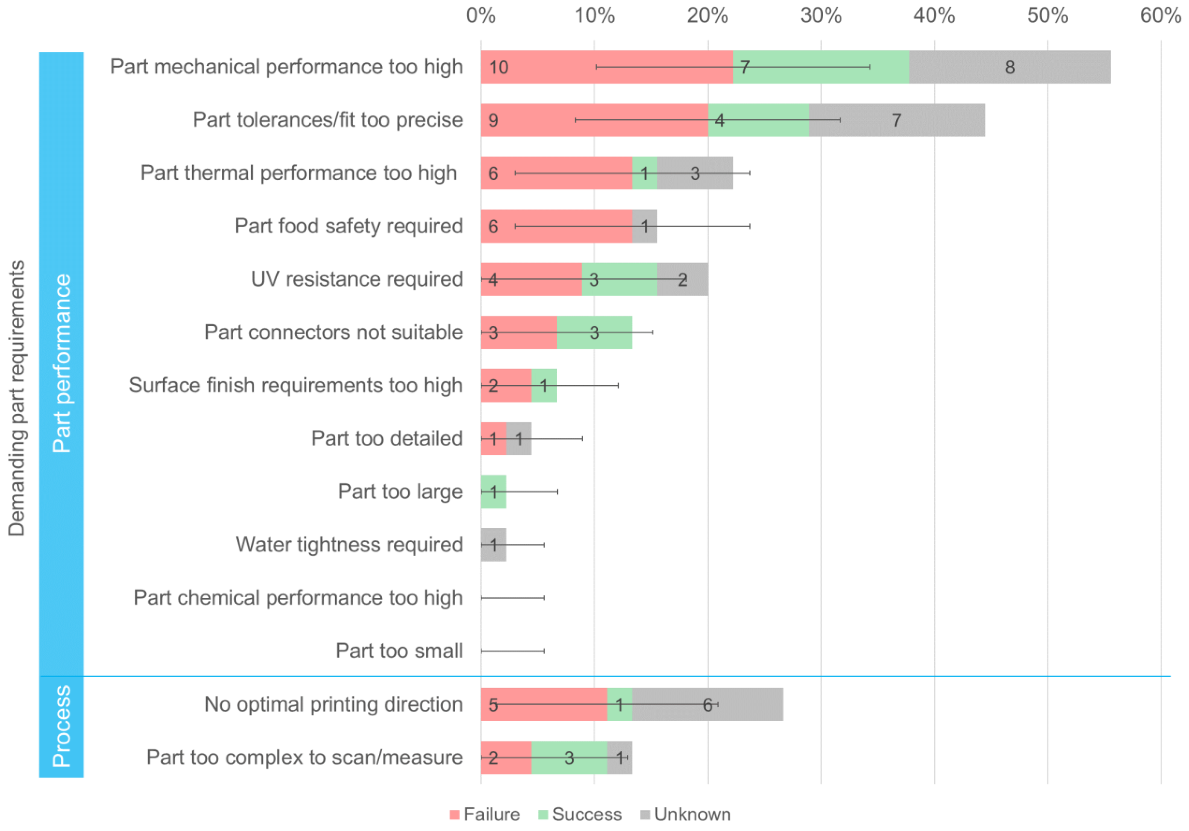
| Part unsuitability types | |||
| Part mechanical performance too high | Yes/No | The required mechanical performance (e.g., strength, stiffness, bending, torsion, flexibility, elasticity, abrasion) is too high to be feasible with (desktop FDM) 3D printing. | The forces on the dough hook of a bread maker are very likely to be too high to replicate with 3D printing. |
| Part tolerances/fit too precise | Yes/No | The required part tolerance/fit is too high to be feasible with (desktop FDM) 3D printing. | The precision required for the attachment mechanism of a smartwatch bracelet is too high to replicate with 3D printing. |
| Part thermal performance too high | Yes/No | The required part temperature is higher than the service temperature of the used material; in this case, standard PLA. | The heat of the steam in the teapot is too hot for the teapot lid, which will likely soften and maybe deform over time. |
| Part food safety required | Yes/No | The part comes into contact with food. | A cooking spatula connector that connects the handle and spoon is likely to come into contact with the contents of the cooking pot. |
| UV resistance required | Yes/No | The part is mostly used in a place where it is exposed to sunlight (e.g., behind a window, outside, in a car). | A bike light holder comes into contact with UV light as bikes are used outside in the sun. |
| Part chemical performance too high | Yes/No | The part needs to withstand chemical compounds that the used material, in this case, standard PLA, cannot withstand, e.g., antifreeze, acetone, strong acids [46]. | PLA is likely to withstand all the (common household) chemical compounds that the case study parts will encounter [46]. |
| Part connectors not suitable (Even though part connector requirements rely on other part requirements (e.g., snap fits require flexibility), it was chosen to make this a different requirement as it is (almost always) located locally and only required during assembly (not during normal use) | Yes/No | The part connectors require properties that are difficult to achieve with 3D printing, e.g., snap fits or screw thread. | The back plate of an alarm clock requires a click mechanism that needs to flex considerably, which will be challenging to achieve with 3D printing. |
| Surface finish requirements too high | Yes/No | A very smooth surface is required for the part to fit and function correctly. | The lid of a coffee pot requires a smooth surface on both sides. This is difficult to achieve, as one side needs support, which leaves a rough surface. |
| Part too detailed | Yes/No | The part requires geometry that cannot be 3D printed as it is too thin/small/etc. [43] | A shaver attachment requires very small and thin prongs, which are likely to fail during printing/post-processing. |
| Part too large | Yes/No | The part was larger than the average build plate of desktop FDM printers (200 × 200 × 200). | The handle of the vacuum cleaner was larger than the print bed. |
| Part too small | Yes/No | The part dimensions for functional elements were smaller than the average printing accuracy (± 0.3 mm). | No example available. |
| Water tightness required | Yes/No | The part needs to hold water without leaking for a longer time period. | A blender lid needs to be watertight, so the blender contents do not seep through the lid. |
| No optimal printing direction | Yes/No | There is no printing direction that does not negatively affect the part fit, part function, printing time, and/or material use. | A phone stand for a bike mount had perpendicular overhangs in all directions, and the printing direction with the least support weakens the main part’s body strength. |
Appendix B

- Test—validate print quality (29; 64%)
- (Re)design—design a 3D-printable part (19; 42%)
- (Re)design—design a functional part (16; 36%)
- (Re)design—export model to STL file (45; 100%)
- (Re)design—model part geometry (41; 91%)
References
- Cooper, T. The Circular Economy in the European Union; Springer International Publishing: Cham, Switzerland, 2020; ISBN 9783030502393. [Google Scholar]
- Šajn, N. Right to Repair; 2022. Available online: https://www.europarl.europa.eu/RegData/etudes/BRIE/2022/698869/EPRS_BRI(2022)698869_EN.pdf (accessed on 18 March 2022).
- Svensson-Hoglund, S.; Richter, J.L.; Maitre-Ekern, E.; Russell, J.D.; Pihlajarinne, T.; Dalhammar, C. Barriers, Enablers and Market Governance: A Review of the Policy Landscape for Repair of Consumer Electronics in the EU and the U.S. J. Clean. Prod. 2021, 288, 125488. [Google Scholar] [CrossRef]
- Pérès, F.; Noyes, D. Envisioning E-Logistics Developments: Making Spare Parts in Situ and on Demand. State of the Art and Guidelines for Future Developments. Comput. Ind. 2006, 57, 490–503. [Google Scholar] [CrossRef] [Green Version]
- Sasson, A.; Johnson, J.C. The 3D Printing Order: Variability, Supercenters and Supply Chain Reconfigurations. Int. J. Phys. Distrib. Logist. Manag. 2016, 46, 82–94. [Google Scholar] [CrossRef] [Green Version]
- Kim, H.; Cha, M.; Kim, B.C.; Lee, I.; Mun, D. Maintenance Framework for Repairing Partially Damaged Parts Using 3D Printing. Int. J. Precis. Eng. Manuf. 2019, 20, 1451–1464. [Google Scholar] [CrossRef]
- Holmström, J.; Gutowski, T. Additive Manufacturing in Operations and Supply Chain Management: No Sustainability Benefit or Virtuous Knock-On Opportunities? J. Ind. Ecol. 2017, 21, S21–S24. [Google Scholar] [CrossRef] [Green Version]
- Chekurov, S.; Metsä-Kortelainen, S.; Salmi, M.; Roda, I.; Jussila, A. The Perceived Value of Additively Manufactured Digital Spare Parts in Industry: An Empirical Investigation. Int. J. Prod. Econ. 2018, 205, 87–97. [Google Scholar] [CrossRef]
- Chekurov, S.; Salmi, M. Additive Manufacturing in Offsite Repair of Consumer Electronics. Phys. Procedia 2017, 89, 23–30. [Google Scholar] [CrossRef]
- Attaran, M. The Rise of 3-D Printing: The Advantages of Additive Manufacturing over Traditional Manufacturing. Bus. Horiz. 2017, 60, 677–688. [Google Scholar] [CrossRef]
- Kunovjanek, M.; Knofius, N.; Reiner, G. Additive Manufacturing and Supply Chains—A Systematic Review. Prod. Plan. Control 2020, 33, 1231–1251. [Google Scholar] [CrossRef]
- Chaudhuri, A.; Gerlich, H.A.; Jayaram, J.; Ghadge, A.; Shack, J.; Brix, B.H.; Hoffbeck, L.H.; Ulriksen, N. Selecting Spare Parts Suitable for Additive Manufacturing: A Design Science Approach. Prod. Plan. Control 2020, 32, 670–687. [Google Scholar] [CrossRef]
- Ngo, T.D.; Kashani, A.; Imbalzano, G.; Nguyen, K.T.Q.; Hui, D. Additive Manufacturing (3D Printing): A Review of Materials, Methods, Applications and Challenges. Compos. Part B Eng. 2018, 143, 172–196. [Google Scholar] [CrossRef]
- Zijm, H.; Knofius, N.; van der Heijden, M. Additive Manufacturing and Its Impact on the Supply Chain. In Operations, Logistics and Supply Chain Management; Springer: Berlin/Heidelberg, Germany, 2019; pp. 521–543. [Google Scholar]
- Yang, S.; Tang, Y.; Zhao, Y.F. A New Part Consolidation Method to Embrace the Design Freedom of Additive Manufacturing. J. Manuf. Process. 2015, 20, 444–449. [Google Scholar] [CrossRef] [Green Version]
- Sauerwein, M.; Bakker, C.; Balkenende, R. Annotated Portfolios as a Method to Analyse Interviews. DRS2018 Catal. 2018, 3, 25–28. [Google Scholar] [CrossRef] [Green Version]
- Scott, K.A.; Weaver, S.T. To Repair or Not to Repair: What Is the Motivation? J. Res. Consum. 2014, 26, 43–44. [Google Scholar]
- Sabbaghi, M.; Esmaeilian, B.; Cade, W.; Wiens, K.; Behdad, S. Business Outcomes of Product Repairability: A Survey-Based Study of Consumer Repair Experiences. Resour. Conserv. Recycl. 2016, 109, 114–122. [Google Scholar] [CrossRef] [Green Version]
- Sauerwein, M.; Doubrovski, E.; Balkenende, R.; Bakker, C. Exploring the Potential of Additive Manufacturing for Product Design in a Circular Economy. J. Clean. Prod. 2019, 226, 1138–1149. [Google Scholar] [CrossRef]
- Samenjo, K.; van Oudheusden, A.; Bolaños, J.; Flipsen, B.; Faludi, J. Opportunities For 3D-Printable Spare Parts: Estimations from Historical Data. In Proceedings of the 4th PLATE Virtual Conference, Limerick, Ireland, 26–28 May 2021. [Google Scholar]
- Kietzmann, J.; Pitt, L.; Berthon, P. Disruptions, Decisions, and Destinations: Enter the Age of 3-D Printing and Additive Manufacturing. Bus. Horiz. 2015, 58, 209–215. [Google Scholar] [CrossRef]
- Knofius, N.; Van Der Heijden, M.C.; Zijm, W.H.M. Selecting Parts for Additive Manufacturing in Service Logistics. J. Manuf. Technol. Manag. 2016, 27, 915–931. [Google Scholar] [CrossRef]
- Frandsen, C.S.; Nielsen, M.M.; Chaudhuri, A.; Jayaram, J.; Govindan, K. In Search for Classification and Selection of Spare Parts Suitable for Additive Manufacturing: A Literature Review. Int. J. Prod. Res. 2020, 58, 970–996. [Google Scholar] [CrossRef]
- Westerweel, B.; Basten, R.J.I.; van Houtum, G.J. Traditional or Additive Manufacturing? Assessing Component Design Options through Lifecycle Cost Analysis. Eur. J. Oper. Res. 2018, 270, 570–585. [Google Scholar] [CrossRef] [Green Version]
- Yang, L.; Hsu, K.; Baughman, B.; Godfrey, D.; Francisco Medina, M.M.; Wiener, S. Design for Additive Manufacturing. In Additive Manufacturing of Metals: The Technology, Materials, Design and Production; Springer International Publishing AG: Cham, Switzerland, 2017; pp. 81–160. ISBN 978-3-319-55128-9. [Google Scholar]
- Ganter, N.V.; Bode, B.; Gembarski, P.C.; Lachmayer, R. Method for Upgrading a Component within Refurbishment. Proc. Des. Soc. 2021, 1, 2057–2066. [Google Scholar] [CrossRef]
- Wiberg, A.; Persson, J.; Ölvander, J. Design for Additive Manufacturing—A Review of Available Design Methods and Software. Rapid Prototyp. J. 2019, 25, 1080–1094. [Google Scholar] [CrossRef] [Green Version]
- Leary, M. Digital Design for AM; Elsevier: Amsterdam, The Netherlands, 2020; ISBN 9780128167212. [Google Scholar]
- Haruna, A.; Jiang, P. A Design for Additive Manufacturing Framework: Product Function Integration and Structure Simplification. IFAC-PapersOnLine 2020, 53, 77–82. [Google Scholar] [CrossRef]
- Vaneker, T.; Bernard, A.; Moroni, G.; Gibson, I.; Zhang, Y. Design for Additive Manufacturing: Framework and Methodology. CIRP Ann. 2020, 69, 578–599. [Google Scholar] [CrossRef]
- Lindemann, C.; Reiher, T.; Jahnke, U.; Koch, R. Towards a Sustainable and Economic Selection of Part Candidates for Additive Manufacturing. Rapid Prototyp. J. 2015, 21, 216–227. [Google Scholar] [CrossRef]
- Park, M. Print to Repair: Opportunities and Constraints of 3D Printing Replacement Parts. In Proceedings of the PLATE: Product Lifetimes And The Environment, Nottingham, UK, 17–19 June 2015; pp. 270–276. [Google Scholar]
- Terzioğlu, N.; Brass, C.; Lockton, D. 3D Printing for Repair: A Paradigm Shift in Fixing Our Relationships with Things. In Proceedings of the Sustainable Innovation 2016: Circular Economy Innovation & DesignAt: University for the Creative Arts, Epsom, UK, 7–8 November 2016; pp. 274–281. [Google Scholar]
- Lorenzen, A.; Paape, A. Leitfaden Für Den Einsatz 3D-Gedruckter Ersatzteile in Der Reparatur; 2018. Available online: https://3d-reparieren.de/materialien-und-downloads/#broschuere (accessed on 28 September 2020).
- Beerkens, T. Application of 3D Printing in Repair. Master’s Thesis, Delft University of Technology, Delft, The Netherlands, 2017. [Google Scholar]
- Agresti, A.; Coull, B.A. Approximate Is Better than “Exact” for Interval Estimation of Binomial Proportions. Am. Stat. 1998, 52, 119–126. [Google Scholar]
- Roozenburg, N.F.M.; Eekels, J. Product Design: Fundamentals and Methods; Wiley: Hoboken, NJ, USA, 1995; ISBN 978-0471954651. [Google Scholar]
- Terzioğlu, N.; Wever, R. Integrating Repair into Product Design Education: Insights on Repair, Design and Sustainability. Sustainability 2021, 13, 10067. [Google Scholar] [CrossRef]
- Beerkens, T. Repair Using 3D Printing: 3 Reproduction. Available online: https://www.instructables.com/Repair-Using-3D-Printing-3-Reproduction/ (accessed on 6 December 2021).
- Pozo Arcos, B.; Bakker, C.; Flipsen, B.; Balkenende, R. Practices of Fault Diagnosis in Household Appliances: Insights for Design. J. Clean. Prod. 2020, 265, 121812. [Google Scholar] [CrossRef]
- Beerkens, T. Repair Using 3D Printing: 1 Decomposition. Available online: https://www.instructables.com/Repair-Using-3D-Printing-1-Decomposition/ (accessed on 3 November 2021).
- Lipton, J.; Witzleben, J.; Green, V.; Ryan, C.; Lipson, H. Demonstrations of Additive Manufacturing for the Hospitality Industry. 3D Print. Addit. Manuf. 2015, 2, 204–208. [Google Scholar] [CrossRef]
- Brockotter, R. Key Design Considerations for 3D Printing. Available online: https://www.hubs.com/knowledge-base/key-design-considerations-3d-printing/ (accessed on 1 June 2022).
- Bournias Varotsis, A. Understand and Fix Common STL File Errors. Available online: https://www.hubs.com/knowledge-base/fixing-most-common-stl-file-errors/ (accessed on 1 June 2022).
- Simplify3D Print Quality Troubleshooting Guide. Available online: https://www.simplify3d.com/support/print-quality-troubleshooting/ (accessed on 1 June 2022).
- Prusa Polymers Team Chemical Resistance of 3D Printing Materials. Available online: https://prusament.com/chemical-resistance-of-3d-printing-materials/ (accessed on 1 June 2022).


| Topic | Code | Options |
|---|---|---|
| General | Repair result | Success/Failure/Unknown |
| Repair type | Repair/Added Value/Both | |
| Previous experience | Previous experience | None/Only CAD/Both CAD and 3D printing |
| Process implementation | Analyse/Redesign/Manufacture/Test process steps e.g., Define tolerance/fit | Incorrect/Correct/Not applicable * |
| Part complexity | Part completeness | Complete/Broken/Missing |
| Part suitability | Very suitable/Somewhat suitable/Unsuitable | |
| Part requirements e.g., Flexibility | Yes/No | |
| Unsuitable part requirements e.g., Part mechanical performance too high | Yes/No |
| Product and Part | Repair Result | No. of Iterations | Total Time Spent * | Print Time Final Iteration | Redesign Approach |
|---|---|---|---|---|---|
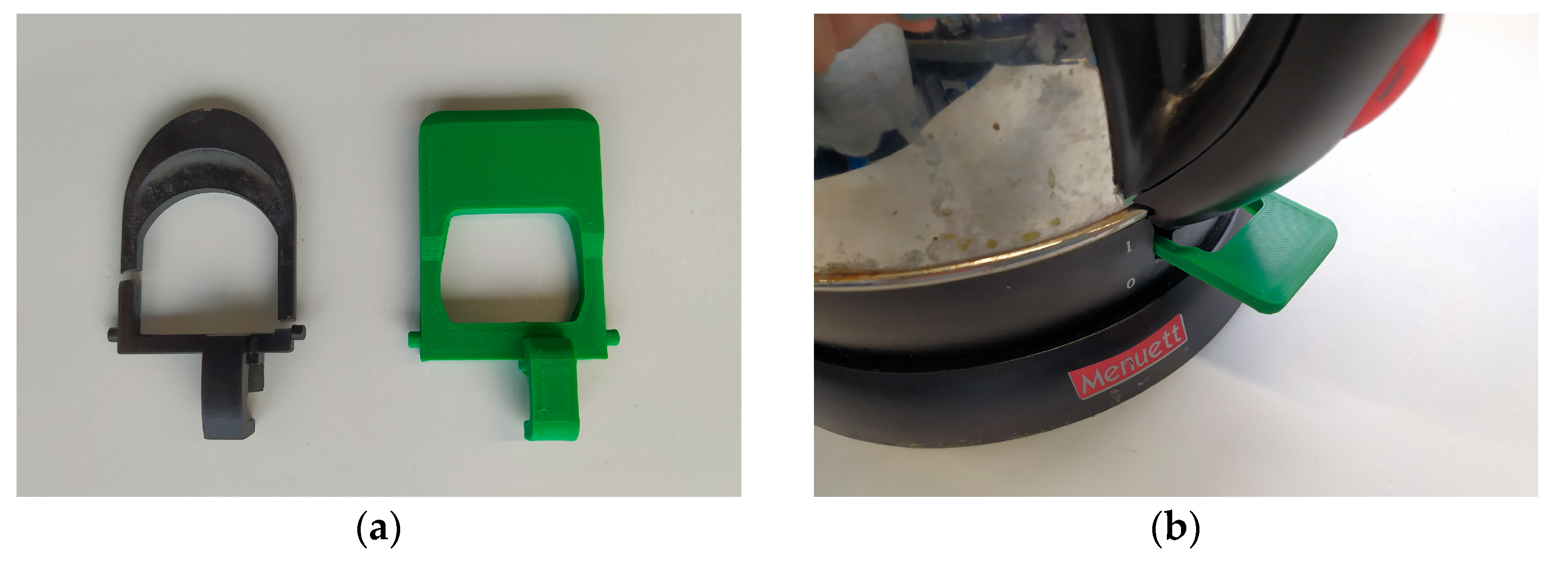
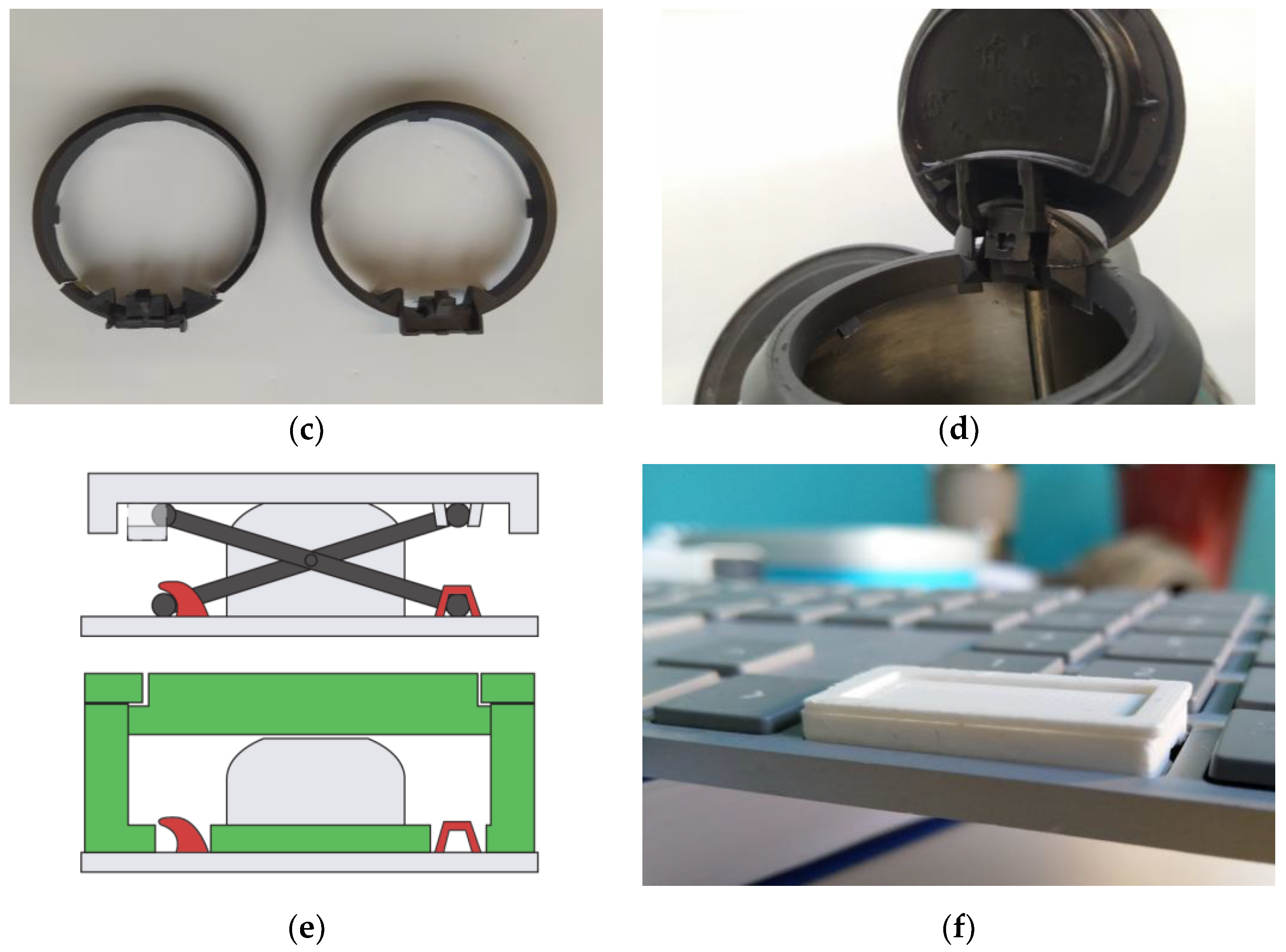
| Kettle— switch | Success | 4 | 20 h | 1 h 53 min |
|
| Kettle— locking ring | Success, with heat-resistant PLA | 5 | 21 h | 3 h 5 min |
|
| Keyboard— key attachment | Fail | 7 | 35 h | 1 h 4 min |
|
Disclaimer/Publisher’s Note: The statements, opinions and data contained in all publications are solely those of the individual author(s) and contributor(s) and not of MDPI and/or the editor(s). MDPI and/or the editor(s) disclaim responsibility for any injury to people or property resulting from any ideas, methods, instructions or products referred to in the content. |
© 2023 by the authors. Licensee MDPI, Basel, Switzerland. This article is an open access article distributed under the terms and conditions of the Creative Commons Attribution (CC BY) license (https://creativecommons.org/licenses/by/4.0/).
Share and Cite
van Oudheusden, A.; Bolaños Arriola, J.; Faludi, J.; Flipsen, B.; Balkenende, R. 3D Printing for Repair: An Approach for Enhancing Repair. Sustainability 2023, 15, 5168. https://doi.org/10.3390/su15065168
van Oudheusden A, Bolaños Arriola J, Faludi J, Flipsen B, Balkenende R. 3D Printing for Repair: An Approach for Enhancing Repair. Sustainability. 2023; 15(6):5168. https://doi.org/10.3390/su15065168
Chicago/Turabian Stylevan Oudheusden, Alma, Julieta Bolaños Arriola, Jeremy Faludi, Bas Flipsen, and Ruud Balkenende. 2023. "3D Printing for Repair: An Approach for Enhancing Repair" Sustainability 15, no. 6: 5168. https://doi.org/10.3390/su15065168