Article

Development of a Construction-Site Work Support System Using BIM-Marker-Based Augmented Reality

School of Architectural Engineering, Hongik University, Sejong 30016, Republic of Korea
*
Author to whom correspondence should be addressed.
Sustainability 2023, 15(4), 3222; https://doi.org/10.3390/su15043222
Submission received: 22 December 2022 / Revised: 1 February 2023 / Accepted: 7 February 2023 / Published: 10 February 2023
(This article belongs to the Topic 3D Computer Vision and Smart Building and City)

Abstract

:
Augmented reality (AR) in 3D has been proposed as a way to overcome the shortcomings of 2D drawings. In particular, marker-based AR is known to be more accurate in implementation, but it is not easy to use on construction sites because it requires more time and effort to create corresponding markers for information. Therefore, the purpose of this study was to develop a building information modeling (BIM)-based AR construction work support system that can be applied to construction sites by automatically generating markers. The system algorithm consists of three modules. The first module classifies and groups the objects of the BIM-based 3D model by work order. The second is used to reconstruct the 3D model by groups and automatically generate the corresponding individual markers for each object. The third specifies the marker position and implements AR by automatically matching of 3D model objects to the corresponding markers. To verify this system, a case study was implemented by projecting the BIM-marker-based AR of a 3D model on an existing building. The results show that the developed system provides 3D models and work-related information in AR at the correct scale, size, and location.

1. Introduction

1.1. Research Background and Purpose

Augmented reality (AR) can visualize information in the real world by overlaying virtual 3D graphics on reality to give the impression that the resulting images actually exist [1]. In the case of modeling using AR, because the observer receives information in the background of reality, it is easier to understand the relationship between reality and augmented virtual reality (VR) [2]. This enables inexperienced workers to be trained in a faster and less expensive manner, and it is easier for skilled workers to correct their mistakes and misinformation [3]. Similarly, by projecting the shape information and attribute information of the building information modeling (BIM)-based 3D model onto the actual object, it is possible to reduce errors related to the interpretation of drawings that may occur at the construction site [4]. Therefore, there can be a markerless method and a marker method for implementing a 3D model in AR [5]. The markerless method is a method of augmenting a virtual object using methods such as GPS. In this method, AR can be executed without a separate marker production and installation process in the field; therefore, the additional time or effort is relatively small. However, such problems as slow recognition of objects in AR or shaking of augmented objects when implemented indoors have occurred [6]. In contrast, the marker method employs the ID concept that implements AR by superimposing a 3D model on the location of a unique marker (QR code, picture, etc.) attached to a specific location (a drawing or a specific surface of a facility) [7]. Such a marker method can be used as a tool to overcome the disadvantages of the markerless method and to reduce drawing interpretation errors and construction errors by superimposing and visualizing a 3D-modeled object on a construction site. For example, in case studies for inspecting rebar assemblies using AR at a construction site, it was found that the times required for the inspection of each case were 1.8 and 2.4 times shorter than the general inspection times [8]. However, the marker method has the following limitations: (a) significant time is required to generate the information of each object of the 3D model and match the information to markers [9,10,11,12], (b) it is cumbersome because markers must be installed in advance, and maintenance is difficult because they are easily damaged by external factors (weather, dust, etc.) on a dynamic construction site [13,14,15], (c) it is very difficult to reuse the object information of the 3D model implemented with AR [2], and (d) the position and direction of the augmented 3D model objects change according to the position and direction of the marker [16].
Therefore, this study focused on developing system modules that improve the limitations of existing studies by automatically abstracting the information of 3D model objects designed with BIM, automatically generating associated markers, and then matching these two. In addition, the main purpose of this study was to develop a BIM-marker-based AR work support system that can solve such problems as work errors that can occur when working with 2D drawings at a construction site using the developed system modules.

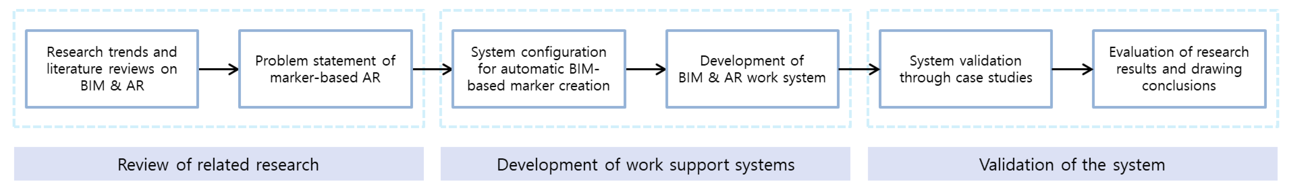
1.2. Research Method and Scope

Figure 1 shows the research method and scope for developing a work support system that can apply BIM-marker-based AR to construction sites. This research process proceeded in the following order: reviewing existing research trends and the literature, developing the system, verifying the system, and presenting results. First, the need to increase the usability of the BIM-marker-based AR in construction sites was identified, and four major problems were derived through the analysis of related studies. Next, a BIM-marker-based work support system consisting of three modules was designed to solve these problems. The Autodesk Revit, Dynamo, 3ds Max, and Unity programs were used for the algorithm configuration and program development to operate the three modules. To correct algorithm errors for automation and accuracy improvement in the system development process, a part of the building was modeled as a BIM-based 3D model and used as a test bed. The level of detail (LOD) of 3D modeling was LOD300, which makes accurate analysis possible by specifying the material information and specifications of various members based on building drawings. Finally, the newly created BIM-based 3D model using the system was implemented as marker-based AR. The usability of the system developed was verified by comparing the positions of each projected 3D model object with the actual structure. In the verification process, a solution to the problems presented above was obtained, along with a comparative analysis with the existing technology implementation process.

2. Research Trends and Literature Review

2.1. Enhancement of Applicability of 3D Digital Model to Construction Site

Owing to the enlargement, complexity, sophistication, and irregularity of construction projects, methods of sharing information using 2D drawings have limitations. Accordingly, the use of BIM-based 3D modeling or VR to deliver visual information more effectively is under consideration. Han, M.Y. et al. stated that it is possible to improve collaboration and efficiency among construction project participants through visual understanding when BIM using a 3D model is introduced [17]. In their study, such benefits as significant time savings, fewer errors and omissions, and improved construction productivity were identified. Similarly, Lee, M.J. et al. found that 3D models based on BIM can suppress errors in the construction phase that may occur because of differences in the interpretation of 2D paper drawings [18]. Figure 2 shows AR application case presented in their article. Methods for utilizing digital 3D drawings or AR/VR have been reviewed and studied. In this regard, Schiavi B. et al. pointed out that the BIM data processing method is different for each project, and the hard-coding method makes it difficult for users to combine BIM with AR, because the user should have constants or variables directly in the source code for each project [19]. Lee K.H. et al. examined the problem of the occurrence of errors in the positions of augmented objects [20]. Therefore, Pham, H. et al. argued that it is not easy to find examples of using AR on actual construction sites [21]. For this reason, AR is effective in several construction applications, but most research has been conducted in confined environments [22,23,24,25,26]. Therefore, in this study, we attempted to develop a construction-site work support system for the visualization of BIM-based 3D models using marker-based AR to help solve the above-mentioned problems.

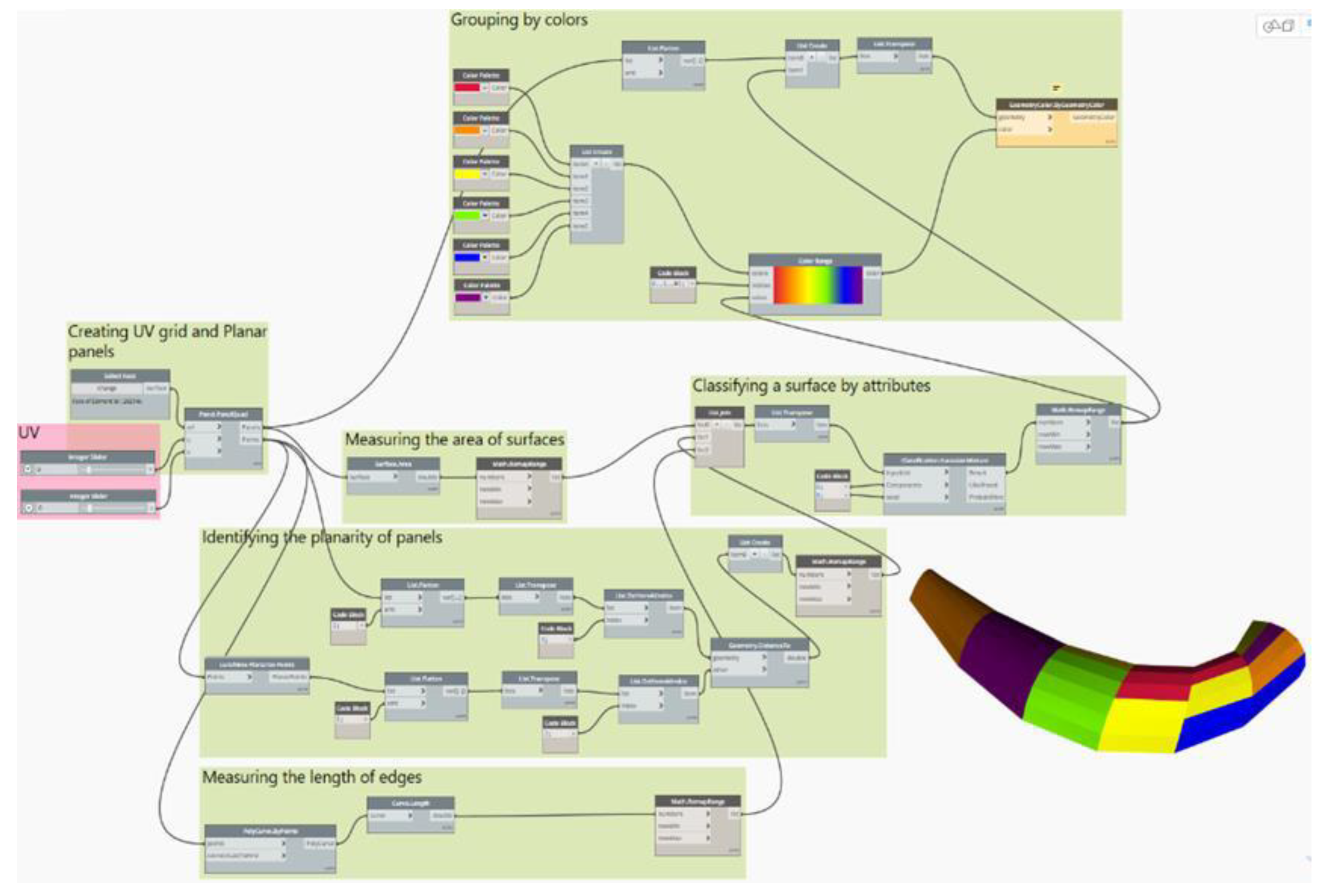
2.2. Case Studies of BIM Application Using Revit Dynamo

Autodesk’s Revit software suggests that the digital 3D model and various useful pieces of information contained in the model can be utilized throughout the building life cycle through the parameters configured for each object. Here, the parameters include property information such as the position, size, and material of the object, and new types of parameters can be added and utilized as needed. Dynamo, one of Revit’s plugins, can be easily utilized to create new parameters using built-in nodes and Python scripts, and can also modify the object information of 3D models created based on BIM. Using this, Shin J.S. et al. created a design bases information layer when modeling the Advanced Power Reactor 1400MWe (APR1400-class) next-generation nuclear power plant based on BIM [27]. Park S.H. et al. added schedule information to a BIM-based 3D model using Excel and Dynamo [28]. As shown in Figure 3, Lee et al. proposed a framework for optimizing and dividing the freeform surface of a 3D model created by parametric design using Dynamo [29]. Using this framework, free-form surfaces were divided into 36 surfaces based on geometric properties (size, flatness, and length) and divided into six colors depending on whether each surface fits the flat panel. Yoon J.W. et al. also developed a Dynamo algorithm that classifies 3D models according to work schedules and helps create initial schedules using room functions and parameters [30]. Therefore, the purpose of this study was to develop an algorithm for automatic marker creation and 3D model reconstruction of BIM using Dynamo, which enables various functions to be performed using BIM data.

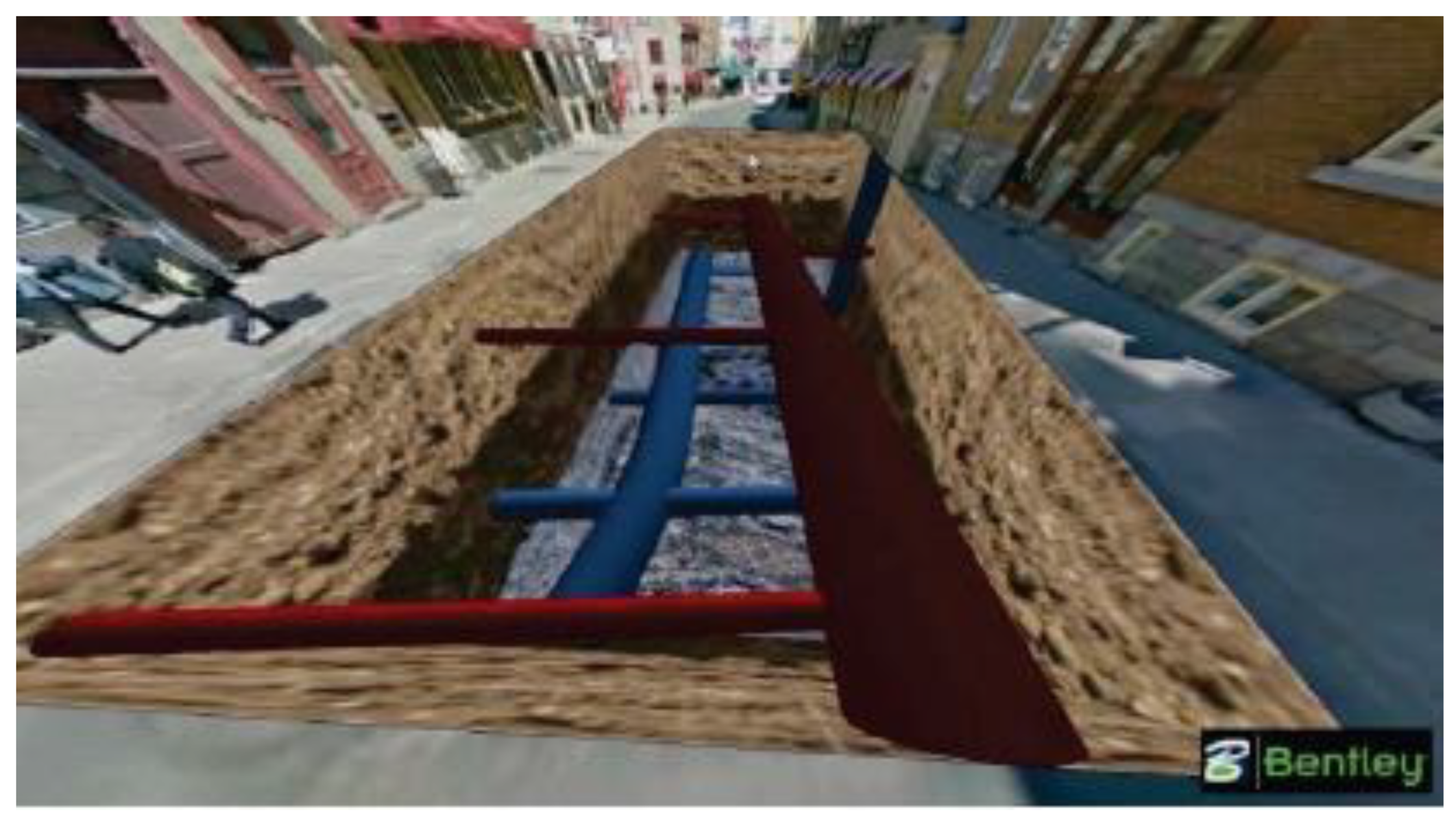
2.3. Marker-Based AR Studies

As Lee Y.J. et al. found, markers in marker-based AR are used as anchors to specify the exact location of the 3D model in the AR visualization phase [31]. Jad C. et al. found that the position of the 3D model was augmented by placing the marker image at coordinates (0,0,0) in marker-based AR, and the size and direction of the augmented 3D model were also changed according to the size and direction of the marker. [32]. Taking advantage of such marker-based AR, Kim S.Y. et al. developed and tested a marker-based rebar measurement application, as shown in Figure 4 [8]. Kieran W.M. et al. showed that the marker-based augmented BIM-based 3D model is more accurate than markerless AR. However, it was also discovered that it is difficult to use the marker at an actual construction site because each object of the augmented 3D model must be augmented at a precisely specified position from the matching position of each marker, and the corresponding markers should be installed at the exact construction site location [33]. Therefore, as Moon S.Y. et al. indicated, the limitations of marker-based AR are that more time and effort are required for marker production because there are more objects [6]. Furthermore, as Kwon, O.S. et al. concluded, significant effort must be devoted to the reconstruction of the 3D model corresponding to each marker [34]. Therefore, this study attempted to solve the indicated limitations and increase the accuracy and usability of BIM-marker-based AR.

2.4. BIM-Based AR Implementation by Unity

Unity is a game engine that supports the development of AR and VR content. Kun Chi W. et al. created an application that provides BIM and AR system information by utilizing Unity and the C# programming language, and they proved that the icon BIM model is augmented with the marker when the marker icon and BIM model share the coordinates (0,0,0) of the application [35]. Liu Y. et al. presented a method for extracting a 3D model generated by Revit into Unity [36], and James G. et al. developed a multi-user collaboration system that supports design and construction using this method [37]. Figure 5 shows the BIM-based member information visualization system developed by Jeon, H.I. et al. [38]. In this study, Unity was used to develop an automatic matching module between the created marker and 3D model, and the developed system was verified through the implementation of BIM-marker-based AR in the case study.

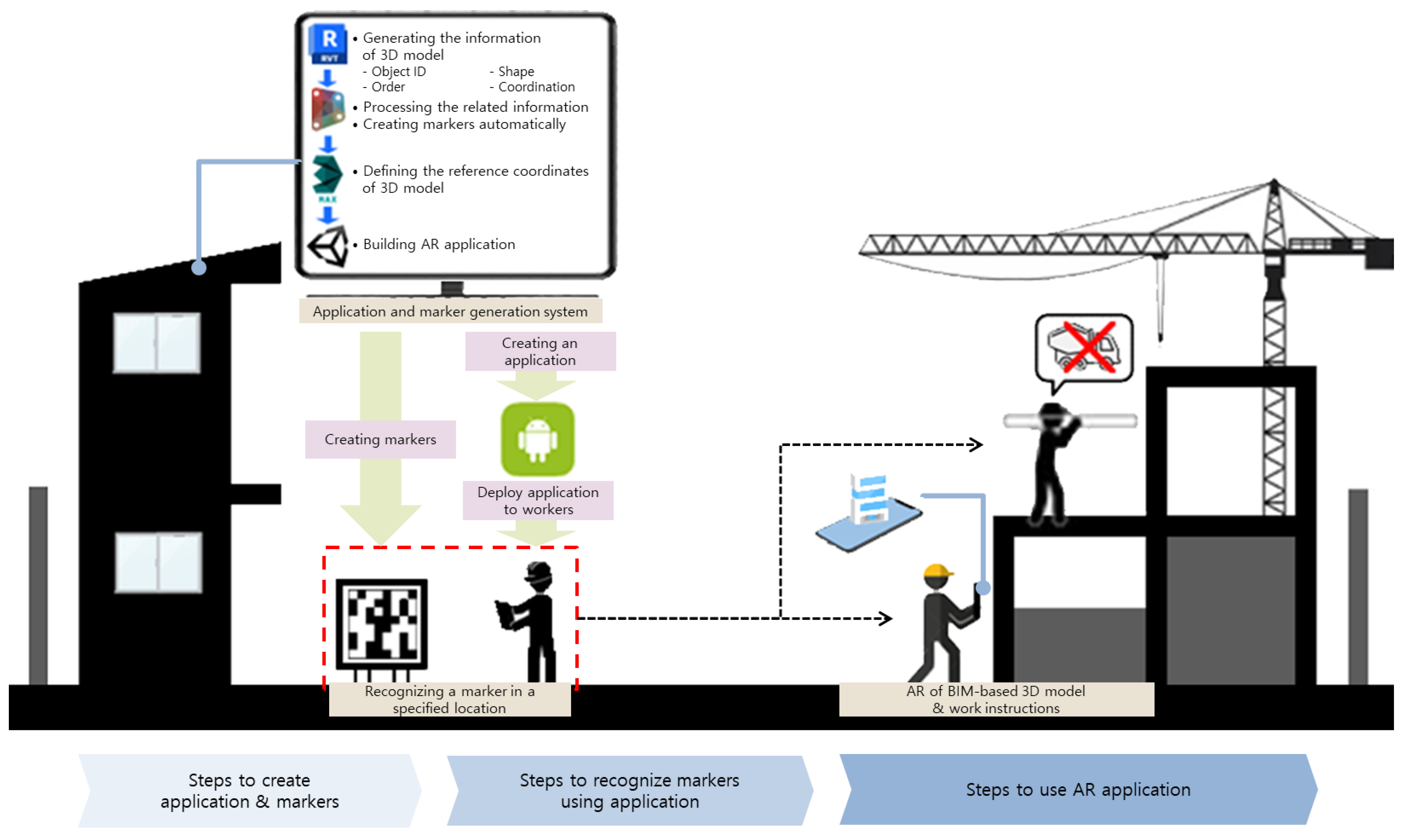
3. BIM-Marker-Based AR CWSS

3.1. CWSS Overview

The construction work support system (CWSS) is a system that enables workers to view information on the work to be performed during a day at the construction site and the 3D model corresponding to the work at the designated work location using BIM-marker-based AR. Figure 6 shows a conceptual diagram of the composition and utilization of the CWSS. Each of the four main software packages included in this system performs the following functions.
First, a 3D model constructed using Autodesk Revit software version 2019.2 is ordered by the construction work manager according to the construction performance plan by zone and object. Here, “zone” means using Revit’s Room function to divide the 3D model into spatial units, and objects contained in one zone must be independent in terms of work relationships with objects contained in another zone.
Second, Dynamo version 1.3.4 is utilized as software for processing object-related data and automatically generating corresponding markers according to the order of works assigned by zone and object. A number of nodes are clustered using the user node functionality to facilitate the use of Dynamo by nonexperts.
Third, 3ds Max version 2020.3.6 is used to designate the reference coordinates of the reconstructed BIM-based 3D model. When AR is used at a construction site, the coordinates of each object in the 3D model are arranged with the actual position of the marker as the reference coordinates (0,0,0).
Fourth, Unity version 2020.3.12 is used to implement the AR application with the 3D model with coordinate values, corresponding markers, and related work information. The application is built on an Android-based device to make a flexible response possible with the development of a new AR device.
To this end, AR Foundation Version 4.1.10 and the ARCore XR Plugin 4.1.10. are used. The generated application is provided to the workers, and each worker can recognize the marker installed at a specific location before performing the work and then check the 3D model and the instructions for the work to be performed at the worker’s work location with AR. In this study, a Samsung Galaxy S9, an Android-based smart device, was used to generate AR applications and recognize markers. Table 1 lists the versions and functions of each the software and hardware used in the system development in this study.

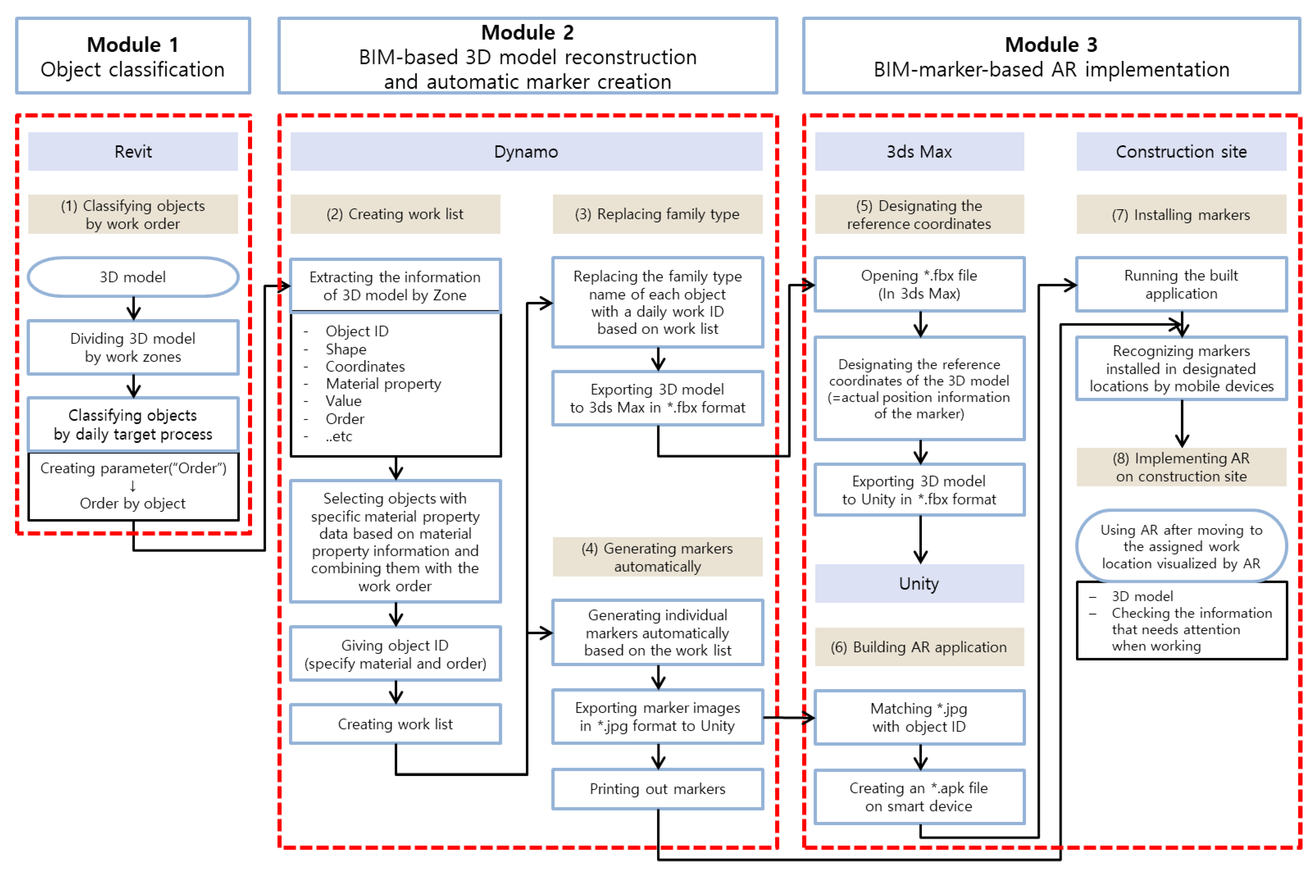
3.2. Work Support System Algorithm

As shown in Figure 7, the CWSS in this study was developed based on an algorithm composed of three modules. They consist of classification of BIM-based 3D model objects, 3D model reconstruction and automatic marker generation, and AR field application through application production.
The sub-modules constituting each module include the following processes.
(1) The 3D model created based on BIM is first divided into zones, and then the parameter “order” is added to Revit to determine the order of work for each object. In this process, the data input to the 3D model are loaded into Dynamo for each zone, and the attribute information for each object is extracted. The extracted information includes attribute information such as an object ID, a shape, a location (coordinate), and material.
(2) Objects are distinguished again by assigning a daily work ID that combines the object ID and work code based on the material data of the object, and a work list is generated based on it.
(3) In the 3D model, by replacing the “Family Type” name of each object with a daily work ID, a 3D model with a daily work ID classified for each object is created in *.fbx format.
(4) In addition, based on this work list, individual markers corresponding to each object are automatically generated in *.jpg format and entered into Unity. The generated marker is printed to implement AR at the construction site.
(5) The 3D model in the *.fbx format is extracted in the *.fbx format from Unity after the reference coordinates of the model are designated in the 3ds Max program.
(6) Markers with the 3D model extracted in *.fbx and *.jpg formats are matched in Unity based on the daily work ID and are built on smart devices in the form of applications created in *.apk format.
(7) When a marker is recognized at the marker installation location specified through 3ds Max by running the built application, a 3D object with the same ID as the marker is implemented as AR at the designated construction site location. However, because of the characteristics of marker-based AR, the marker should be installed so that it can be read in a specific direction and position.
(8) Construction workers can visually check the 3D model and text-based work contents to be done after moving to a designated workplace through an AR application. Details of the three modules constituting the system are described in more detail in the next section.

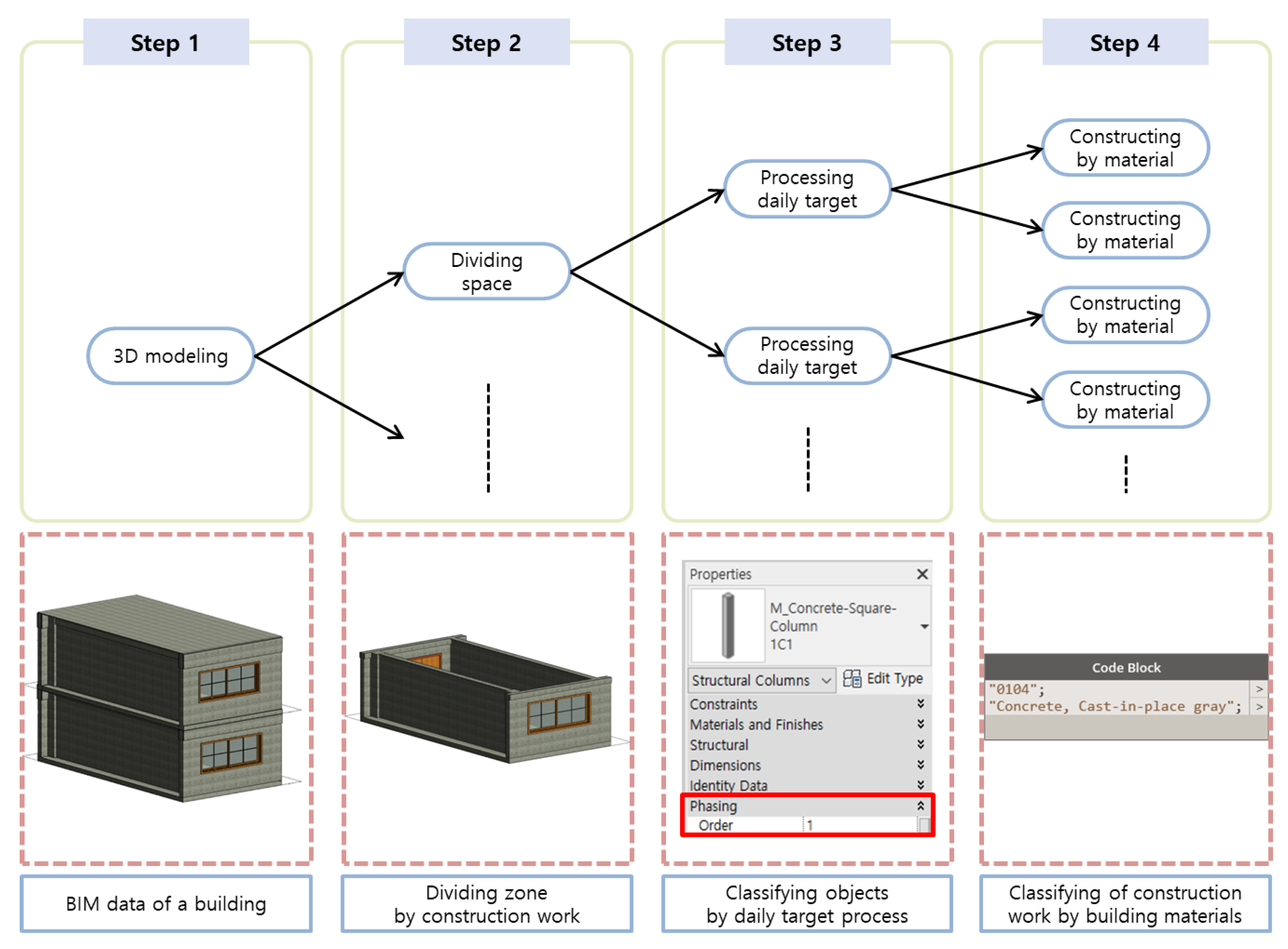
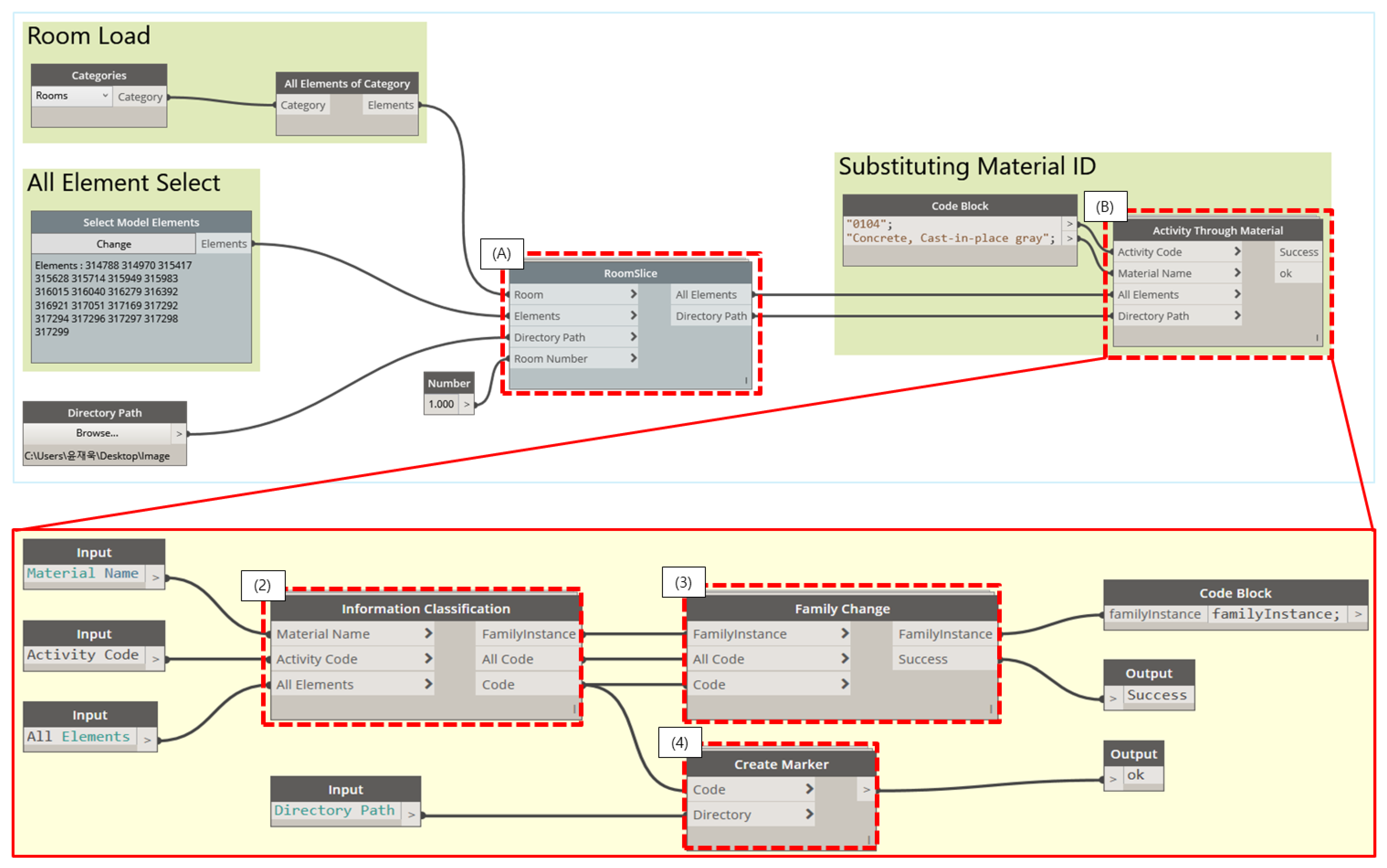
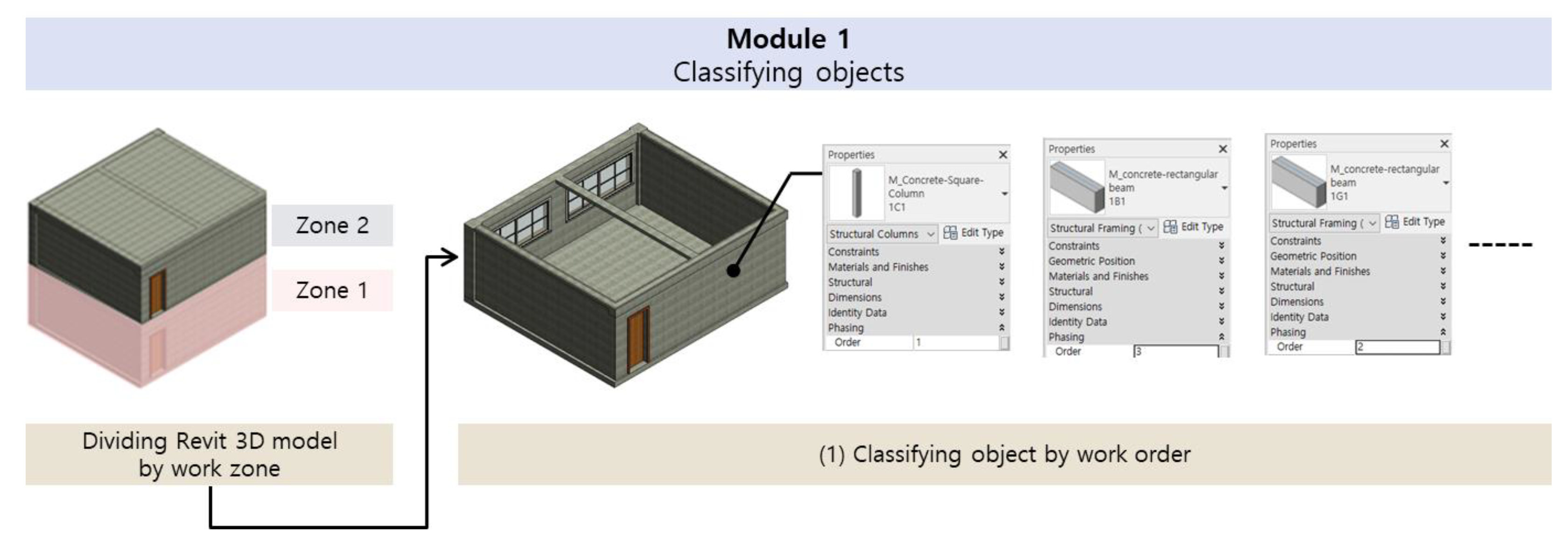
3.2.1. Object Classification by Construction Work Order

To visualize the work to be performed by workers at the construction site with BIM-based AR, the 3D model must be classified by object according to the order of work. Among the attribute information of the object constituting the 3D model of BIM, an object containing a specific parameter value may be called and modified through Dynamo. In this system, the 3D model was selectively visualized according to the work order by giving the work schedule and the related information of the object in advance using zone, the ‘order’ parameter, and “code block”. The order of construction work to be performed was first determined by dividing the BIM-based 3D model by zone, and the order of work to be performed on the day was secondarily classified through the ‘order’ parameter. After this information was loaded into Dynamo, “Work Code” and the material name of each object were entered using Dynamo’s code block node to classify attribute information for each object by work. The reason for calling an object with a material name is to distinguish the name when creating a 3D object in AR with markers by considering that the construction work is generally performed according to each construction material contained in the object. Figure 8 shows a method for classifying objects constituting BIM data by the work order.

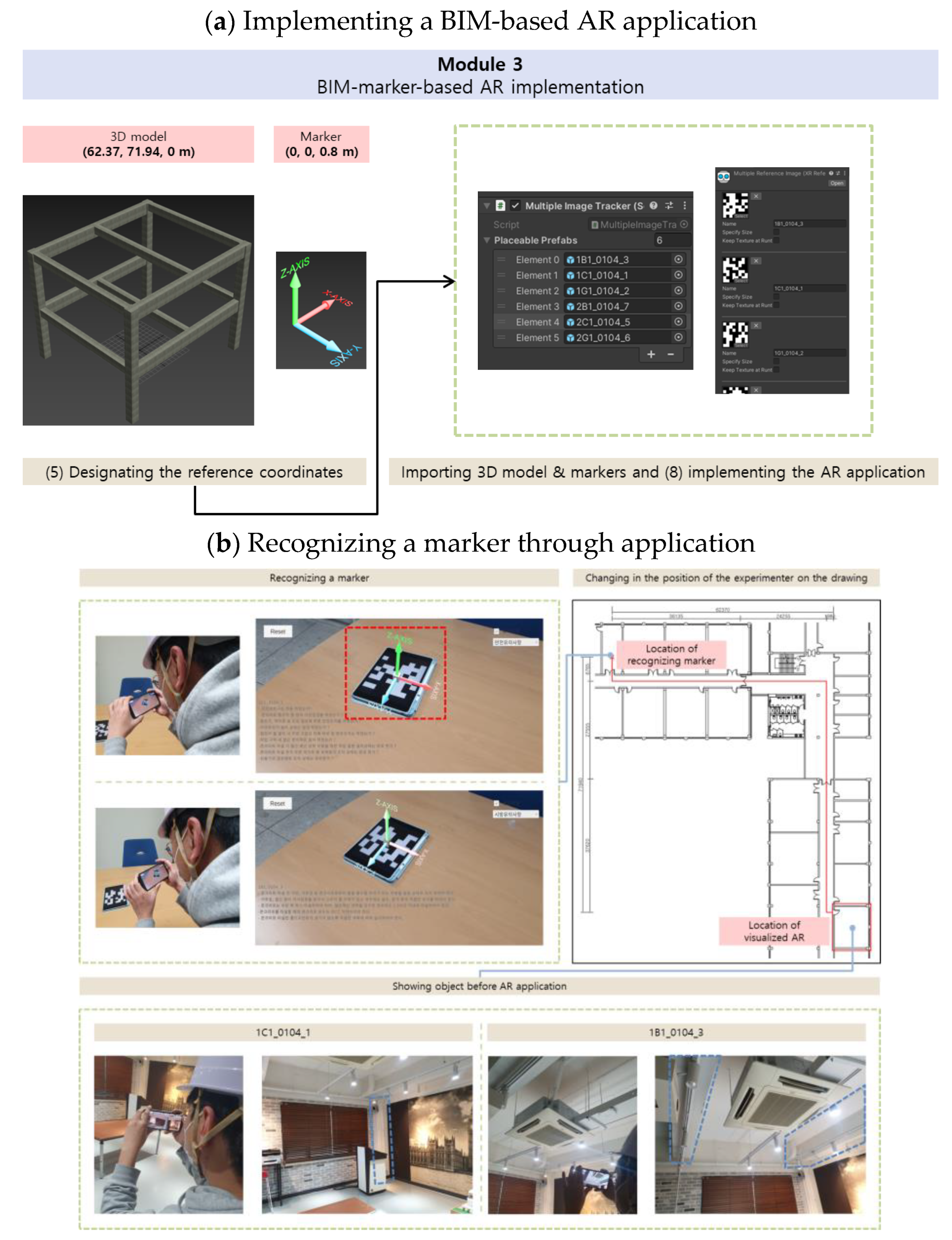
3.2.2. BIM-Based 3D Model Reconstruction and Automatic Marker Generation

The marker automatic generation module generates *.fbx files and individual markers with respective work IDs for each object of the 3D model classified according to the work order. Figure 9 shows a module for the reconstruction of 3D models and automatic generation of markers developed based on Dynamo. In particular, five ‘user nodes’ clustered according to their functions perform the process of generating work lists, reconstructing 3D models, and automatically generating markers. Each node performs the following functions.
(A) The “Room Slice” node extracts internal objects from the zone and processes them in the form of a list consisting of parameter value included in the objects. Next, the “Substationing material ID” group consists of a “Code Block” node that enters information related to work and (B) an ”Activity Through Material” node. The list of objects organized through the room slice node and the work-related information entered through the code block are entered into (B) an Activity Through Material node to change the ID of the 3D object and generate a marker. The Activity Through Material consists of a total of three user nodes.
The (2) ”Information Classification” node extracts “Order” data, distinguishing the construction order of each object among the parameters of the internal objects by zone, and combines them with a work code based on the material ID to create a daily work ID group named “Object ID_Work Code_’Order’ data value”. Objects and daily work IDs placed in the group are entered in the “Family Change” node and “Create Marker” node in the form of a list. The (3) Family Change node is a user node that automatically changes the object ID placed in the previously created group to the daily work ID. In this process, the other parameters (shape, coordinates, etc.) of the object remain constant. The BIM-based 3D model is reconstructed by replacing only the object ID, and an *.fbx file including information for each object formed. The (4) “Create Marker” node is a user node that automatically generates a marker of the same name with the entered daily work ID and outputs it in the form of a *.jpg file.

3.2.3. Creating an Application for AR Execution

To solve the issue of installing markers, which is one of the problems of the existing BIM-marker-based AR, the CWSS proposed uses 3ds Max. To recognize markers by utilizing 3ds Max, a specific fixed position is designated as the reference coordinates of the 3D model and the 3D model is augmented based on the corresponding coordinates. The 3D model with reference coordinates specified by 3ds Max in the *.fbx format is loaded back into Unity. The method proposed by Liu. Y. et al. is utilized to transfer files consisting of a daily work ID group in *.fbx format to Unity [36]. Markers with the same name as each daily work ID are also loaded into Unity. Each object in the 3D model and its corresponding marker are automatically matched on the software based on the daily work ID and are built in the form of an application on a smart device.

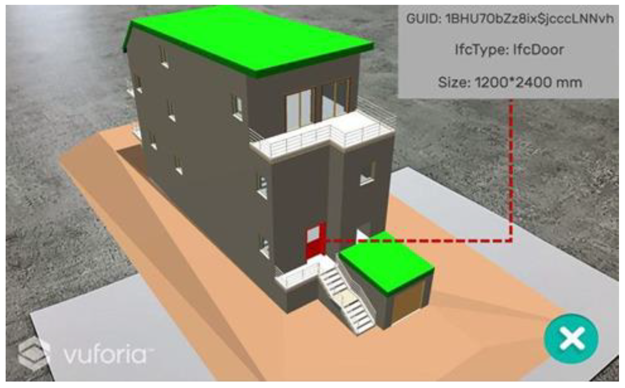
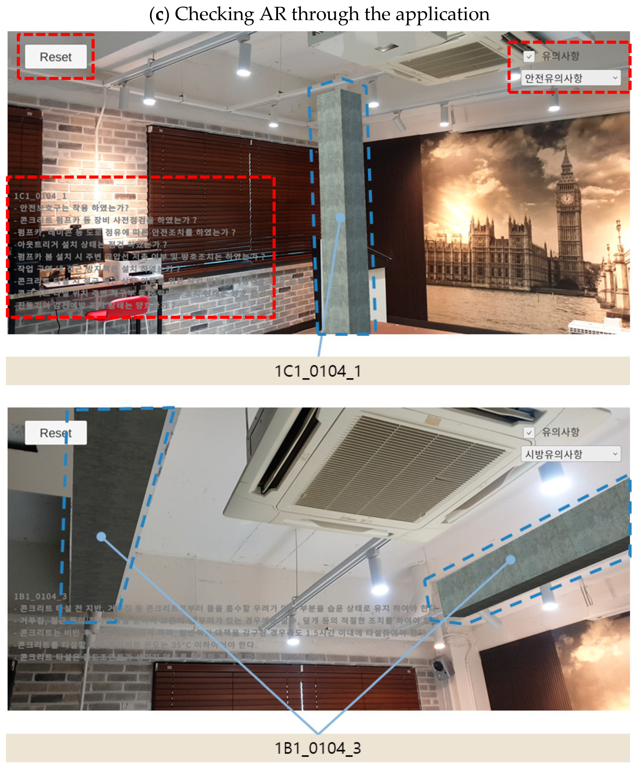
4. BIM-Marker-Based Work Support System Verification

The system developed was tested for operability by substituting it into the existing BIM-marker-based AR application process. The verification of this system mainly focused on verifying whether 3D model objects and work information can be visualized in AR at the correct location based on the markers. To this end, an experiment was conducted to compare the positions of the real objects of the previously constructed building and those of the objects of the BIM-based 3D model in AR. The experiment consisted of comparing the members constituting the classroom of a building and the 3D model objects created based on BIM by implementing them into marker-type AR using the work support system developed. The results derived by sequentially executing the three modules constituting the system are as follows. The results of Module 1 are as shown in Figure 10, and the results of classifying the BIM-based 3D model according to the object classification method presented in Figure 8 are shown. Through this module, the 3D model was divided into Zones 1 and 2, and all objects constituting each zone were extracted. In addition, after the parameter Order was added, the work order was assigned for each object.
As explained in Figure 9, Module 2 used Dynamo, and the result of executing this module is shown in Table 2. (A) The objects extracted through Module 1 were loaded into Dynamo through Room Slice, and (B) the following results were derived through user nodes constituting Activity Through Material. (2) First, through the Information Classification node, parameter data values such as object IDs, material names, and the Order of the objects constituting Zones 1 and 2 were extracted, and a daily work ID group with the name of “Object ID_Work Code_’Order’ data value” was created. (3) Next, the BIM-based 3D model was reconstructed after automatically changing the IDs of objects placed in each group to daily work IDs while maintaining other parameters of objects through the Family Change node. Through this, an *.fbx file containing all the information for each object was formed. (4) In addition, markers for each group were automatically generated through the Create Marker node.
Module 3 is configured as described in Section 3.2.3, and the results of executing this module are as shown in Figure 11. (5) The 3D model in the *.fbx format was loaded into 3ds Max to specify the reference coordinates of the model. The origin coordinates, which are the basis for the 3D model in Revit, were calibrated and designated as having x1, y1, and z1 values of 62.37, 71.94, and 0 m, respectively, based on their distance from the marker, and the coordinates of the marker were designated as having x2, y2, and z2 values of 0, 0, and 0.8 m, respectively.
As shown in Figure 11b, when a marker is installed and recognized at a designated location through an application, the three interfaces are visualized along with a 3D model corresponding to the marker. When a marker is recognized, an interface in the form of a 3D coordinate system is added to the center to indicate the installation direction of the marker. The objects in the 3D model are viewed as AR at the location of the relative coordinates designated for this interface. Therefore, when a construction worker moves to the designated coordinate position of the object through 3ds Max, the object can be seen by AR through the application of a smart device.
Figure 11c shows the screen displayed in the application after the experimenter moves. The objects are augmented 1C1_0104_1 and 1B1_10104_3, and they are augmented in a location equivalent to the existing structure. To construct a building without mistakes, not only visualized information but also information that cannot be visualized is necessary. Therefore, two interfaces are added to this module to solve these problems and improve construction worker convenience. Each interface has the following functions. The user interface, which performs the “check the notice” function displayed on the upper right side of the smart device, consists of buttons that can select the type of information that cannot be visualized entered in advance and turn on/off the visualized information as necessary. The daily work ID corresponding to the marker, technical requirements, and safety precautions for building construction of building are added to the application, and each content is displayed in the lower left corner. In addition, the work support system divides one BIM-based 3D model into multiple object groups according to the work, and automatically generates markers that match the group. Therefore, because of the nature of marker-based AR, the object being augmented varies depending on the marker, and the possibility of incorrect recognition of the marker generated in a random form may arise. To address this problem, an interface capable of removing all augmented objects without restarting the generated application is added.

5. Discussion

The algorithm constituting the construction support system using BIM-marker-based AR developed in this study provides a methodology to solve the problems in the existing system through three modules. In the first module, the room function on the 3D model created in Revit is used, and an Order parameter is added to zone the 3D model according to the construction schedule. The second module uses Dynamo to reconstruct a 3D model based on grouped objects and to creates corresponding markers automatically. The third module was developed to position markers on a construction site using 3ds Max and to align each object to that marker automatically using Unity. Through the process of specifying coordinates, markers can be recognized in an environment in which external factors that hinder marker recognition are controlled. Furthermore, the system provides a methodology to respond flexibly without coding when using BIM-marker-based AR at construction sites. In addition, the location and direction of the marker, which is composed of a simple pattern, are provided accurately through the 3D coordinate system that appears when a marker is recognized in the user interface of the application.
The system developed has automated several processes to reduce the time and effort required to implement BIM-marker-based AR. Nevertheless, there are several limitations to utilizing the system at construction sites. First, to utilize this system, a number of construction tasks should be entered into Dynamo in the form of nodes in the system. Therefore, it is necessary to reduce the work of field engineers in connection with the existing work scheduling programs. Second, because the process of creating individual markers is composed of Dynamo scripts, there is a difference in data processing time depending on computer specifications. Therefore, it may be possible to reduce the data processing time by continuously simplifying the Dynamo script. Third, the system is configured to utilize Autodesk’s Revit, Dynamo, 3ds Max, and Unity rather than a single software package. As a result, there is a possibility that some information may be missed in the processing of compatibility data for each software. The system developed in this study can observe the results of each module in the process of transmitting information between each software. However, if the data flow between different software is automated in future system development, it might be necessary to check each result in the process of inputting the output of each module into the next module. In addition, users such as field engineers should have some basic knowledge about the software such as Unity or 3ds Max to increase their utilization of the system. On the other hand, users such as construction workers need to understand how to use the application created through CWSS. If these users recognize a marker installed at a specific location once by using the application, the corresponding 3D object always will appear as an AR at the location where they should work.

6. Conclusions

AR is a technique that can make information in the real world more visible by adding virtual 3D graphics to real world images. Research has continued to be used as a communication tool between project participants through a combination of AR and BIM-based 3D models including construction project information. However, due to the various limitations caused by the characteristics of the construction site, paper drawings are still widely used as the main communication tool between participants. Therefore, in this study, a method for automatically generating a marker corresponding to the information of a 3D model designed with BIM was developed. Based on this, a BIM-marker-based AR CWSS was designed that is applicable to construction sites to improve the utilization of the BIM-based 3D model.
The algorithm for the work support system developed in this study is composed of three modules. The first classifies group configuration objects of the BIM-based 3D model by work. The second reconstructs the 3D model for each group and automatically generates individual markers corresponding to each object. The third utilizes 3ds Max to specify the marker position and Unity to implement AR through the automatic matching of 3D model objects and markers. The field applicability and accuracy of the developed system were verified by projecting BIM-based 3D model objects of the building and related work information about the existing building into the developed marker-based AR. It was confirmed that the system operates properly and that the 3D model and work-related information are shown in AR on an accurate scale at an accurate location.
In the process of developing the three modules constituting the proposed algorithm, the following research results were obtained. First, by using a methodology for zoning BIM-based 3D models to suit the direction of construction projects, it is possible to distinguish the objects to be worked on in detail according to the order of work easily and efficiently. Second, one can reduce the time and effort spent on the processes of the reconstruction of BIM-based 3D models and generation of individual markers, which are limitations of the BIM-marker-based AR implementations in previous studies, through automation. Third, the utilization of BIM-marker-based AR was enhanced by specifying the physical installation location of the marker at the construction site using 3ds Max. In addition, the existing process, which requires substantial time and effort, was improved through automatic object-marker matching through Unity, and the communication effect between project participants was enhanced through visualization of information that cannot be visualized through the interface. The development results of this system are expected to increase the possibility of expanding the application of BIM-marker-based AR not only in the construction process but also in the entire building life cycle.

Author Contributions

Conceptualization, S.-H.L.; Methodology, J.-W.Y. and S.-H.L.; Software, J.-W.Y.; Validation, J.-W.Y. and S.-H.L.; Formal analysis, J.-W.Y. and S.-H.L.; Investigation, J.-W.Y.; Data curation, J.-W.Y.; Writing–original draft, J.-W.Y. and S.-H.L.; Writing–review & editing, S.-H.L.; Supervision, S.-H.L.; Project administration, J.-W.Y. All authors have read and agreed to the published version of the manuscript.

Funding

This work was supported by 2021–2022 Hongik University Research Fund.

Institutional Review Board Statement

Not applicable.

Data Availability Statement

All data, models, and code generated or used during the study appear in the submitted article.

Acknowledgments

This work was supported by Hongik University.

Conflicts of Interest

The authors declare no conflict of interest.

References

  1. Hou, L.; Wang, X.; Truijens, M. Using augmented reality to facilitate piping assembly: An experiment-based evaluation. Int. J. Eng. Res. Appl. 2015, 8, 1–12. [Google Scholar] [CrossRef]
  2. Kim, H.J.; Kim, C.Y.; Jeong, H.Y.; Ha, S.J.; Kim, K.N.; Kim, H.G. 4D CAD Drawings based on Marker-based Augmented Reality. Korean J. Constr. Eng. Manag. 2015, 16, 30–40. [Google Scholar] [CrossRef]
  3. Kivrak, S.; Arslan, G. Using Augmented Reality in Construction Project Activities. TJENG 2019, 2018, 215–221. [Google Scholar] [CrossRef]
  4. Park, N.Y.; Koh, I.L. Study on the remodeling process of applying augmented reality-based BIM considering the variable wall structure. In Proceedings of the Autumn Annual Conference of AIK, Busan, Republic of Korea, 23–25 October 2014. [Google Scholar]
  5. Vishak, D.; Vladimir, V. Superimposing Building Information Models in Augmented Reality. In Proceedings of the 20th International Conference on Construction Applications of Virtual Reality, Middlesbrough, UK, 30 September–2 October 2020. [Google Scholar]
  6. Moon, S.Y.; Yun, S.Y.; Kim, H.S.; Kang, L.S. Imporved Method for Increasing Maintenance Efficiency of Construction Structure Using Augmented Reality by Marker-Less Method. J. Korean Soc. Civ. Eng. 2015, 35, 961–968. [Google Scholar]
  7. Nabil, E.B.; Rafika, H.; Zakaria, B.; Youssef, B.B.; Abderrazzaq, K. Assessment of 3D Models Placement Methods in Augmented Reality. Appl. Sci. 2022, 12, 10620. [Google Scholar]
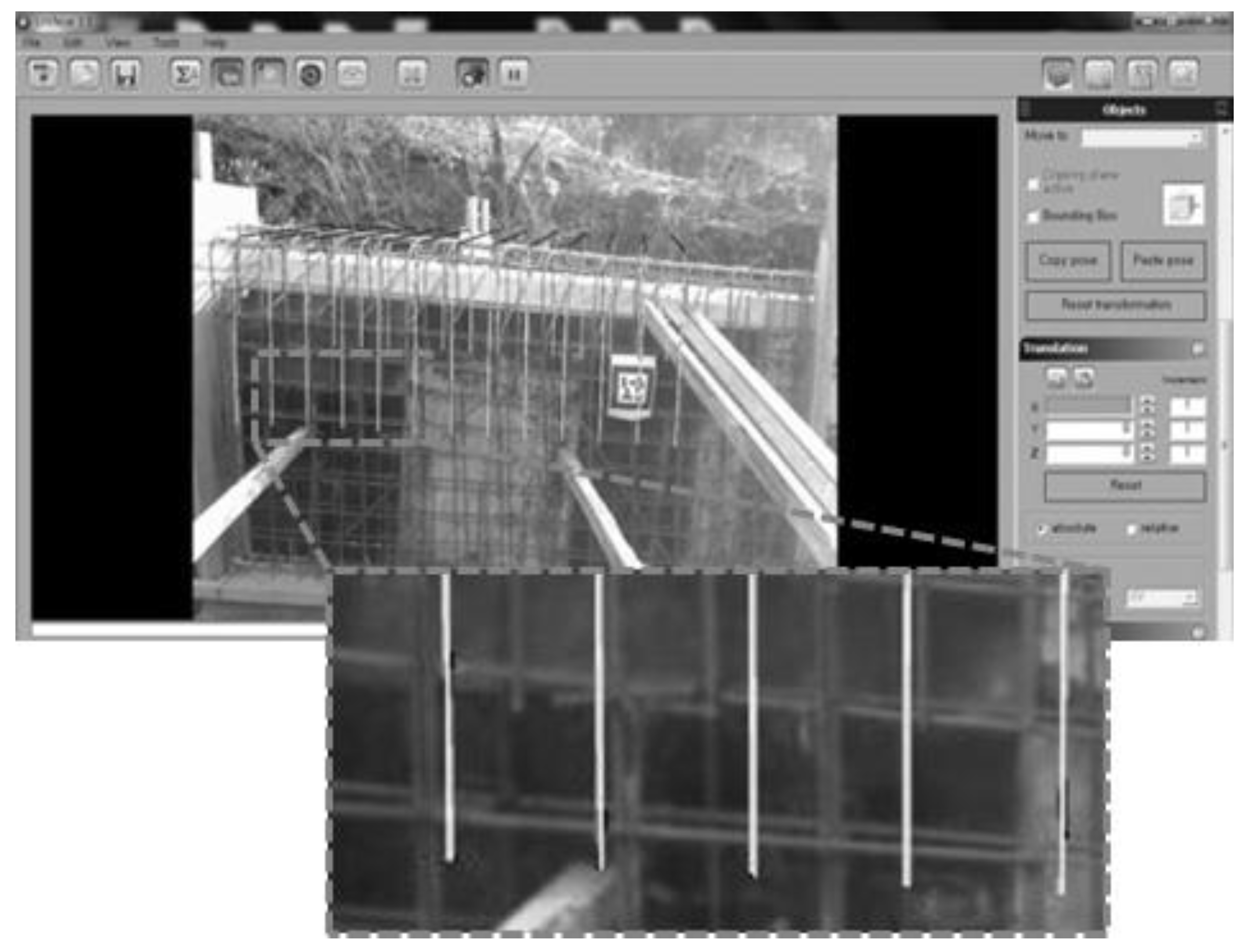
  8. Kim, S.Y.; Kim, H.S.; Moon, H.S.; Kang, M.S. Field Applicability of Augmented Reality Technology by Marker Mapping for Construction Project (Focused on Measurement Process of Rebar Work). J. Korean Soc. Civ. Eng. 2013, 33, 2509–2518. [Google Scholar]
  9. Piroozfar, P.; Boseley, M.S.; Essa, M.A.; Farr, E.R.P.; Jin, R. The application of Augmented Reality (AR) in the Architecture Engineering and Construction (AEC) industry. In Proceedings of the Tenth International Conference on Construction in the 21st Century (CITC-10), Colombo, Sri Lanka, 2–4 July 2018. [Google Scholar]
  10. Kodeboyina, S.M.; Varghese, K. Low cost augmented reality framework for construction applications. In Proceedings of the 33rd International Symposium on Automation and Robotics in Construction, Auburn, AL, USA, 18–21 July 2016; Volume 33, pp. 1–9. [Google Scholar]
  11. Omar, T.; Nehdi, M.L. Data acquisition technologies for construction progress tracking. Autom. Constr. 2016, 70, 143–455. [Google Scholar] [CrossRef]
  12. Kim, J.; Irizarry, J. Assessing the effectiveness of augmented reality on the spatial skills of postsecondary construction management students in the U.S. In Proceedings of the 34th International Symposium on Automation and Robotics in Construction, Taipei, Taiwan, 28 June–1 July 2017; Volume 34, pp. 173–180. [Google Scholar]
  13. Mahmood, B.; Han, S.; Lee, D.E. BIM-Based Registration and Localization of 3D Point Clouds of Indoor Scenes Using Geometric Features for Augmented Reality. Remote Sens. 2020, 12, 2302. [Google Scholar] [CrossRef]
  14. Bikash, L.; Kyosuke, K. Development and Implementation of AR Application for the Advancement of the Tasks in the Construction sites. In KaTRI Annual Report; Kajima Technical Research Institute: Tokyo, Japan, 2019; Volume 67, pp. 160–165. [Google Scholar]
  15. Ricardo, L.M.; Cesar, V. Conceptual Framework for Integrating BIM and Augmented Reality in Construction Management. J. Constr. Eng. Manag. 2020, 26, 83–94. [Google Scholar]
  16. Heo, K.J.; Lee, S.J.; Jung, S.K. A Study of Augmented Reality based Visualization using Shape Information of Building Information Modeling. Spat. Inf. Res. 2012, 20, 1–11. [Google Scholar]
  17. Han, M.Y.; Beak, K.Y.; Lee, K.T.; Ko, S.J.; Kim, J.H. A Study on Supporting Design Decision Making in Office Building Remodeling Projects by Introducing Mixed Reality. Korean J. Constr. Eng. Manag. 2021, 9, 1–9. [Google Scholar]
  18. Lee, M.J.; Lee, H.M.; Lee, I.S.; Nam, S.H. Augmented Reality for Construction Industry: Focused on BIM based Electronic Standard Drawing. J. Korean Soc. Steel Constr. 2017, 29, 12–16. [Google Scholar]
  19. Schiavi, B.; Havard, V.; Karim, B.; David, B. BIM data flow architecture with AR/VR technologies: Use cases in architecture. Autom. Constr. 2022, 134, 104054. [Google Scholar] [CrossRef]
  20. Lee, K.H.; Park, J.W.; Kang, H.J.; Shin, D.H. Seamless Superimposition Technique of Virtual Objects for AR System of Excavator Based on Image Processing. Korean J. Constr. Eng. Manag. 2017, 18, 21–29. [Google Scholar] [CrossRef]
  21. Pham, H.; Nguyen, L.; Lee, Y.J.; Park, M.W.; Song, E.S. Augmented Rality Framework to Visualize Information about Construction Resources Based on Object Detection. J. Korean Inst. Build. Inf. Model. 2021, 11, 45–54. [Google Scholar]
  22. Schall, G.; Zollmann, S.; Reitmayr, G. Smart Vidente: Advances in mobile augmented reality for interactive visualization of underground infrastructure. Pers. Ubiquitous. Comput. 2013, 17, 1533–1549. [Google Scholar] [CrossRef]
  23. Agarwal, S. Review on Application of Augmented Reality in Civil Engineering. In Proceedings of the ICIDRET, Emporium Building, New Delhi, India, 12–13 February 2016. [Google Scholar]
  24. Chalhoub, J.; Ayer, S.K. Perception of industry professionals about Mixed Reality for electrical prefabrication. In Proceedings of the CSCE Annual General Conference, Vancouver, BC, Canada, 31 May–3 June 2017. [Google Scholar]
  25. Chalhoub, J.; Ayer, S.K. Using Mixed Reality for electrical construction design communication. Autom. Constr. 2018, 86, 1–10. [Google Scholar] [CrossRef]
  26. Chu, M.; Matthews, J.; Love, P.E. Integrating mobile Building Information Modelling and Augmented Reality systems: An experimental study. Autom. Constr. 2018, 85, 305–316. [Google Scholar] [CrossRef]
  27. Shin, J.S.; Choi, J.P. Establishment of Integrated Design Bases Management System of APR1400 Using BIM based Algorithm. Korean J. Constr. Eng. Manag. 2019, 20, 52–60. [Google Scholar]
  28. Park, S.Y.; Song, J.H.; Oh, K.S. Development of Construction Schedule Management System based on BIM. Korean J. Architect. Inst. 2018, 34, 61–68. [Google Scholar]
  29. Lee, C.K.; Sin, S.Y.; Issa, R.R. Classification of a Free-Form Surface by Parametric Design and Machine Learning. In Proceedings of the Construction Research Congress, Tempe, AZ, USA, 8–10 March 2020. [Google Scholar]
  30. Yoon, J.W.; Kim, S.S.; Lee, S.H. A Study on the Development of Dynamo Algorithm for Initial Schedule Creation Using BIM-based Space Division. In Proceedings of the KICEM Annual Conference, Seoul, Republic of Korea, 11–12 November 2021. [Google Scholar]
  31. Lee, Y.J.; Kim, J.Y.; Phan, H.; Park, M.W. Augmented Reality Framework for Efficient Access to Schedule Information on Construction Sites. J. Korean Inst. Build. Inf. Model. 2020, 10, 60–69. [Google Scholar]
  32. Chalhoub, J.; Alsafouri, S.; Ayer, S.K. Leveraging Site Survey Points for Mixed Reality BIM Visualization. In Proceedings of the Construction Research Congress 2018, New Orleans, LA, USA, 2–4 April 2018. [Google Scholar]
  33. Kieran, W.M.; Chandani, K.C.; Ochoa, J.J.; Gu, N.; James, W.; Ross, T.S.; Bruce, H.T. The Identification, Development, and Evaluation of BIM-ARDM: A BIM-Based AR Defect Management System for Construction Inspections. Buildings 2022, 12, 140. [Google Scholar]
  34. Kwon, O.S.; Park, C.S.; Lim, C.R. A defect management system for reinforced concrete work utilizing BIM, image-matching and augmented reality. Autom. Constr. 2014, 46, 74–81. [Google Scholar] [CrossRef]
  35. Wang, K.C.; Chao, T.C.; Yu, P.Y. A BIM-based Augmented Reality System for Four-Dimensional Simulation. In Proceedings of the International Symposium on Nondestructive Testing in Civil Engineering, Zurich, Switzerland, 16–18 August 2022; Volume 9. [Google Scholar]
  36. Liu, Y.; Tanudjaja, G.; Jiang, Z.; Beck, N. Workflow of Exporting Revit Models to Unity; Penn State CIC Research Group: University Park, PA, USA, 2016; pp. 22–26. [Google Scholar]
  37. Garbett, J.; Thomas, H.; David, H. A multi-user collaborative BIM-AR system to support design and construction. Autom. Constr. 2021, 122, 103487. [Google Scholar] [CrossRef]
  38. Jeon, H.I.; Ko, B.J.; Kim, S.H.; Lee, K.E.; Yu, Y.S.; Koo, B.S. Establishment of Augmented Reality Based Building Element Information Visualization System using Unity 3D. In Proceedings of the KSCE 2020 Convention, Seogwipo-si, Republic of Korea, 21–23 October 2020. [Google Scholar]
Figure 1. Research procedures and scope.
Sustainability 15 03222 g001
Figure 2. AR application in earthwork stage [18].
Sustainability 15 03222 g002
Figure 3. Graphical scripting for surface classification with Dynamo [29].
Sustainability 15 03222 g003
Figure 4. Rebar measurement by marker-based AR [8].
Sustainability 15 03222 g004
Figure 5. Visualization of member information using Unity [38].
Sustainability 15 03222 g005
Figure 6. Overview of BIM-marker-based CWSS.
Sustainability 15 03222 g006
Figure 7. BIM-marker-based AR system algorithm.
Sustainability 15 03222 g007
Figure 8. Classification method by the work order of each object.
Sustainability 15 03222 g008
Figure 9. Three-dimensional reconstruction and automatic marker creation system by Dynamo.
Sustainability 15 03222 g009
Figure 10. Divide 3D model by zones through Module 1.
Sustainability 15 03222 g010
Figure 11. (a) Implementing a BIM-based AR application, (b) marker recognition through application, and (c) AR visible in the application.
Sustainability 15 03222 g011aSustainability 15 03222 g011b
Table 1. System configuration of software and hardware.
Application Software and HardwareVersionFunction
SoftwareAutodesk Revit2019.2Classifying objects
Autodesk Revit, Dynamo1.3.4Reconstructing BIM 3D model
Generating markers automatically
Autodesk 3ds Max2020.3.6Designating reference coordinates
Unity2020.3.12.f1Creating an application
HardwarePCCPUAMD Ryzen 5 3600Driving system
RAM16.00GB
GPUNVIDIA GeForce GTX 1660 SUPER
Smart DeviceMore than Android 7.0Testing system
Samsung Galaxy S9Android 10.0
Table 2. Reconstructed BIM and auto-generated markers through Module 2.
Schedule of Object & Corresponding Markers
(2)(3)(4)
ZoneObjectOrderCountWork CodeObject IDMarker
BeforeAfter
Zone 1Column140104 Sustainability 15 03222 i001 Sustainability 15 03222 i002 Sustainability 15 03222 i003
1C11C1_0104_1
Beam330104 Sustainability 15 03222 i004 Sustainability 15 03222 i005 Sustainability 15 03222 i006
1B11B1_0104_3
Girder220104 Sustainability 15 03222 i007 Sustainability 15 03222 i008 Sustainability 15 03222 i009
1G11G1_0104_2
Zone 2Column520104 Sustainability 15 03222 i010 Sustainability 15 03222 i011 Sustainability 15 03222 i012
2C12C1_0104_5
Beam730104 Sustainability 15 03222 i013 Sustainability 15 03222 i014 Sustainability 15 03222 i015
2B12B1_0104_7
Girder620104 Sustainability 15 03222 i016 Sustainability 15 03222 i017 Sustainability 15 03222 i018
2G12G1_0104_6
Disclaimer/Publisher’s Note: The statements, opinions and data contained in all publications are solely those of the individual author(s) and contributor(s) and not of MDPI and/or the editor(s). MDPI and/or the editor(s) disclaim responsibility for any injury to people or property resulting from any ideas, methods, instructions or products referred to in the content.

