1. Introduction
In the face of a growing urban population and a warming climate [
1], efficiently constructed, environmentally responsible, and architecturally valuable buildings are vital. Timber construction could address this need [
2,
3,
4,
5], as wood is the only widely used renewable material in construction [
6], especially by substituting other construction materials [
7]. Although the calculations are uncertain [
8,
9], there are more trees now than ever [
10] and the data support the idea that increased wood consumption would not detrimentally affect global forests [
11,
12], growth stocks [
13], or agricultural production [
14].Wood is a renewable material [
15] which sequesters carbon [
16]. Regardless, it must be built with efficiently in order to remain sustainable [
17]. Multi-storey timber buildings (MsTBs) can serve as constructed carbon sinks as long as they are not torn down or replaced [
18,
19]. Buildings are not replaced because they are faulty; rather, they become ’functionally obsolete’, that is, they no longer meet the desired usage [
20,
21,
22]. Therefore, adaptable buildings have more carbon storage capacity.
Conventional timber structures often feature regular structural grids that support beams [
23,
24,
25]. Adaptable structures have flat ceilings and columns with no beams. Punctual supports must be used instead of post-and-beam construction to support the free design of architectural spaces and repositioning of non-bearing interior partitions; however, these are more difficult to detail and fabricate [
26]. Biaxially-spanning Engineered Wood Products (EWPs) such as CLT can help to obtain greater performance from the columns [
27,
28]. These monolithic or semi-monolithic slabs require additional fabrication and assembly considerations.
The exceptional strength-to-weight ratio of wood [
29] means that components are lighter to transport, which is ideal for prefabrication. Almost all recent MsTBs are made using prefabricated Engineered Timber Products (ETPs) [
30], including Mjøstårnet in Norway [
31] and HoHo in Austria [
32]. A subset of EWPs [
33,
34], ETPs have been fundamental in the current renaissance of timber buildings [
35]. ETPs use the strength of wood fibres more efficiently and homogeneously by interconnecting wood-based elements with adhesives [
36], and are produced in highly automated and mechanised processes. A focus on this standardised production over the past twenty years [
37] has produced mostly grid-based rectilinear timber volumes with regular flat extrusions [
38]. There are relatively few exceptions with irregular outlines, such as Bjergsted Financial Park [
39] and Samling Library [
40], both in Norway. These were enabled by more custom design and fabrication methods, as conventional timber construction struggles to adapt to constrained urban sites, non-orthogonal footprints, or atypical programmes.
1.1. Aim
This paper aims to adapt and extend co-design methods to MsTBs.Co-design is the simultaneous and feedback-driven development of both methods and designs while considering multifaceted stakeholder perspectives [
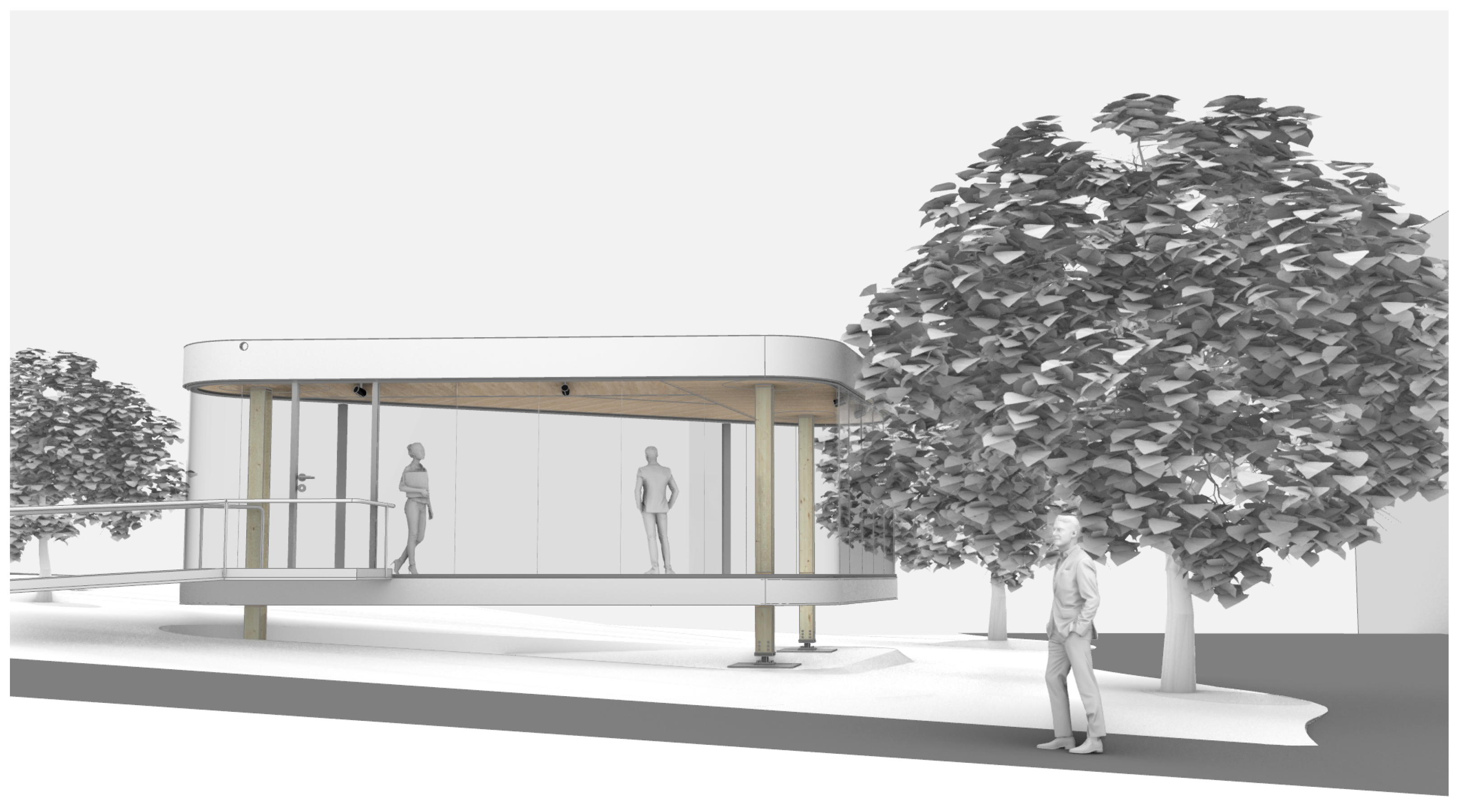
41]. Co-design permits the systematic, holistic, and interdisciplinary integration of computational planning and building techniques for sustainable construction. This article showcases its results through the design and development of a prototype timber building (
Figure 1). When constructed, the prototype is lifted off the floor to test and show a column-to-column joint, the crux of all multi-storey projects. Though short, it exhibits the qualities and details of adaptable multi-storey timber buildings, including flat-bottomed and wide-span semi-monolithic slabs without beams and supported by columns.
1.2. State of the Art
1.2.1. Co-Design
In traditional architectural workflows, as defined by the AIA [
42], RIBA [
43], HOAI [
44], and others, different disciplines contribute their expertise sequentially to a design of increasing resolution. The work moves from one design phase to another along a digital project chain [
45,
46]. Changes that become necessary later in the design process are costly and difficult to implement, especially during construction [
47].
Many project delivery methods have been developed as alternatives to this design–bid–build model. These include design–build, construction management at risk, integrated project delivery (IPD) [
48], and lean project delivery (LPD) [
49,
50]. IPD has gained significant attention, and there have been several studies on its implementation in projects across various scales and geographies [
51,
52,
53]. Although IPD and LPD differ in how their contracts and operational systems integrate lean principles, they are often conflated. They both “seek to involve key participants in early stages and form an integrated project team that works together under an environment of collaboration, open communication, and mutual respect and trust” [
54]. Like co-design, they enable a more integrated planning and development process.
Though digital models in the form of BIM [
55] are often included in the execution of IPD, they are primarily used for the “computerisation” of existing processes and procedures [
56]. The success of BIM relies on the assumption that the exact location, dimension, and specifications of all building elements can be predefined and then executed during construction. However, projects are increasingly complex, and it is not always possible to plan them out in this deterministic way. Design data and the ability to action changes are often lost in the BIM model by the time fabricators begin producing components and contractors begin assembling them on site [
57,
58]. Co-design aims to produce fundamentally new approaches for sustainable construction through the digitisation of the entire building process. Relevant construction and prefabrication stakeholders can contribute data and insights as part of a conceptual co-design process. Depending on implementation, the same design data could be used in the production of the building without translation. As Knippers et al. note, “the linking of methods, processes and systems also lays the foundation for behavior-based, sensor-driven, cyberphysical manufacturing and construction” [
41]. Knippers et. al. emphasise that "opportunities for novel, feedback-driven, robust and semi-autonomous or autonomous construction processes that do not rely on fully pre-planned models but still achieve the required performance and quality" are only possible through a co-design approach [
41]. Co-design addresses barriers to innovation in the construction industry, and has already been tested on other experimental projects [
59]. Moreover, co-design opens up opportunities for broader economic, environmental, and social sustainability thanks to its integration of diverse fields and quality models [
60].
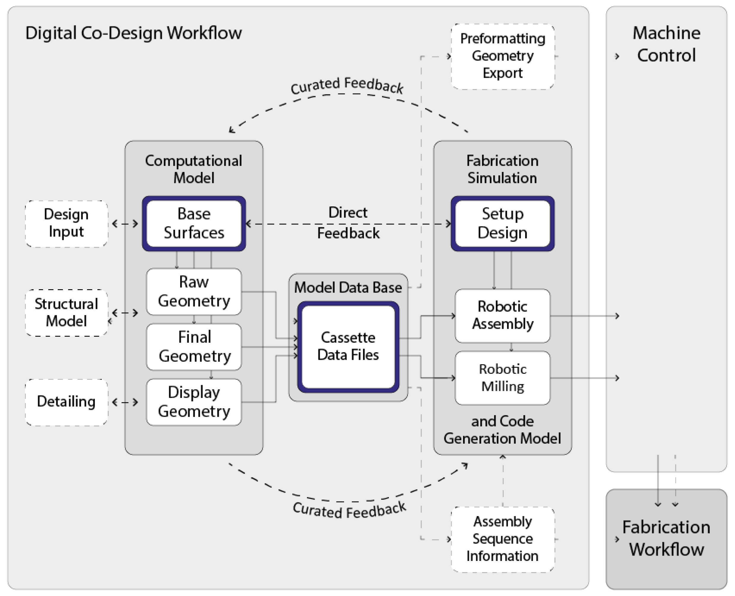
Co-design is especially relevant for MsTBs because of the degree to which material, detail, and manufacturing are related to the built object. It places emphasis on construction processes and fabrication methods during the design process. By digitally integrating manufacturing data into the design model, data can be retained through to construction. Continuous multidirectional feedback between disciplines and stakeholders enables faster iteration and validation of design ideas, as shown in
Figure 2 [
61]. Direct feedback is quantitative, digital, and “allows for reciprocal dependencies between...domains” [
61], such as matching building element sizes to robotic payloads. Curated feedback is qualitative and interpersonal, and is used for parameters that are too complex for computational implementation or that require negotiation and consensus among collaborators, such as fabrication and construction assembly sequencing. Co-design enables the simultaneous solving of heterogeneous criteria, such as maximum performance with minimum material use. In this research, co-design is supported by custom computational tools, for instance using agent-based models (ABMs), that leverage the latest developments in all associated fields.
1.2.2. Agent-Based Models
The many uses of ABMs in architecture can be categorised by what the agents in the model represent [
62]. Following their initial introduction to the field [
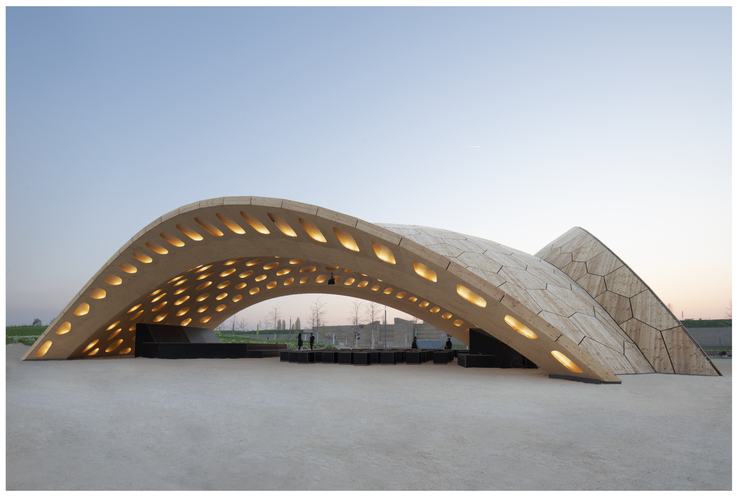
63], they have been used to represent people and stakeholders, physical builders, digital builders, and building elements, among others. The BUGA Wood Pavilion (
Figure 3) used fabrication-informed agent-based segmentation techniques [
64]. The design of our building prototype adapts them for flat-slab multi-storey timber construction. In addition, a computational approach is applied to the arrangement of other structural elements, including columns and reinforcement inside the slab.
1.2.3. Digital Timber Construction
Cyber–physical fabrication techniques have the potential to be environmentally sustainable building production methods [
65,
66]. The use of ABMs and robotic construction in architectural design research have produced timber structures that would have otherwise been impossible [
67,
68]. This collective success leads us to ask how such a digital approach to wood architecture could contribute to better or more affordable buildings [
69]. The flexibility and adaptability of our design and digital fabrication tools is a key concern if construction is to remain resilient in a high-risk and low-profit market [
70]. Potential ideas for extending the capacities of timber construction networks revolve around the strict standardisation and automated prefabrication of (re-useable) parts [
71,
72]. Others focus on the vertical integration of timber building design and production [
73,
74]. Nevertheless, few researchers have focused on the question of how the prevalent and wildly successful point-supported monolithic concrete slab may be replaced with a timber structure having similar qualities [
75,
76,
77]. Although existing research on ways for new technologies to reduce material consumption in concrete slabs is welcome [
78,
79], these solutions do not have the same environmental potential as building with renewable materials.
2. Materials and Methods
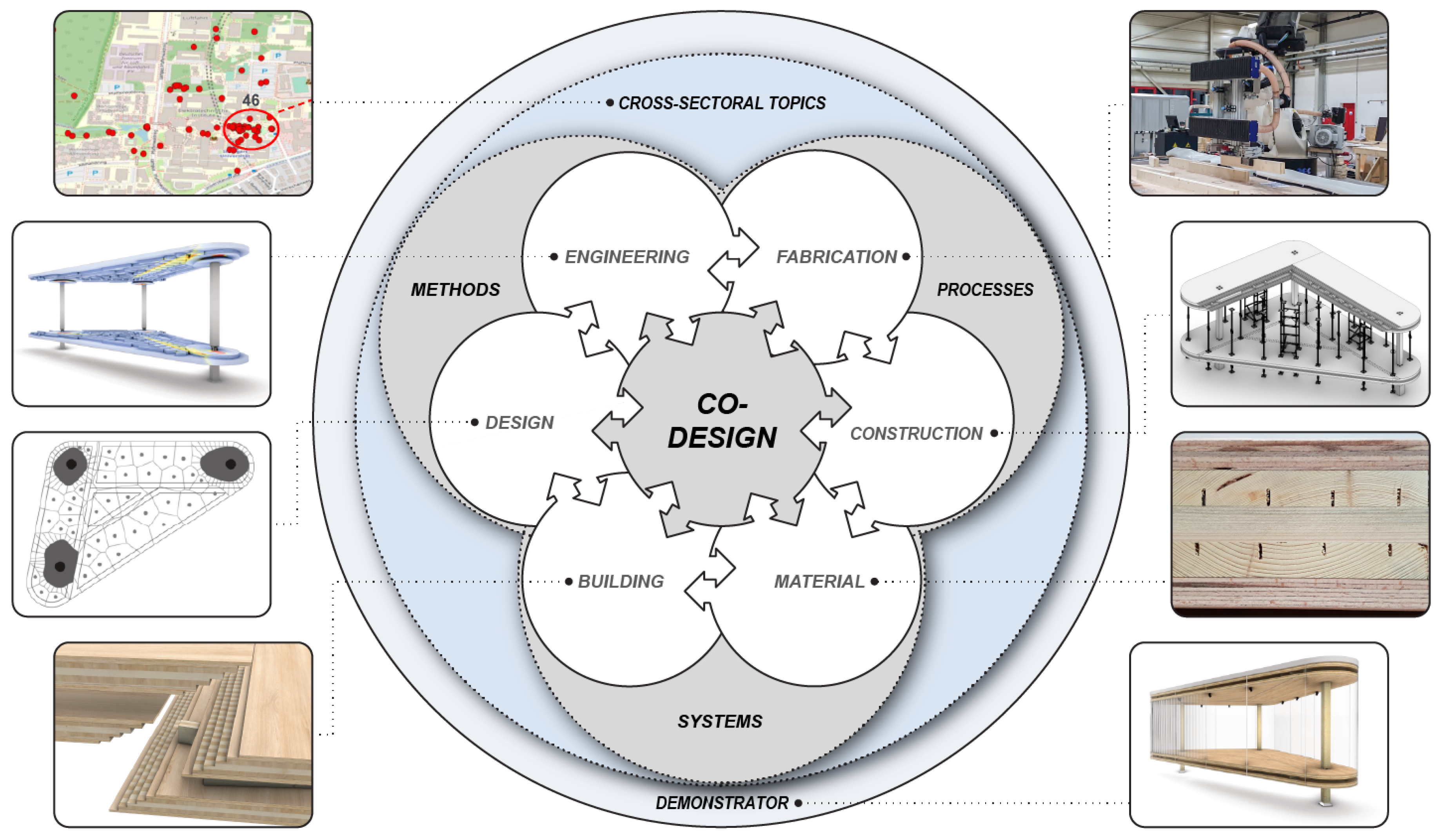
Co-design aims to achieve a higher level of integration and interdisciplinarity [
80] in the building industry through the development of methods, processes, and systems. It supports the ancillary goal of developing building elements that fulfil requirements from different disciplines without adding building layers. The project-specific refined co-design approach is shown in
Figure 4. The systems, methods, and processes therein are explained in the following sections.
2.1. Material Systems
There are various floor systems in contemporary timber construction [
81]. Many are hybrid systems that combine timber with concrete, steel, or both [
82]. All-timber floor assemblies generally fall into one of three categories: solid (such as a sheet of CLT), with reinforcement below (such as ribs or beams), and with reinforcement inside the slab (such as hollow or box systems) [
83]. These approaches were tested in the development of a building system that would leverage the capabilities of robotic fabrication and computational design [
84] and a hollow system utilising interior reinforcement was chosen. The interior components serve two purposes: column crowns strengthen the point where the columns hit the slab, while discrete webs transfer shear between the top and bottom of the slab. Because they are assembled from many anisotropic components, it is possible to tune the physical properties of each timber component in a more material and labor-efficient way than arranging rebar inside a concrete slab [
85].
The majority of wood used for construction in Europe today is Norway spruce (
Picea abies) [
86]. One of the effects of climate change is that the balance of available wood is expected to change from more softwood to more hardwood [
87,
88,
89]. We propose a different type of hybrid building system to take advantage of future timber stocks, namely, a softwood–hardwood hybrid. Softwood is low-density and has a uniform structure, requiring simpler manufacturing technologies for surface treatment and gluing. This results in a more economical fabrication process than for hardwood [
90]. While hardwood is generally stronger [
91], it is more difficult to process than softwood. It must be cut more slowly and is more prone to chipping [
92]. Moreover, certain species of hardwood produce harmful byproducts when machined [
93]. As it is more performative and more difficult to machine, hardwood is used only in areas of high stress. Softwood, being faster to grow and machine [
94], makes up the majority of used material.
2.2. Building Systems
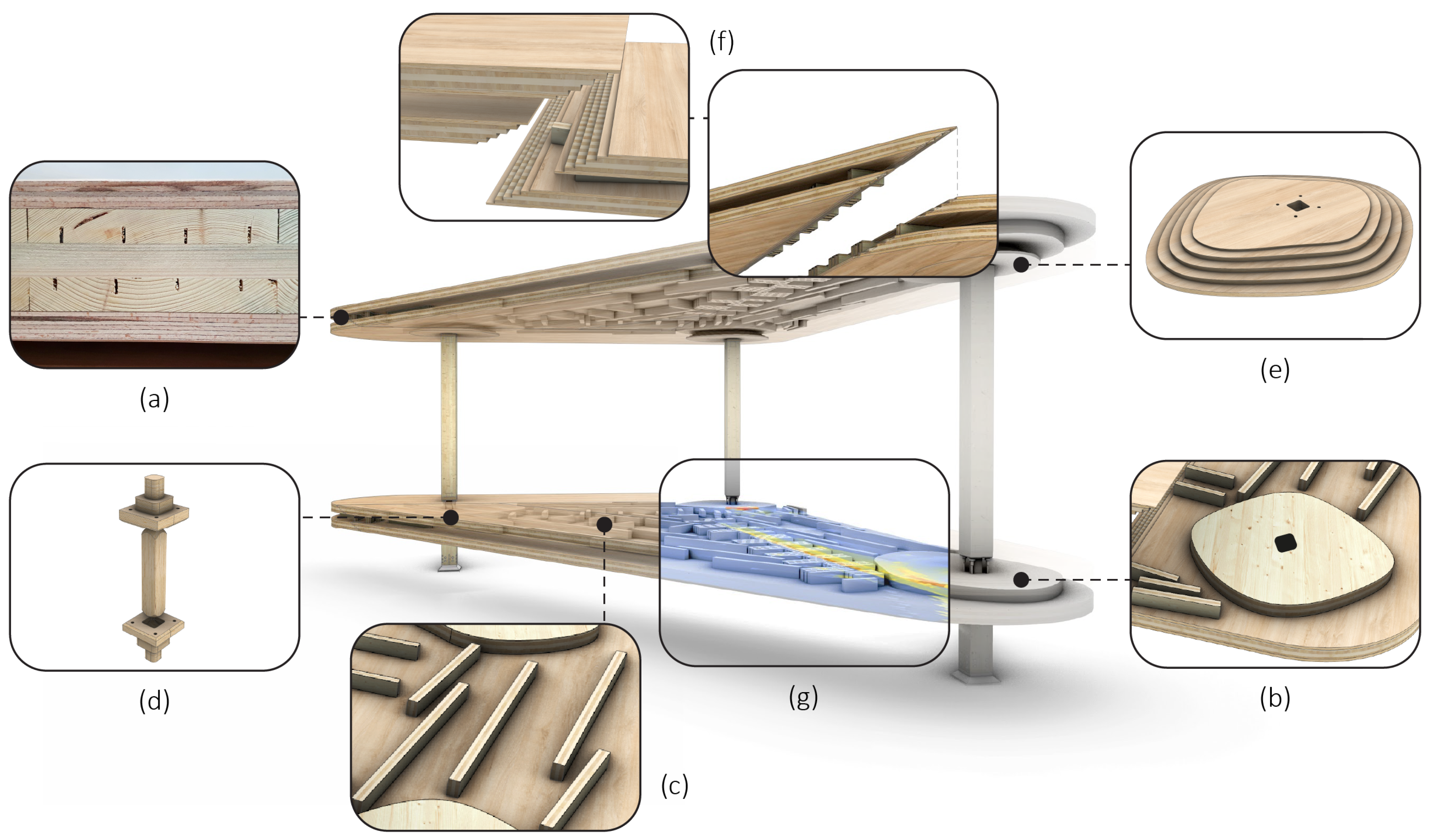
The building system consists of timber slabs and columns (
Figure 5). Walls and bracing systems, with their associated joints and details, are excluded from this development and require additional research. The slab is a sandwich construction with a tailored interior design that considers the forces that occur in the slab. The top and bottom slabs are sandwich panels made of European beech (
Fagus sylvatica) LVL above and a three-layer CLT core of Norway spruce (
Picea abies) below (
Figure 5a). The hardwood LVL panels on the exterior of the hollow system increase its bending performance in the longest spans, while those inside the hollow system protect the softwood from punching shear peaks at the ends of the internal reinforcement. The slab interior consists of column crowns and discrete webs (
Figure 5c). The column crowns reinforce the high shear areas around the column head with a five-layer CLT. The discrete webs can be thought of as internal beams. They serve a similar purpose to the web of a rolled steel joist by providing space between the top and bottom of the slab, and transfer shear in the open span areas. The web components are made of three-layer CLT offcuts from the top and bottom slab. In the building prototype, electrical wiring is placed between webs to avoid a drop ceiling. Alternatively, service provision could influence reinforcement placement. Services could be run inside the slab along its edge, where they are easier to service, although they would not add to the structural depth [
95].
The above system enables adaptability after construction through its architectural qualities. Flat ceilings allow non-load-bearing partitions to be placed at will, which can create different spatial configurations and functions. Open corners increase freedom in planning, as they do not impose fixed boundaries or orientations. Non-orthogonal grids do not prescribe what size of spaces can fit in the building, as they can accommodate various shapes and dimensions. Services integrated in the slab remain in place regardless of building use or partition layout, supporting the adaptability of the building system. These qualities make the system suitable for diverse and changing building programmes and user needs.
Connections play an important role in the development of the building system [
96]. They replace typical steel details with hardwood inserts located where the forces are greatest, which are held together by a novel formaldehyde-free glue (Loctite HB 181 Purbond from Henkel AG). The column-to-column connection uses hardwood pyramid structures at the head and foot of each column to focus vertical forces into a beech LVL pin that runs through a hole in the middle of the column-to-plate connection (
Figure 5d) [
97,
98]. The column-to-plate connection consists of a column crown (
Figure 5b) and a distribution plate (
Figure 5e). The distribution plate is a hardwood pyramid that fits inside the column crown; it protects against punching shear, transfers shear forces, and transfers the bending moments at the column head [
97,
99]. The plate-to-plate connection is a step joint (
Figure 5f) with short connection webs perpendicular to the seam (
Figure 5g). The various connections are described in more detail in [
84].
2.3. Design Methods
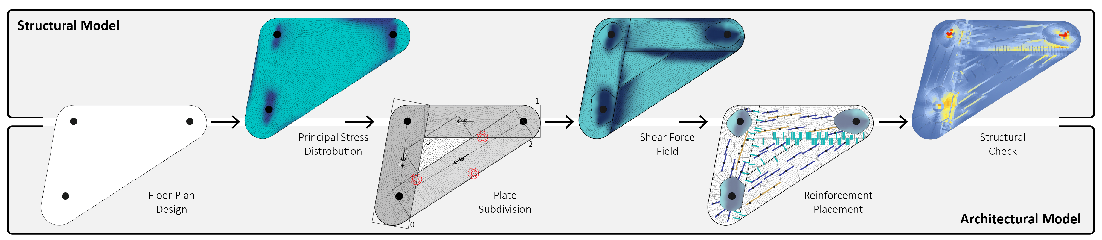
The building prototype demonstrates architectural aspects that are impossible in a conventional timber building system. These include multi-directional spans, open corners, and cantilevers up to two metres, all without beams or orthogonal columns. This required a specialised computational design framework. Structural and fabrication requirements are integrated into the design process (
Figure 6). The segmentation strategy is informed by moment directions in the overall floor slab, and is governed by the maximum prefabricable slab size [
100]. The stepped plate-to-plate connection increases design freedom by joining plates with arbitrary main fibre directions. The column crowns and shear webs that reinforce the slab consider both the structural requirements [
100] and the robotic prefabrication platform. Discretised webs allow for further service integration in the slab. For example, web arrangements can be adapted to the layout of integrated services [
95].
Structural, fabrication, and design considerations were integrated into a single model built on a multi-level, multi-agent simulation in accordance with co-design principles [
100]. The current state of design modelling within the architecture industry lacks an interoperable data standard [
101]. To overcome this deficiency, rather than an IFC model [
102], a global building model using BHoM served as a connection between design and engineering models [
103]. Direct feedback in the form of data links and curated feedback through interpersonal communication were incorporated into the agent simulations that underpin this model. Therefore, changes in the design of the prototype building can be evaluated immediately against all disciplines. As a representative example, timber expertise was incorporated through both direct and curated feedback. Curated feedback preceded the calibration of the simulations, while direct feedback in the form of simulation and experimental results was transferred through linked digital models to reinforce the simulations. Curated feedback was then used again when detailing the prefabrication and construction.
Furthermore, the co-design concept was extended beyond technical topics by considering sociocultural aspects in the early design phase. A survey on potential use and location was created with researchers from the Institute for Social Sciences (SOWI). The purpose of this survey was not to influence the design of the prototype building; rather, it was to inform its use and location. It did, however, provide community engagement for the project and lead to feedback on the prototype building’s design. The survey was distributed by email to all students and employees of the university, and was posted on social media accounts of both the university and the research cluster. In the month during which was open, it was completed by 384 (16%) of the over 2300 hits it received. Locations throughout campus were suggested, most of which were clustered around major thoroughfares. This feedback helped to inform the location of the prototype building. The three most popular usage suggestions were variations on “study space”, “community space”, and “exhibition space”. The building services and amenities of the prototype building, including lighting setup and internet access, were adapted according to the suggested uses.
2.4. Engineering Methods
The engineering and design methods are highly integrated. A global building model informed by structural analysis is central to the co-design method. The elements of the system are refined in a stepwise manner. Based on previous research [
100], the shape of the floor plan was subdivided into plate segments that can be manufactured separately. The segmentation strategy qualitatively considered the shear forces and the principal moment vectors. Plates were arranged according to the force flow and cut according to the shear force hierarchy.
The central model was updated using the simulation results for the segmented plate. Field webs were placed following the method described by [
100,
104], in which a weighted Lloyd algorithm arranges more webs in areas with higher shear [
105]. The field webs were orientated to match the principal moment direction at their location in the slab. Their lengths varied within the given threshold. Additional webs were added to improve the stiffness of the plate-to-plate connection. Connection webs were oriented perpendicular to the seam and had a consistent length of 40 cm. The number of connection webs depended on the shear forces at the connection.
The global structural model was set up in Grasshopper [
106] and sent to SOFiSTiK [
107]. The three slab layers (top, interior, and bottom) were represented through shell elements connected by translation and rotation couplings. Plate-to-plate connections were represented through the stiffness loss in the material definition. The stiffness loss was experimentally verified using tension and shear tests considering the different plate-to-plate connection angles [
108]. Furthermore, the column-to-column connection has previously been simulated and physically tested [
109,
110]. Based on the concept by Tapia et al. [
97], the column-to-plate connections were geometrically adapted to the shear forces.
The column-to-plate connection cannot be represented properly in the global structural model; therefore, it required a detailed simulation. The column-to-plate connection was simulated as a 3D finite element model in Abaqus [
111]. A data link was established between Abaqus and SOFiSTiK, which was used for the global simulation. This data link enabled the transfer of global loading conditions to the detail model for verification.
In addition to its own weight, the timber building prototype is exposed to wind and live loads. For the moment, the lateral loads are transferred through the columns and respective connections to the foundations. The building prototype’s design could be realised without additional lateral bracing, as the lateral loads are transferred through the column and foundation connections. Therefore, lateral wind load requirements were not included in the current co-design approach. Column-to-column connections were reinforced with glued-in threaded steel rods that transfer moment forces caused by lateral loads. The lower column foot was connected to the concrete foundation with a welded steel profile that transfers the moment forces into the foundation [
108]. If a core or other bracing system were present, the column-to-column connections would not need to transfer moments, and hinged connections could be used without the additional steel rods. Additions or extensions to the building system would be required if this co-design method were to be applied to larger test cases with building cores.
2.5. Fabrication Processes
The timber building prototype was co-designed under continuous consideration of the fabrication requirements of the building system and the capabilities of the prefabrication setup. All parts of the timber building prototype, from the size of the steps inside the column joints to the global form, were designed with a direct feedback link to the fabrication system. They were also verified on both the macro- and microscales by timber engineers and structural engineers using direct and curated feedback.
The fabrication and customisation of the hybrid hardwood LVL/softwood CLT plates was defined and then outsourced to a CLT manufacturer. This manufacturer had a large-scale CNC mill and was skilled in the lamination of structural hardwood. Milling tolerances for these components were part of the contract with the manufacturer.
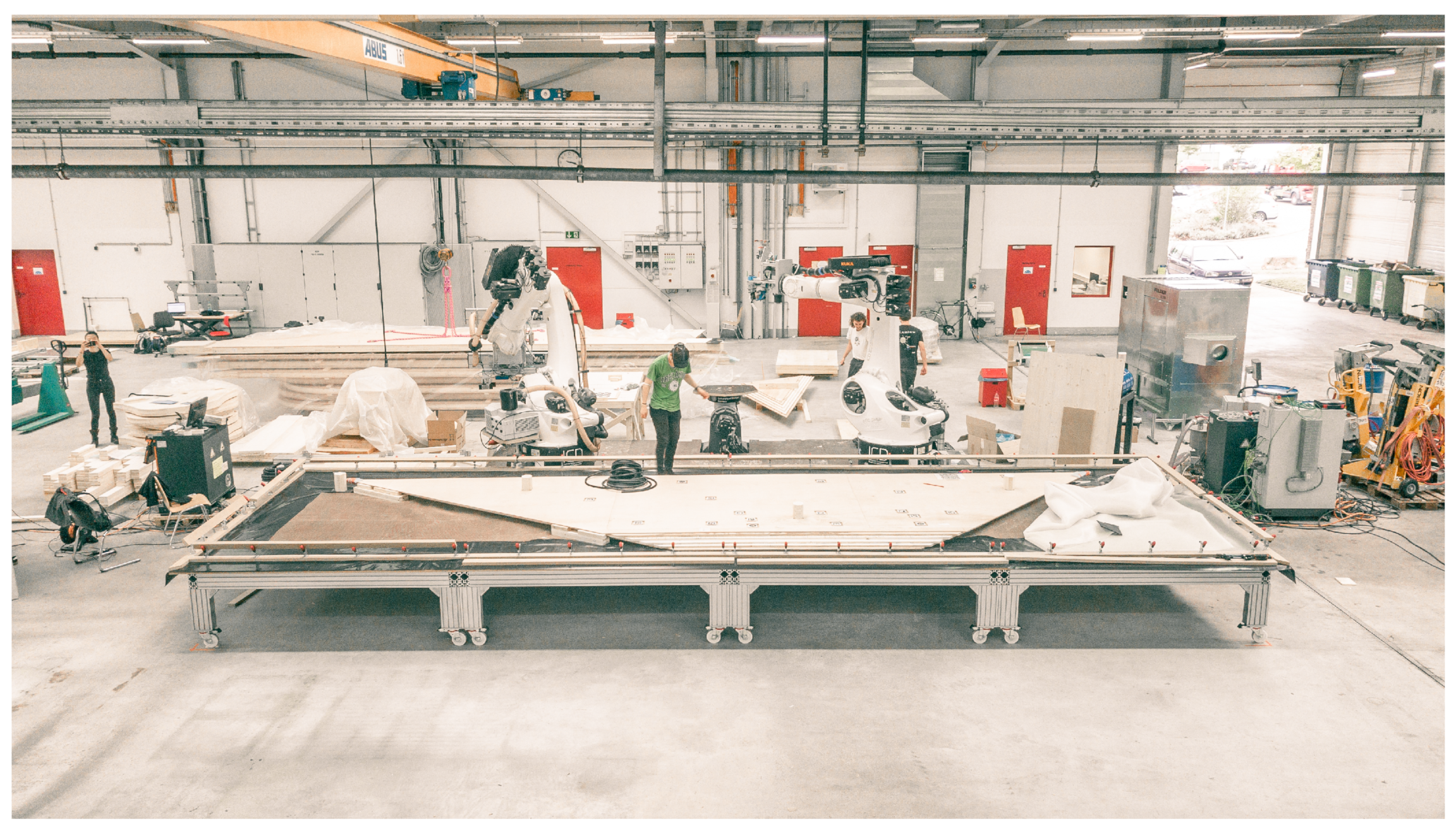
Prefabrication took place on a fabrication platform consisting of two KUKA KR-500 industrial robot arms equipped with several custom end effectors [
70]. One robot was used for the additive fabrication steps, such as the pick and place operation of the shear webs and column crowns. The other robot was used for glue application. Pins between the top and bottom slab layers avoided accumulation of tolerances during the fabrication of sandwich elements. As can be seen in
Figure 7, this fabrication platform was extended in three ways to fulfill the new fabrication requests:
A 3 × 10 m multifunctional mobile fabrication table was developed for the prefabrication of the eight slab elements, which themselves ranged in size from 1.37 × 3.40 m up to 2.10 × 8.90 m. The table could be moved freely through the fabrication hall or attached to a rail on the robotic platform on its heavy duty casters. This table functioned as a manually operable linear axis during prefabrication, as a vacuum press after gluing and placing components, and as a transport for assemblies beyond the payload and reach constraints of the fabrication hall’s gantry cranes.
RGB-D Cameras were used for marker-based workpiece calibration after each manual repositioning of the fabrication table to ensure accurate fabrication execution.
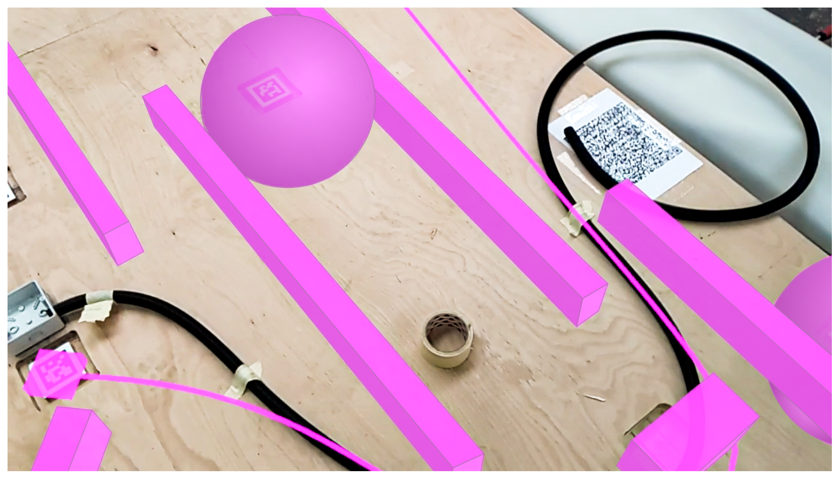
Augmented reality head-mounted displays were used in several ways during fabrication (
Figure 8). This extended the skillset of human workers by visually representing workpieces’ digital twins, enabling a variety of tasks based on otherwise invisible information. These tasks included the application of a glue primer only in areas where it would be needed, the manual application of glue and manual placement of shear webs beyond the reach of the robots, and the laying of electrical conduit in an invisible maze around the unplaced shear webs.
In collaboration with the Visualization Research Centre (VISUS), the placement of electrical conduit within the slab was used as a case study to assess the usability of AR in real-world scenarios. While showing guidance visualisation in AR is not novel [
112,
113], setting the case study within a live prefabrication workflow allowed users who were experienced in such environments to evaluate the visualisations. Standard usability questionnaires that included questions about comfort and utility were filled out by users before and after performing tasks. The results of these questions can help to inform future research aspects, including which tasks should be done, how data are displayed, how building services are integrated into the building system, and how human collaboration is integrated into the prefabrication process.
The semi-autonomous prefabrication of the timber elements combined high and low Levels of automation processes, including both industrial robotics and human craft. The concept of instructive human–robot collaboration was used to distribute fabrication tasks between humans and the robotic fabrication system [
114]. A direct link between the design geometry and the automatic generation of tool paths for in-the-loop automated fabrication was established, aiding in the curated feedback of automation data during the co-design process. This algorithm resulted in a time-saving fabrication sequence by aiming for a minimum number of positions for the mobile fabrication table based on the reach of both robots. The fabrication workflow itself was controlled by a human using custom augmented-reality robot control supervision software called VIZOR [
115]. Tasks were passed ‘on the fly’ between the different actors, i.e., human workers and industrial robots, enabling the fabrication workflow to react to unplanned events and to correct mistakes.
Fabrication tolerances did not affect the global form of the prototype building; instead, they were incorporated into the design of individual functional assemblies. One example is the way in which field webs that were placed too close together by the algorithm were merged as part of the design process [
104]. Connection webs were not affected by this process, as their number and density were defined by structural necessity. Another example is the definition of the size and mass of the column crowns based on the vacuum gripper’s area and payload. One of the specific weaknesses of the building system and its joints is that they do not accommodate tolerances well. As such, a further study is planned to investigate tolerance effects and mitigation strategies.
2.6. Construction Processes
When built, the construction of the ITECH Campus Lab will test aspects relevant for on-site assembly and the performance of on-site joints. Joints relevant for on-site assembly include slab-to-slab joints, column-to-slab joints, and column-to-column connections. These joints were designed as softwood–hardwood hybrids to avoid steel details. Moreover, they were designed to ensure that their on-site assembly vectors would be vertical in order to permit the use of conventional cranes, which simplifies and expedites construction. In addition, all joints needed to be designed with considerable tolerance in order to account for changing environmental conditions during the multi-story construction process. Assembly tolerances caused by dimensional changes in the construction assemblies were considered implicitly. Moisture content changes in the wood were avoided because of the prototype nature of the research object. Therefore, assembly was planned with the expectation that it would occur only in dry weather. Minor tolerances up to 1.5 mm were accounted for using a gap-filling glue provided by the project partners. The accuracy of the construction will be verified when it is complete.
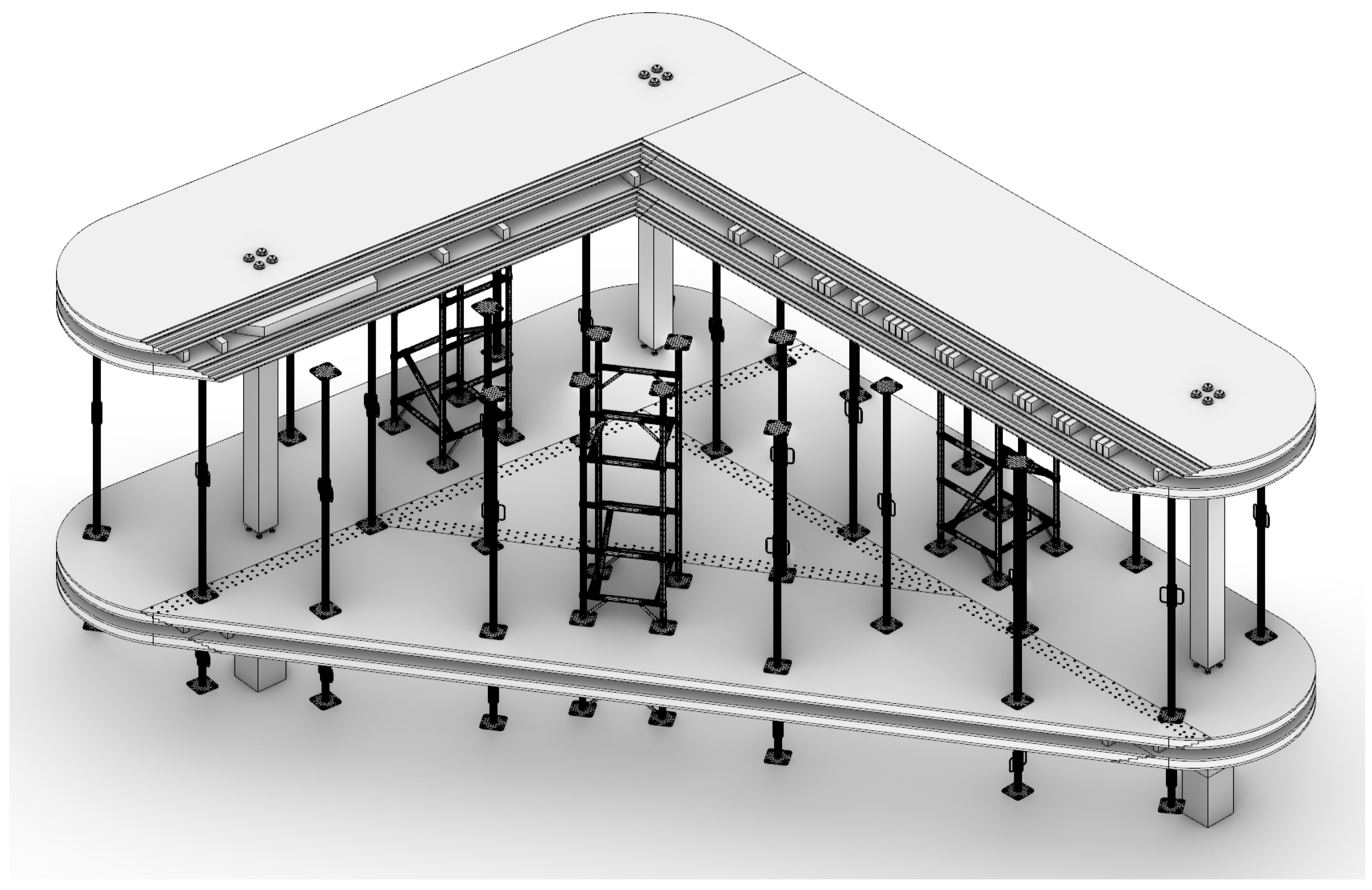
The column-to-slab and column-to-column joints only need to be aligned and fitted. Meanwhile, the slab-to-slab connection presents additional challenges. All internal layers of various densities and fibre directions must be connected with homogeneous stiffness gradients across jointing seams. This will be achieved by using the stepped lap-joint in combination with an on-site screw-press gluing process. The up–down orientation of each joint was set according to the assembly sequence. This allows for relatively straightforward assembly on site, in which one plate after the other is lifted into place by a conventional crane. Both glue application and screw-pressing will be performed manually when the building prototype is assembled. However, their conceptualisation considers the possibility of on-site automation. Future research could investigate tools and methods for on-site screw-press gluing. During the assembly of the structure, plates will be held in place using conventional scaffolding (
Figure 9). Because the building prototype is quite small, there is no plan to use digital tools or workflows to coordinate its construction.
On the top slab, when the plates have been connected and screwed, electricians will be able to reach through the integrated access holes to connect the pre-installed electrical conduit to the junction boxes. From these same access holes, the threading of electrical cables from the insertion point at the column head to the light fixtures will be monitored. An advantage of structural systems such as this is that they can support normal curtain walls and do not require structurally performative facades. When the plates have been assembled and the edge of the slab sealed, a general contractor will install standard interior flooring, facade, and roofing. These will serve as a rain cover to protect the building prototype. As the building prototype is not intended as a demonstration of facade technology or connections, the integration of facade technologies, including high-performance facades, is beyond the scope of the project.
3. Results
The integrative design approach has been developed on two levels, namely, the design of the building system and the design of the building prototype itself. In a first step, the system development integrates structural and fabrication requirements in the design process. In a second step, the building design requires further integration to take the next step from the component level to the building level.
The prototype building serves as a case study for the developed timber building system employing the described co-design methods. All construction assemblies were prefabricated and individually verified in December 2021. The building prototype will be assembled on-site along a key artery of the University of Stuttgart Vaihingen campus in the near future. The prototype consists of eight slab components and six GLT columns. The slab components weigh 144 kg/m2, comprising a floor area of 37 m2 and a maximum slab span of 8.00 m. The digital design of the slab components enabled a high degree of prefabrication. High-precision CNC milling of slab-to-slab and slab-to-column connections, screw holes, and marker positions should result in fast assembly despite the on-site gluing process. The building prototype was designed as a section of a multi-storey building, which could be extended vertically using the same building system. It is deliberately raised off the floor to show its column-to-column joint. The demonstrator building will include a polycarbonate façade and larch roof cladding.
The prototype building was designed in the Rhino/Grasshopper 3D modelling environment [
106]. Design data were stored as BHoM objects in JSON files [
103]. Structural simulations were performed in SOFiSTiK [
107]. This was controlled using the VIZOR augmented reality framework [
115]. Prefabrication relied on the TIM robotic construction platform [
70].
4. Discussion
The building prototype demonstrates an innovative building system that utilises the potential of co-design methods for multi-storey timber construction. Through an inductive approach, this case study can be used to identify larger considerations in the development or application of a co-design methodology in architecture. This methodology allowed for an integrated approach to the design, engineering, fabrication, and construction of the presented timber building system. It incorporated reciprocal relationships among different disciplines throughout the various project stages. As projects increase in scale, they increase in complexity as well. The simulation approaches used here need to be more robust in order to negotiate and optimise between additional disciplines and their expectations. However, high-resolution simulations may not be applicable to all buildings due to cost and time constraints. Further research into computational co-design methodologies is needed to address concerns around scalability.
The novel building system employs specific combinations of hardwood and softwood, as well as mono-material glued joining techniques to enable high-performing and punctually supported floor slabs with multi-axial load transfer and variable spans. This structural system particularly targets non-standard building shapes and volumes, as irregularly shaped buildings are needed to fit into the existing urban fabric. However, this does not consider all of the structural elements of a full multi-story structure. The building system used in this case study would require extensions such as approaches to lateral bracing. If this building system were used for the densification of urban structures, it would need to be tested for building stock extension.
Impact sound transmission is a known issue in lightweight timber structures, and flanking sound transmission is a common problem in hollow box slab systems [
116]. Both of these issues require further study in future work.
Although the building prototype incorporated electrical conduits into the slab, much work is required to turn a structural system into an inhabitable building. Svatoš-Ražnjević et al. [
95] have shown in initial studies how mechanical, ventilation, electrical, and data services could fit inside a hollow slab system. The integration of additional building services, including plumbing, ventilation, and telecommunications, to name a few, requires further investigation. This includes any required service shafts and the considerations around building physics, not the least of which is fire. Conventional mass timber fire safety guidelines that state that all potential openings in the hollow interiors of box slabs must be closed and protected to ensure that they act as completely separate fire compartments [
117]. Integrated electrical conduits have their own inherent fire risk, which future studies should analyse in order to develop standard guideline-compliant solutions accordingly. Fire was considered when determining the dimensions of the slabs and columns, and extra mass for charring was considered in the simulations. It is not adequately understood how the novel formaldehyde-free glue protects against fire.
The inclusion of non-structural elements, such as non-load-bearing partition walls, requires additional investigation as well. The building physics effects of integrating high-performance facades into the system are particularly important for the environmental performance of potential future buildings, as both partitions have an effect on the adaptability of the structure and its continued existence as a carbon reserve.
The presented building prototype capitalizes on the potential of digital fabrication using highly precise additive and subtractive manufacturing processes, enabling customized column and slab building elements by means of standardized timber materials and products. Determining whether the processes used in its production can be successfully scaled up will require additional testing and research.
5. Conclusions
This paper describes an integrated approach to the computational design and development of multi-story timber buildings. The methods described herein are divided into six research areas, and a thorough description of the relevant innovations is provided for each:
Material system
Building system
Design methods
Engineering methods
Fabrication processes
Construction processes
A prototype building is presented as a case study for the co-design methodology. It has flat ceilings, integrated services, wide spans, and the ability to adapt to irregular column layouts. This was achieved by integrating various disciplinary specifications into several computational design methods, including agent-based simulations. A global building model served as the central data node through which discipline-specific data and criteria were collected. Beyond the limited scope of this prototype building, as the size and complexity of timber buildings increases, such design, analysis, and evaluation will become increasingly significant. Further structural considerations such as lateral bracing and cores and building physics concerns such as service integration, building performance, and acoustics all require further investigation. It is only with design approaches and tools such as these that environmentally responsible construction of buildings of sufficient quality can become achievable in a world that is both warming and densifying.
Author Contributions
Conceptualization, H.J.W., A.M. and J.K.; methodology, A.K., H.J.W., L.O., S.B. and F.A.; software, L.O. and F.A.; validation, F.A., A.M. and J.K.; formal analysis, A.K., H.J.W., L.O., S.B. and F.A.; investigation, A.K., H.J.W., L.O., S.B. and F.A.; resources, F.A., A.M. and J.K.; data curation, A.K., S.B. and F.A.; writing—original draft preparation, L.O.; writing—review and editing, A.K., H.J.W., S.B., F.A., J.K. and A.M.; visualization, L.O., A.K. and F.A.; supervision, J.K. and A.M.; project administration, F.A., A.M. and J.K.; funding acquisition, J.K. and A.M. All authors have read and agreed to the published version of the manuscript.
Funding
This research was partially supported by the Deutsche Forschungsgemeinschaft (DFG, German Research Foundation) under Germany’s Excellence Strategy—EXC 2120/1–390831618. The project was made possible by Pollmeier Massivholz GmbH & Co.KG, Zublin AG, Müller Blaustein HolzBauWerke GmbH, Henkel AG, HECO-Schrauben GmbH & Co. KG, CARLISLE Construction Materials GmbH, and Bauservice Ralf Vogt GmbH.
Institutional Review Board Statement
Not applicable.
Informed Consent Statement
Not applicable.
Data Availability Statement
No new data were created or analyzed in this study. Data sharing is not applicable to this article.
Acknowledgments
The ITECH Campus Lab was developed within the scope of the “Integrative Technologies and Architectural Design Research” (ITECH) offered by ICD and ITKE at Stuttgart University. The following students played an indispensable role in the scientific development, design, and fabrication of the project: Kiril Bejoulev, TzuYing Chen, Ryan Daley, Takwa ElGammal, Grant Galloway, August Lehrecke, Daniel Locatelli, Madie Rasanani, Parisa Shafiee, Anand Shah, Lior Skoury, Cody Tucker, Xiliu Yang, Max Zorn, Ingo Haller, Francesca Maisto, Nils Opgenorth, Ekin Sahin, Lorin Samija, Lena Strobel, Håkon Toth, Simon Treml, Julian Trummer, with support from Omar Abdelhady, Yousef Elshafie, Pai-Yi Huang, Xinyou Kou, Jiaxin Li, Simon Reuter, Alice Roy. Special thanks to Research Associate Daniel Sonntag. The authors would also like to thank the following investigators: Cristobal Tapia and Simon Aicher of the Materials Testing Institute (MPA); Theresa Müller and Philip Leistner of the Institute for Acoustics and Building Physics (IABP); Aimee Sousa Calepso and Michael Sedlmair of the Visualization Research Center (VISUS); and Johannes Nöldeke and Cordula Kropp of the Institute for Social Sciences (SOWI).
Conflicts of Interest
The authors declare no conflict of interest. The funders had no role in the design of the study, in the collection, analysis, or interpretation of data, in the writing of the manuscript, or in the decision to publish the results.
Abbreviations
The following abbreviations are used in this manuscript:
| EWP | Engineered Wood Product |
| CLT | Cross-Laminated Timber |
| LVL | Laminated Veneer Lumber |
| GLT | Glue-Laminated Timber |
| IPD | Integrated Project Delivery |
| LPD | Lean Project Delivery |
| ABM | Agent-Based Modeling |
| ABMs | Agent-Based Models |
| CNC | Computer Numerical Control |
References
- UN DESA. World Urbanization Prospects: 2018: Highlights; United Nations: New York, NY, USA, 2019. [Google Scholar]
- González-Retamal, M.; Forcael, E.; Saelzer-Fuica, G.; Vargas-Mosqueda, M. From Trees to Skyscrapers: Holistic Review of the Advances and Limitations of Multi-Storey Timber Buildings. Buildings 2022, 12, 1263. [Google Scholar] [CrossRef]
- Upton, B.; Miner, R.; Spinney, M.; Heath, L.S. The greenhouse gas and energy impacts of using wood instead of alternatives in residential construction in the United States. Biomass Bioenergy 2008, 32, 1–10. [Google Scholar] [CrossRef]
- Hurmekoski, E.; Jonsson, R.; Nord, T. Context, drivers, and future potential for wood-frame multi-story construction in Europe. Technol. Forecast. Soc. Change 2015, 99, 181–196. [Google Scholar] [CrossRef]
- Churkina, G.; Organschi, A. Will a Transition to Timber Construction Cool the Climate? Sustainability 2022, 14, 4271. [Google Scholar] [CrossRef]
- Bourbia, S.; Kazeoui, H.; Belarbi, R. A review on recent research on bio-based building materials and their applications. Mater. Renew. Sustain. Energy 2023, 12, 117–139. [Google Scholar] [CrossRef]
- Abed, J.; Rayburg, S.; Rodwell, J.; Neave, M. A Review of the Performance and Benefits of Mass Timber as an Alternative to Concrete and Steel for Improving the Sustainability of Structures. Sustainability 2022, 14, 5570. [Google Scholar] [CrossRef]
- O’Brien, M.; Bringezu, S. Assessing the Sustainability of EU Timber Consumption Trends: Comparing Consumption Scenarios with a Safe Operating Space Scenario for Global and EU Timber Supply. Land 2017, 6, 84. [Google Scholar] [CrossRef]
- Pasternack, R.; Wishnie, M.; Clarke, C.; Wang, Y.; Belair, E.; Marshall, S.; Gu, H.; Nepal, P.; Dolezal, F.; Lomax, G.; et al. What Is the Impact of Mass Timber Utilization on Climate and Forests? Sustainability 2022, 14. [Google Scholar] [CrossRef]
- Song, S.S.; Fei, B. The psychological effects of different types of housing environment under different weather conditions. Wood Res. 2016, 61, 105–120. [Google Scholar]
- Nepal, P.; Johnston, C.M.T.; Ganguly, I. Effects on Global Forests and Wood Product Markets of Increased Demand for Mass Timber. Sustainability 2021, 13, 13943. [Google Scholar] [CrossRef]
- Comnick, J.; Rogers, L.; Wheiler, K. Increasing Mass Timber Consumption in the U.S. and Sustainable Timber Supply. Sustainability 2022, 14, 381. [Google Scholar] [CrossRef]
- UNECE/FAO. Forest Sector Outlook Study 2020–2040; United Nations: New York, NY, USA, 2021. [Google Scholar]
- Mishra, A.; Humpenöder, F.; Churkina, G.; Reyer, C.P.O.; Beier, F.; Bodirsky, B.L.; Schellnhuber, H.J.; Lotze-Campen, H.; Popp, A. Land use change and carbon emissions of a transformation to timber cities. Nat. Commun. 2022, 13, 4889. [Google Scholar] [CrossRef]
- Ramage, M.H.; Burridge, H.; Busse-Wicher, M.; Fereday, G.; Reynolds, T.; Shah, D.U.; Wu, G.; Yu, L.; Fleming, P.; Densley-Tingley, D.; et al. The wood from the trees: The use of timber in construction. Renew. Sustain. Energy Rev. 2017, 68, 333–359. [Google Scholar] [CrossRef]
- Nabuurs, G.J.; Lindner, M.; Verkerk, P.J.; Gunia, K.; Deda, P.; Michalak, R.; Grassi, G. First signs of carbon sink saturation in European forest biomass. Nat. Clim. Change 2013, 3, 792–796. [Google Scholar] [CrossRef]
- Oliver, C.D.; Nassar, N.T.; Lippke, B.R.; McCarter, J.B. Carbon, Fossil Fuel, and Biodiversity Mitigation With Wood and Forests. J. Sustain. For. 2014, 33, 248–275. [Google Scholar] [CrossRef]
- Churkina, G.; Organschi, A.; Reyer, C.P.O.; Ruff, A.; Vinke, K.; Liu, Z.; Reck, B.K.; Graedel, T.E.; Schellnhuber, H.J. Buildings as a global carbon sink. Nat. Sustain. 2020, 3, 269–276. [Google Scholar] [CrossRef]
- Hurmekoski, E.; Seppälä, J.; Kilpeläinen, A.; Kunttu, J. Contribution of Wood-Based Products to Climate Change Mitigation. In Forest Bioeconomy and Climate Change; Managing Forest Ecosystems; Hetemäki, L., Kangas, J., Peltola, H., Eds.; Springer: Berlin, Germany, 2022; Volume 42, pp. 129–149. [Google Scholar] [CrossRef]
- Langston, C.; Wong, F.K.; Hui, E.C.; Shen, L.Y. Strategic assessment of building adaptive reuse opportunities in Hong Kong. Build. Environ. 2008, 43, 1709–1718. [Google Scholar] [CrossRef]
- Bullen, P.; Love, P. Factors influencing the adaptive re–use of buildings. J. Eng. Des. Technol. 2011, 9, 32–46. [Google Scholar] [CrossRef]
- Kohler, N.; Yang, W. Long-term management of building stocks. Build. Res. Inf. 2007, 35, 351–362. [Google Scholar] [CrossRef]
- Salvadori, V. The Development of a Tall Wood Building. Master’s Thesis, Politecnico di Milano, TU Wien, Milano, Italy, 2017. [Google Scholar]
- Salvadori, V. Worldwide Structural Survey of 197 Multi-Storey Timber- Based Buildings from 5 to 24-Storeys. In Proceedings of the World Conference on Timber Engineering, Santiago, Chile, 9–12 August 2020. [Google Scholar]
- Salvadori, V. Multi-Storey Timber-Based Buildings: An International Survey of Case-Studies with Five or More Storeys Over the Last Twenty Years. Ph.D. Thesis, TU Wien, Wien, Austria, 2021. [Google Scholar] [CrossRef]
- Zumbrunnen, P. Pure CLT—Concepts and Structural Solutions for Multi Storey Timber Structures. In Proceedings of the Internationales Holzbau Forum, Zurich, Switzerland, 30 November–2 December 2022; pp. 1–6. [Google Scholar]
- Muster, M.; Frangi, A. Experimental analysis and structural modelling of the punching behaviour of continuous two-way CLT flat slabs. Eng. Struct. 2020, 205. [Google Scholar] [CrossRef]
- Wei, P.; Wang, B.J.; Li, H.; Wang, L.; Peng, S.; Zhang, L. A comparative study of compression behaviors of cross-laminated timber and glued-laminated timber columns. Constr. Build. Mater. 2019, 222, 86–95. [Google Scholar] [CrossRef]
- Foster, R.M.; Ramage, M.H. Briefing: Super tall timber – Oakwood Tower. Proc. Inst. Civ. Eng. Constr. Mater. 2017, 170, 118–122. [Google Scholar] [CrossRef]
- Bhandari, S.; Riggio, M.; Jahedi, S.; Fischer, E.C.; Muszynski, L.; Luo, Z. A review of modular cross laminated timber construction: Implications for temporary housing in seismic areas. J. Build. Eng. 2023, 63, 105485. [Google Scholar] [CrossRef]
- Abrahamsen, R. Mjøstårnet—Construction of an 81 m tall timber building. In Proceedings of the Internationales Holzbau Forum, Garmisch-Partenkirchen, Germany, 6–8 December 2017; pp. 1–12. [Google Scholar]
- Woschitz, R. Holzhochhaus HoHo Wien: HoHo Vienna—The technical solution. In Proceedings of the Internationales Holzbau Forum, Garmisch-Partenkirchen, Germany, 29 November–1 December 2015; pp. 1–7. [Google Scholar]
- Hugues, T.; Steiger, L.; Weber, J. Timber Construction: Details, Products, Case Studies; Detail Praxis; Birkhäuser and Edition Detail: Basel, Switzerland, 2004. [Google Scholar]
- Niemann, A. Solid wood and wood-based products. In Manual of Multi-Storey Timber Construction; Edition Detail; Kaufmann, H., Krötsch, S., Winter, S., Eds.; Detail Business Information: Munich, Germany, 2018; pp. 18–23. [Google Scholar]
- Krötsch, S.; Müller, L. The development of multi-storey timber construction. In Manual of Multi-Storey Timber Construction; Edition Detail; Kaufmann, H., Krötsch, S., Winter, S., Eds.; Detail Business Information: Munich, Germany, 2018; pp. 10–13. [Google Scholar]
- Milner, H.R. Sustainability of engineered wood products in construction. In Sustainability of Construction Materials; Elsevier: Amsterdam, The Netherlands, 2009; pp. 184–212. [Google Scholar] [CrossRef]
- Barbosa, F.; Woetzel, J.; Mischke, J. Reinventing Construction: A Route of Higher Productivity; McKinsey Global Institute: San Francisco, CA, USA, 2017. [Google Scholar]
- Svatoš-Ražnjević, H.; Orozco, L.; Menges, A. Advanced Timber Construction Industry: A Review of 350 Multi-Storey Timber Projects from 2000–2021. Buildings 2022, 12, 404. [Google Scholar] [CrossRef]
- Rando, M. Bjergsted Financial Park, an innovative timber framed office building in Stavanger. In Proceedings of the Internationales Holzbau Forum, Garmisch-Partenkirchen, Germany, 18–20 December 2019; pp. 1–11. [Google Scholar]
- ArchDaily. Samling Library/Helen & Hard. Available online: https://www.archdaily.com/945294/samling-library-helen-and-hard (accessed on 11 October 2023).
- Knippers, J.; Kropp, C.; Menges, A.; Sawodny, O.; Weiskopf, D. Integrative computational design and construction: Rethinking architecture digitally. Civ. Eng. Des. 2021, 3, 123–135. [Google Scholar] [CrossRef]
- Hayes, R.L. The Architect’s Handbook of Professional Practice, 15th ed.; Wiley: Hoboken, NJ, USA, 2014. [Google Scholar]
- Sinclair, D. Guide to Using the RIBA Plan of Work 2013; Routledge: London, UK, 2019. [Google Scholar]
- Heidenreich, S. Englisch für Architekten und Bauingenieure—English for Architects and Civil Engineers; Vieweg+Teubner: Braunschweig, Germany, 2008. [Google Scholar]
- Dohmen, P.; Rüdenauer, K. Digital Chains in Modern Architecture. In Predicting the Future; Kieferle, J.B., Ed.; Kanne Graph. Betrieb: Ginsheim-Gustavsburg, Germany, 2007; pp. 801–804. [Google Scholar]
- Tamke, M.; Thomsen, M.R. Complex Modelling. Int. J. Archit. Comput. 2018, 16, 87–90. [Google Scholar] [CrossRef]
- Sisson, B.; van Aerschot, C. Energy Efficiency in Buildings: Business Realities and Opportunities; Summary report; World Business Council Sustainable Development (WBCSD): Geneva, Switzerland, 2007. [Google Scholar]
- Kenig, M.; Allison, M.; Black, B.; Burdi, L.; Colella, C.; Davis, H.; Williams, M. Integrated Project Delivery for Public and Private Owners; National Association of State Facilities Administrators (NASFA), Construction Owners Association of America (COAA), The Association of Higher Education Facilities Officers (APPA), Associated General Contractors of America (AGC) and American Institute of Architects (AIA): New York, NY, USA, 2010. [Google Scholar]
- Lichtig, W.A. The Integrated Agreement for Lean Project Delivery. In Improving Healthcare through Built Environment Infrastructure; Kagioglou, M., Tzortzopoulos, P., Eds.; Wiley-Blackwell: Oxford, UK, 2010; pp. 85–101. [Google Scholar] [CrossRef]
- Ballard, G. Lean Project Delivery System LCI White Paper–8; Lean Construction Institute: Arlington, VA, USA, 2000. [Google Scholar]
- Ling, F.Y.Y.; Teo, P.X.; Li, S.; Zhang, Z.; Ma, Q. Adoption of Integrated Project Delivery Practices for Superior Project Performance. J. Leg. Aff. Disput. Resolut. Eng. Constr. 2020, 12, 05020014. [Google Scholar] [CrossRef]
- Ashcraft, H. Transforming Project Delivery: Integrated Project Delivery. Oxf. Rev. Econ. Policy 2022, 38, 369–384. [Google Scholar] [CrossRef]
- Rached, F.; Hraoui, Y.; Karam, A.; Hamzeh, F. Implementation of IPD in the Middle East and its Challenges. In Proceedings of the 22nd Annual Conference of the International Group for Lean Construction, Olso, Norway, 26–27 June 2014; Volume 22, pp. 293–304. [Google Scholar] [CrossRef]
- Mesa, H.A.; Molenaar, K.R.; Alarcón, L.F. Comparative analysis between integrated project delivery and lean project delivery. Int. J. Proj. Manag. 2019, 37, 395–409. [Google Scholar] [CrossRef]
- ISO 29481-1:2010; Building Information Models—Information Delivery Manual: Part 1: Methodology and Format. Standard 2948-1:2016. International Organization for Standardization: Geneva, Switzerland, 2016.
- Piroozfar, P.; Farr, E.R.; Zadeh, A.H.; Timoteo Inacio, S.; Kilgallon, S.; Jin, R. Facilitating Building Information Modelling (BIM) using Integrated Project Delivery (IPD): A UK perspective. J. Build. Eng. 2019, 26, 100907. [Google Scholar] [CrossRef]
- Holt, R.; Wardle, K. Lessons from Tall Wood Buildings: What We Learned from Ten International Examples. Perkins+Will Res. J. 2014, 6, 7–19. [Google Scholar]
- Shourangiz, E.; Mohamad, I.M.; Hassanabadi, M.S.; Banihashemi, S.S.; Bakhtiari, M.; Torabi, M. Flexibility of BIM towards Design Change. In Proceedings of the 2nd International Conference on Construction and Project Management (ICCPM 2011), Singapore, 16–18 September 2011. [Google Scholar]
- Gil Pérez, M.; Zechmeister, C.; Kannenberg, F.; Mindermann, P.; Balangé, L.; Guo, Y.; Hügle, S.; Gienger, A.; Forster, D.; Bischoff, M.; et al. Computational co-design framework for coreless wound fibre–polymer composite structures. J. Comput. Des. Eng. 2022, 9, 310–329. [Google Scholar] [CrossRef]
- Zhang, L.; Balangé, L.; Braun, K.; Di Bari, R.; Horn, R.; Hos, D.; Kropp, C.; Leistner, P.; Schwieger, V. Quality as Driver for Sustainable Construction—Holistic Quality Model and Assessment. Sustainability 2020, 12, 7847. [Google Scholar] [CrossRef]
- Wagner, H.J.; Alvarez, M.; Groenewolt, A.; Menges, A. Towards digital automation flexibility in large-scale timber construction: Integrative robotic prefabrication and co-design of the BUGA Wood Pavilion. Constr. Robot. 2020, 4, 187–204. [Google Scholar] [CrossRef]
- Stieler, D.; Schwinn, T.; Leder, S.; Maierhofer, M.; Kannenberg, F.; Menges, A. Agent-based modeling and simulation in architecture. Autom. Constr. 2022, 141, 104426. [Google Scholar] [CrossRef]
- Krause, J. Agent Generated Architecture. In Acadia 97; Jordan, J.P., Nehmert, B., Hartmann, A., Eds.; Association for Computer Aided Design in Architecture: Cincinnati, OH, USA, 1997; pp. 63–70. [Google Scholar]
- Groenewolt, A.; Schwinn, T.; Nguyen, L.; Menges, A. An interactive agent-based framework for materialization-informed architectural design. Swarm Intell. 2018, 12, 155–186. [Google Scholar] [CrossRef]
- Agustí-Juan, I.; Habert, G. Environmental design guidelines for digital fabrication. J. Clean. Prod. 2017, 142, 2780–2791. [Google Scholar] [CrossRef]
- Agustí-Juan, I.; Müller, F.; Hack, N.; Wangler, T.; Habert, G. Potential benefits of digital fabrication for complex structures: Environmental assessment of a robotically fabricated concrete wall. J. Clean. Prod. 2017, 154, 330–340. [Google Scholar] [CrossRef]
- Weinand, Y.; Roos, A. Advanced Timber Structures: Architectural Designs and Digital Dimensioning; Weinand, Y., Roos, A., Eds.; Translator; Birkhäuser: Basel, Switzerland, 2017. [Google Scholar]
- Willmann, J.; Knauss, M.; Bonwetsch, T.; Apolinarska, A.A.; Gramazio, F.; Kohler, M. Robotic timber construction—Expanding additive fabrication to new dimensions. Autom. Constr. 2016, 61, 16–23. [Google Scholar] [CrossRef]
- ARUP. Rethinking Timber Buildings; ARUP: Berlin, Germany, 2019. [Google Scholar]
- Wagner, H.J.; Alvarez, M.; Kyjanek, O.; Bhiri, Z.; Buck, M.; Menges, A. Flexible and transportable robotic timber construction platform—TIM. Autom. Constr. 2020, 120, 103400. [Google Scholar] [CrossRef]
- Claypool, M.; Jimenez Garcia, M.; Retsin, G.; Jaschke, C.; Saey, K. Discrete Automation. In Distributed Proximities; Slocum, B., Ago, V., Doyle, S., Marcus, A., Yablonina, M., Del Campo, M., Eds.; Association for Computer Aided Design in Architecture (ACADIA): New York, NY, USA, 2021; pp. 638–647. [Google Scholar]
- Ferdous, W.; Bai, Y.; Ngo, T.D.; Manalo, A.; Mendis, P. New advancements, challenges and opportunities of multi-storey modular buildings—A state-of-the-art review. Eng. Struct. 2019, 183, 883–893. [Google Scholar] [CrossRef]
- GROPYUS. Available online: https://gropyus.com/ (accessed on 14 September 2023).
- Intelligent City. Available online: https://intelligent-city.com/ (accessed on 14 September 2023).
- Maurer, B.; Maderebner, R.; Zingerle, P.; Färberböck, I.; Flach, M. Point-Supported Flat Slabs with CLT Panels. In Proceedings of the WCTE 2018—World Conference on Timber Engineering, WCTE, Seoul, Republic of Korea, 20–23 August 2018; pp. 9–14. [Google Scholar]
- Maderebner, R.; Maurer, B.; Flach, M.; Zingerle, P.; Lang, P. Systemlösungen für punktgestützte Flachdecken aus Brettsperrholz. In Proceedings of the Internationales Holzbau Forum, Garmisch-Partenkirchen, Germany, 6–8 December 2017; Volume 2, pp. 1–8. [Google Scholar]
- Zöllig, S.; Frangi, A.; Franke, S.; Muster, M. Timber Structures 3.0: New Technology for Multi-Axial, Slim, High Performance Timber Structures. In Proceedings of the World Conference on Timber Engineering, Vienna, Austria, 22–25 August 2016. [Google Scholar]
- Schmeer, D. Mesogradierung von Betonbauteilen: Herstellung und Tragverhalten von Betonbauteilen mit Integrierten Mineralischen Hohlkugeln, 1st ed.; Berichte aus dem Bauwesen; Shaker: Düren, Germany, 2021. [Google Scholar]
- Hansemann, G.; Schmid, R.; Holzinger, C.; Tapley, J.P.; Peters, S.; Trummer, A.; Kupelwieser, H. Lightweight Reinforced Concrete Slab: 130 different 3D printed voids. CPT Worldw. Constr. Print. Technol. 2021, 2021, 68. [Google Scholar]
- Choi, B.C.K.; Pak, A.W.P. Multidisciplinarity, interdisciplinarity and transdisciplinarity in health research, services, education and policy: 1. Definitions, objectives, and evidence of effectiveness. Clin. Investig. Med. 2006, 29, 351–364. [Google Scholar]
- Krötsch, S.; Huß, W. Structural components and elements. In Manual of Multi-Storey Timber Construction; Edition Detail; Kaufmann, H., Krötsch, S., Winter, S., Eds.; Detail Business Information: Munich, Germany, 2018; pp. 50–69. [Google Scholar]
- Fischer, O.; Lang, W.; Winter, S.; Dotzler, C. (Eds.) Hybridbau: Holzaussenwände; Detail Praxis; Detail Business Information GmbH: Munich, Germany, 2019. [Google Scholar]
- Kaufmann, H.; Huß, W.; Krötsch, S.; Winter, S. Structures and support structures. In Manual of Multi-Storey Timber Construction; Edition Detail; Kaufmann, H., Krötsch, S., Winter, S., Eds.; Detail Business Information: Munich, Germany, 2018; pp. 38–49. [Google Scholar]
- Krtschil, A.; Orozco, L.; Wagner, H.J.; Menges, A.; Knippers, J. Conceptual development and comparison of two punctually supported timber slab systems. In Proceedings of the Doktorandenkolloquium Holzbau Forschung + Praxis, Online, 10–11 March 2022. [Google Scholar]
- Waimer, F.; Noack, T.; Schmid, A.; Bechmann, R. The Railway Station Stuttgart 21–Computational Design and Digital Fabrication of Freeform Concrete Shells. In Proceedings of the IASS Annual Symposia, Barcelona, Spain, 7–10 October 2019; Volume 2019, pp. 1–8. [Google Scholar]
- Brandner, R.; Flatscher, G.; Ringhofer, A.; Schickhofer, G.; Thiel, A. Cross laminated timber (CLT): Overview and development. Eur. J. Wood Wood Prod. 2016, 74, 331–351. [Google Scholar] [CrossRef]
- Wegener, G. Wood as a resource. In Manual of Multi-Storey Timber Construction; Edition Detail; Kaufmann, H., Krötsch, S., Winter, S., Eds.; Detail Business Information: Munich, Germany, 2018; pp. 14–17. [Google Scholar]
- Rathke, S. Hardwood as a resource: Can the forests meet future demand? In Proceedings of the Internationales Holzbau Forum, Garmisch-Partenkirchen, Germany, 3–5 December 2014.
- Bolte, A.; Hilbrig, L.; Grundmann, B.; Kampf, F.; Brunet, J.; Roloff, A. Climate change impacts on stand structure and competitive interactions in a southern Swedish spruce–beech forest. Eur. J. For. Res. 2010, 129, 261–276. [Google Scholar] [CrossRef]
- Uzelac Glavinić, I.; Boko, I.; Torić, N.; Lovrić Vranković, J. Application of hardwood for glued laminated timber in Europe. J. Croat. Assoc. Civ. Eng. 2020, 72, 607–616. [Google Scholar] [CrossRef]
- EN 338; Structural Timber—Strength Classes. European Committee for Standardization (CEN): Brusseles, Belgium, 2019.
- Lechner, M.; Winter, S.; Torno, S. High-Performance Materials with Potential for the Future. In Building with Hardwood; Merz, K., Niemann, A., Torno, S., Eds.; DETAIL: Munich, Germany, 2021; pp. 20–23. [Google Scholar] [CrossRef]
- IARC Working Group on the Evaluation of Carcinogenic Risks to Humans. Wood Dust and Formaldehyde; IARC Monographs on the Evaluation of Carcinogenic Risks to Humans; World Health Organization, International Agency for Research on Cancer: Geneva, Switzerland, 1995; Volume 62. [Google Scholar]
- Ozsahin, S.; Singer, H.; Temiz, A.; Yildirim, I. Selection of Softwood Species for Structural and Non-Structural Timber Construction by Using the Analytic Hierarchy Process (AHP) and the Multi-Objective Optimization on the Basis of Ratio Analysis (MOORA). Balt. For. 2019, 25, 281–288. [Google Scholar] [CrossRef]
- Svatoš-Ražnjević, H.; Krtschil, A.; Orozco, L.; Neubauer, G.; Knippers, J.; Menges, A. Towards design flexibility and freedom in multi-storey timber construction: Architectural applications of a novel, adaptive hollow slab building system. In Proceedings of the World Conference on Timber Engineering (WCTE 2023), As, Norway, 19–22 June 2023; pp. 3905–3916. [Google Scholar] [CrossRef]
- Asselstine, J.; Lam, F.; Zhang, C. New edge connection technology for cross laminated timber (CLT) floor slabs promoting two-way action. Eng. Struct. 2021, 233. [Google Scholar] [CrossRef]
- Tapia, C.; Stimpfle, L.; Aicher, S.; Garrecht, H.; Reinhardt, H.W.; Mielich, O. A new column-to-slab connection for multi-storey timber buildings. Otto Graf J. 2020, 19, 297–317. [Google Scholar]
- Eisenhardt, F. Entwicklung Eines Stützenanschlusses im Mehrgeschossigen Holzbau. Master’s Thesis, University of Stuttgart, Stuttgart, Germany, 2021. [Google Scholar]
- Tapia, C.; Stimpfle, L.; Aicher, S. A scalable column-CLT-slab connection for open-plan high-rise timber buildings. In Proceedings of the World Conference on Timber Engineering (WCTE 2021), Santiago, Chile, 9–12 August 2021. [Google Scholar]
- Orozco, L.; Krtschil, A.; Wagner, H.J.; Bechert, S.; Amtsberg, F.; Skoury, L.; Knippers, J.; Menges, A. Design Methods for Variable Density, Multi-Directional Composite Timber Slab Systems for Multi-Storey Construction. In Towards a New Configurable Architecture, Proceedings of the 39th eCAADe Conference, Novi Sad, Serbia, 8–10 September 2021; Stojaković, V., Tepavčević, B., Eds.; University of Novi Sad: Novi Sad, Serbia, 2021; Volume 1, pp. 303–312. [Google Scholar]
- Elshani, D.; Wortmann, T.; Staab, S. Towards Better Co-Design with Disciplinary Ontologies: Review and Evaluation of Data Interoperability in the AEC Industry. Int. J. Archit. Comput. 2022, 11, 1268. [Google Scholar]
- ISO 16739:2018; Industry Foundation Classes (IFC) for Data Sharing in the Construction and Facility Management Industries—Part 1: Data Schema. Standard 16739:2018. International Organization for Standardization: Geneva, Switzerland, 2018.
- BHoM: The Buildings and Habitats Object Model. Available online: https://bhom.xyz/ (accessed on 14 September 2023).
- Orozco, L.; Krtschil, A.; Skoury, L.; Knippers, J.; Menges, A. Arrangement of reinforcement in variable density timber slab systems for multi-story construction. Int. J. Archit. Comput. 2022, 20, 707–727. [Google Scholar] [CrossRef]
- Lloyd, S. Least squares quantization in PCM. IEEE Trans. Inf. Theory 1982, 28, 129–137. [Google Scholar] [CrossRef]
- Robert McNeel & Associates. Rhino 3D. Available online: https://www.rhino3d.com/ (accessed on 14 September 2023).
- SOFiSTiK. AG. SOFiSTiK 2020: FEM, BIM and CAD Software for Structural Engineers. Available online: https://www.sofistik.com/ (accessed on 14 September 2023).
- Krtschil, A.; Orozco, L.; Bechert, S.; Wagner, H.J.; Amtsberg, F.; Chen, T.Y.; Shah, A.; Menges, A.; Knippers, J. Structural development of a novel punctually supported timber building system for multi-storey construction. J. Build. Eng. 2022, 58, 104972. [Google Scholar] [CrossRef]
- Tapia, C.; Aicher, S. Replication Data for: A new concept for column-to-column connections for multi-storey timber buildings—Numerical and experimental investigations; University of Stuttgart: Stuttgart, Germany, 2023. [Google Scholar] [CrossRef]
- Tapia, C.; Aicher, S. A new concept for column-to-column connections for multi-storey timber buildings—Numerical and experimental investigations. Eng. Struct. 2023, 295, 116770. [Google Scholar] [CrossRef]
- Dassault Systèmes. Abaqus: Finite Element Analysis for Mechanical Engineering and Civil Engineering. Available online: https://www.3ds.com/products-services/simulia/products/abaqus/ (accessed on 14 September 2023).
- Makhataeva, Z.; Varol, H. Augmented Reality for Robotics: A Review. Robotics 2020, 9, 21. [Google Scholar] [CrossRef]
- Suzuki, R.; Karim, A.; Xia, T.; Hedayati, H.; Marquardt, N. Augmented Reality and Robotics: A Survey and Taxonomy for AR-enhanced Human-Robot Interaction and Robotic Interfaces. In Proceedings of the CHI Conference on Human Factors in Computing Systems, New York, NY, USA, 29 April–5 May 2022; pp. 1–33. [Google Scholar] [CrossRef]
- Simões, A.C.; Pinto, A.; Santos, J.; Pinheiro, S.; Romero, D. Designing human-robot collaboration (HRC) workspaces in industrial settings: A systematic literature review. J. Manuf. Syst. 2022, 62, 28–43. [Google Scholar] [CrossRef]
- Yang, X.; Amtsberg, F.; Skoury, L.; Wagner, H.J.; Menges, A. VIZOR: Facilitating Cyber-physical Workflows in Prefabrication through Augmented Reality. In Proceedings of the POST-CARBON, Hong Kong, 16–17 June 2022; Volume 2, pp. 141–150. [Google Scholar]
- Müller, T.; Borschewski, D.; Albrecht, S.; Leistner, P.; Späh, M. The Dilemma of Balancing Design for Impact Sound with Environmental Performance in Wood Ceiling Systems—A Building Physics Perspective. Sustainability 2021, 13, 8715. [Google Scholar] [CrossRef]
- Östman, B.; Mikkola, E.; Stein, R.; Frangi, A.; König, J.; Dhima, D.; Hakkarainen, T.; Bregulla, J. Fire Safety in Timber Buildings: Technical Guideline for Europe; SP Trätek Technical Research Institute of Sweden: Stockholm, Sweden, 2010. [Google Scholar]
| Disclaimer/Publisher’s Note: The statements, opinions and data contained in all publications are solely those of the individual author(s) and contributor(s) and not of MDPI and/or the editor(s). MDPI and/or the editor(s) disclaim responsibility for any injury to people or property resulting from any ideas, methods, instructions or products referred to in the content. |
© 2023 by the authors. Licensee MDPI, Basel, Switzerland. This article is an open access article distributed under the terms and conditions of the Creative Commons Attribution (CC BY) license (https://creativecommons.org/licenses/by/4.0/).


 ,
, 


