
A Review of Multilevel Inverter Topologies for Grid-Connected Sustainable Solar Photovoltaic Systems


Abstract
:1. Introduction
- Maximizing the number of output voltage levels while minimizing the number of semiconductor devices needed.
- Increasing the overall output voltage gain with single or multiple DC-source configurations.
- Reducing or controlling the current stress/loss profile of switches with soft charging or pulse-width modulation (PWM)-based techniques for better power density and to improve efficiency.
- (1)
- A complete literature overview and a rigorous analysis of about 200 recently published papers regarding the development, classification, and use of MLI topologies;
- (2)
- A thorough analysis of MLIs and a classification of the existing MLI topologies, along with their merits and demerits.
- (3)
- A detailed survey of reduced switch count multilevel inverter (RSC-MLI) topologies, including their designs, typical features, limitations, and criteria for selection.
- (4)
- A critical analysis and classification of the existing SC-MLI topologies with a qualitative assessment of the merits and downsides of SC-MLIs with well-known applications, and a future roadmap is explored.
- (5)
- An effective summary of multilevel inverters, highlighting the necessity for new or modified multilevel inverters for grid-connected sustainable solar PV systems.
- (6)
- Finally, this review study should help engineers and researchers by providing a detailed look at the total number of power semiconductor switches, DC sources, passive elements, total standing voltage, reliability analysis, applications, challenges, and recommendations.
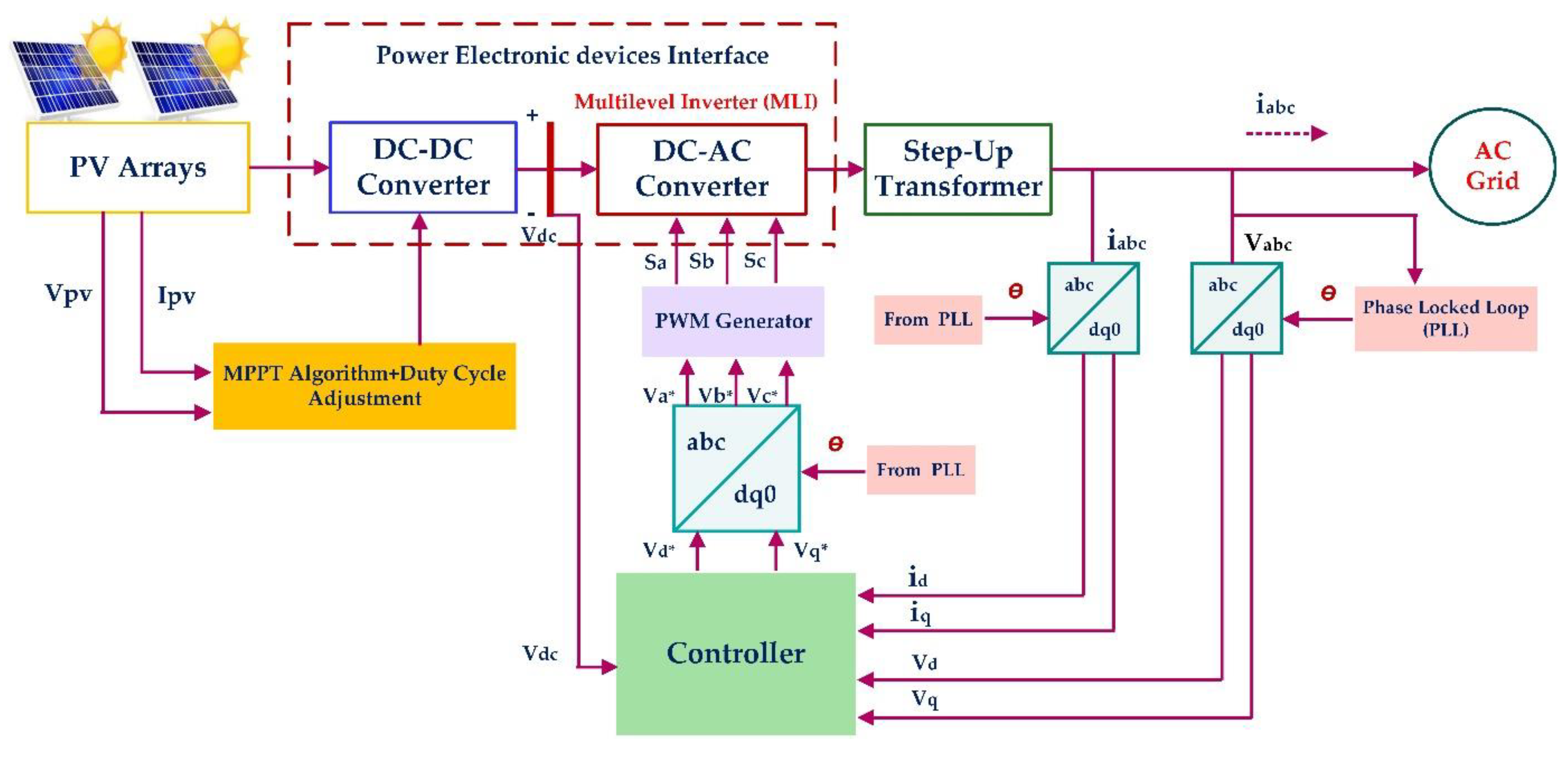
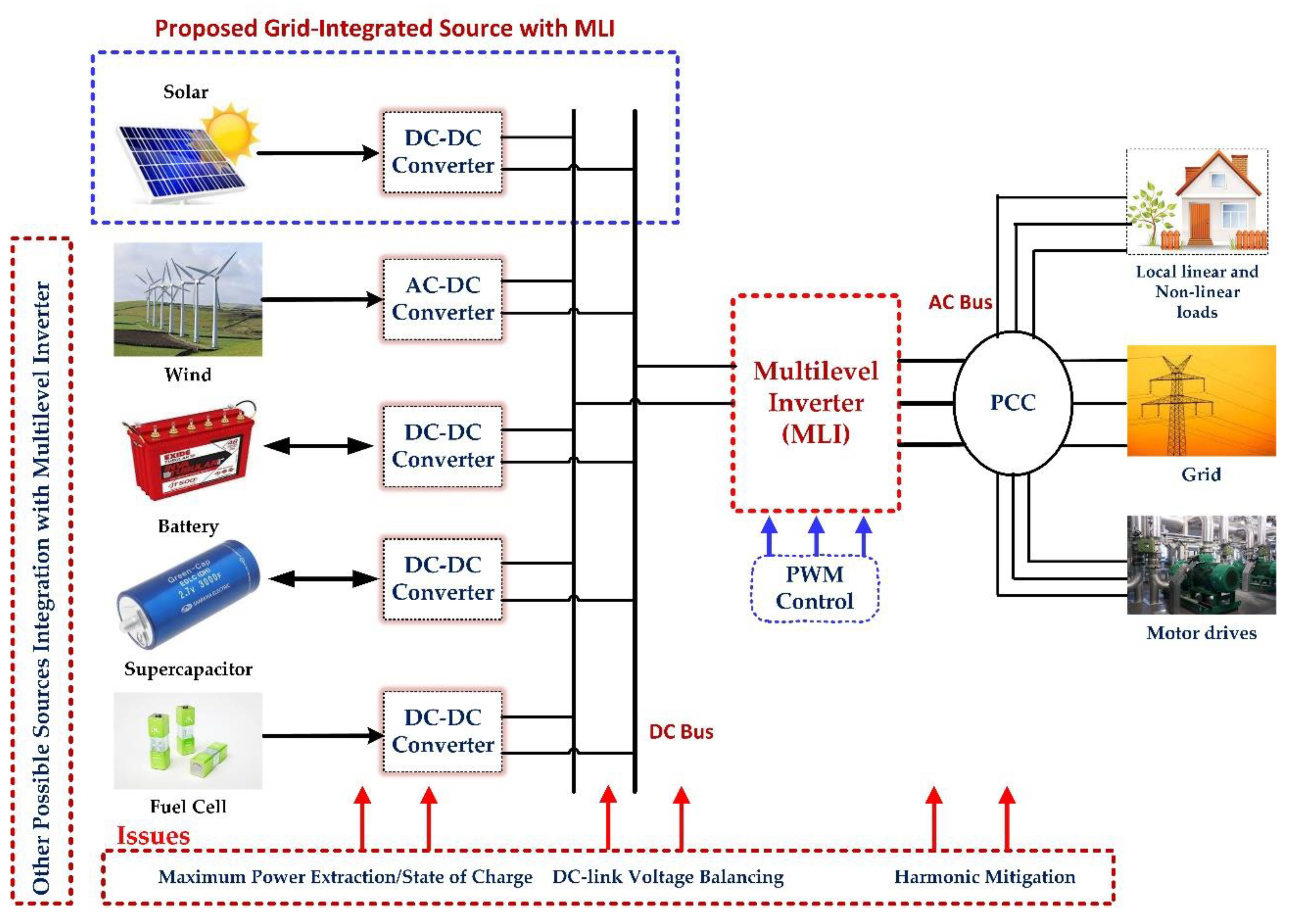
2. Grid-Connected Solar Photovoltaic System
- A.
- Reduced Switch Count Multilevel Inverters (RSC-MLIs): Background
- (i)
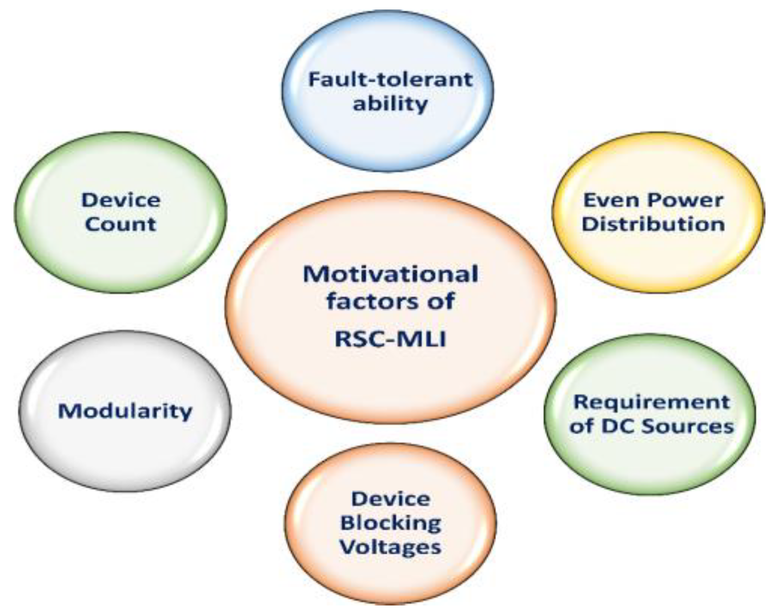
- Factors Contributing to Motivation
- (ii)
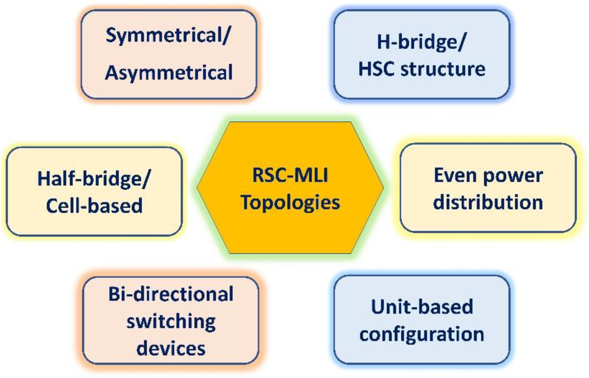
- Classification
- (iii)
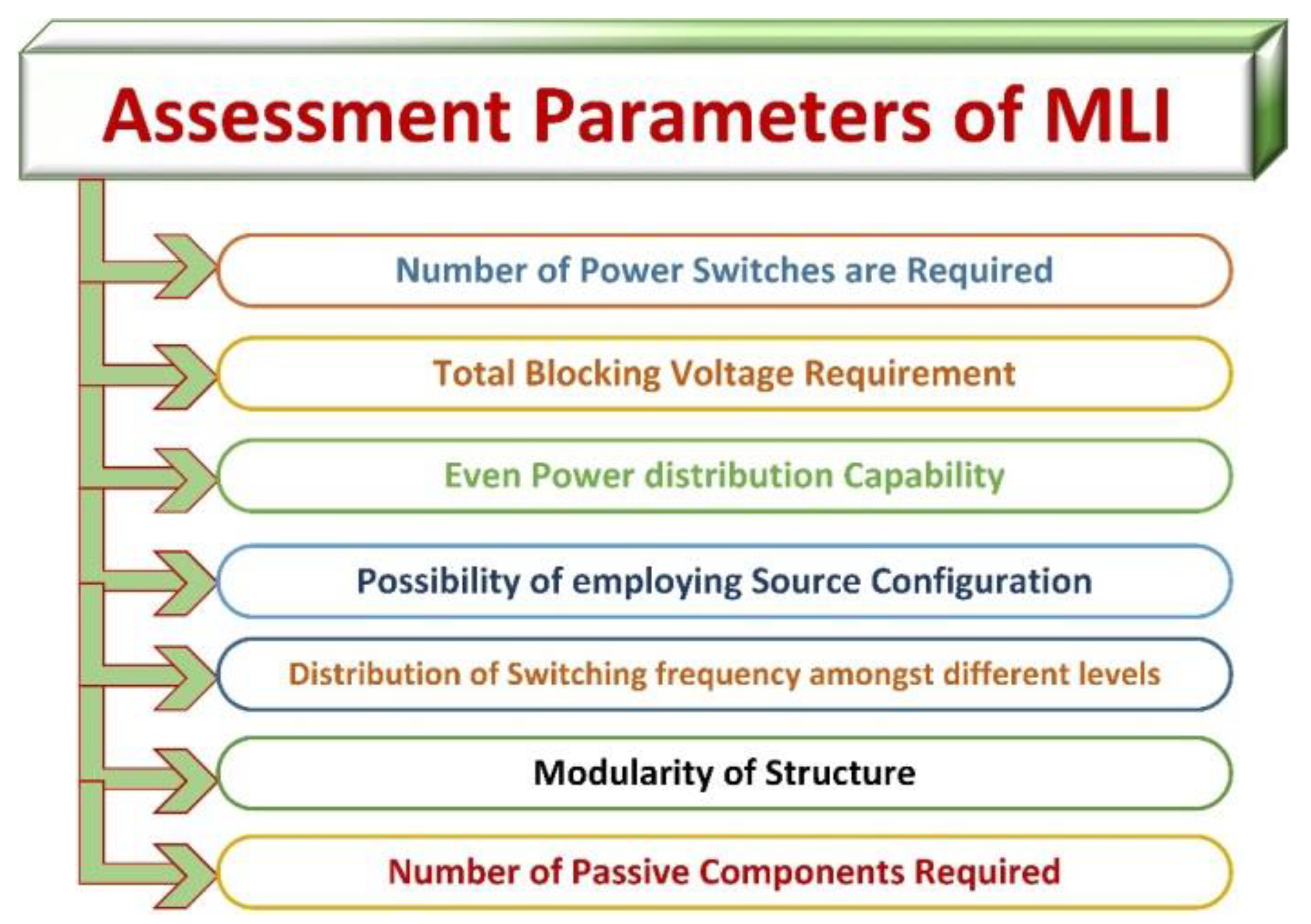
- The Evaluation Criteria for an MLI
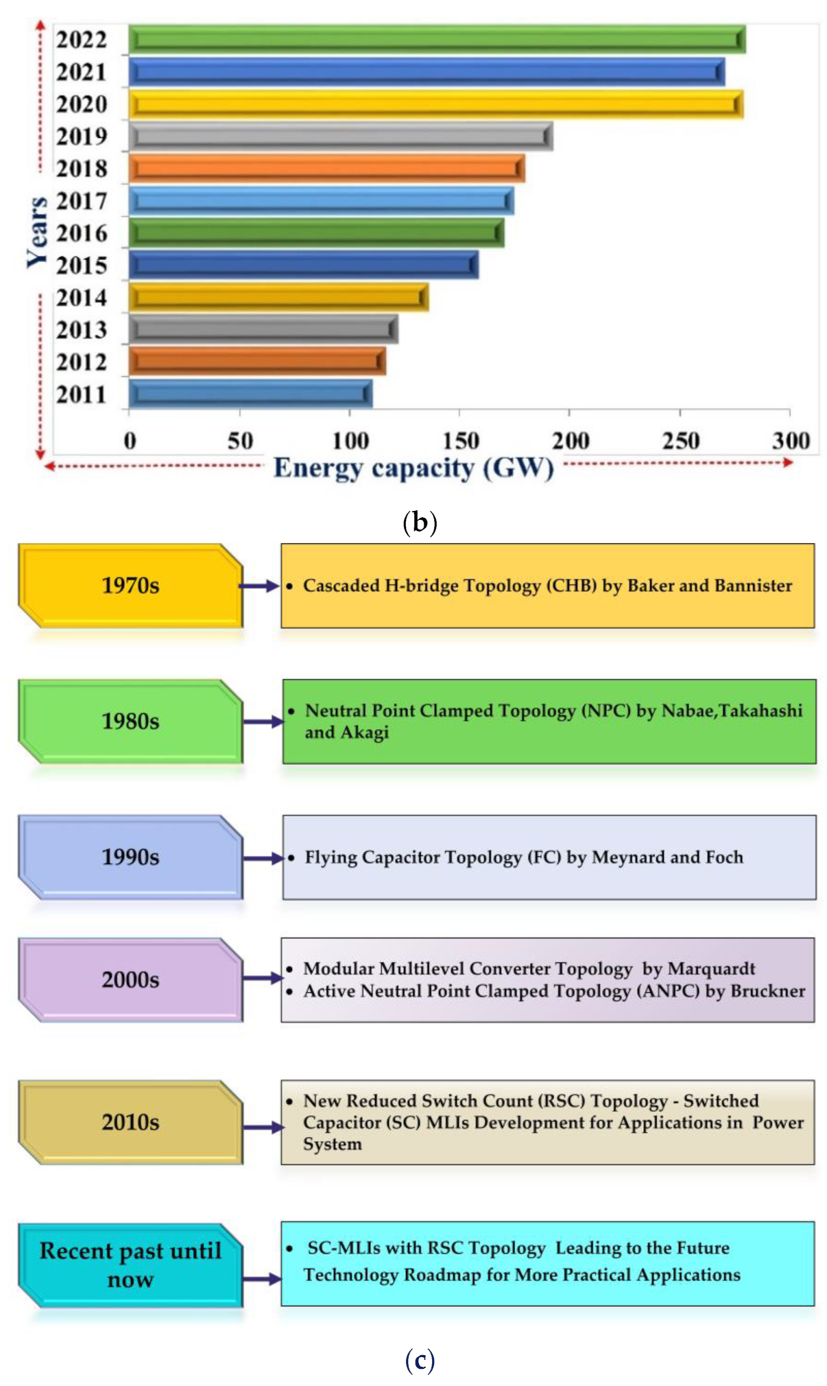
- Cascaded H-bridge multilevel inverter (CHB-MLI): This topology, which was initially patented by Baker and Bannister [1,39], was thought to be a good alternative to previously reported topologies since it required fewer power components. The series connection of H-bridges with independent DC sources makes up the topology known as the CHB-MLI. Many series-connected H-bridge constructions combine to produce the multilevel stepped waveform. A generic H-bridge cell can be cascaded to create the CHB-MLI that theoretically has an infinite number of layers. Due to its modular design, it effectively corrects the voltage imbalance that can be seen in NPC and FC settings. A CHB typically consists of power conversion cells connected in series on the AC side and individually powered by an isolated DC source from a battery, ultra-capacitor, or fuel cell on the DC side.
- Diode-clamped multilevel inverter (DC-MLI): Nabae, Takashi, and Akagi proposed the diode-clamped multilevel inverter (DC-MLI), also known as the NPC-MLI, in 1981 [73]. The widespread adoption of these inverters can be attributed to their tremendous competency in high-power and medium-voltage operations as well as their relatively high efficiency.
3. Reduced Switch Count Multilevel Inverters (RSC-MLIs) Topologies
- A.
- Generalized RSC-MLI Topologies
- (1)
- Separate Level and Polarity Generator Topologies
- (2)
- T-Type Structure Topologies
- (i)
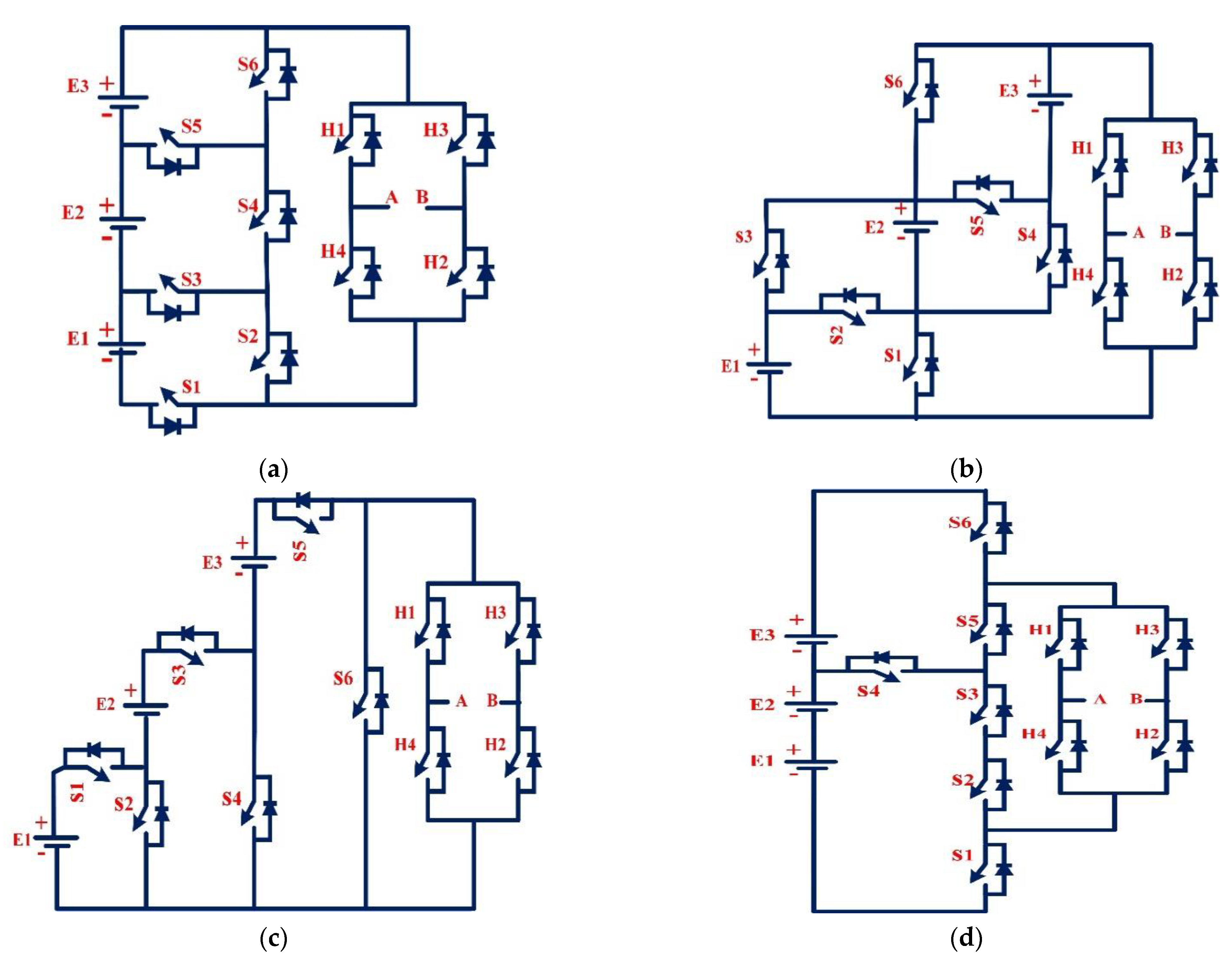
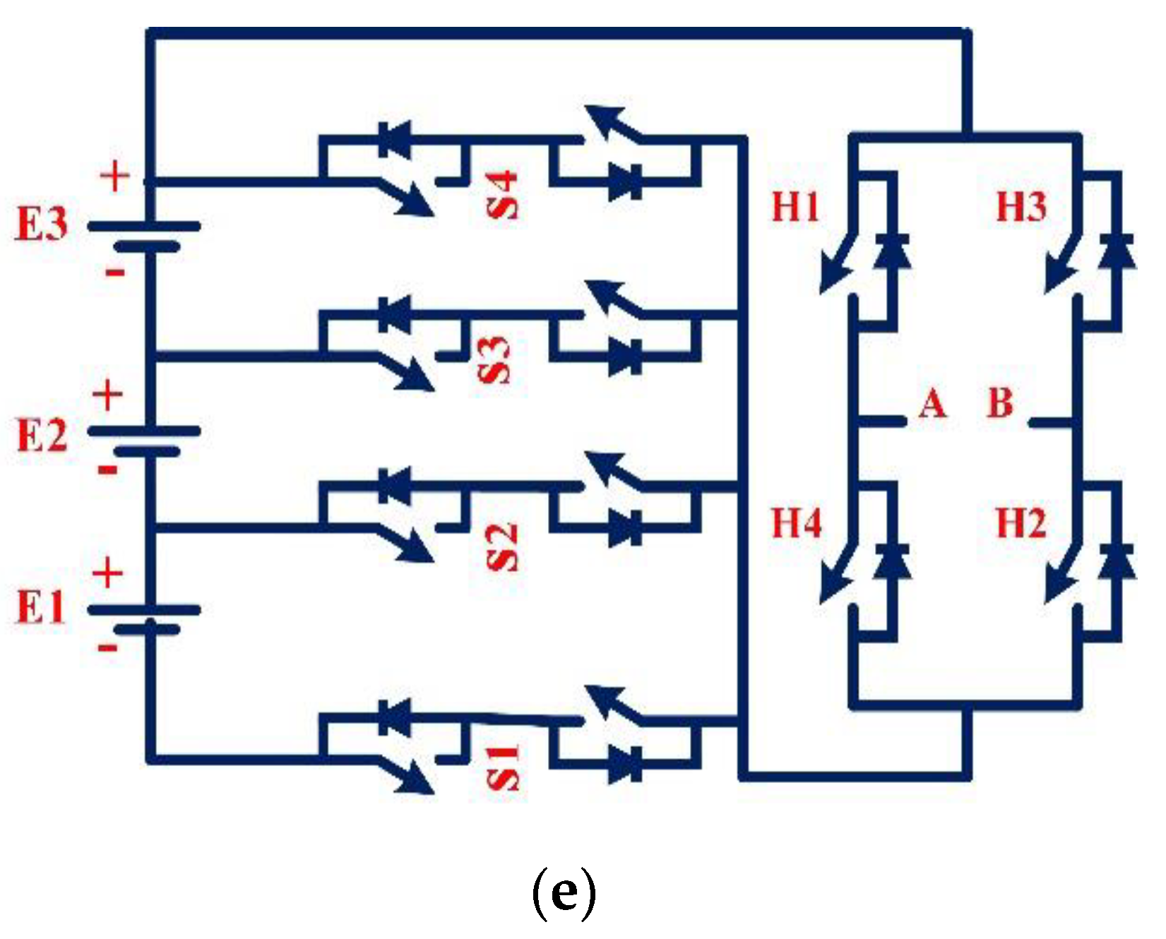
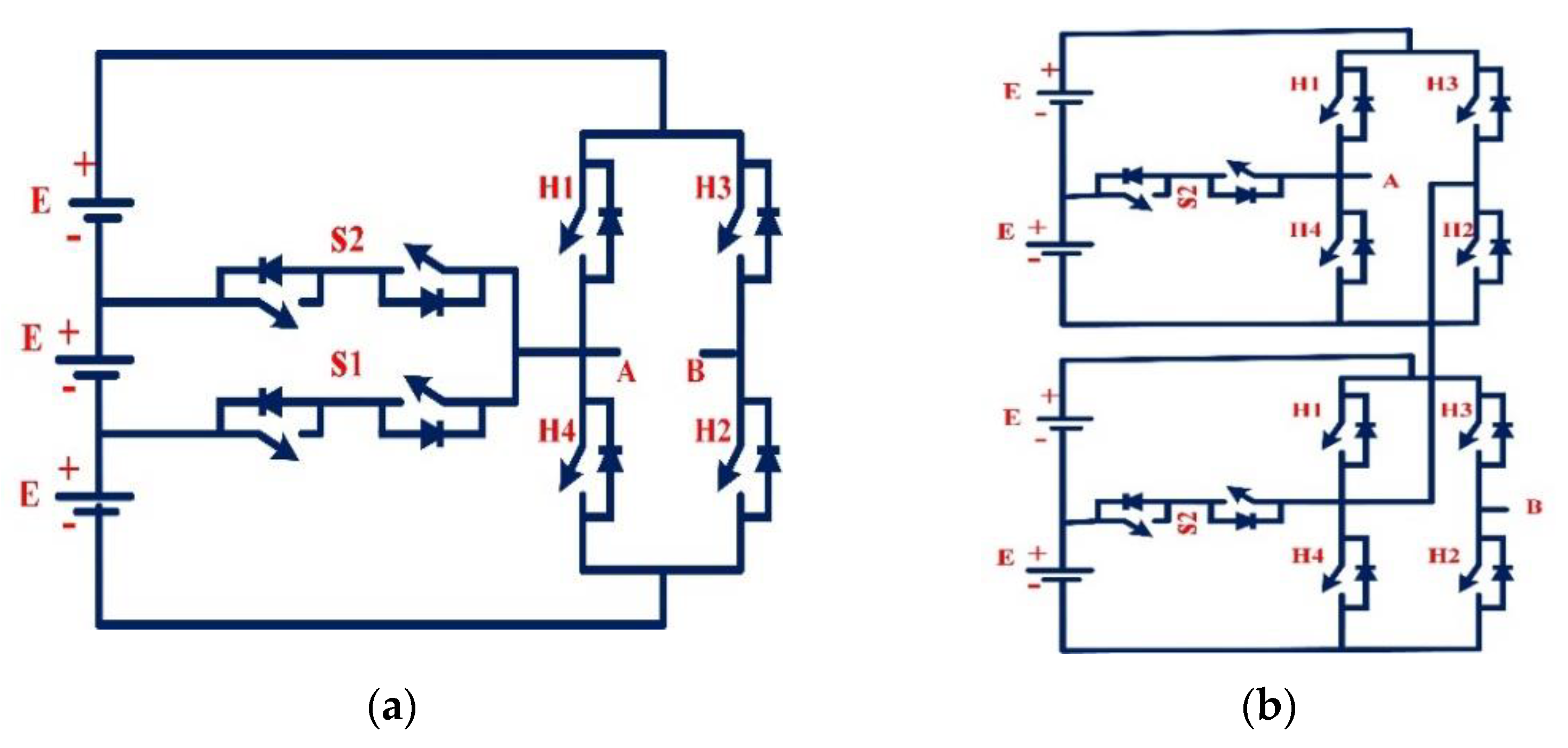
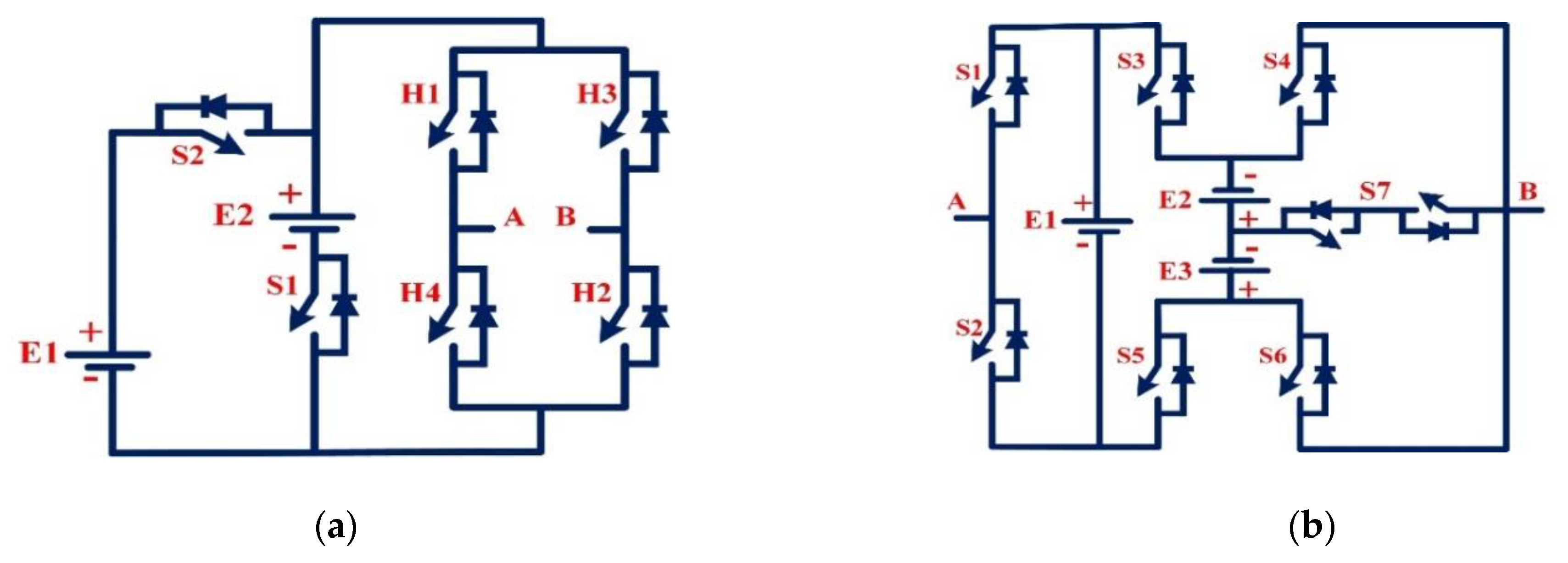
- T-type MLI: This type of architecture is based on H-bridges and was suggested by [2,133]. The H-bridge is built from the unidirectional switches, and the bidirectional switches connect the H-midpoint bridges to the DC-link voltages. Figure 12a depicts the T-type per-phase configuration with three DC voltage sources. With no redundancies, this topology is merely symmetrical. To increase the topology’s flexibility, the number of DC sources can be increased with bidirectional switches or cascade many T-type modules, which allows for uneven voltage ratios and switching redundancy. T-type modules should have the same DC-link voltage. A T-type MLI with two five-level T-type modules cascading is shown in Figure 12b.
- (ii)
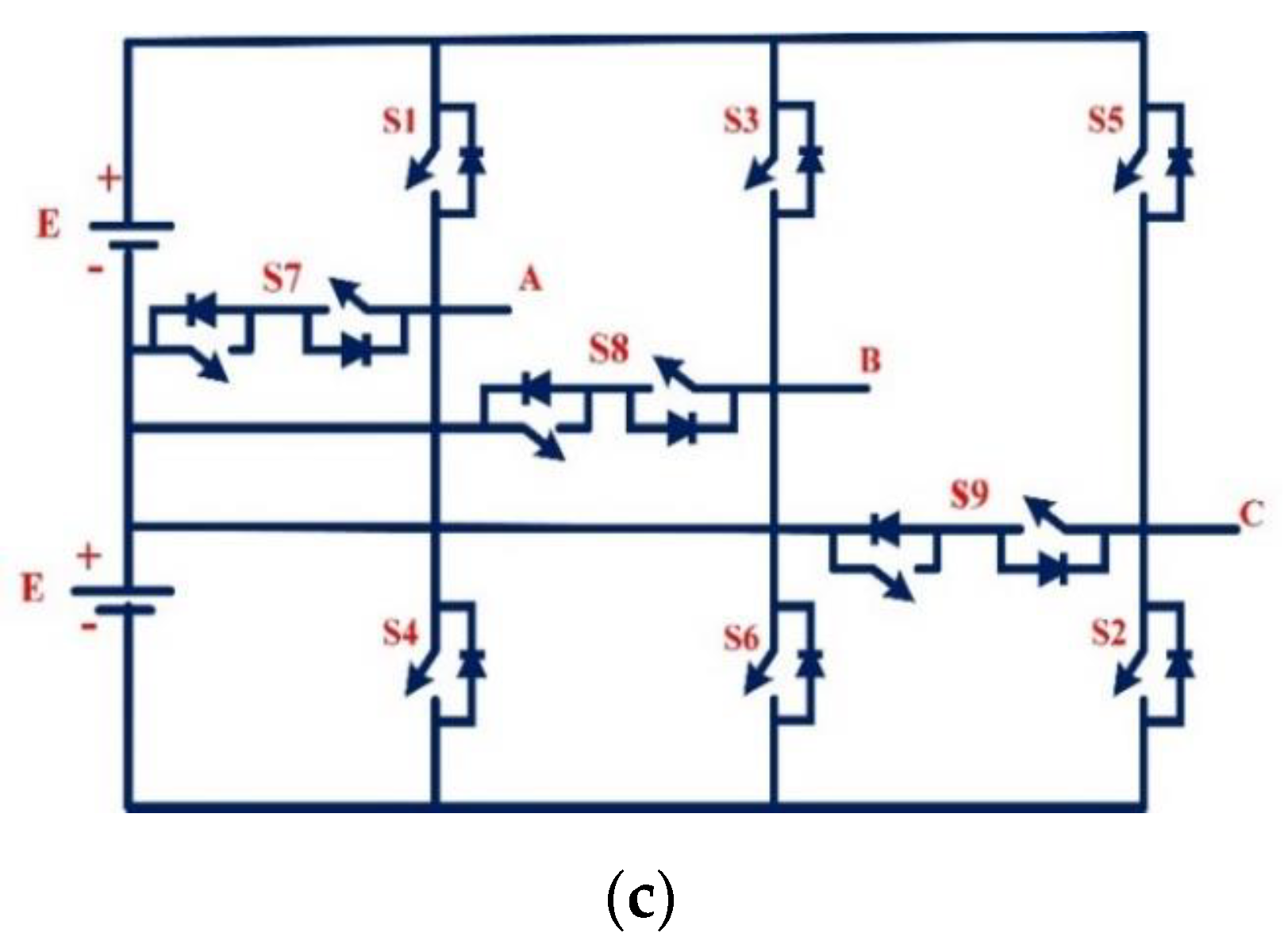
- Half-leg T-type MLI: Separately, the phase leg is linked to the DC link by bidirectional switches in half-bridge T-type topologies. A three-level topology is shown in Figure 12c as an example of this structure. To obtain larger levels, just increase the DC sources using bidirectional switches, which may provide even and odd phases of voltage. In Figure 12c, two devices per leg are in conduction at any one moment, and the voltage rating of bidirectional switches is smaller than the devices in a phase-leg. Due to minor conduction losses and a reduced total blocking voltage, this design is preferred over a DCMLI and ANPC in terms of efficiency. Many PV and grid-connected applications have used this design. When an open-circuit switch malfunction occurs, this inverter can be reconfigured to withstand the problem [2,132].
- (3)
- HSC Structure Topologies
- (i)
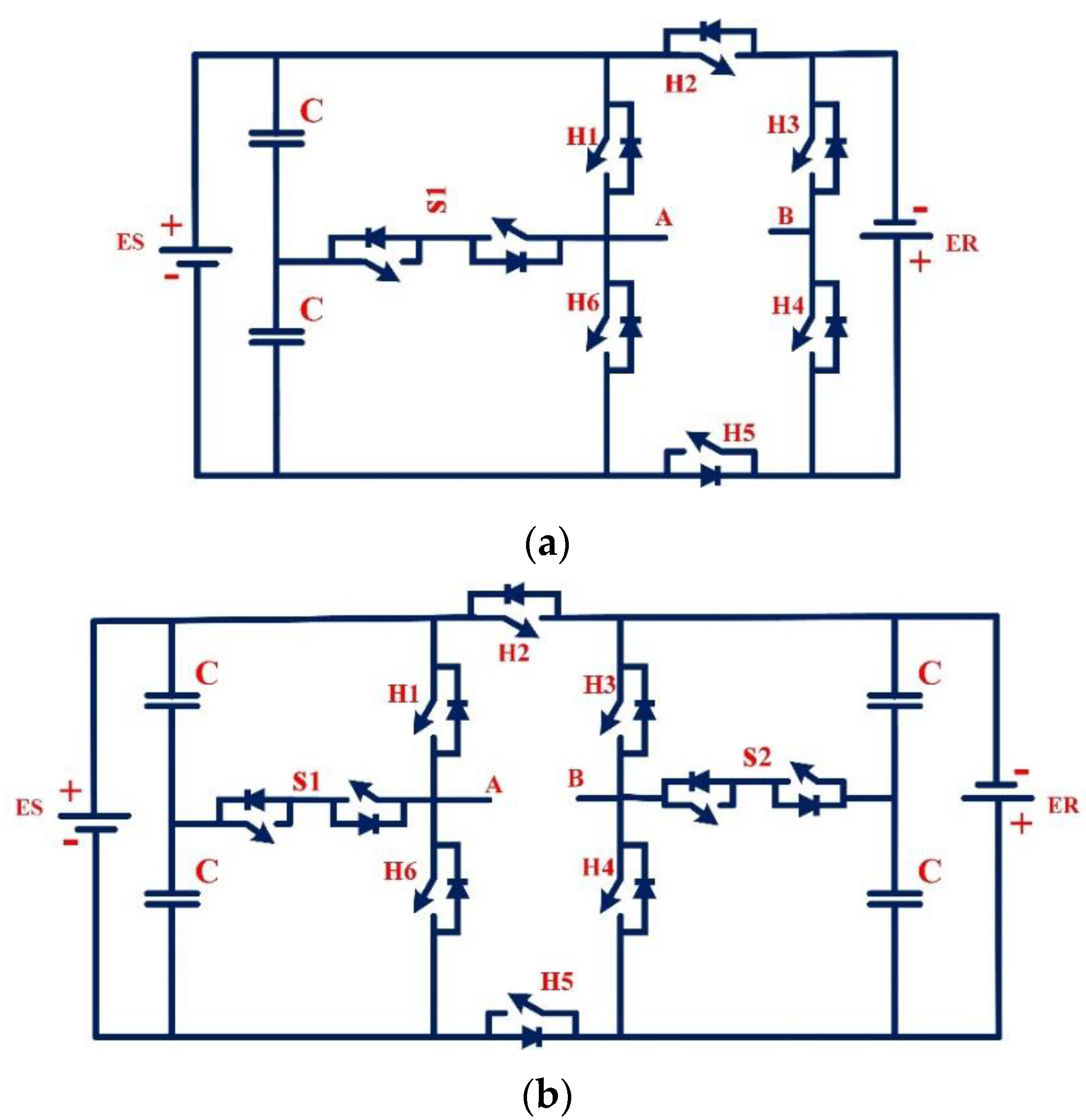
- Topology-I: A mix of T-type with HSC RSC-MLI topology with two stiff DC sources, i.e., ES and ER, on each side of the HSC. Figure 13a illustrates that more bidirectional switches or several modules cascaded together may expand this topology’s capabilities further. According to Figure 13a, this topology is similar to the five-level T-type MLI when short-circuiting and open-circuiting the unidirectional switches H5 and H2, as shown. Since there are now unidirectional switches, we can work in asymmetrical configurations with the H-bridge to HSC. Asymmetrical behavior occurs only when ES is less than or equal to the number of elements in the configuration. DC-link capacitors “n” in the asymmetrical design of this architecture can provide (4n + 1) levels of phase voltage. Other voltage levels can be operated by using an asymmetrical arrangement with suitable voltage ratios.
- (ii)
- B.
- Unit-Based RSC-MLIs
- (1)
- Basic Unit RSC-MLI Topology
- (2)
- Symmetrical Unit-Based Topology
- (i)
- Five-level configuration: To produce nine-level inverters, just cascade two units as indicated in Figure 15a. In each cycle, the cascaded units exchange switching pulses. Consequently, the units perform uniformly.
- (ii)
- Nine-level configuration: To compare, Topology-I of the hybrid T-type design seems to be comparable, with two DC-link capacitors of identical voltage, as illustrated in Figure 15b.
- (3)
- Asymmetrical Unit-Based Topologies
- a.
- Power loss efficiency calculations:
- b.
- Switch stress total standing voltage (TSV) calculations:
- c.
- Cost function (CF) parameter calculations:
- C.
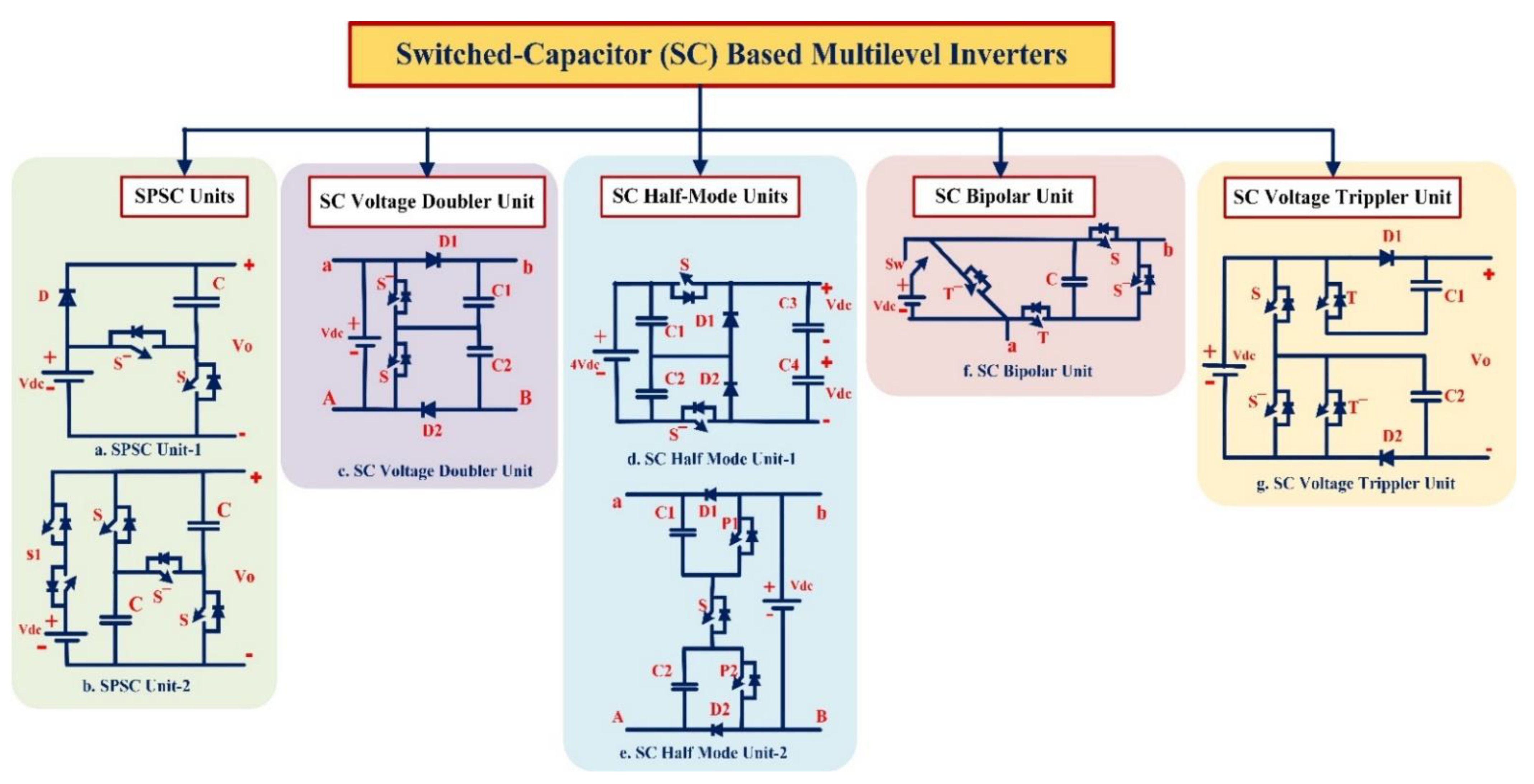
- Switched capacitor (SC) unit-based topologies
- Single DC-source SC-Unit-based MLIs
- SPSC Units
- b.
- SC Voltage Doubler Unit
- c.
- SC Half-Mode Units
- d.
- SC Bipolar Unit
- e.
- SC Voltage Tripler Units
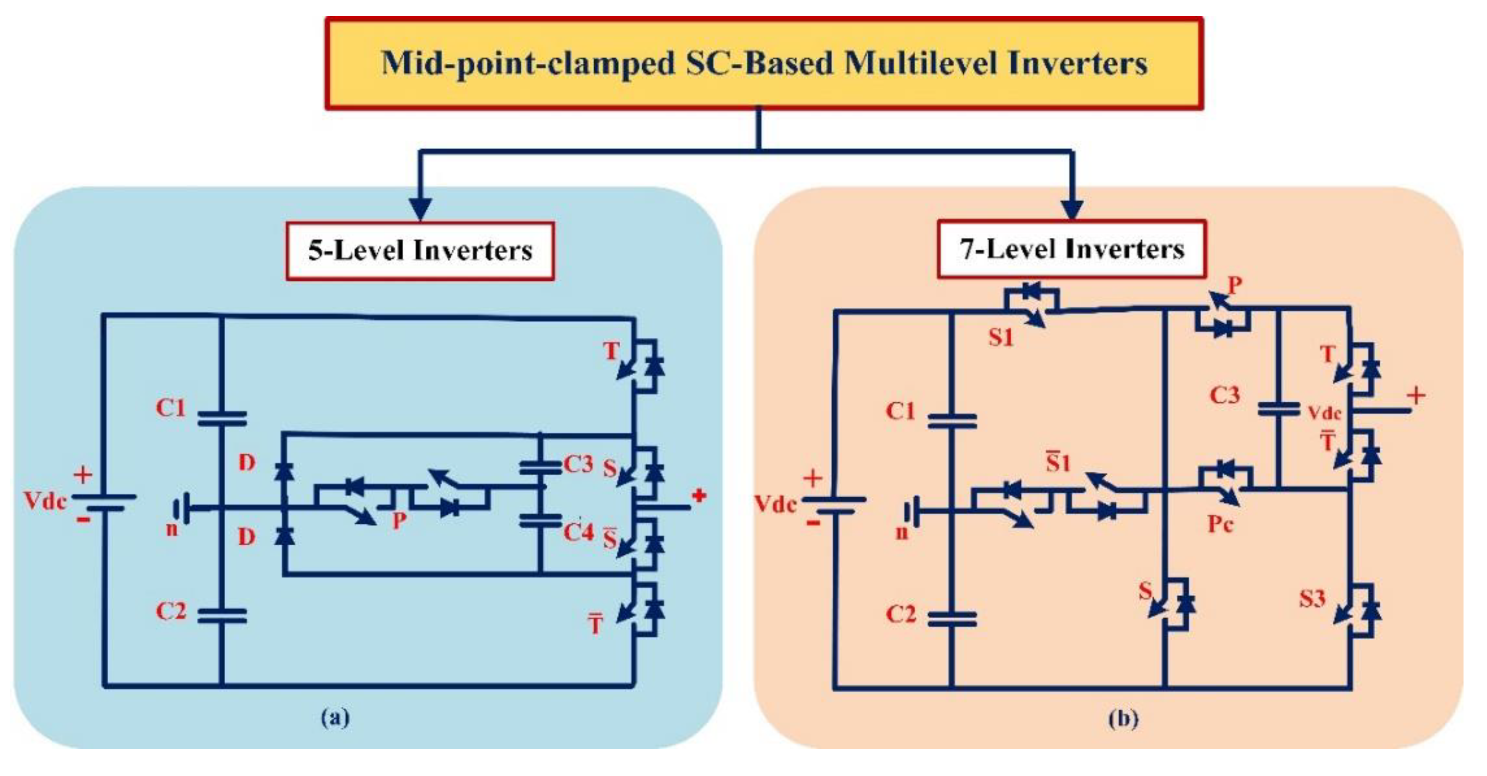
4. Mid-Point-Clamped SC-MLIs
- a.
- Five-Level mid-point-clamped SC-based inverter
- b.
- Seven-Level mid-point-clamped SC-based inverter
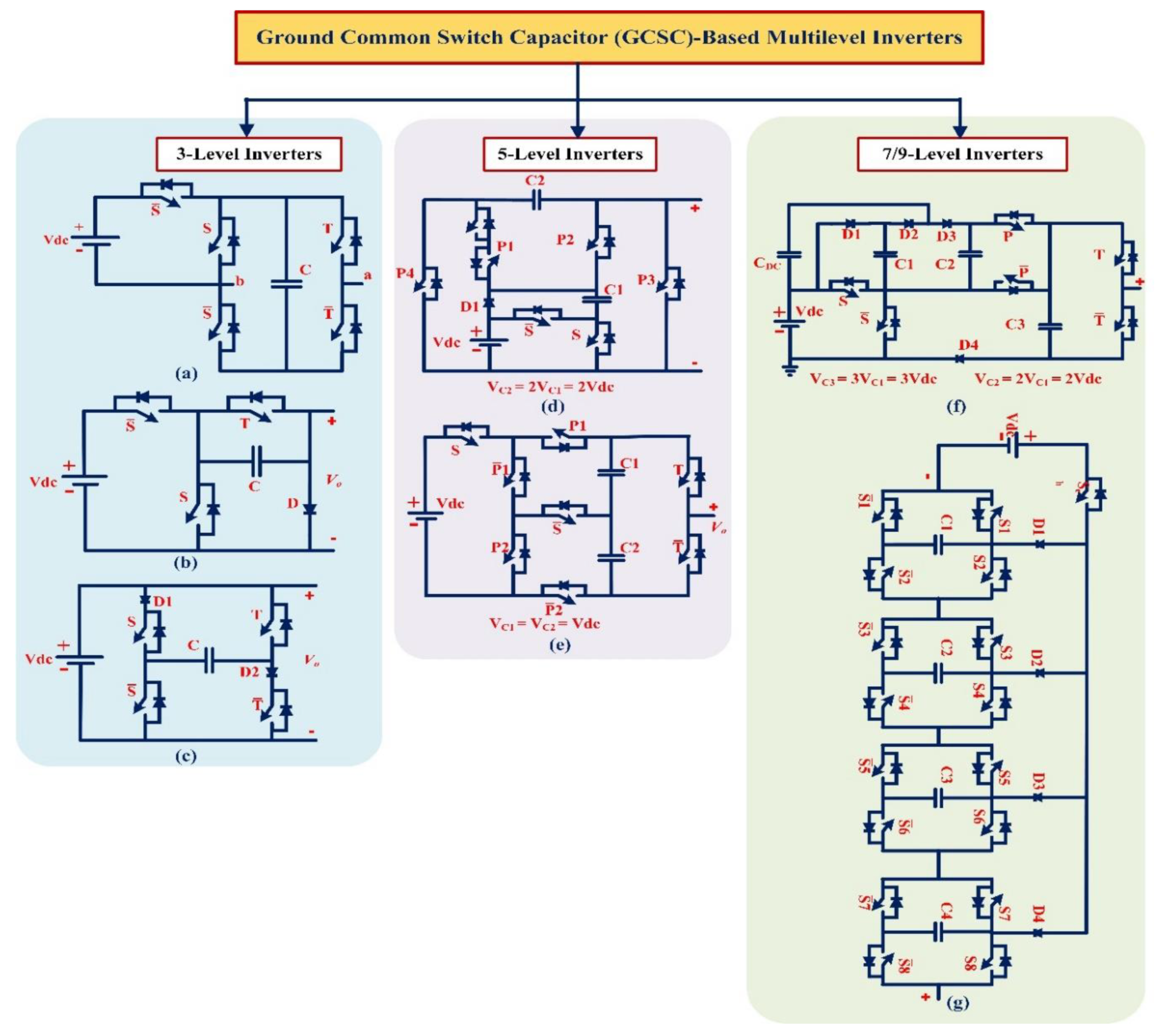
5. Common Ground Switched-Capacitor (CGSC)-Based MLIs
- a.
- Three-level CGSC-based inverter
- b.
- Five-level CGSC-based inverter
- c.
- Seven-level CGSC-based inverter
- d.
- Nine-Level CGSC-based inverter
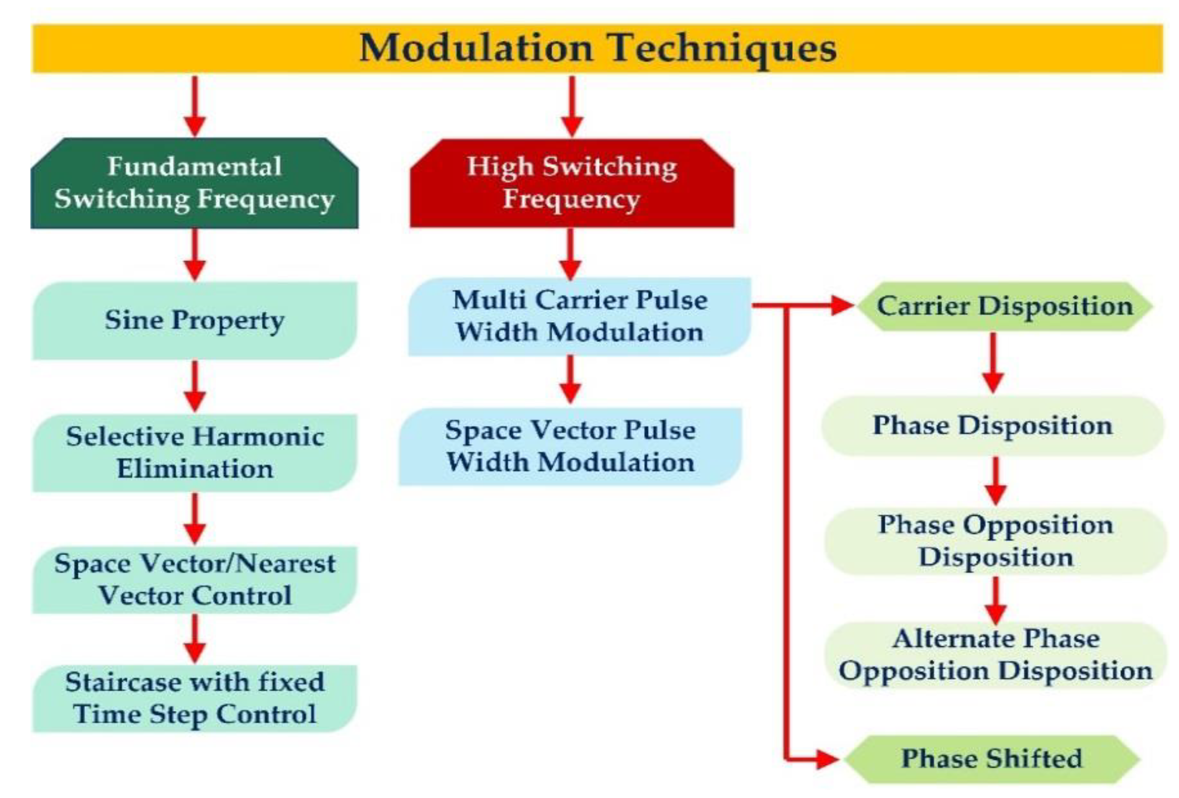
6. Modulation Techniques
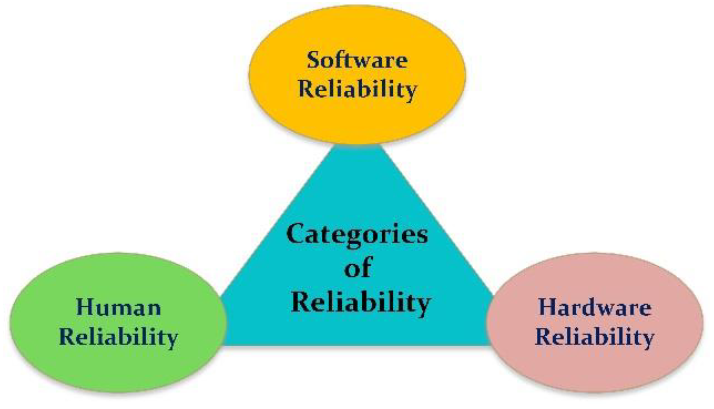
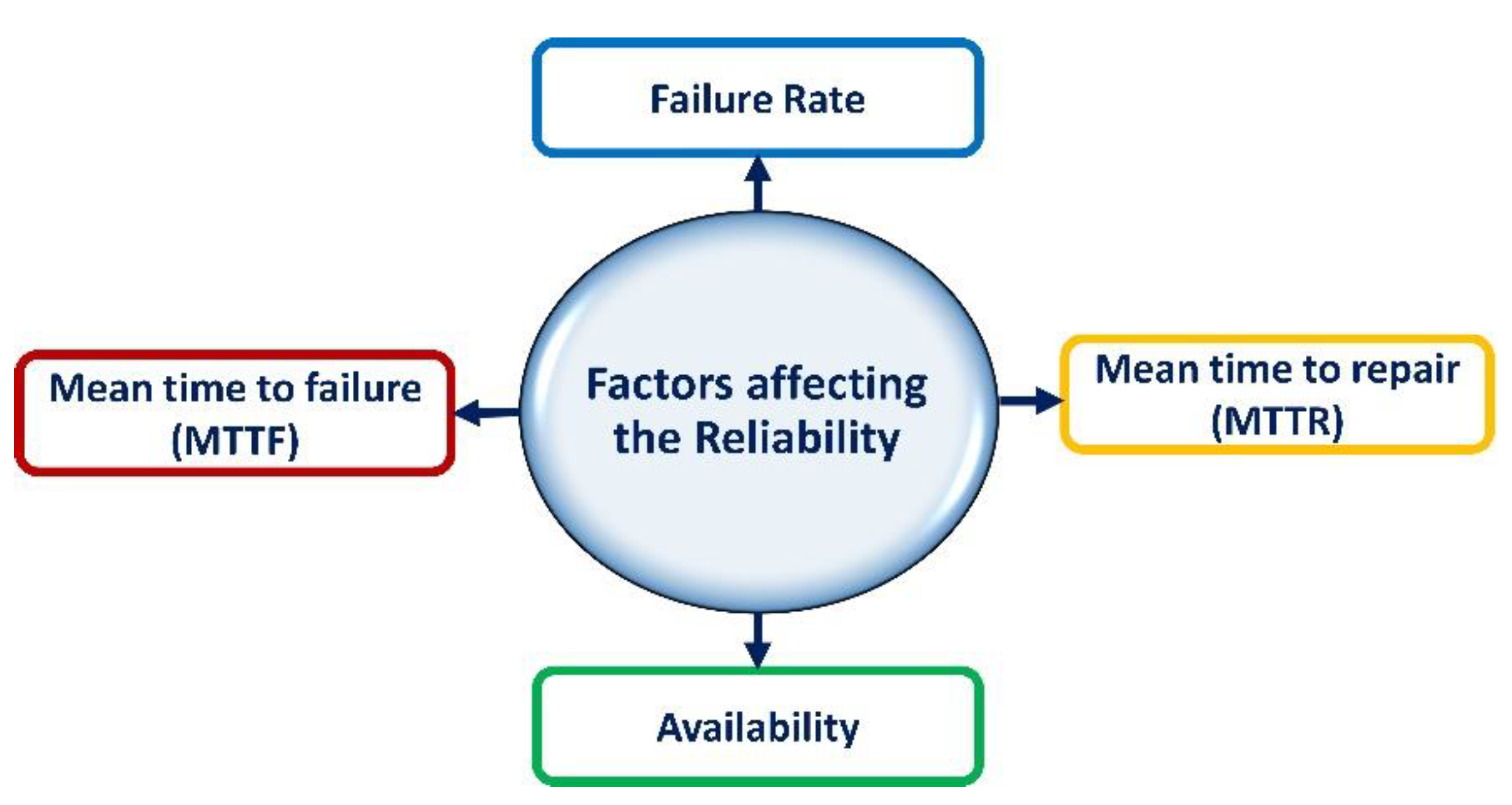
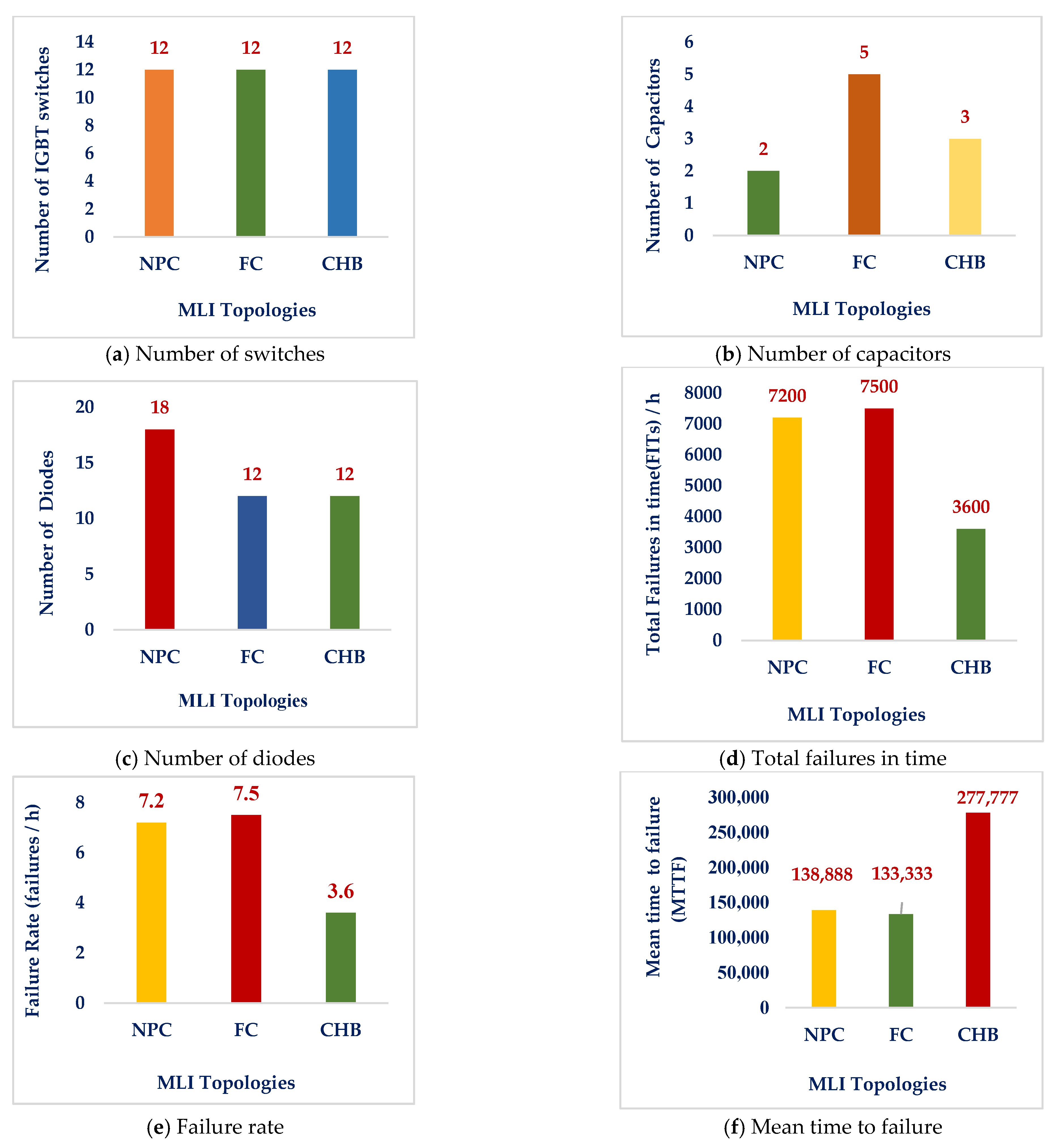
7. Reliability Assessment
- (a)
- Reliability
- (b)
- Failure
- (c)
- Failure Rate (FR)
- (d)
- Mean Time to Failure (MTTF)
- (e)
- Mean Time to Repair (MTTR)
- (f)
- Availability and Average Availability
8. Challenges and Recommendations
- The evaluation of the performance of these novel topologies in grid-integrated applications is imperative, as the majority of them have not yet been examined in the context of grid-connected Renewable Energy Sources (RESs).
- MLI control and modulation systems should be more robust, flexible, and fault tolerant.
- In recent times, researchers and industries have begun to develop hybrid topologies in order to successfully address power quality challenges and to meet demanding grid standards in a cost-efficient manner.
- More research is needed on quantitative approaches for solving MLI nonlinear systems.
- New voltage balancing techniques must be employed in MLIs to minimize capacitor size and to increase inverter power density.
- Resonant converters with single DC source MLIs are suggested.
- It is imperative for smart grid systems to include the integration of microgrid load interactions with MLIs as an essential component.
- However, because of the lower TSV, new RSC-MLI topologies need to be created to boost their appropriateness for both solar PV and wind energy integration.
- Renewable energy sources are increasingly evolving towards a future smart grid as they are integrated into networks utilizing appropriate MLIs, and for MLI topology creation and control, this poses considerable hurdles. There have been many breakthroughs in this sector.
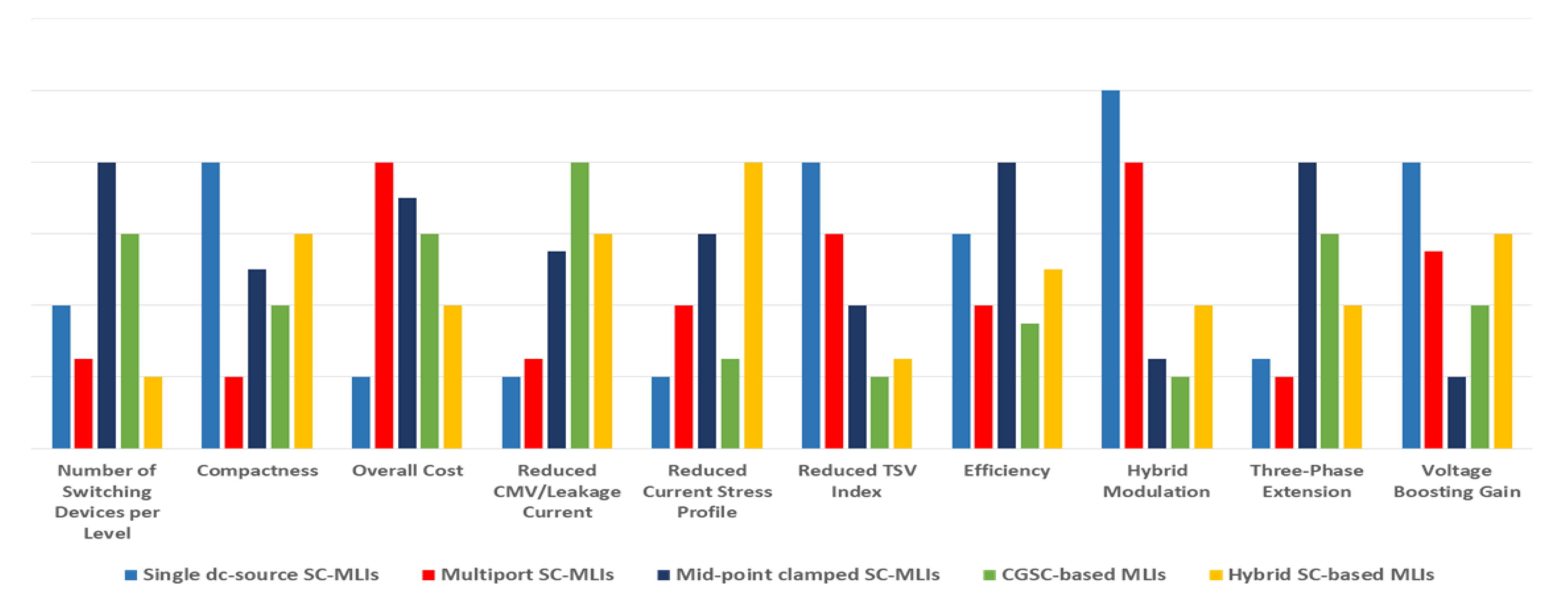
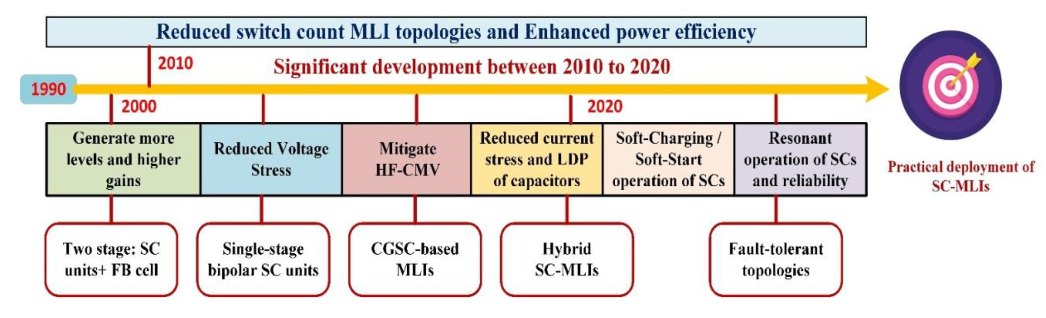
- The roadmap in Figure 31 shows SC-MLIs’ future progress. In addition to exploring new topologies with higher voltage conversion gain, future SC-MLIs can consider factors such as fewer switching devices, reduced MVS and TSV index across switches, improved performance during high pulsating inrush current, and lower cost.
- In grid-connected solar PV systems, safe and reliable operation of the multilevel inverter depends on the use of suitable safety mechanisms and control strategies, which are listed in Table 16.
9. Conclusions
Author Contributions
Funding
Data Availability Statement
Acknowledgments
Conflicts of Interest
Abbreviations
| MLIs | Multilevel inverters |
| RES | Renewable energy sources |
| NPC | Neutral point clamped |
| SC-MLI | Switched-capacitor multilevel inverters |
| DC-MLI | Diode-clamped multilevel inverters |
| DCC | Developed cascaded cell based |
| PUC | Packed U-cell |
| NSWT | Number of switches |
| NDCS | Number of DC sources |
| NL | Number of levels |
| NDIO | Number of diodes |
| NCAP | Number of capacitors |
| NDK | Number of driver circuits |
| TSVPU | Total standing voltage per unit |
| CF/L | Cost function |
| FCC/L | Component count factor per level |
| CHB-MLI | Cascaded H-bridge multilevel inverter |
| PV | Photovoltaic |
| SDCS | Separate DC source |
| MPPT | Maximum power point tracking |
| THD | Total harmonic distortion |
| EMI | Electromagnetic interference |
| MMC | Modular multilevel converter |
| FC-MLI | Flying-capacitor multilevel inverter |
| CSD | Cascaded switched diode |
| CPCC | Cascaded predictive current control |
| CCHB | Cross-connected half-bridges |
| CCS | Cross-connected source based |
| MCSI | Multilevel current-source inverter |
| ASD | Adjustable speed drives |
| AFC | Active front-end converters |
| CPD | Custom power devices |
| ANPC | Active neutral point clamped |
| ABNPC | Active boost neutral point clamped |
| PWM | Pulse width modulation |
| CGSC | Common-grounded switched-capacitor |
| FACTS | Flexible alternating current transmission systems |
| MLDCL | Multilevel DC-link |
| SSPS | Switched series-parallel sources |
| SPSC | Series–parallel switched-capacitor |
| SSSC | Single-source switched-capacitor |
| SADC | Symmetric–asymmetric DC sources based |
| RV | Reverse voltage |
| RVDC-C | Reduced variety of DC voltage sources based cascaded |
| HERC-C | Highly efficient and reliable configuration based cascaded |
| SCSS | Series-connected switched sources |
| SCU | Switched-capacitor Unit |
| MLM | Multilevel module |
| HBSC | Half-bridge switched-capacitor |
| SCC | Switched-capacitor converters |
References
- Choudhury, S.; Bajaj, M.; Dash, T.; Kamel, S.; Jurado, F. Multilevel Inverter: A Survey on Classical and Advanced Topologies, Control Schemes, Applications to Power System and Future Prospects. Energies 2021, 14, 5773. [Google Scholar] [CrossRef]
- Vemuganti, H.P.; Sreenivasarao, D.; Ganjikunta, S.K.; Suryawanshi, H.M.; Abu-Rub, H. A Survey on Reduced Switch Count Multilevel Inverters. IEEE Open J. Ind. Electron. Soc. 2021, 2, 80–111. [Google Scholar] [CrossRef]
- Dhanamjayulu, C.; Prasad, D.; Padmanaban, S.; Maroti, P.K.; Holm-Nielsen, J.B.; Blaabjerg, F. Design and Implementation of Seventeen Level Inverter With Reduced Components. IEEE Access 2021, 9, 16746–16760. [Google Scholar] [CrossRef]
- Dhanamjayulu, C.; Padmanaban, S.; Holm-Nielsen, J.B.; Blaabjerg, F. Design and Implementation of a Single-Phase 15-Level Inverter with Reduced Components for Solar PV Applications. IEEE Access 2021, 9, 581–594. [Google Scholar] [CrossRef]
- Khasim, S.R.; Dhanamjayulu, C.; Padmanaban, S.; Holm-Nielsen, J.B.; Mitolo, M. A Novel Asymmetrical 21-Level Inverter for Solar PV Energy System with Reduced Switch Count. IEEE Access 2021, 9, 11761–11775. [Google Scholar] [CrossRef]
- Dhanamjayulu, C.; Rudravaram, V.; Sanjeevikumar, P. Design and implementation of a novel 35-level inverter topology with reduced switch count. Electr. Power Syst. Res. 2022, 212, 108641. [Google Scholar] [CrossRef]
- Khasim, S.R.; Dhanamjayulu, C. Design and Implementation of Asymmetrical Multilevel Inverter with Reduced Components and Low Voltage Stress. IEEE Access 2022, 10, 3495–3511. [Google Scholar] [CrossRef]
- Roy, T.; Sadhu, P.K.; Dasgupta, A. Cross-switched multilevel inverter using novel switched capacitor converters. IEEE Trans. Ind. Electron. 2019, 66, 8521–8532. [Google Scholar] [CrossRef]
- Gupta, K.K.; Ranjan, A.; Bhatnagar, P.; Sahu, L.K.; Jain, S. Multilevel inverter topologies with reduced device count: A review. IEEE Trans. Power Electron. 2016, 31, 135–151. [Google Scholar] [CrossRef]
- Samanbakhsh, R.; Taheri, A. Reduction of power electronic components in multilevel converters using new switched capacitor-diode structure. IEEE Trans. Ind. Electron. 2016, 63, 7204–7214. [Google Scholar] [CrossRef]
- Barzegarkhoo, R.; Zamiri, E.; Vosoughi, N.; Kojabadi, H.M.; Chang, L. Cascaded multilevel inverter using series connection of novel capacitor based units with minimum switch count. IET Power Electron. 2016, 9, 2060–2075. [Google Scholar] [CrossRef]
- Tayyab, M.; Sarwar, A.; Tariq, M.; Chakrabortty, R.K.; Ryan, M.J. Hardware-in-the-loop implementation of projectile target search algorithm for selective harmonic elimination in a 3-phase multilevel converter. IEEE Access 2021, 9, 30626–30635. [Google Scholar] [CrossRef]
- Iqbal, A.; Siddique, M.D.; Reddy, B.P.; Maroti, P.K. Quadruple boost multilevel inverter (QB-MLI) topology with reduced switch count. IEEE Trans. Power Electron. 2021, 36, 7372–7377. [Google Scholar] [CrossRef]
- Reddy, B.P.; Siddique, M.D.; Iqbal, A.; Mekhilef, S.; Rahman, S.; Maroti, P.K. 7L-SCBI topology with minimal semiconductor device count. IET Power Electron. 2020, 13, 3199–3203. [Google Scholar] [CrossRef]
- Barzegarkhoo, R.; Kojabadi, H.M.; Zamiry, E.; Vosoughi, N.; Chang, L. Generalized structure for a single phase switched-capacitor multilevel inverter using a new multiple DC link producer with reduced number of switches. IEEE Trans. Power Electron. 2016, 31, 5604–5617. [Google Scholar] [CrossRef]
- Siddique, M.D.; Karim, M.F.; Mekhilef, S.; Rawa, M.; Seyedmahmoudian, M.; Horan, B.; Stojcevski, A.; Ahmed, M. Single-Phase Boost Switched-Capacitor-Based Multilevel Inverter Topology With Reduced Switching Devices. IEEE J. Emerg. Sel. Top. Power Electron. 2022, 10, 4336–4346. [Google Scholar] [CrossRef]
- Siddique, M.D.; Mekhilef, S.; Shah, N.M.; Sarwar, A.; Iqbal, A.; Memon, M.A. A New Multilevel Inverter Topology With Reduce Switch Count. IEEE Access 2019, 7, 58584–58594. [Google Scholar] [CrossRef]
- Siddique, M.D.; Iqbal, A.; Memon, M.A.; Mekhilef, S. A New Configurable Topology for Multilevel Inverter With Reduced Switching Components. IEEE Access 2020, 8, 188726–188741. [Google Scholar] [CrossRef]
- Siddique, M.D.; Mekhilef, S.; Rawa, M.; Wahyudie, A.; Chokaev, B.; Salamov, I. Extended Multilevel Inverter Topology With Reduced Switch Count and Voltage Stress. IEEE Access 2020, 8, 201835–201846. [Google Scholar] [CrossRef]
- Panda, K.P.; Bana, P.R.; Panda, G. FPA Optimized Selective Harmonic Elimination in Symmetric–Asymmetric Reduced Switch Cascaded Multilevel Inverter. IEEE Trans. Ind. Appl. 2020, 56, 2862–2870. [Google Scholar] [CrossRef]
- Ali, J.S.M.; Almakhles, D.J.; Ibrahim, S.A.A.; Alyami, S.; Selvam, S.; Bhaskar, M.S. A Generalized Multilevel Inverter Topology With Reduction of Total Standing Voltage. IEEE Access 2020, 8, 168941–168950. [Google Scholar] [CrossRef]
- Siddique, M.D.; Mekhilef, S.; Shah, N.M.; Memon, M.A. Optimal Design of a New Cascaded Multilevel Inverter Topology With Reduced Switch Count. IEEE Access 2019, 7, 24498–24510. [Google Scholar] [CrossRef]
- Koohi-Fayegh, S.; Rosen, M.A. A review of energy storage types, applications and recent developments. J. Energy Storage 2020, 27, 101047. [Google Scholar] [CrossRef]
- Vijeh, M.; Rezanejad, M.; Samadaei, E.; Bertilsson, K. A general review of multilevel inverters based on main submodules: Structural point of view. IEEE Trans. Power Electron. 2019, 34, 9479–9502. [Google Scholar] [CrossRef]
- Bana, P.R.; Panda, K.P.; Naayagi, R.; Siano, P.; Panda, G. Recently developed reduced switch multilevel inverter for renewable energy integration and drives application: Topologies, comprehensive analysis and comparative evaluation. IEEE Access 2019, 7, 54888–54909. [Google Scholar] [CrossRef]
- Kumari, M.; Siddique, M.D.; Sarwar, A.; Tariq, M.; Mekhilef, S.; Iqbal, A. Recent trends and review on switched-capacitor-based single stage boost multilevel inverter. Int. Trans. Elect. Energy Syst. 2021, 31, e12730. [Google Scholar] [CrossRef]
- Khan, M.N.H.; Forouzesh, M.; Siwakoti, Y.P.; Li, L.; Blaabjerg, F. Switched capacitor integrated (2n+1)-level step-up single-phase inverter. IEEE Trans. Power Electron. 2020, 35, 8248–8260. [Google Scholar] [CrossRef]
- Nakagawa, Y.; Koizumi, H. A boost-type nine-level switched capacitor inverter. IEEE Trans. Power Electron. 2019, 34, 6522–6532. [Google Scholar] [CrossRef]
- Barzegarkhoo, R.; Siwakoti, Y.P.; Aguilera, R.P.; Khan, M.N.H.; Lee, S.S.; Blaabjerg, F. A novel dual-mode switched-capacitor five-level inverter with common-ground transformerless concept. IEEE Trans. Power Electron. 2021, 36, 13740–13753. [Google Scholar] [CrossRef]
- Khan, M.N.H.; Siwakoti, Y.P.; Scott, M.J.; Li, L.; Khan, S.A.; Lu, D.D.C.; Barzegarkhoo, R.; Sidorski, F.; Blaabjerg, F.; Hasan, S.U. A common grounded type dual-mode five-level transformerless inverter for photovoltaic applications. IEEE Trans. Ind. Electron. 2021, 68, 9742–9754. [Google Scholar] [CrossRef]
- Ye, Y.; Chen, S.; Zhang, X.; Yi, Y. Half-bridge modular switched capacitor multilevel inverter with hybrid pulsewidth modulation. IEEE Trans. Power Electron. 2020, 35, 8237–8247. [Google Scholar] [CrossRef]
- Saeedian, M.; Adabi, M.E.; Hosseini, S.M.; Adabi, J.; Pouresmaeil, E. A novel step-up single source multilevel inverter: Topology, operating principle, and modulation. IEEE Trans. Power Electron. 2019, 34, 3269–3282. [Google Scholar] [CrossRef]
- Saeedian, M.; Adabi, M.E.; Adabi, J. Step-up switched-capacitor module for cascaded MLI topologies. IET Power Electron. 2018, 11, 1286–1296. [Google Scholar] [CrossRef]
- Jahan, H.K. A new transformerless inverter with leakage current limiting and voltage boosting capabilities for grid-connected PV applications. IEEE Trans. Ind. Electron. 2020, 67, 10542–10551. [Google Scholar] [CrossRef]
- Ye, Y.; Chen, S.; Hua, T.; Lin, M.; Wang, X. Self-balanced multilevel inverter with hybrid double- and half-mode switched capacitor. IEEE Trans. Ind. Electron. 2022, 69, 5735–5744. [Google Scholar] [CrossRef]
- Sarwer, Z.; Siddique, M.D.; Sarwar, A.; Zaid, M.; Iqbal, A.; Mekhilef, S. A switched-capacitor multilevel inverter topology employing a novel variable structure nearest-level modulation. Int. Trans. Elect. Energy Syst. 2021, 31, e13151. [Google Scholar] [CrossRef]
- Anand, V.; Singh, V. A 13-level switched-capacitor multilevel inverter with single dc source. IEEE J. Emerg. Sel. Topics Power Electron. 2022, 10, 1575–1586. [Google Scholar] [CrossRef]
- Roy, T.; Tesfay, M.W.; Nayak, B.; Panigrahi, C.K. A 7-level switched capacitor multilevel inverter with reduced switches and voltage stresses. IEEE Trans. Circuits Syst. II Exp. Briefs 2021, 68, 3587–3591. [Google Scholar] [CrossRef]
- Sharma, P.; Naidu, R.C. Optimization techniques for grid-connected PV with retired EV batteries in centralized charging station with challenges and future possibilities: A review. Ain Shams Eng. J. 2023, 14, 101985. [Google Scholar] [CrossRef]
- Barzegarkhoo, R.; Zamiri, E.; Moradzadeh, M.; Shadabi, H. Symmetric hybridised design for a novel step-up 19-level inverter. IET Power Electron. 2017, 10, 1377–1391. [Google Scholar] [CrossRef]
- Taheri, A.; Rasulkhani, A.; Ren, H. A multilevel inverter using switched-capacitors with reduced components. IET Power Electron. 2020, 13, 3954–3962. [Google Scholar] [CrossRef]
- Rawa, M. Dual input switched-capacitor-based single-phase hybrid boost multilevel inverter topology with reduced number of component. IET Power Electron. 2020, 13, 881–891. [Google Scholar] [CrossRef]
- Iqbal, A.; Siddique, M.D.; Reddy, B.P.; Maroti, P.K.; Alammari, R. A new family of step-up hybrid switched-capacitor integrated multilevel inverter topologies with dual input voltage sources. IEEE Access 2021, 9, 4398–4410. [Google Scholar] [CrossRef]
- Raman, S.R.; Fong, Y.C.; Ye, Y.; Cheng, K.W.E. Family of multiport switched-capacitor multilevel inverters for high-frequency ac power distribution. IEEE Trans. Power Electron. 2019, 34, 4407–4422. [Google Scholar] [CrossRef]
- Raman, S.R.; Cheng, K.W.E.; Ye, Y. Multi-input switched capacitor multilevel inverter for high-frequency AC power distribution. IEEE Trans. Power Electron. 2018, 33, 5937–5948. [Google Scholar] [CrossRef]
- Arif, M.; Siddique, M.; Ahmad, S.; Iqbal, A.; Ashique, R.; Ayob, S. An improved asymmetrical multilevel inverter topology with boosted output voltage and reduced component count. IET Power Electron. 2021, 12, 2052–2066. [Google Scholar] [CrossRef]
- Roy, T.; Tesfay, M.W.; Nayak, B.; Panigrahi, C.K. Step-up switched capacitor multilevel inverter with a cascaded structure in asymmetric DC source configuration. J. Power Electron. 2018, 18, 1051–1066. [Google Scholar]
- Sarebanzadeh, M.; Hosseinzadeh, M.A.; Garcia, C.; Babaei, E.; Hosseinpour, M.; Seifi, A.; Rodriguez, J. A 15-level switched-capacitor multilevel inverter structure with self-balancing capacitor. IEEE Trans. Circuits Syst. II Exp. Briefs 2022, 69, 1477–1481. [Google Scholar] [CrossRef]
- Wang, Y.; Wang, Z.; Liu, W.; Zhang, Y.; Wang, K.; Liang, J. Step-up switched-capacitor multilevel inverter employing multiple inputs with reduced switches. J. Power Electron. 2021, 21, 986–997. [Google Scholar] [CrossRef]
- Roy, T.; Sadhu, P.K. A novel symmetric switched capacitor multilevel inverter using non-isolated power supplies with reduced number of components. Sadhana 2020, 45, 111. [Google Scholar] [CrossRef]
- Cao, L.; Lin, J.; Chen, S.; Ye, Y. Symmetrical cascaded switched capacitor multilevel inverter based on hybrid pulse width modulation. Energies 2021, 14, 7643. [Google Scholar] [CrossRef]
- Murshid, S.; Tayyab, M.; Sarwar, A.; Tariq, M.; Al-Durra, A.; Tomar, A. Self-balanced twenty five level switched capacitor multilevel inverter with reduced switch count and voltage boosting capability. IEEE Trans. Ind. Appl. 2022, 58, 2183–2194. [Google Scholar] [CrossRef]
- Fong, Y.C.; Raman, S.R.; Ye, Y.; Cheng, K.W.E. Generalized topology of a hybrid switched-Capacitor multilevel inverter for high frequency AC power distribution. IEEE J. Emerg. Sel. Topics Power Electron. 2020, 8, 2886–2897. [Google Scholar] [CrossRef]
- Khatoonabad, S.D.; Varesi, K. A novel dual-input switched-capacitor based 27-level boost inverter topology. In Proceedings of the 2020 28th Iranian Conference on Electrical Engineering (ICEE), Tabriz, Iran, 4–6 August 2020; pp. 1–5. [Google Scholar]
- Lin, W.; Zeng, J.; Liu, J.; Yan, Z.; Hu, R. Generalized symmetrical step-up multilevel inverter using crisscross capacitor units. IEEE Trans. Ind. Electron. 2020, 67, 7439–7450. [Google Scholar] [CrossRef]
- Ye, Y.; Chen, S.; Sun, R.; Wang, X.; Yi, Y. Three-phase step-up multilevel inverter with self-balanced switched-capacitor. IEEE Trans. Power Electron. 2021, 36, 7652–7664. [Google Scholar] [CrossRef]
- Siwakoti, Y.P. A new six-switch five-level boost-active neutral point clamped (5L-Boost-ANPC) inverter. In Proceedings of the 2018 IEEE Applied Power Electronics Conference and Exposition (APEC), San Antonio, TX, USA, 4–8 March 2018; pp. 2424–2430. [Google Scholar]
- Siwakoti, Y.P.; Palanisamy, A.; Mahajan, A.; Liese, S.; Long, T.; Blaabjerg, F. Analysis and design of a novel six-switch five-level active boost neutral point clamped inverter. IEEE Trans. Ind. Electron. 2020, 67, 10485–10496. [Google Scholar] [CrossRef]
- Rathod, A.A.; Subramanian, B. Scrutiny of hybrid renewable energy systems for control, power management, optimization and sizing: Challenges and future possibilities. Sustainability 2022, 14, 16814. [Google Scholar] [CrossRef]
- Lee, S.S.; Lim, C.S.; Siwakoti, Y.P.; Idris, N.R.N.; Alsofyani, I.M.; Lee, K.-B. A new unity-gain 5-level active neutral-point-clamped (UG-5L-ANPC) inverter. In Proceedings of the 2019 IEEE Conference on Energy Conversion (CENCON), Yogyakarta, Indonesia, 16–17 October 2019; pp. 213–217. [Google Scholar]
- Lee, S.S.; Lim, C.S.; Lee, K.-B. Novel active-neutral-point-clamped inverters with improved voltage-boosting capability. IEEE Trans. Power Electron. 2020, 35, 5978–5986. [Google Scholar] [CrossRef]
- Dhanamjayulu, C.; Girijaprasanna, T. Experimental Implementation of Cascaded H-Bridge Multilevel Inverter with an Improved Reliability for Solar PV Applications. Int. Trans. Electr. Energy Syst. 2023, 2023, 8794874. [Google Scholar] [CrossRef]
- Khodaparast, A.; Adabi, J.; Rezanejad, M. A step-up switched capacitor multilevel inverter based on 5-level T-type module. IET Power Electron. 2019, 12, 483–491. [Google Scholar] [CrossRef]
- Ye, Y.; Hua, T.; Chen, S.; Wang, X. Neutral-point-clamped five-level inverter with self-balanced switched capacitor. IEEE Trans. Ind. Electron. 2022, 69, 2202–2215. [Google Scholar] [CrossRef]
- Iqbal, A.; Siddique, M.D.; Ali, J.S.M.; Mekhilef, S.; Lam, J. A new eight switch seven level boost active neutral point clamped (8S-7L-BANPC) inverter. IEEE Access 2020, 8, 203972–203981. [Google Scholar] [CrossRef]
- Lee, S.S.; Lim, C.S.; Siwakoti, Y.P.; Lee, K.-B. Hybrid 7-level boost active-neutral-point- clamped (H-7L-BANPC) inverter. IEEE Trans. Circuits Syst. II: Exp. Briefs 2020, 67, 2044–2048. [Google Scholar] [CrossRef]
- Zeng, J.; Lin, W.; Liu, J. Switched-capacitor-based active-neutral point-clamped seven-level inverter with natural balance and boost ability. IEEE Access 2019, 7, 126889–126896. [Google Scholar] [CrossRef]
- Alyami, S.; Ali, J.S.M.; Almakhles, D.; Almutairi, A.; Obeidat, M. Seven level T-type switched capacitor inverter topology for PV applications. IEEE Access 2021, 9, 85049–85059. [Google Scholar] [CrossRef]
- Sathik, M.J.; Sandeep, N.; Blaabjerg, F. High gain active neutral point clamped seven-level self-voltage balancing inverter. IEEE Trans. Circuits Syst. II Exp. Briefs 2020, 67, 2567–2571. [Google Scholar] [CrossRef]
- Lee, S.S.; Lee, K.-B. Dual-T-type seven-level boost active-neutral point-clamped inverter. IEEE Trans. Power Electron. 2019, 34, 6031–6035. [Google Scholar] [CrossRef]
- Lee, S.S.; Bak, Y.; Kim, S.-M.; Joseph, A.; Lee, K.-B. New family of boost switched-capacitor seven-level inverters (BSC7LI). IEEE Trans. Power Electron. 2019, 34, 10471–10479. [Google Scholar] [CrossRef]
- Siddique, M.D.; Iqbal, A.; Sathik, M.J.; Mekhilef, S.; Almakhles, D.J. Design and implementation of a new unity gain nine-level active neutral point clamped multilevel inverter topology. IET Power Electron. 2020, 13, 3204–3208. [Google Scholar] [CrossRef]
- Siddique, M.; Reddy, B.; Iqbal, A.; Mekhilef, S. A new family of active neutral point clamped inverter topology with reduced switch count. IET Power Electron. 2021, 14, 1433–1443. [Google Scholar] [CrossRef]
- Jagabar Sathik, M.; Sandeep, N.; Almakhles, D.; Bhatnagar, K.; Yang, Y.; Blaabjerg, F. Seven-level boosting active neutral point clamped inverter topology using cross-connected switched-capacitor cell. IET Power Electron. 2020, 13, 1919–1924. [Google Scholar] [CrossRef]
- Subramanian, M.S.; Boopathi, C. A switched capacitor based seven level active neutral point clamped (ANPC) inverter topology with reduced switching devices. J. Elect. Eng. Technol. 2021, 16, 3103–3112. [Google Scholar] [CrossRef]
- Sathik, M.J.; Sandeep, N.; Almakhles, D.; Blaabjerg, F. Cross connected compact switched-capacitor multilevel inverter (C3-SCMLI) topology with reduced switch count. IEEE Trans. Circuits Syst. II Exp. Briefs 2020, 67, 3287–3291. [Google Scholar]
- Siddique, M.D.; Mekhilef, S.; Padmanaban, S.; Memon, M.A.; Kumar, C. Single-phase step-up switched-capacitor-based multilevel inverter topology with SHEPWM. IEEE Trans. Ind. Appl. 2021, 57, 3107–3119. [Google Scholar] [CrossRef]
- Sathik, M.J.; Sandeep, N.; Almakhles, D.; Blaabjerg, F. Improved K-type seven-level switched capacitor inverter topology with self-voltage balancing. J. Elect. Eng. Technol. 2020, 48, 1800–1819. [Google Scholar]
- Dhanamjayulu, C.; Sanjeevikumar, P.; Fellow, I.E.T.E.; Prasad, D.; Khasim, S.R.; Blaabjerg, F. A New 29-Level Switched-Diode Multilevel Inverter with Optimal Device Count. IETE J. Res. 2023, 1–16. [Google Scholar] [CrossRef]
- Lee, S.S.; Lee, K.-B. Switched-capacitor-based modular T-type inverter. IEEE Trans. Ind. Electron. 2021, 68, 5725–5732. [Google Scholar] [CrossRef]
- Dhara, S.; Hota, A.; Jain, S.; Agarwal, V. A transformerless 1-φ, 5-level half-bridge PV inverter configuration based on switched-capacitor technique. IEEE Trans. Ind. Appl. 2021, 57, 1619–1628. [Google Scholar] [CrossRef]
- Tran, T.-T.; Nguyen, M.-K.; Duong, T.-D.; Lim, Y.-C.; Choi, J.-H. A switched-capacitor-based six-level inverter. IEEE Trans. Power Electron. 2022, 37, 4804–4816. [Google Scholar] [CrossRef]
- Kurdkandi, N.V.; Marangalu, M.G.; Vala, S.S.; Mohseni, P.; Gharehkoushan, A.Z.; Hosseini, S.H.; Sabahi, M. A new transformer-less common grounded three-level grid-tied inverter with voltage boosting capability. IEEE Trans. Energy Convers. 2021, 36, 1896–1909. [Google Scholar] [CrossRef]
- Vosoughi, N.; Hosseini, S.H.; Sabahi, M. Single-phase common grounded transformer-less grid-tied inverter for PV application. IET Power Electron. 2020, 13, 157–167. [Google Scholar] [CrossRef]
- Vosoughi, N.; Hosseini, S.H.; Sabahi, M. A new single-phase transformerless grid-connected inverter with boosting ability and common ground feature. IEEE Trans. Ind. Electron. 2020, 67, 9313–9325. [Google Scholar] [CrossRef]
- Barzegarkhoo, R.; Siwakoti, Y.P.; Long, T.; Blaabjerg, F. Five level grid-tied inverter employing switched-capacitor cell with common grounded feature. In Proceedings of the 2020 IEEE Applied Power Electronics Conference and Exposition (APEC), New Orleans, LA, USA, 15–19 March 2020; pp. 3298–3303. [Google Scholar]
- Barzegarkhoo, R.; Siwakoti, Y.P.; Vosoughi, N.; Blaabjerg, F. Six switch step-up common-grounded five-level inverter with switched capacitor cell for transformerless grid-tied PV applications. IEEE Trans. Ind. Electron. 2021, 68, 1374–1387. [Google Scholar] [CrossRef]
- Vosoughi, N.; Hosseini, S.H.; Sabahi, M. A new transformer-less five-level grid-tied inverter for photovoltaic applications. IEEE Trans. Energy Convers. 2020, 35, 106–118. [Google Scholar] [CrossRef]
- Ito, K.; Takahashi, K.; Koizumi, H. A common ground five-level inverter using switched capacitor. In Proceedings of the IECON 2019—45th Annual Conference of the IEEE Industrial Electronics Society, Lisbon, Portugal, 14–17 October 2019; Volume 1, pp. 1485–1489. [Google Scholar]
- Barzegarkhoo, R.; Mojallali, H.; Shahalami, S.; Siwakoti, Y. A novel common-ground switched-capacitor five-level inverter with adaptive hysteresis current control for grid-connected applications. IET Power Electron. 2021, 14, 2084–2098. [Google Scholar] [CrossRef]
- Barzegarkhoo, R.; Siwakoti, Y.P.; Blaabjerg, F. A new switched-capacitor five-level inverter suitable for transformerless grid connected applications. IEEE Trans. Power Electron. 2020, 35, 8140–8153. [Google Scholar] [CrossRef]
- Sandeep, N.; Sathik, M.J.; Yaragatti, U.R.; Samy, V.K.; Verma, A.K.; Pota, H.R. Common-ground-type five-level transformerless inverter topology with full DC-bus utilization. IEEE Trans. Ind. Appl. 2020, 56, 4071–4080. [Google Scholar]
- Kumari, S.; Verma, A.K.; Sandeep, N.; Yaragatti, U.R. An eight switch five-level inverter with zero leakage current. IET Power Electron. 2021, 14, 590–601. [Google Scholar] [CrossRef]
- Barzegarkhoo, R.; Lee, S.S.; Khan, S.A.; Siwakoti, Y.P.; Lu, D.D.-C. A novel generalized common-ground switched-capacitor multilevel inverter suitable for transformerless grid-connected applications. IEEE Trans. Power Electron. 2021, 36, 10293–10306. [Google Scholar] [CrossRef]
- Chen, M.; Loh, P.C.; Yang, Y.; Blaabjerg, F. A six-switch seven level triple-boost inverter. IEEE Trans. Power Electron. 2021, 36, 1225–1230. [Google Scholar] [CrossRef]
- Chen, M.; Yang, Y.; Loh, P.C.; Blaabjerg, F. A single-source nine level boost inverter with a low switch count. IEEE Trans. Ind. Electron. 2022, 69, 2644–2658. [Google Scholar] [CrossRef]
- Khasim, S.R.; Dhanamjayulu, C.; Muyeen, S.M. A Single Inductor Multi-Port Power Converter for Electric Vehicle Applications. IEEE Access 2023, 11, 3367–3385. [Google Scholar] [CrossRef]
- Jahan, H.K.; Abapour, M.; Zare, K. Switched-capacitor-based single-source cascaded H-bridge Multilevel inverter featuring boosting ability. IEEE Trans. Power Electron. 2019, 34, 1113–1124. [Google Scholar] [CrossRef]
- Samizadeh, M.; Yang, X.; Karami, B.; Chen, W.; Blaabjerg, F.; Kamranian, M. A new topology of switched-Capacitor multilevel inverter with eliminating leakage current. IEEE Access 2020, 8, 76951–76965. [Google Scholar] [CrossRef]
- Samizadeh, M.; Li, X.; Yang, X.; Karami, B.; Chen, W.; Hassan, A.; Abou Houran, M.; Kamranian, M. A new asymmetric switched-capacitor inverter for photovoltaic systems. In Proceedings of the 2020 IEEE 9th International Power Electronics and Motion Control Conference (IPEMC2020-ECCE Asia), Nanjing, China, 29 November–2 December 2020; pp. 443–447. [Google Scholar]
- Khenari, M.; Taghvaei, A.; Adabi, J.; Rezanezhad, M. Multilevel inverter with combined T-type and cross-Connected modules. IET Power Electron. 2018, 11, 1407–1415. [Google Scholar] [CrossRef]
- Kumari, S.; Verma, A.K.; Sandeep, N.; Yaragatti, U.R.; Pota, H.R. A five-level transformer-less inverter with self-voltage balancing and boosting ability. IEEE Trans. Ind. Appl. 2021, 57, 6237–6245. [Google Scholar] [CrossRef]
- Nyamathulla, S.; Chittathuru, D.; Muyeen, S.M. An Overview of Multilevel Inverters Lifetime Assessment for Grid-Connected Solar Photovoltaic Applications. Electronics 2023, 12, 1944. [Google Scholar] [CrossRef]
- Ardashir, J.F.; Gasemi, M.; Peyghami, S.; Rozmeh, B.; Blaabjerg, F. A novel five-level transformer-less inverter topology with common ground for grid-tied PV applications. In Proceedings of the 2021 23rd European Conference on Power Electronics and Applications (EPE’21 ECCE Europe), Ghent, Belgium, 6–10 September 2021; pp. 1–10. [Google Scholar]
- Grigoletto, F.B. Five-level transformerless inverter for single-phase solar photovoltaic applications. IEEE J. Emerg. Sel. Topics Power Electron. 2020, 8, 3411–3422. [Google Scholar] [CrossRef]
- Siwakoti, Y.P.; Mahajan, A.; Rogers, D.J.; Blaabjerg, F. A novel seven-level active neutral-point-clamped Converter with reduced active switching devices and DC-link voltage. IEEE Trans. Power Electron. 2019, 34, 10492–10508. [Google Scholar] [CrossRef]
- Mhiesan, H.; Lee, S.S.; Wei, Y.; Mantooth, A. A new family of 7-level boost active neutral point clamped inverter. In Proceedings of the 2019 IEEE 7th Workshop on Wide Bandgap Power Devices and Applications (WiPDA), Raleigh, NC, USA, 29–31 October 2019; pp. 20–24. [Google Scholar]
- Lin, W.; Zeng, J.; Hu, J.; Liu, J. Hybrid nine-level boost inverter with simplified control and reduced active devices. IEEE J. Emerg. Sel. Topics Power Electron. 2021, 9, 2038–2050. [Google Scholar] [CrossRef]
- Naik, B.S.; Suresh, Y.; Venkataramanaiah, J. Experimental verification of a hybrid multilevel inverter with voltage-boosting ability. Int. J. Circuit Theory Appl. 2020, 48, 420–434. [Google Scholar] [CrossRef]
- Naik, B.S.; Suresh, Y.; Venkataramanaiah, J.; Panda, A.K. A hybrid nine-level inverter topology with boosting capability and reduced component count. IEEE Trans. Circuits Syst. II Exp. Briefs 2021, 68, 316–320. [Google Scholar] [CrossRef]
- Panda, K.P.; Bana, P.R.; Kiselychnyk, O.; Wang, J.; Panda, G. A single source switched-capacitor-based step-up multilevel inverter with reduced components. IEEE Trans. Ind. Appl. 2021, 57, 3801–3811. [Google Scholar] [CrossRef]
- Wu, X.; Zhao, Y.; Liu, F.; Liu, J.; Wang, J.; Jiang, J. Seven level inverters with switched-capacitors. IET Power Electron. 2019, 19, 2897–2903. [Google Scholar] [CrossRef]
- Silva, G.V.; de Andrade, J.M.; Coelho, R.F.; Lazzarin, T.B. Switched-capacitor differential boost inverter: Design, modeling, and control. IEEE Trans. Ind. Electron. 2020, 67, 5421–5431. [Google Scholar] [CrossRef]
- Naik, B.S.; Suresh, Y.; Aditya, K.; Rao, B.N. A novel nine-level boost inverter with a low component count for electric vehicle applications. Int. Trans. Elect. Energy Syst. 2021, 13, e13172. [Google Scholar] [CrossRef]
- Barzegarkhoo, R.; Farhangi, M.; Lee, S.S.; Aguilera, R.P.; Siwakoti, Y.P.; Pou, J. Nine-level nine-switch common-ground switched-capacitor inverter suitable for high-frequency AC-microgrid applications. IEEE Trans. Power Electron. 2022, 37, pp. 6132–6143. [Google Scholar] [CrossRef]
- Lee, S.S.; Siwakoti, Y.P.; Barzegarkhoo, R.; Blaabjerg, F. A novel common-ground-type nine-level dynamic boost inverter. IEEE J. Emerg. Sel. Topics Power Electron. 2021, 10, 4435–4442. [Google Scholar] [CrossRef]
- Barzegarkhoo, R.; Khan, S.A.; Siwakoti, Y.P.; Aguilera, R.P.; Lee, S.S.; Khan, M.N.H. Implementation and analysis of a novel switched-boost common-ground five-level inverter modulated with model predictive control strategy. IEEE J. Emerg. Sel. Topics Power Electron. 2022, 10, 731–744. [Google Scholar] [CrossRef]
- Bughneda, A.; Salem, M.; Richelli, A.; Ishak, D.; Alatai, S. Review of Multilevel Inverters for PV Energy System Applications. Energies 2021, 14, 1585. [Google Scholar] [CrossRef]
- Gopi, R.R.; Sreejith, S. Converter topologies in photovoltaic applications–A review. Renew. Sustain. Energy Rev. 2018, 94, 1–14. [Google Scholar] [CrossRef]
- Salem, A.; Van Khang, H.; Robbersmyr, K.G.; Norambuena, M.; Rodriguez, J. Voltage source multilevel inverters with reduced device count: Topological review and novel comparative factors. IEEE Trans. Power Electron. 2020, 36, 2720–2747. [Google Scholar] [CrossRef]
- Prasad, D.; Dhanamjayulu, C.; Padmanaban, S.; Holm-Nielsen, J.B.; Blaabjerg, F.; Khasim, S.R. Design and implementation of 31-level asymmetrical inverter with reduced components. IEEE Access 2021, 9, 22788–22803. [Google Scholar] [CrossRef]
- Prasad, D.; Dhanamjayulu, C. Reduced Voltage Stress Asymmetrical Multilevel Inverter With Optimal Components. IEEE Access 2022, 10, 53546–53559. [Google Scholar] [CrossRef]
- Hamidi, M.N.; Ishak, D.; Zainuri, M.A.A.M.; Ooi, C.A. An asymmetrical multilevel inverter with optimum number of components based on new basic structure for photovoltaic renewable energy system. Sol. Energy 2020, 204, 13–25. [Google Scholar] [CrossRef]
- Basu, T.S.; Maiti, S. A hybrid modular multilevel converter for solar power integration. IEEE Trans. Ind. Appl. 2019, 55, 5166–5177. [Google Scholar] [CrossRef]
- Mahfuz-Ur-Rahman, A.; Islam, M.R.; Muttaqi, K.M.; Sutanto, D. Model Predictive Control for a New Magnetic Linked Multilevel Inverter to Integrate Solar Photovoltaic Systems With the Power Grids. IEEE Trans. Ind. Appl. 2020, 56, 7145–7155. [Google Scholar] [CrossRef]
- Prabaharan, N.; Salam, Z.; Cecati, C.; Palanisamy, K. Design and implementation of new multilevel inverter topology for trinary sequence using unipolar pulse width modulation. IEEE Trans. Ind. Electron. 2019, 67, 3573–3582. [Google Scholar] [CrossRef]
- Dhanamjayulu, C.; Arunkumar, G.; Pandian, B.J.; Kumar, C.R.; Kumar, M.P.; Jerin, A.R.A.; Venugopal, P. Real-time implementation of a 31-level asymmetrical cascaded multilevel inverter for dynamic loads. IEEE Access 2019, 7, 51254–51266. [Google Scholar] [CrossRef]
- Kumari, S.; Sandeep, N. A Self-Balancing Switched-Capacitor Based Dual Boosting Nine-Level Inverter. IEEE J. Emerg. Sel. Top. Power Electron. 2023. [Google Scholar] [CrossRef]
- Prabaharan, N.; Palanisamy, K. A comprehensive review on reduced switch multilevel inverter topologies, modulation techniques and applications. Renew. Sustain. Energy Rev. 2017, 76, 1248–1282. [Google Scholar] [CrossRef]
- Masoudina, F.; Babaei, E.; Sabahi, M.; Alipour, H. New Cascaded Multilevel Inverter With Reduced Power Electronic Components. Iran. J. Electr. Electron. Eng. 2020, 16, 107–113. [Google Scholar]
- Yousofi-Darmian, S.; Barakati, S.M. A new asymmetric multilevel inverter with reduced number of components. IEEE J. Emerg. Sel. Top. Power Electron. 2020, 8, 4333–4342. [Google Scholar] [CrossRef]
- Meraj, S.T.; Hasan, K.; Masaoud, A. A novel configuration of cross-switched T-type (CT-type) multilevel inverter. IEEE Trans. Power Electron. 2019, 35, 3688–3696. [Google Scholar] [CrossRef]
- Zaid, M.M.; Ro, J.-S. Switch ladder modified H-bridge multilevel inverter with novel pulse width modulation technique. IEEE Access 2019, 7, 102073–102086. [Google Scholar] [CrossRef]
- Nyamathulla, S.; Dhanamjayulu, C. Design of 17-Level Inverter with Reduced Switch Count. In Proceedings of the 2021 Innovations in Power and Advanced Computing Technologies (i-PACT), Kuala Lumpur, Malaysia, 27–29 November 2021; pp. 1–8. [Google Scholar]
- Devalraju, P.; Dhanamjayulu, C. A Novel 19-level Asymmetrical Multilevel Inverter for Dynamic Voltage Restorer Applications. In Proceedings of the 2021 Innovations in Power and Advanced Computing Technologies (i-PACT), Kuala Lumpur, Malaysia, 27–29 November 2021. [Google Scholar]
- Dhanamjayulu, C.; Kaliannan, P.; Padmanaban, S.; Maroti, P.K.; Holm-Nielsen, J.B. A new three-phase multi-level asymmetrical inverter with optimum hardware components. IEEE Access 2020, 8, 212515–212528. [Google Scholar] [CrossRef]
- Dhanamjayulu, C.; Padmanaban, S.; Ramachandaramurthy, V.K.; Holm-Nielsen, J.B.; Blaabjerg, F. Design and Implementation of Multilevel Inverters for Electric Vehicles. IEEE Access 2021, 9, 317–338. [Google Scholar] [CrossRef]
- Dhanamjayulu, C.; Meikandasivam, S. Implementation and comparison of symmetric and asymmetric multilevel inverters for dynamic loads. IEEE Access 2018, 6, 738–746. [Google Scholar] [CrossRef]
- Tirupathi, A.; Annamalai, K.; Tirumala, V. A new hybrid flying capacitor—Based single-phase nine-level inverter. Int. Trans. Elect. Energy Syst. 2019, 29, e12139. [Google Scholar] [CrossRef]
- Lee, S.S. Single-stage switched-capacitor module (S*CM) topology for cascaded multilevel inverter. IEEE Trans. Power Electron. 2018, 33, 8204–8207. [Google Scholar] [CrossRef]
- Ali, J.S.M.; Alishah, R.S.; Sandeep, N.; Hosseini, S.H.; Babacei, E.; Vijayakumar, K.; Yaragatti, U.R. A new generalized multilevel converter topology based on cascaded connection of basic units. IEEE J. Emerg. Sel. Topics Power Electron. 2019, 7, 2498–2512. [Google Scholar]
- Hamidi, M.N.; Ishak, D.; Zainuri, M.A.A.M.; Ooi, C.A.; Tarmizi, T. Asymmetrical multilevel DC-link inverter for PV energy system with perturb and observe based voltage regulator and capacitor compensator. J. Mod. Power Syst. Clean Energy 2020, 9, 199–209. [Google Scholar] [CrossRef]
- Hannan, M.A.; Hoque, M.M.; Hussain, A.; Yusof, Y.; Ker, P.J. State-of-the-Art and Energy Management System of Lithium-Ion Batteries in Electric Vehicle Applications: Issues and Recommendations. IEEE Access 2018, 6, 19362–19378. [Google Scholar] [CrossRef]
- Majumdar, S.; Jana, K.C.; Pal, P.K.; Sangwongwanich, A.; Blaabjerg, F. Design and Implementation of a Single-Source 17-Level Inverter for a Single-Phase Transformer-Less Grid-Connected Photovoltaic Systems. IEEE J. Emerg. Sel. Top. Power Electron. 2022, 10, 4469–4485. [Google Scholar] [CrossRef]
- Kang, F.S. A modified cascade transformer-based multilevel inverter and its efficient switching function. Electr. Power Syst. Res. 2009, 79, 1648–1654. [Google Scholar] [CrossRef]
- Habib, A.K.M.A.; Hasan, M.K.; Issa, G.F.; Singh, D.; Islam, S.; Ghazal, T.M. Lithium-Ion Battery Management System for Electric Vehicles: Constraints, Challenges, and Recommendations. Batteries 2023, 9, 152. [Google Scholar] [CrossRef]
- Tsang, K.M.; Chan, W.L. Single DC source three-phase multilevel inverter using reduced number of switches. IET Power Electron. 2014, 7, 775–783. [Google Scholar] [CrossRef]
- Alishah, R.S.; Nazarpour, D.; Hosseini, S.H.; Sabahi, M. New hybrid structure for multilevel inverter with fewer number of components for high-voltage levels. IET Power Electron. 2014, 7, 96–104. [Google Scholar] [CrossRef]
- Venkataramanaiah, J.; Suresh, Y.; Panda, A.K. Design and development of a novel 19-level inverter using an effective fundamental switching strategy. IEEE J. Emerg. Sel. Top. Power Electron. 2017, 6, 1903–1911. [Google Scholar] [CrossRef]
- Babaei, E.; Dehqan, A.; Sabahi, M. A new topology for multilevel inverter considering its optimal structures. Electr. Power Syst. Res. 2013, 103, 145–156. [Google Scholar] [CrossRef]
- Barzegarkhoo, R.; Forouzesh, M.; Lee, S.S.; Blaabjerg, F.; Siwakoti, Y.P. Switched-Capacitor Multilevel Inverters: A Comprehensive Review. IEEE Trans. Power Electron. 2022, 37, 11209–11243. [Google Scholar] [CrossRef]
- Babaei, E.; Gowgani, S.S. Hybrid multilevel inverter using switched capacitor units. IEEE Trans. Ind. Electron. 2014, 61, 4614–4621. [Google Scholar] [CrossRef]
- Jena, R.; Dash, R.; Reddy, K.J.; Parida, P.K.; Dhanamjayulu, C.; Swain, S.C.; Muyeen, S.M. Enhancing Efficiency of Grid-Connected Solar Photovoltaic System with Particle Swarm Optimization & Long Short-Term Memory Hybrid Technique. Sustainability 2023, 15, 8535. [Google Scholar]
- Gholami, K.; Azizivahed, A.; Arefi, A. Risk-oriented energy management strategy for electric vehicle fleets in hybrid AC-DC microgrids. J. Energy Storage 2022, 50, 104258. [Google Scholar] [CrossRef]
- Ravi, S.S.; Aziz, M. Utilization of Electric Vehicles for Vehicle-to-Grid Services: Progress and Perspectives. Energies 2022, 15, 589. [Google Scholar] [CrossRef]
- Wang, Y.; Zhou, G.; Li, T.; Wei, X. Comprehensive Evaluation of the Sustainable Development of Battery Electric Vehicles in China. Sustainability 2019, 11, 5635. [Google Scholar] [CrossRef]
- Lipu, M.S.H.; Mamun, A.A.; Ansari, S.; Miah, M.S.; Hasan, K.; Meraj, S.T.; Abdolrasol, M.G.; Rahman, T.; Maruf, M.H.; Sarker, M.R.; et al. Battery Management, Key Technologies, Methods, Issues, and Future Trends of Electric Vehicles: A Pathway toward Achieving Sustainable Development Goals. Batteries 2022, 8, 119. [Google Scholar] [CrossRef]
- Qays, M.O.; Buswig, Y.; Basri, H.; Hossain, M.L.; Abu-Siada, A.; Rahman, M.M.; Muyeen, S.M. An Intelligent Controlling Method for Battery Lifetime Increment Using State of Charge Estimation in PV-Battery Hybrid System. Appl. Sci. 2020, 10, 8799. [Google Scholar] [CrossRef]
- Zhang, Y.; Ma, T.; Yang, H. Grid-connected photovoltaic battery systems: A comprehensive review and perspectives. Appl. Energy 2022, 328, 120182. [Google Scholar] [CrossRef]
- Lipu, M.S.H.; Faisal, M.; Ansari, S.; Hannan, M.A.; Karim, T.F.; Ayob, A.; Hussain, A.; Miah, M.S.; Saad, M.H.M. Review of Electric Vehicle Converter Configurations, Control Schemes and Optimizations: Challenges and Suggestions. Electronics 2021, 10, 477. [Google Scholar] [CrossRef]
- Hasan, M.K.; Mahmud, M.; Habib, A.A.; Motakabber, S.; Islam, S. Review of electric vehicle energy storage and management system: Standards, issues, and challenges. J. Energy Storage 2021, 41, 102940. [Google Scholar] [CrossRef]
- Zhao, J.; Chen, Y.; Zeng, J.; Liu, J. Low-voltage stress seven-level inverter based on symmetrical capacitors. IEEE J. Emerg. Sel. Topics Power Electron. 2021, 10, 3033–3044. [Google Scholar] [CrossRef]
- Bikdeli, E.; Adabi, J.; Rezanejad, M.; Gholamian, S.A. Investigation on fault tolerant capability of a single source switched capacitor multilevel inverter. IEEE Trans. Ind. Electron. 2021, 68, 7921–7930. [Google Scholar] [CrossRef]
- Ye, Y.; Zhang, G.; Wang, X.; Yi, Y.; Cheng, K.W.E. Self-balanced switched-capacitor thirteen-level inverters with reduced capacitors count. IEEE Trans. Ind. Electron. 2022, 69, 1070–1076. [Google Scholar] [CrossRef]
- Venkatasatish, R.; Chittathuru, D. Coyote Optimization Algorithm-Based Energy Management Strategy for Fuel Cell Hybrid Power Systems. Sustainability 2023, 15, 9638. [Google Scholar] [CrossRef]
- Ye, Y.; Chen, S.; Wang, X.; Cheng, K.-W.E. Self-balanced 13-level inverter based on switched capacitor and hybrid PWM algorithm. IEEE Trans. Ind. Electron. 2021, 68, 4827–4837. [Google Scholar] [CrossRef]
- Sandeep, N. A 13-level switched-capacitor-based boosting inverter. IEEE Trans. Circuits Syst. II Exp. Briefs 2021, 68, 998–1002. [Google Scholar] [CrossRef]
- Peng, W.; Ni, Q.; Qiu, X.; Ye, Y. Seven-level inverter with self-balanced switched-capacitor and its cascaded extension. IEEE Trans. Power Electron. 2019, 34, 11889–11896. [Google Scholar] [CrossRef]
- Khodaparast, A.; Hassani, M.J.; Azimi, E.; Adabi, M.E.; Adabi, J.; Pouresmaeil, E. Circuit configuration and modulation of a seven-level switched-capacitor inverter. IEEE Trans. Power Electron. 2021, 36, 7087–7096. [Google Scholar] [CrossRef]
- Sharma, P.; Thangavel, S.; Raju, S.; Prusty, B.R. Parameter estimation of solar PV using Ali Baba and Forty Thieves optimization technique. Math. Probl. Eng. 2022, 2022, 5013146. [Google Scholar] [CrossRef]
- Taghvaie, A.; Adabi, J.; Rezanejad, M. A self-balanced step-up multilevel inverter based on switched-capacitor structure. IEEE Trans. Power Electron. 2018, 33, 199–209. [Google Scholar] [CrossRef]
- Wang, Y.; Yuan, Y.; Li, G.; Ye, Y.; Wang, K.; Liang, J. A T-type switched-capacitor multilevel inverter with low voltage stress and self-balancing. IEEE Trans. Circuits Syst. I Reg. Papers 2021, 68, 2257–2270. [Google Scholar] [CrossRef]
- He, L.; Sun, J.; Lin, Z.; Cheng, B. Capacitor-voltage self-balance seven-level inverter with unequal amplitude carrier-based APODPWM. IEEE Trans. Power Electron. 2021, 36, 14002–14013. [Google Scholar] [CrossRef]
- Liu, J.; Wu, J.; Zeng, J.; Guo, H. A novel nine-level inverter employing one voltage source and reduced components as high-frequency AC power source. IEEE Trans. Power Electron. 2017, 32, 2939–2947. [Google Scholar] [CrossRef]
- Ngo, B.B.; Kim, J.H.; Zare, F. Single-phase multilevel inverter based on switched-capacitor structure. IET Power Electron. 2018, 11, 1–8. [Google Scholar] [CrossRef]
- Ali, J.S.M.; Krishnasamy, V. Compact switched capacitor multilevel inverter (CSCMLI) with self-voltage balancing and boosting ability. IEEE Trans. Power Electron. 2019, 34, 4009–4013. [Google Scholar]
- Zeng, J.; Lin, W.; Cen, D.; Liu, J. Novel K-type multilevel inverter with reduced components and self-balance. IEEE J. Emerg. Sel. Topics Power Electron. 2020, 8, 4343–4354. [Google Scholar] [CrossRef]
- Panda, K.P.; Bana, P.R.; Panda, G. A switched-capacitor self-balanced high-gain multilevel inverter employing a single DC source. IEEE Trans. Circuits Syst. II Exp. Briefs 2020, 67, 3192–3196. [Google Scholar] [CrossRef]
- Deliri, S.; Varesi, K.; Siwakoti, Y.P.; Blaabjerg, F. Generalized diamond type single dc source switched-capacitor-based multilevel inverter with step-up and neutral voltage balancing capability. IET Power Electron. 2021, 14, 1208–1218. [Google Scholar] [CrossRef]
- Talooki, M.F.; Rezanejad, M.; Khosravi, R.; Samadaei, E. A novel high step-up switched-capacitor multilevel inverter with self-voltage balancing. IEEE Trans. Power Electron. 2021, 36, 4352–4359. [Google Scholar] [CrossRef]
- Mohsenzadeh, M.; Rezanejad, M.; Adabi, J. Marxiplier: An innovative Marx-based single-source multilevel inverter with voltage multiplying capability. IEEE Trans. Ind. Electron. 2022, 69, 357–364. [Google Scholar] [CrossRef]
- Alishah, R.S.; Hosseini, S.H.; Babaei, E.; Sabahi, M.; Gharehpetian, G.B. New high step-up multilevel converter topology with self-voltage balancing ability and its optimization analysis. IEEE Trans. Ind. Electron. 2017, 64, 7060–7070. [Google Scholar] [CrossRef]
- Girijaprasanna, T.; Dhanamjayulu, C. A Review on Different State of Battery Charge Estimation Techniques and Management Systems for EV Applications. Electronics 2022, 11, 1795. [Google Scholar] [CrossRef]
- Roy, T.; Sadhu, P.K. A step-up multilevel inverter topology using novel switched capacitor converters with reduced components. IEEE Trans. Ind. Electron. 2021, 68, 236–247. [Google Scholar] [CrossRef]
- Barzegarkhoo, R.; Moradzadeh, M.; Zamiri, E.; Kojabadi, H.M.; Blaabjerg, F. A new boost switched-capacitor multilevel converter with reduced circuit devices. IEEE Trans. Power Electron. 2018, 33, 6738–6754. [Google Scholar] [CrossRef]
- Hussan, M.R.; Sarwar, A.; Siddique, M.D.; Iqbal, A.; Alamri, B. A Cross Connected Asymmetrical Switched-Capacitor Multilevel Inverter. IEEE Access 2021, 9, 96416–96429. [Google Scholar] [CrossRef]
- Mahato, B.; Majumdar, S.; Vatsyayan, S.; Jana, K.C. A new and generalized structure of MLI topology with half-bridge cell with minimum number of power electronic devices. IETE Tech. Rev. 2020, 38, 267–278. [Google Scholar] [CrossRef]
- Hannan, M.; Wali, S.; Ker, P.; Rahman, M.A.; Mansor, M.; Ramachandaramurthy, V.; Muttaqi, K.; Mahlia, T.; Dong, Z. Battery energy-storage system: A review of technologies, optimization objectives, constraints, approaches, and outstanding issues. J. Energy Storage 2021, 42, 103023. [Google Scholar] [CrossRef]
- Saeedian, M.; Pouresmaeil, E.; Samadaei, E.; Rodrigues, E.M.G.; Godina, R.; Marzband, M. An innovative dual-boost nine-level inverter with low voltage rating switches. Energies 2019, 12, 207. [Google Scholar] [CrossRef]
- Taheri, A.; Rasulkhani, A.; Ren, H.-P. An asymmetric switched capacitor multilevel inverter with component reduction. IEEE Access 2019, 7, 127166–127176. [Google Scholar] [CrossRef]
- Narasipuram, R.P.; Mopidevi, S. A technological overview & design considerations for developing electric vehicle charging stations. J. Energy Storage 2021, 43, 103225. [Google Scholar]
- Sarwer, Z.; Siddique, M.D.; Iqbal, A.; Sarwar, A.; Mekhilef, S. An improved asymmetrical multilevel inverter topology with reduced semiconductor device count. Int. Trans. Electr. Energy Syst. 2020, 30, 1–19. [Google Scholar] [CrossRef]
- Rodriguez, J.; Bernet, S.; Steimer, P.K.; Lizama, I.E. A survey on neutral-point-clamped inverters. IEEE Trans. Ind. Electron. 2010, 57, 2219–2230. [Google Scholar] [CrossRef]
- Hemmati, T.; Marangalu, M.G.; Kurdkandi, N.V.; Khoshkbar-Sadigh, A.; Hosseini, S.H.; Jahan, H.K. Topology review of grid-connected multilevel inverters supplied by photovoltaic panels using switched-capacitor based circuits. In Proceedings of the 2021 22nd IEEE International Conference on Industrial Technology (ICIT), Valencia, Spain, 10–12 March 2021; Volume 1, pp. 508–513. [Google Scholar]
- Khan, M.N.H.; Forouzesh, M.; Siwakoti, Y.P.; Li, L.; Kerekes, T.; Blaabjerg, F. Transformer less inverter topologies for single-phase photovoltaic systems: A comparative review. IEEE J. Emerg. Sel. Topics Power Electron. 2020, 8, 805–835. [Google Scholar] [CrossRef]
- Mahmoud, G.A.; Orabi, M.; Ibrahim, A.; Kennel, R.; Abdelrahem, M. Common-ground photovoltaic inverters for leakage current mitigation: Comparative review. Appl. Sci. 2021, 11, 11266. [Google Scholar]
- Ardashir, J.F.; Gasemi, M.; Rozmeh, B.; Peyghami, S.; Blaabjerg, F. A six-switch five-level transformer-less inverter without leakage current for grid-tied PV system. In Proceedings of the 2021 IEEE Energy Conversion Congress and Exposition (ECCE), Vancouver, BC, Canada, 10–14 October 2021. [Google Scholar]
- Pal, P.K.; Jana, K.C.; Siwakoti, Y.P.; Majumdar, S.; Blaabjerg, F. An Active-Neutral-Point-Clamped Switched-Capacitor Multilevel Inverter With Quasi-Resonant Capacitor Charging. IEEE Trans. Power Electron. 2022, 37, 14888–14901. [Google Scholar] [CrossRef]
- Majumdar, S.; Mahato, B.; Jana, K.C. Implementation of an Optimum Reduced Components Multicell Multilevel Inverter (MC-MLI) for Lower Standing Voltage. IEEE Trans. Ind. Electron. 2020, 67, 2765–2775. [Google Scholar] [CrossRef]
- Paul, S.; Jana, K.C.; Majumdar, S.; Pal, P.K.; Mahato, B. Performance Analysis of a Multimodule Staircase (MM-STC)-Type Multilevel Inverter With Reduced Component Count and Improved Efficiency. IEEE J. Emerg. Sel. Top. Power Electron. 2022, 10, 6619–6633. [Google Scholar] [CrossRef]
- Majumdar, S.; Mahato, B.; Jana, K.C. Analysis and implementation of a generalised switched-capacitor multi-level inverter having the lower total standing voltage. IET Power Electron. 2020, 13, 4031–4042. [Google Scholar] [CrossRef]
- Gu, Y.; Li, W.; Zhao, Y.; Yang, B.; Li, C.; He, X. Transformerless inverter with virtual dc bus concept for cost-effective grid-connected PV power systems. IEEE Trans. Power Electron. 2013, 28, 793–805. [Google Scholar] [CrossRef]
- Siwakoti, Y.P.; Blaabjerg, F. Common-ground-type transformerless inverters for single-phase solar photovoltaic systems. IEEE Trans. Ind. Electron. 2018, 65, 2100–2111. [Google Scholar] [CrossRef]
- Ardashir, J.F.; Sabahi, M.; Hosseini, S.H.; Blaabjerg, F.; Babaei, E.; Gharehpetian, G.B. A single-phase transformerless inverter with charge pump circuit concept for grid-tied PV applications. IEEE Trans. Ind. Electron. 2017, 64, 5403–5415. [Google Scholar] [CrossRef]
- Omer, P.; Kumar, J.; Surjan, B.S. A Review on Reduced Switch Count Multilevel Inverter Topologies. IEEE Access 2020, 8, 22281–22302. [Google Scholar] [CrossRef]
- Anjaneya Vara Prasad, P.; Dhanamjayulu, C. An Overview on Multi-Level Inverter Topologies for Grid-Tied PV System. Int. Trans. Electr. Energy Syst. 2023, 2023, 9690344. [Google Scholar] [CrossRef]
- Alavi, O.; Viki, A.H.; Shamlou, S. A Comparative Reliability Study of Three Fundamental Multilevel Inverters Using Two Different Approaches. Electronics 2016, 5, 18. [Google Scholar] [CrossRef]


| Parameter | Two-Level Inverter | MLI |
|---|---|---|
| Function at a fundamental frequency | Fails | Operate |
| Operate at high voltage and current | Operate | Operate |
| Fault-tolerant operation | Impossible | Possible |
| Harmonic content | Low | High |
| Stress on power electronic switches | More | Less |
| Switching losses | High | Low |
| Power quality performance | Low | High |
| Voltage variation rate | High | Low |
| Generation of voltage in common mode | Higher | Lower |
| Generation of variable voltage | Not possible | Possible |
| Capability of functioning without a transformer | No | Yes |
| Efficiency | Low | High |
| Input current distortions | High | Low |
| Voltage applications | Low | High |
| Structure | Complicated | Modular |
| Electromagnetic interference | High | Low |
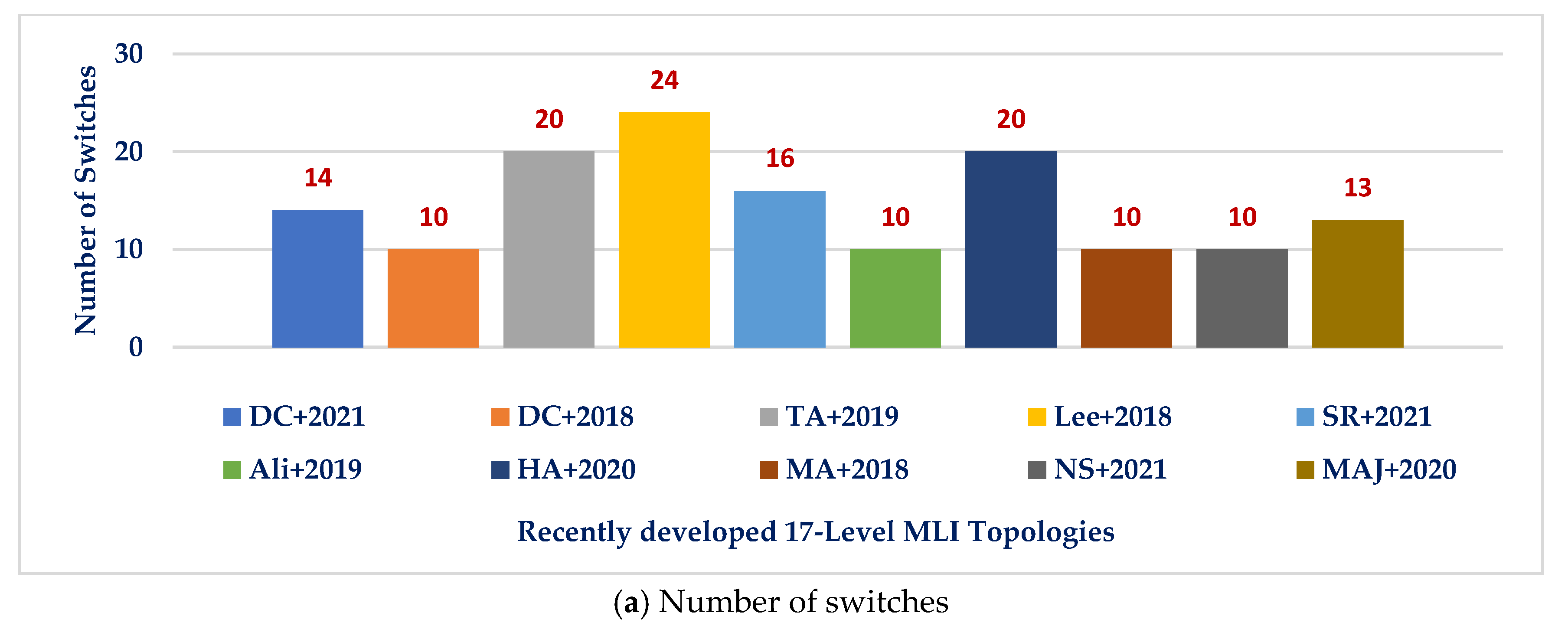
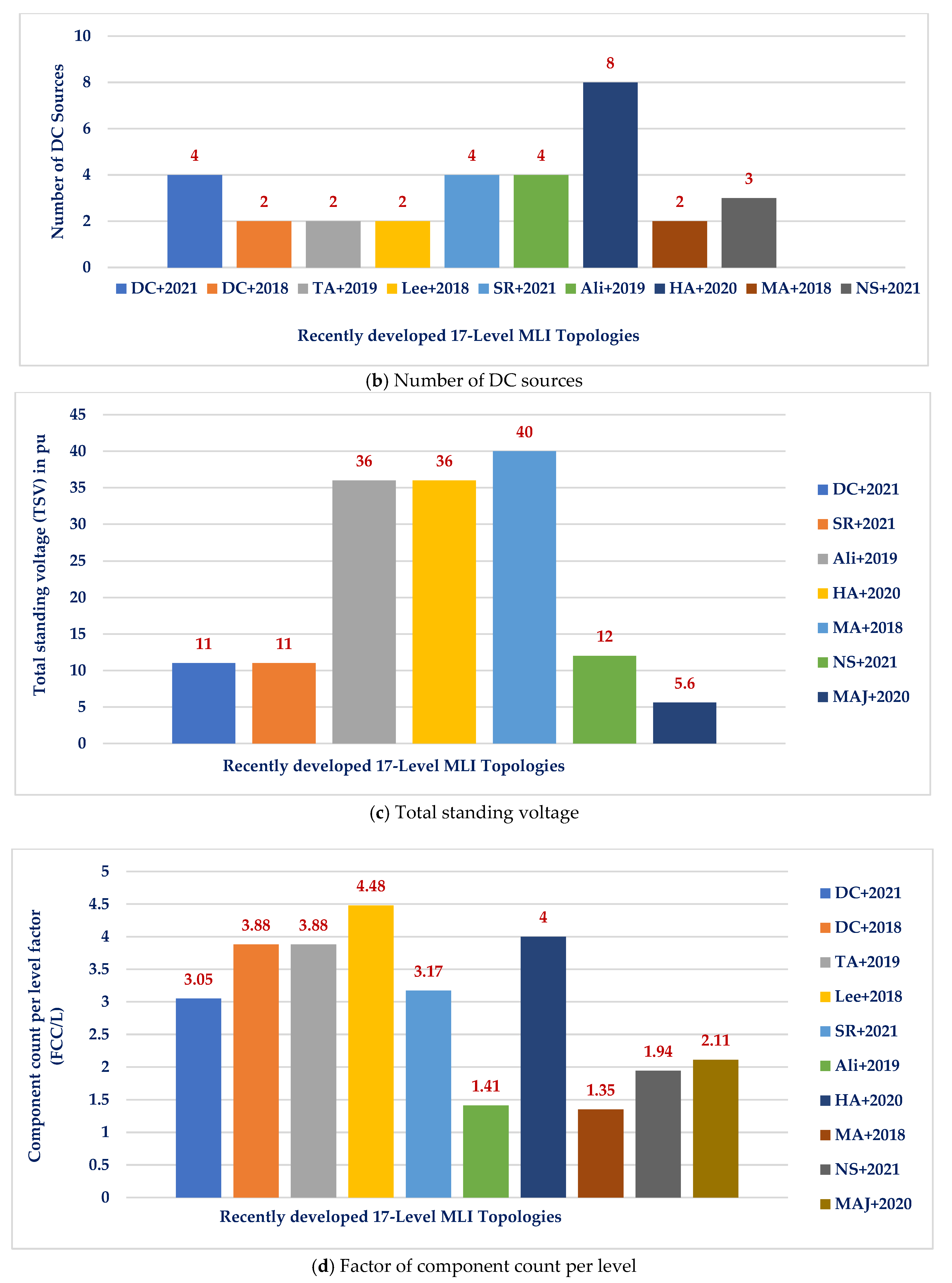
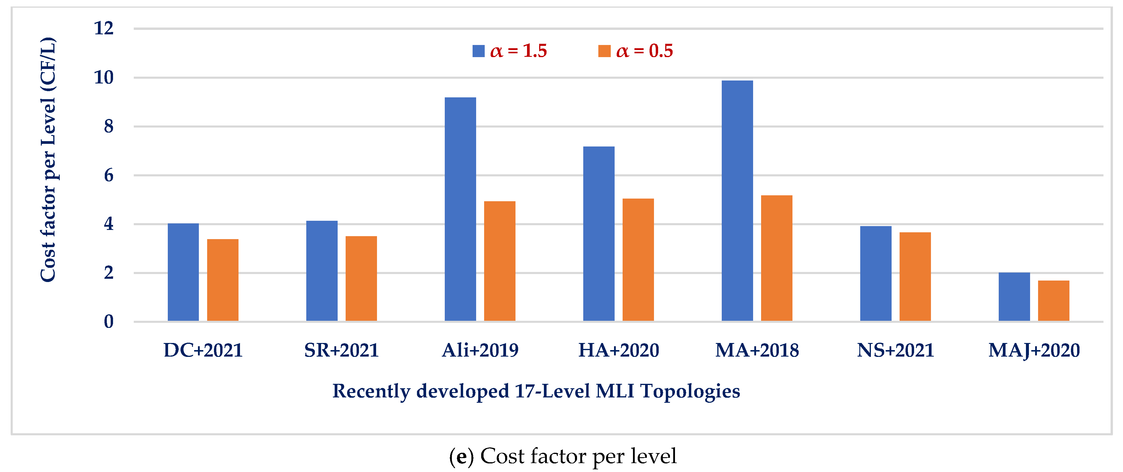
| Topologies | NSWT | NDCS | NL | NCAP | NDK | TSVPU | Transformer-Less Interfacing Capability | Leakage Current Limiting Capability | FCC/L | CF/L | |
|---|---|---|---|---|---|---|---|---|---|---|---|
| α = 1.5 | α = 0.5 | ||||||||||
| [3] | 14 | 4 | 17 | 4 | 14 | 11 | No | No | 3.05 | 4.02 | 3.38 |
| [138] | 10 | 2 | 17 | 4 | 20 | - | No | No | 3.88 | - | - |
| [139] | 20 | 2 | 17 | 4 | 20 | - | No | No | 3.88 | - | - |
| [140] | 24 | 2 | 17 | 4 | 24 | - | No | No | 4.48 | - | - |
| [5] | 16 | 4 | 17 | 4 | 14 | 11 | No | No | 3.17 | 4.14 | 3.5 |
| [141] | 10 | 4 | 17 | 0 | 10 | 36 | No | No | 1.41 | 9.18 | 4.94 |
| [142] | 20 | 8 | 17 | 0 | 20 | 36 | No | No | 4 | 7.17 | 5.05 |
| [143] | 10 | 2 | 17 | 0 | 10 | 40 | No | No | 1.35 | 9.88 | 5.18 |
| [134] | 10 | 3 | 17 | 0 | 10 | 12 | No | No | 1.94 | 3.92 | 3.66 |
| 17-Level SC-MLI [144] | 13 | 0 | 17 | 4 | 13 | 5.6 | Yes | Yes | 2.11 | 2.02 | 1.69 |
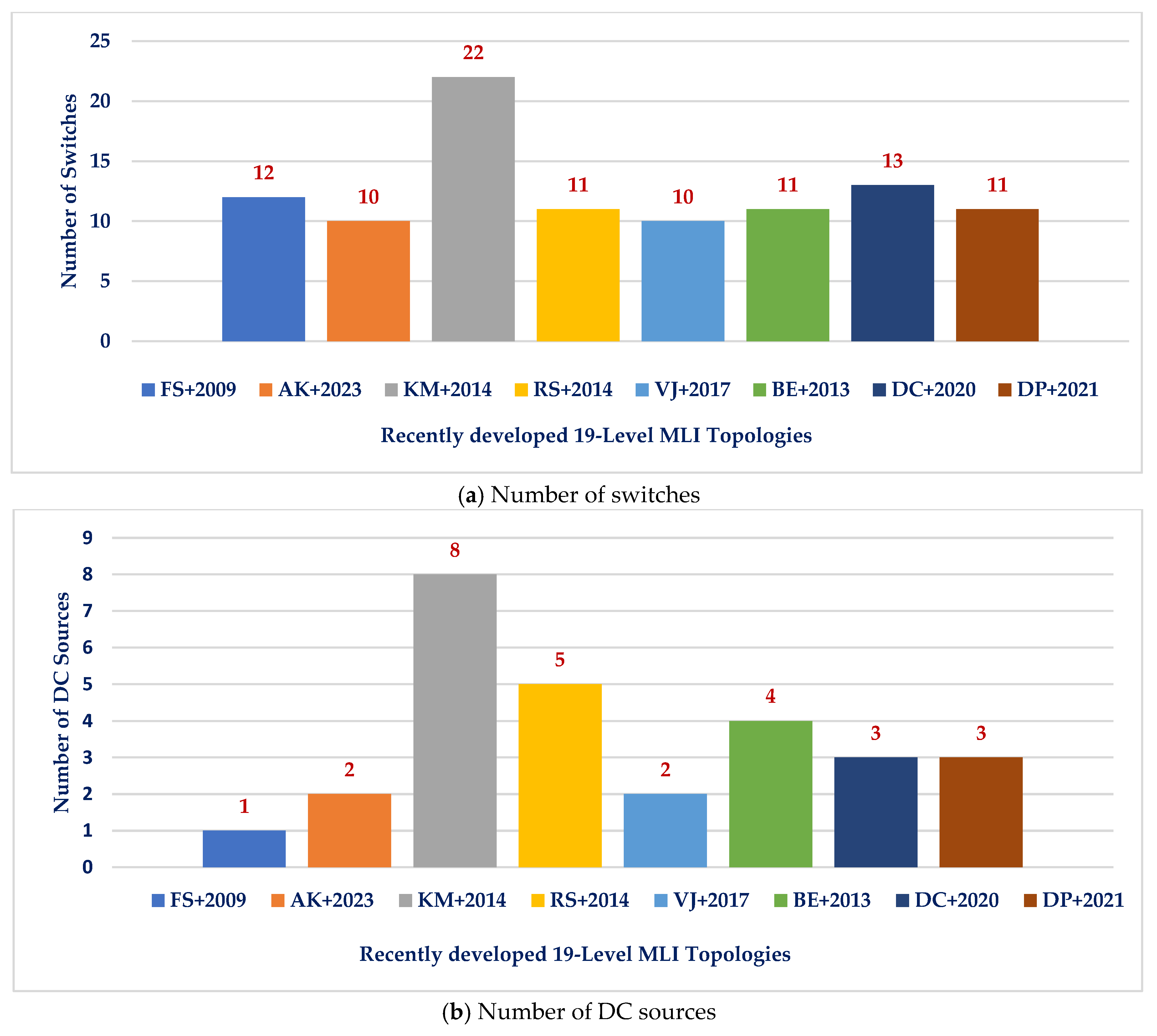
| Topologies | NL | NSWT | NDK | NDCS | FCC/L | TSVPU | Efficiency (%) | CF/L | |
|---|---|---|---|---|---|---|---|---|---|
| α = 0.5 | α = 1.5 | ||||||||
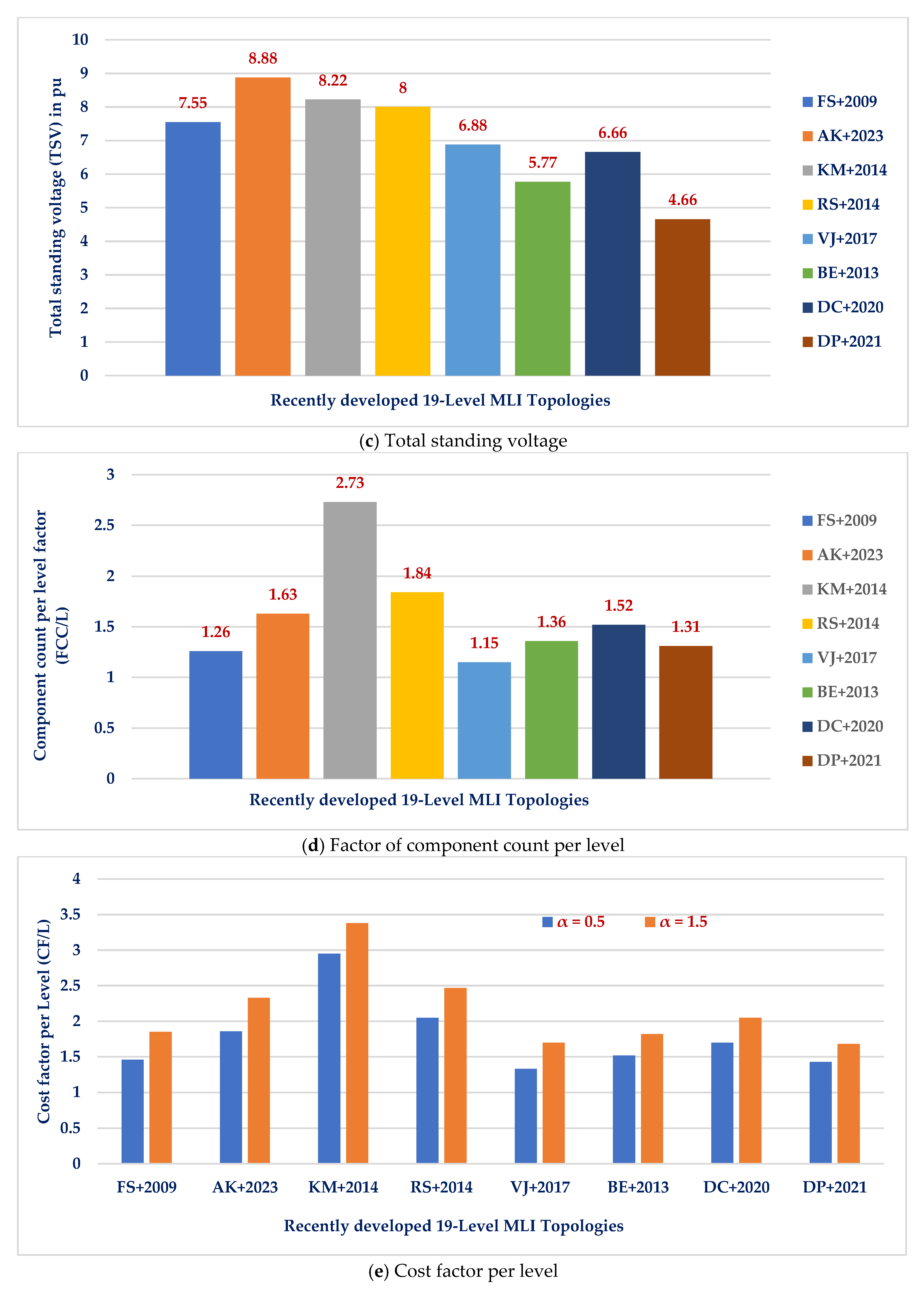
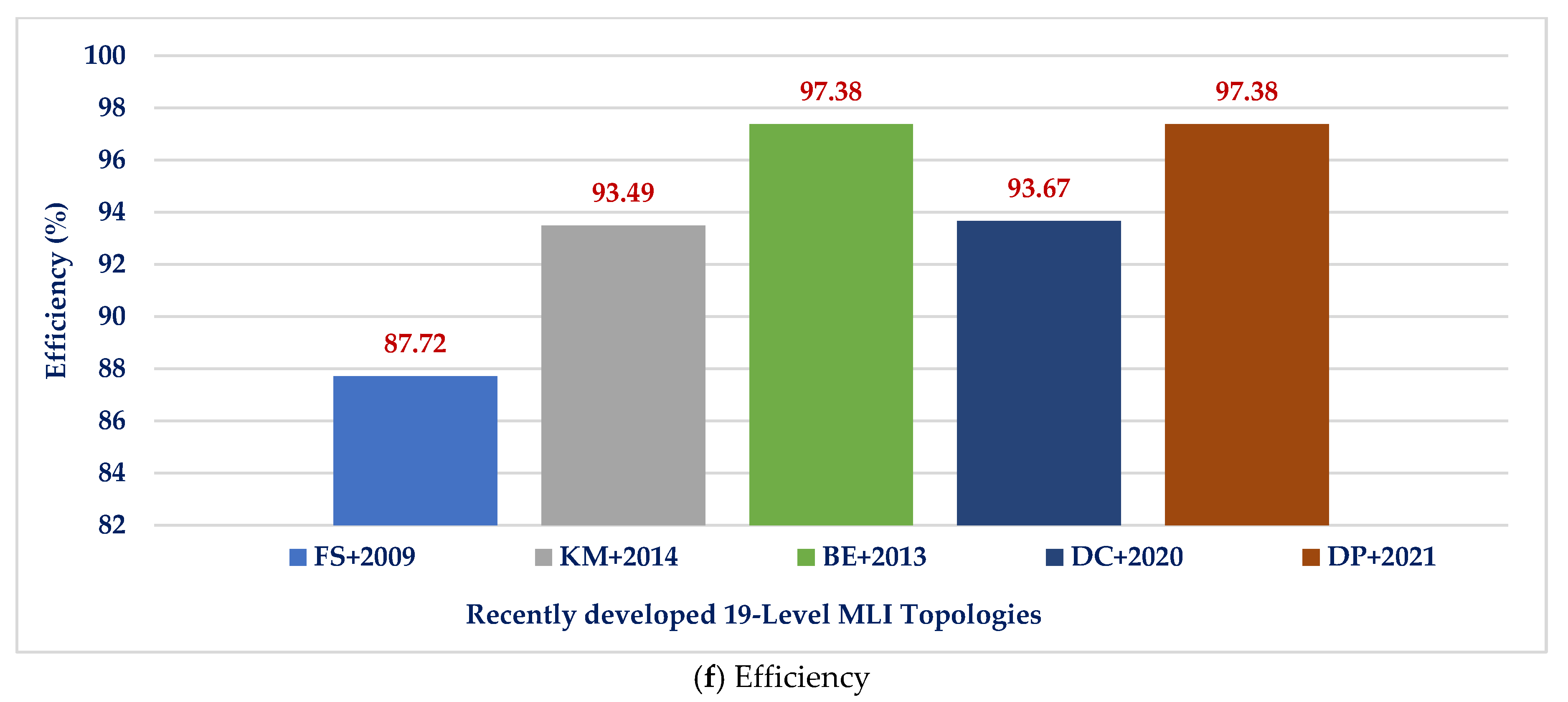
| [145] | 19 | 12 | 11 | 1 | 1.26 | 7.55 | 87.72 | 1.46 | 1.85 |
| [146] | 19 | 10 | 19 | 2 | 1.63 | 8.88 | - | 1.86 | 2.33 |
| [147] | 19 | 22 | 22 | 8 | 2.73 | 8.22 | 93.49 | 2.95 | 3.38 |
| [148] | 19 | 11 | 19 | 5 | 1.84 | 8 | - | 2.05 | 2.47 |
| [149] | 19 | 10 | 10 | 2 | 1.15 | 6.88 | - | 1.33 | 1.7 |
| [150] | 19 | 11 | 11 | 4 | 1.36 | 5.77 | 97.38 | 1.52 | 1.82 |
| [136] | 19 | 13 | 13 | 3 | 1.52 | 6.66 | 93.67 | 1.70 | 2.05 |
| [135] | 19 | 11 | 11 | 3 | 1.31 | 4.66 | 97.38 | 1.43 | 1.68 |
| Type of SC-MLI | No. of Levels/THD | Overall Voltage Gain/Caps Voltage | TSV (pu)/MVS | Reported Rated Efficiency | No. of Components | ||
|---|---|---|---|---|---|---|---|
| S | D | C | |||||
| FB based [153] | 7/19.5% | 3/VDC (3) | 6/3VDC | 85%@1kHz/5W | 10 | 0 | 3 |
| HB based [169] | 7/7% | 3/VDC (2) | 5.66/3VDC | 92.2%@50Hz/500W | 9 | 4 | 2 |
| HB/NPP based [172] | 7/16.2% | 1.5/0.5VDC (2) | 6/VDC | 95.5%@50Hz/250W | 10 | 0 | 2 |
| HB based [173] | 7/11.2% | 4/VDC (2), 2VDC (2) | 5.5/4VDC | 96.5%@50Hz/270W | 12 | 0 | 4 |
| HB based [162] | 7/13.7% | 1.5/VDC (2) | 5.33/VDC | 96.6%@50Hz/600W | 10 | 0 | 2 |
| FB based [151] | 7/2.8% | 3/VDC (2) | 6/3VDC | 92.1%@50Hz/150W | 9 | 1 | 2 |
| FB based [174] | 9/3.1% | 2/VDC (2) | 5.75/2VDC | 94.2%@1kHz/200W | 9 | 2 | 2 |
| FB based [175] | 9/13.8% | 4/VDC (1), 2VDC (1) | 5.25/4VDC | NA%@50Hz/NA | 9 | 2 | 2 |
| HB/NPP based [176] | 9/12.5% | 2/0.5VDC (2) | 5.5/2VDC | NA%@50Hz/400W | 11 | 0 | 2 |
| HB/NPP based [36] | 9/8.8% | 2/VDC (1), 0.5VDC (2) | 5.5/2VDC | 97.4%@50Hz/1kW | 12 | 0 | 3 |
| HB/NPP based [37] | 9/10.2% | 2/VDC (1), 0.5VDC (2) | 5.5/2VDC | 98%@50Hz/1kW | 10 | 1 | 3 |
| HB based [165] | 11/6.8% | 5/VDC (2), 3VDC (2) | 5/6VDC | 95.5%@50Hz/220W | 9 | 4 | 4 |
| HB based [166] | 13/11% | 6/VDC (2), 3VDC (2) | 5.5/6VDC | 95.5%@50Hz/500W | 10 | 4 | 4 |
| HB/NPP based [177] | 13/5.3% | 3/VDC (2), 0.5VDC (2) | 6/3VDC | NA%@50Hz/1kW | 12 | 4 | 3 |
| HB based [178] | 13/7.2% | 6/VDC (2), 3VDC (1) | 6/3VDC | NA%@50Hz/NA | 13 | 2 | 3 |
| HB based [38] | 13/7.7% | 6/VDC (1), 2VDC (2) | 5/3VDC | 94%@50Hz/1kW | 15 | 0 | 3 |
| HB/NPP based [160] | 17/NA | 8/VDC (2), 2VDC (2), 4VDC (2) | 4.25/8VDC | 95.5%@50Hz/1kW | 10 | 4 | 6 |
| HB based [179] | 17/3.9% | 8/VDC (1), 2VDC (2), 4VDC (2) | 4.25/8VDC | 94.5%@50Hz/80W | 10 | 5 | 5 |
| HB based [180] | 21/4.8% | 10/VDC (2), 2VDC (4), 4VDC (2) | 5/2VDC | NA%@50Hz/NA | 20 | 8 | 8 |
| HB based [181] | 21/4.5% | 10/VDC (2), 2VDC (4), 4VDC (2) | 5/2VDC | NA%@50Hz/NA | 20 | 12 | 10 |
| Type of SC-MLI | No. of Levels/THD | Overall Voltage Gain/CapsVoltage | TSV (pu)/MVS | Asymmetric Amplitude of DC-Sources | No. of Components | ||
|---|---|---|---|---|---|---|---|
| S | D | C | |||||
| SCC-Mode-I [43] | 11/NA | 1.25/VDC | 4.2/4VDC | VDC and 3VDC | 11 | 0 | 1 |
| SCC-Mode-II [43] | 11/9.3% | 1.67/2VDC | 4.4/2VDC | VDC and 2VDC | 11 | 0 | 1 |
| Figure 1 [49] | 15/4.7% | 1.75/VDC | 8.5/7VDC | VDC and 3VDC | 10 | 1 | 1 |
| Figure 1 [47] | 17/4.8% | 1.6/2VDC, 1.5VDC (1) | 4.5/8VDC | 2VDC and 3VDC | 12 | 1 | 3 |
| Figure 1 [44] | 19/8.9% | 1.8/4VDC (2) | 4.89/9VDC | VDC and 4VDC | 13 | 0 | 2 |
| Figure 1 [47] | 21/4.3% | 2/VDC (2), 4VDC (2) | 5/10VDC | VDC and 4VDC | 14 | 0 | 4 |
| Figure 1 [52] | 25/1.8% | 2/VDC, 4VDC | 10/10VDC | VDC and 5VDC | 12 | 2 | 2 |
| Figure 3 [44] | 29/NA | 2/VDC (2), 2.5VDC | 4.64/14VDC | VDC and 2.5VDC | 18 | 0 | 3 |
| Figure 12 [182] | 31/NA | 4/VDC (2), 4VDC (2) | 5.5/15VDC | VDC and 4VDC | 14 | 2 | 4 |
| Figure 13f SCC [183] | 31/NA | 3/VDC (2), 4VDC (2) | 5.6/15VDC | VDC and 4VDC | 16 | 0 | 4 |
| Figure 13g SCC [184] | 49/NA | 4/VDC (3), 4VDC (3) | 7.25/24VDC | VDC and 4VDC | 18 | 2 | 6 |
| Figure 3 [185] | 49/NA | 2/VDC (2), 5VDC (2) | 6/24VDC | VDC and 5VDC | 18 | 2 | 4 |
| Figure 4 [44] | 49/NA | 2/VDC (2), 5VDC (2) | 5/24VDC | VDC and 5VDC | 20 | 0 | 4 |
| Topologies | NLev | NSwt | NDK | NDC | NC | NDio | VTB/NL | Efficiency (%) |
|---|---|---|---|---|---|---|---|---|
| [187] | 15 | 10 | 10 | 5 | 0 | 1.26 | - | 93.73 |
| [188] | 15 | 14 | 14 | 1 | 4 | 1.63 | 4.86 | - |
| [189] | 15 | 10 | 9 | 4 | 0 | 2.73 | 4.6 | 97.5 |
| [190] | 15 | 8 | 8 | 3 | 0 | 1.84 | 2 | 95.2 |
| [191] | 15 | 10 | 9 | 3 | 0 | 1.15 | 2.26 | - |
| [192] | 15 | 10 | 10 | 5 | 0 | 1.36 | 1.06 | 90 |
| Figure 1 [186] | 15 | 10 | 8 | 2 | 2 | 1.31 | 3.6 | 96.3 |
| Type of SC-MLI | No. of Levels/THD | TSV (pu)/MVS | Reported Rated Efficiency | No. of Components | ||
|---|---|---|---|---|---|---|
| S | D | C | ||||
| SC [56,159] | 4/41.4% | 2.66/1.5VDC | 97%@1kW | 4 | 2 | 4 |
| ABNPC [57] | 5/NA | 5/VDC | 98.5%@1.2kW | 6 | 2 | 3 |
| ABNPC [60] | 5/NA | 6/0.5VDC | NA@50W | 10 | 0 | 3 |
| ABNPC [62] | 5/NA | 6/0.5VDC | 97.5%@800W | 6 | 2 | 4 |
| ABNPC [81] | 5/NA | 6/1.5VDC | 97.1%@1kW | 8 | 2 | 4 |
| ABNPC [82] | 6/20.2% | 4.4/3VDC | 95.8%@450W | 6 | 4 | 5 |
| Sym SC [172] | 7/12.2% | 5/VDC | 97%@150W | 9 | 1 | 3 |
| ABNPC [61] | 7/NA | 5.33/VDC | 96%@50W | 9 | 0 | 3 |
| ABNPC [66] | 7/19.3% | 5.3/2VDC | 96.7%@250W | 9 | 0 | 3 |
| Dual T-type [70] | 7/NA | 7.33/2VDC | 98%@100W | 10 | 0 | 4 |
| ABNPC [71] | 7/NA | 6.66/VDC | 97%@100W | 10 | 0 | 4 |
| ABNPC [74] | 7/NA | 4.66/VDC | 97.8%@400W | 8 | 2 | 4 |
| Dual T-type [61] | 9/NA | 10/VDC | 96%@50W | 12 | 0 | 3 |
| ABNPC [72] | 9/NA | 5/0.5VDC | 97%@500W | 10 | 4 | 4 |
| ABNPC [73] | 9/NA | 10/2VDC | 98%@400W | 11 | 4 | 3 |
| ABNPC [75] | 9/4.1% | 5/VDC | 97.1%@400W | 10 | 2 | 2 |
| Asym SC [56] | 15/5.5% | 5/2VDC | 97%@150W | 12 | 2 | 4 |
| 9-Level SC-MLI [198] | 9/1.07% | 8.5 VDC | 98.03%@583.91W | 10 | 4 | 4 |
| 15-Level MC-MLI [199] | 15/5.66% | 7 VDC | 94.1%@113.75W | 9 | 4 | 3 |
| MM-STC [200] | 9/9.28% | 4 VDC | 98.65%@321.35W | 8 | 8 | 0 |
| 17-Level SC-MLI [201] | 17/NA | 5/2VDC | 96.5%@434.7W | 16 | 10 | 4 |
| Type of SC-MLI | No. of Levels/THD | Overall Voltage Gain/Caps Voltage | TSV (pu)/MVS | Reported Rated Efficiency | No. of Components | ||
|---|---|---|---|---|---|---|---|
| S | D | C | |||||
| [86] | 5/NA | 2/VDC (1), 2VDC (1) | 4.5/2VDC | 98.1%@600W | 6 | 2 | 2 |
| [89] | 5/NA | 2/VDC (1), 2VDC (1) | 6/2VDC | 96%@40W | 7 | 2 | 2 |
| [90] | 5/35.4% | 2/VDC (2) | 5/2VDC | 98%@600W | 8 | 1 | 2 |
| [92] | 5/NA | 2/VDC (1), 2VDC (1) | 5/2VDC | 98%@600W | 11 | 0 | 4 |
| [93] | 5/NA | 2/VDC (1), 2VDC (1) | 6.5/2VDC | 97.5%@600W | 8 | 2 | 3 |
| [94] | 5/NA | 2/VDC (2) | 5.5/2VDC | 98.3%@600W | 8 | 0 | 2 |
| [99] | 5/36.4% | 2/VDC (1), 2VDC (1) | 6.5/2VDC | 97.5%@330W | 8 | 1 | 2 |
| [102] | 5/NA | 2/VDC (2) | 6/2VDC | 96.7%@1kW | 9 | 0 | 2 |
| [102] | 5/NA | 1/0.5VDC (2) | 6/VDC | 97%@500W | 6 | 1 | 2 |
| [94] | 7/NA | 3/VDC (3) | 6/3VDC | 98.3%@600W | 11 | 0 | 2 |
| [95] | 7/NA | 3/VDC (2), 2VDC (1), 3VDC (1) | 6/3VDC | 98%@800W | 6 | 4 | 4 |
| [97] | 7/NA | 3/VDC (1), 2VDC (2) | 5.33/3VDC | NA@1kW | 8 | 4 | 3 |
| [98] | 9/NA | 4/VDC (4) | 6/4VDC | NA@275W | 17 | 4 | 4 |
| [102] | 9/NA | 4/VDC (4) | 6/4VDC | NA@1kW | 17 | 0 | 4 |
| Type of SCMLI | No. of Levels/THD | Overall Voltage Gain/Caps Voltage | TSV (pu)/MVS | Reported Rated Efficiency | No. of Components | ||
|---|---|---|---|---|---|---|---|
| S | D | C | |||||
| CGSC based [105] | 5/NA | 1/VDC (1), 0.5VDC (1) | 4/VDC | 95.8%@1.2kW | 6 | 1 | 2 |
| ABNPC based [106] | 7/NA | 1/0.5VDC (2), VDC (1), 0.5VDC (1) | 5/VDC | 98%@2.2kW | 8 | 2 | 4 |
| ABNPC based [107] | 7/NA | 1/0.5VDC (2), VDC (1), 0.5VDC (1) | 5.5/VDC | NA | 10 | 0 | 4 |
| ABNPC based [112] | 7/NA | 0.5/0.5VDC (2), 0.33VDC (2) | 6/0.5VDC | NA | 11 | 0 | 4 |
| HB based [108] | 9/NA | 2/VDC (2), 0.5VDC (1) | 6/2VDC | 96.4%@500W | 8 | 2 | 3 |
| HBSC based [109] | 9/13.5% | 2/VDC (1), 0.5VDC (1) | 6/VDC | 97.3%@330W | 11 | 0 | 2 |
| HBSC based [110] | 9/NA | 2/VDC (1), 0.5VDC (1) | 5/2VDC | 96.5%@330W | 8 | 1 | 2 |
| HBSC based [111] | 9/NA | 2/VDC (1), 0.5VDC (1) | 5.5/2VDC | 96.6%@600W | 8 | 1 | 2 |
| HBSC based [114] | 9/9.4% | 2/VDC (1), 0.5VDC (1) | 5.5/VDC | 96.5%@800W | 10 | 0 | 2 |
| CGSC based [116] | 9/NA | 2/VDC (2), 0.5VDC (1) | 5/2VDC | 97.5%@1.2kW | 9 | 1 | 3 |
| CGSC based [117] | 5/NA | 2/VDC (1), 2VDC (1) | 6/2VDC | 97.5%@700W | 7 | 2 | 2 |
| Advantages | Switched-Capacitor Multilevel Inverters (SC-MLIs) [36,38,68,90,91,99,151,198,201] | Conventional Multilevel Inverters (DC-MLI, FC-MLI & CHB-MLI) [1,2,11,31,39,106,205] |
|---|---|---|
| Reduced component count | Fewer power electronic components required | More components needed |
| Cost | Fewer components lead to lower costs and increased reliability | A higher component count might lead to increased cost and complexity |
| Higher efficiency | Fewer components and simplified control can contribute to higher efficiency | Higher component count and more complex control might lead to lower efficiency |
| Compact design | Modular and compact designs are possible | The size might be larger |
| Modular structure | Scalable and adaptable design by adding or removing capacitor modules | Limited scalability |
| Simplified control | Simple control strategy due to switched capacitors | Control complexity may be higher |
| Voltage balancing | Inherent voltage balancing | Requires active balancing |
| Improved reliability | A simpler structure and fewer components can result in improved overall reliability | Complex structures and more components might lead to increased failure points |
| Reduced EMI | Potentially lower EMI | EMI considerations may be higher |
| Low-power applications | Well-suited for applications with lower power requirements | Suitable for a range of power levels, but complexity might be overkill for lower power applications |
| Improved waveform quality | Inherent voltage balancing leads to improved output waveform quality | Output waveform might require additional filtering to achieve desired quality. |
| MLI Topology | Benefits | Restrictions |
|---|---|---|
| RVDC-C [205] |
|
|
| Developed H-bridge [31] |
|
|
| SCU [151] |
|
|
| DCC [1] |
|
|
| CPCC [205] |
|
|
| CIC [205] |
|
|
| Hybridtopology [31,43,51] |
|
|
| HERC-C [205] |
|
|
| Cascaded half- bridge [11,33] |
|
|
| SSSC [151] |
|
|
| SADC [151] |
|
|
| CCS [11,33] |
|
|
| Staircase cascaded [33] |
|
|
| Reduced switch type [205] |
|
|
| Cascade unit based [11] |
|
|
| MLI Type | Applications |
|---|---|
| NPC [72,79] |
|
| FC [205] |
|
| ANPC [57] |
|
| CHB [11,33] |
|
| HCHB [31,43,51] |
|
| MLDCL [12] |
|
| SSPS [151] |
|
| T-type [68] |
|
| N-type [1] |
|
| CCHB [1,11,33] |
|
| RV [2,205] |
|
| MLM [205] |
|
| CCS [11,33] |
|
| PUC [205] |
|
| CBSC [151,205] |
|
| M-type [1] |
|
| Topology | Unidirectional Switches (Nsw) | Bidirectional Switches | DC Sources (NDC) | Capacitors (Ncap) | H-Bridge | Highest Switch Rating | Total StandingVoltage Requirement (p.u.) |
|---|---|---|---|---|---|---|---|
| CHB-MLI [11,31] | 2 ∗ (nlevel − 1) | 0 | 0 | - | VDC | 2 ∗ (nlevel − 1) ∗ VDC | |
| NPC-MLI [72,73] | 2 ∗ (nlevel − 1) | 0 | 1 | (nlevel −1) | No | VDC | 2 ∗ (nlevel − 1) ∗ VDC |
| FC-MLI [205] | 2 ∗ (nlevel − 1) | 0 | 1 | ∗ (nlevel − 1) | No | 2 ∗ VDC | 2 ∗ (nlevel − 1) ∗ VDC |
| RVDC-MLI [1,2] | 3 ∗ (nlevel − 1) | 0 | 0 | No | 2 ∗ VDC | ∗ (nlevel − 1) ∗ VDC | |
| H-bridge MLI [31,45,51] | 2 ∗ (log2 (nlevel + 1)) | 0 | (log2 (nlevel +1) −1) | 0 | No | ∗ VDC | 2 ∗ (nlevel − 1) ∗ VDC |
| SCU-MLI [151,205] | 3 ∗ (log3 ( )) + 4 | 0 | Log3 ( ) | log3 ∗ ( ) | Yes | ∗ VDC | ∗ (nlevel −1) ∗ VDC |
| DCC-MLI [1,2,133] | 0 | 0 | Yes | 3 ∗ VDC | ∗ VDC | ||
| CPCC-MLI [11,33,205] | 0 | No | ∗ (nlevel −1) ∗ VDC | ||||
| CIC-MLI [11] | 0 | 0 | No | 2 ∗ VDC | (3 ∗ nlevel −7) ∗ VDC | ||
| Hybrid MLI [31,43,51] | No | 2 ∗ VDC | ∗ (nlevel − 1) ∗ VDC | ||||
| HERC-MLI [11,33,205] | 1 | 0 | No | 2 ∗ VDC | ∗ (nlevel − 1) ∗ VDC | ||
| CHB-MLI [11] | (nlevel + 1) | 0 | 1 | No | 2 ∗ VDC | (nlevel +3) ∗ VDC | |
| SSSC-MLI [151] | (5 ∗ nlevel − 1) | 0 | 1 | (nlevel − 1) | No | VDC | (5 ∗ nlevel − 1) ∗ VDC |
| SADC-MLI [151,205] | 0 | No | 10 ∗ VDC | ∗ (nlevel − 1) ∗ VDC | |||
| CCS-MLI [33,205] | 6 | 2 | + 2 | No | 2 ∗ VDC | ∗ (nlevel − 1) ∗ VDC | |
| RSC-MLI [205] | 6 | 0 | Yes | 2 ∗ VDC | ∗ (nlevel − 1) ∗ VDC |
| SI. No. | Components | Failure Rate (Failures/Hour) |
|---|---|---|
| 1. | Switches | 250 × 10−9 |
| 2. | Diodes | 100 × 10−9 |
| 3. | Capacitors | 300 × 10−9 |
| Components | NPC [103] | FC [103] | CHB [103] |
|---|---|---|---|
| IGBTs | 4800 (12) | 4800 (12) | 1200 (12) |
| Capacitors | 600 (2) | 1500 (5) | 1200 (3) |
| Diodes | 1800 (18) | 1200 (12) | 1200 (12) |
| Total FITs | 7200 | 7500 | 3600 |
| Failure rate (failure/106 h) | 7.2 | 7.5 | 3.6 |
| MTTF (hours) | 138,888 | 133,333 | 277,777 |
| Grid-Fault Conditions (Challenges) | Multilevel Inverter Response (Recommendations) |
|---|---|
| Overvoltage [34,163] |
|
| Under voltage [34,163] |
|
| Frequency deviation [34,163,194] |
|
| Voltage sag [163,194] |
|
| Voltage swell [163,194] |
|
| Grid disconnect [163,194] |
|
| Short circuit [34,163,194] |
|
| Grid outage [34,163,194] |
|
| Harmonic distortion [34,163,194] |
|
Disclaimer/Publisher’s Note: The statements, opinions and data contained in all publications are solely those of the individual author(s) and contributor(s) and not of MDPI and/or the editor(s). MDPI and/or the editor(s) disclaim responsibility for any injury to people or property resulting from any ideas, methods, instructions or products referred to in the content. |
© 2023 by the authors. Licensee MDPI, Basel, Switzerland. This article is an open access article distributed under the terms and conditions of the Creative Commons Attribution (CC BY) license (https://creativecommons.org/licenses/by/4.0/).
Share and Cite
Nyamathulla, S.; Chittathuru, D. A Review of Multilevel Inverter Topologies for Grid-Connected Sustainable Solar Photovoltaic Systems. Sustainability 2023, 15, 13376. https://doi.org/10.3390/su151813376
Nyamathulla S, Chittathuru D. A Review of Multilevel Inverter Topologies for Grid-Connected Sustainable Solar Photovoltaic Systems. Sustainability. 2023; 15(18):13376. https://doi.org/10.3390/su151813376
Chicago/Turabian StyleNyamathulla, Shaik, and Dhanamjayulu Chittathuru. 2023. "A Review of Multilevel Inverter Topologies for Grid-Connected Sustainable Solar Photovoltaic Systems" Sustainability 15, no. 18: 13376. https://doi.org/10.3390/su151813376