Article

Spatial Effect Analysis of a Long Strip Pit Partition Wall and Its Influence on Adjacent Pile Foundations

School of Civil Engineering and Architecture, Zhejiang University of Science and Technology, Hangzhou 310023, China
*
Author to whom correspondence should be addressed.
Sustainability 2023, 15(13), 10409; https://doi.org/10.3390/su151310409
Submission received: 7 June 2023 / Revised: 23 June 2023 / Accepted: 29 June 2023 / Published: 1 July 2023
(This article belongs to the Special Issue Advancing Sustainability in Geotechnical Engineering)

Abstract

:
The spatial effect at the end of the foundation pit partition wall is significant, and the displacement of the retaining wall and soil caused by its demolition leads to an additional displacement and bending moment of the adjacent pile foundations, which in turn deteriorates the work behavior of the pile foundation. Taking the project of an open tunnel under a viaduct located in Hangzhou as an example, site monitoring was performed to determine the effect of the demolition of the partition wall on the displacement of the surrounding retaining wall and the soil in the adjacent area and the monitoring data were compared to the finite element analysis results to check the rationality of the finite element model. This model was used to study the influence of the distance from the pile foundation to the partition wall as well as the stiffness of the retaining wall on the displacement and bending moment of the pile foundation during excavation. These results indicate that because of the support effect of the foundation pit partition wall on the retaining wall, the spatial effect at the end of the partition wall is large, and the displacement and bending moments of the pile foundation in the vicinity of the partition wall are lower than those in the far distance. Demolition of the partition wall will increase the displacement and bending moment of adjacent pile foundations, and this effect decreases with increasing distance. The range of influence of the spatial effect at the end of the partition wall is approximately 1.1 times the depth of the foundation pit. When the pile foundation is in the immediate vicinity of the partition wall, the response of the front-row and rear-row piles to the demolition of the partition wall is significantly different. The front row piles are more affected, while the rear row piles are less affected. As the distance increases, the difference in response gradually decreases and tends to be consistent. As the stiffness of the retaining wall increases, the effect of the demolition of the partition wall on the pile foundation decreases. It is recommended that the stiffness of the supporting system near the partition wall be reduced appropriately, and the partition wall should be set at the foundation pit section near the pile foundation, but the response of the foundation pit and the adjacent pile foundation should be paid close attention to when the partition wall is demolished.

1. Introduction

The unloading of foundation pit excavation can cause displacement of the surrounding soil in the direction of the foundation pit, and controlling its environmental impact is a concern for the sustainable development of foundation pit engineering. Long strip foundation pits are often fitted with partition walls, dividing the original pit into several smaller lengths for easy organization of the construction. Heish [1] analyzed the mechanical partition wall mechanism based on the continuous-beam elastic support method, indicating that the partition wall may have a strain-suppressing effect similar to the pit corner on the foundation pit. This indicates that there is a spatial effect at the end of the partition wall that is similar to the corner of a conventional foundation pit. This spatial effect is manifested by the smaller deformation of the foundation pit near the partition wall and the greater deformation away from the partition wall. In the study of the suppression of foundation pit deformation by partition walls, Ou et al. [2] compared engineering cases with and without partition walls and found that partition walls can significantly reduce the deformation of the retaining wall as well as the settlement of the surface at the rear of the wall. Wu [3] counted the deformation of retainment and surface settlement statistically for eleven groups of foundation pits with and without partition walls and found that the deformation of foundation pits with partition walls was significantly smaller than that of foundation pits without partition walls. Hsieh et al. [4,5] used the three-dimensional finite element method to study the influence of parameters such as length, spacing, and thickness of partition walls on the deformation of retaining walls and set out a computational formula for predicting the deformation of retaining walls during excavation of foundation pits with partition walls. Han et al. [6] studied the effect of partition walls on the deformation of foundation pits and adjacent buildings and found that partition walls can greatly reduce the deformation of retaining walls and the settlement of adjacent soil, thereby protecting adjacent buildings. Li et al. [7] studied the effect of partition walls on the settlement of adjacent buildings and found that the higher the stiffness and depth of embedment of the partition walls, the greater the inhibitory effect on the settlement of adjacent buildings. Wu et al. [8] conducted a finite element simulation of the excavation process of a long strip foundation pit that was partitioned using partition walls and found that the smaller the gap distance between the partition walls, the less the horizontal displacement of the retaining wall and the settlement of the soil outside the pit. In the study of spatial effects in foundation pits, Cheng et al. [9,10] compared the results of two-dimensional and three-dimensional analyses of the excavation of foundation pits in areas of soft soil and found that the displacement of the retaining wall at the corner of the pit was significantly greater in the results of the two-dimensional analysis. Finno [11,12] summarized the characteristics of the three-dimensional ground displacement in the surrounding area caused by the excavation through a statistical analysis of a large number of results from the numerical calculation of the engineering of the foundation pit. Fuentes et al. [13] proposed a formula for estimating the effect of corner spatial effects on adjacent buildings in foundation pits and verified it via practical engineering cases. Szepesházi et al. [14] studied the variation of the internal force of the retaining structure in the region of the concave corner during the excavation of the foundation pits. Abbas et al. [15] performed a three-dimensional finite element analysis of retaining wall deformation during the excavation of foundation pits with irregular shapes and found that the short side of the foundation pit is significantly affected by the corner spatial effect, even though the majority of the sectional strain on the long side is close to the results of the plane strain analysis. Russell et al. [16] implemented a three-dimensional analysis function to describe the surface settlement pit around the excavation at the deep foundation pit, and the maximum surface settlement at the rear of the resulting wall is located at the midpoint of the long side of the excavation. Wang et al. [17] conducted finite element analysis and indoor model tests on the spatial effect of slender foundation pits and obtained the spatial distribution pattern of additional soil pressure with retaining wall deformation. Li et al. [18,19] conducted a study of the deformation characteristics of irregular foundation pits using a combination of on-site monitoring and numerical simulations, and found that the pit coner has a restraining effect on the deformation of the diaphragm wall. Liu et al. [20] analyzed the displacement of the retaining wall, surface settlement, and surrounding building settlement data of large deep foundation pits, evaluated the spatial effect of the corners of the foundation pit using the analysis results, and optimized the support structure of the corners of the foundation pit, thereby reducing construction costs. Wu et al. [21] analyzed the deformation law of the retaining wall under the effect of spatial effects based on on-site monitoring data during the excavation process of foundation pits in soft soil areas. They found that the spatial distribution of surface settlement of the foundation pit and displacement of the retaining wall was larger on the long side and smaller on the corners. Liu et al. [22] established a numerical model for the deep foundation pit engineering of buried tunnels, believing that the pit angle of the foundation pit significantly limits the horizontal displacement and support axial force of the retaining wall. Jia et al. [23] used model tests to find that the spatial effect of smaller foundation pits is more pronounced than that of larger ones.
Based on the studies cited above, research on the spatial effects of partition walls has been quite extensive at present, mainly focusing on the distribution of displacement of foundation pit retaining walls and soil under the influence of spatial effects. There is relatively little research on the behavior and response of adjacent pile foundations under the influence of spatial effects. Before the demolition of the partition wall, the displacement of the retaining wall is limited by the support force of the partition wall, reducing the effect of excavation on the behavior of adjacent pile foundations. After the demolition of the partition wall, the supporting force of the partition wall on the retaining wall disappears, and the retaining wall further moves in the direction of the foundation pit. The movement of the soil behind the wall caused by this may lead to additional displacement and bending moments in the pile foundation in the adjacent area. In this paper, on-site monitoring data are used to obtain the surface settlement and deformation of the retaining walls before and after the partition wall of the long strip foundation pit is demolished, from which the rationality of the numerical finite-element model is verified. The model is applied to study the effect of key building variables such as the distance of the pile foundation from the partition wall and the stiffness of the retaining wall on the foundation of the adjacent pile. The spatial effect of the pit partition wall can be used to reduce the impact of excavation on the environment, and the proposal of pit support near the pit partition wall is put forward to achieve the sustainable development goal of the low environmental impact of foundation pit engineering.

2. Monitoring and Models

2.1. Project Overview

The open-cut tunnel is located in Hangzhou City, and it crosses the present viaduct in an east-west direction. The bridge adopts a clustered pile foundation with a pile length of about 55 m, and six bored piles (D = 1.8 m) are arranged under the bearing platform. The closest distance between the north side of the foundation pit and the pile foundation is about 5.1 m, and the closest distance to the south side is about 9.7 m. The planar relationship between the bearing platform and the foundation pit is shown in Figure 1. The excavation depth of the foundation pit is 15.4 m. The retaining structure is bored piers at φ900@1050 mm, and the waterproof structure is high-pressure rotary jet grouting piles at φ800@600 mm. The support inside the foundation pit is made of concrete, steel, and concrete from the top to the bottom of the pit. When excavated to 1.8 m, the first support is set with an 800 mm × 900 mm concrete support, the second support is a φ609 steel support, and the third support is made of concrete. The vertical spacing of the three supports is 5.12 m and 3.45 m from the top to the bottom. A partition wall is placed to divide the foundation pit into east and west areas for construction, which consists of a bored pile and a high-pressure rotary jet grouting pile. The depth of the partition wall is 25 m. The length of the foundation pit in the eastern area is 128 m, while the length of the foundation pit in the western area is 287 m, with a width of 32 m. After the western foundation pit has been excavated down to the bottom of the pit, it will be necessary to excavate the eastern foundation pit. After the east foundation pit is excavated to the bottom of the pit, the partition wall is demolished. The excavation of the eastern foundation pit is decomposed into five working conditions along the depth direction for the construction, as listed in Table 1.

2.2. Monitoring Scheme

The layout of the monitoring points is shown in Figure 1. Arrange eight horizontal displacement monitoring points for the retaining walls on both sides of the foundation pit. Five surface settlement monitoring points are buried behind the walls on both the north and south sides, with distances of 2 m, 5 m, 10 m, 15 m, and 25 m from the foundation pit. There are a total of eight surface settlement survey lines. The tilt measurement point closest to the partition wall (10 m east of the partition wall) is used for analysis. The tilt measurement point on the north side of the pit is marked Q1, and the tilt measurement point on the south side of the pit is marked Q2. Surface settlement monitoring points on the north side of the pit are marked as the D1 survey line, and surface settlement monitoring points on the south side of the pit are marked as the D2 survey line.

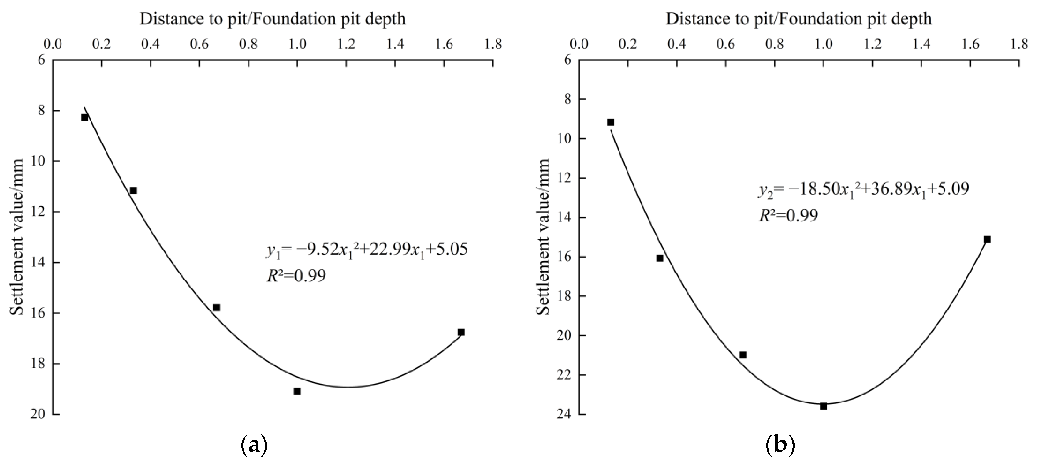
2.3. Analysis of Monitoring Results

The horizontal displacement of the retaining wall at typical section Q2 was analyzed, and the measured horizontal displacement values of the retaining wall along the depth direction under different working conditions are shown in Figure 2, with the wall displacement towards the pit being positive. From Figure 2, it can be seen that the horizontal displacement curves of the retaining wall under different working conditions have a similar shape, and the overall shape can be seen to be in the form of an “arc”. As the excavation depth increases, the horizontal displacement continues to increase, and the maximum horizontal displacement occurs continuously downward and approaches the bottom of the foundation pit, finally located at a depth of about 14 m. When it was excavated to the bottom of the pit, the maximum horizontal displacement of the retaining wall (condition 4) was found to be 26.43 mm, and following the removal of the partition wall (condition 5), the maximum horizontal displacement was 29.23 mm, an increase of about 11%. This is due to the vanishing of the supporting force on the retaining wall as a result of the demolition of the partition wall in Condition 5, which leads to a further displacement of the retaining wall into the pit.
By analyzing the monitoring data from the D1 and D2 survey lines to the north and south for surface settlement of the foundation pit, the distribution of surface settlement around the pit is plotted as a function of distance under different working conditions, as shown in Figure 3, with soil settlement as positive. As can be seen in Figure 3, the shape of the curve of the surface settlement distribution as a function of distance under different working conditions is similar, and the overall shape is an “inverted triangle”. The amount of settlement increases continuously as the depth of excavation increases, and maximal settlement occurs at a distance of about 15 m from the foundation pit, which is in accordance with the general law of settlement of the surface outside the pit in areas of soft soil. The surface settlement on the D2 survey line is about 24% greater than that on the D1 survey line. This is due to the presence of an external haulage road for the earthwork on the south side of the foundation pit, and the heavy traffic load has led to further surface settlement on the south side. When the foundation pit was excavated to the bottom (condition 4), the maximum surface settlement on survey line D1 was 16.91 mm. After the partition wall was demolished (condition 5), the maximum settlement was 19.09 mm, an increase of about 13%. When the foundation pit was excavated to the bottom (condition 4), the maximum surface settlement on survey line D2 was 21.95 mm. After the partition wall was demolished (condition 5), the maximum settlement reached 23.59 mm, an increase of about 7%. This is because, after the demolition of the partition wall, the supporting force of the partition wall on the retaining wall disappears, leading to further displacement of the retaining wall towards the pit and exacerbating the soil loss around the pit. As per the provisions of China’s GB50497-2009 “Technical code for monitoring of building excavation engineering” on the boundary values of the horizontal displacement at the depth of the retaining wall and the vertical displacement of the surrounding surface of the foundation pit, and combined with hydrogeological conditions in the region, the monitoring scheme for this project determines that the alarm values for the horizontal displacement at depth and for the surface settlement of the retaining wall are both 30 mm and the warning values are both 24 mm. From the analysis above, it can be seen that the maximum horizontal displacement of the retaining wall after the demolition of the partition wall at the Q2 measurement point was as high as 29.23 mm, which exceeds the warning value and is very near the alarm value. On the D2 survey line, the maximum surface settlement was 23.59 mm, which is close to the warning value.
According to the monitoring data of working condition 5 in Figure 3, Figure 4 shows a curve fit of the relationship between the amount of settlement and the ratio of the distance to the depth of the foundation pit. In agreement with Figure 4, the relation functions between the surface settlement of the D1 and D2 survey lines after the partition wall is demolished and the distance from the pit edge are obtained in the form of Equations (1) and (2), respectively:
y1 = −9.52x12 + 22.99x1 + 5.05
y2 = −18.50x12 + 36.89x1 + 5.09
where y1 and y2 represent surface settlement on survey lines D1 and D2, respectively, and x1 is the ratio of the distance from the edge of the foundation pit to the measurement point to the depth of the pit.
As shown in Figure 4, the goodness of fit coefficient R2 from Equations (1) and (2) reached 0.99, indicating strong agreement between the fitted relationship function and monitoring data. It is possible that Equations (1) and (2) better reflect the surface settlement pattern on survey lines D1 and D2 after the partition wall has been demolished. Based on the results of the calculations in Equations (1) and (2), the point of maximum surface settlement following the demolition of the partition wall is located at a distance of approximately 1 to 1.2 times the depth of the foundation pit relative to the pit edge.

2.4. 3D Finite Element Modeling

Using the finite element software Midas GTS NX, a numerical model of the tunnel foundation pit is established, as shown in Figure 5. Given the boundary effect of the model and the range of spatial effect [24], the size of the model is chosen to be 152 m long (perpendicular to the partition wall direction), 130 m wide (parallel to the partition wall direction), and 85 m deep. The length of the foundation pit in the eastern area is determined to be 80 m, while the length of the foundation pit in the western area is determined to be 72 m, with a width of 32 m and an excavation depth of 15.4 m. Horizontal constraints are imposed on the lateral sides of the model, vertical constraints on the bottom, and a free boundary on the top surface. The computational steps of the simulation are shown in Table 2.
The classification of soil layers and determination of physical and mechanical parameters based on the geologic survey report are shown in Table 3. Soil simulations were performed using solid elements and a modified constitutive Mohr-Coulomb model. The cushion cap is simulated using solid elements and buried 1.5 m below the ground according to the actual engineering situation. With an elastic modulus of 2.5 × 10⁴ MPa, Poisson’s ratio is 0.2. Beam elements were used for the support, waist beam, and link beam. For computational simplicity, the retaining wall was equivalent to a diaphragm wall on the principle of equivalent bending rigidity [25], and plate elements were used in the simulations. Table 4 shows the parameters of the structural calculation.

2.5. Model Rationality Verification

Figure 6 shows a cloud map of horizontal displacements of the retaining walls before and after the demolition of the partition wall. It can be seen in Figure 6 that after the partition wall is demolished, the horizontal displacement of the retaining wall near the end of the partition wall increases significantly. We compared the simulated and monitored values of the measurement point of the horizontal displacement Q2 of the retaining wall and the surface settlement survey line D2 before and after the demolition of the partition wall, and the results are shown in Figure 7 and Figure 8. From Figure 7, it can be seen that the simulated horizontal displacement of the retaining walls before and after the partition wall has been demolished is in fundamental agreement with the values obtained from the monitoring data, and maximum displacement occurs at a depth of approximately 14 m, with a difference of 0.017 mm and 0.024 mm between the simulated displacement value and the monitoring value of the maximum displacement. From Figure 8, it can be seen that the surface settlement curves obtained from both the simulation and the monitoring have the shape of an inverted triangle, with maximum surface settlement occurring at a distance of about 15 m from the edge of the foundation pit. The differences between the maximum simulated and monitored maximum surface settlement correspond to 0.586 mm and 0.534 mm, respectively. The agreement between the simulated and monitored values in the two working conditions before and after the partition wall demolition is therefore good, indicating that the numerical model is a reasonable model.

3. Results

The effects of the distance between the pile foundation and the partition wall as well as the thickness of the retaining wall on the displacement and bending moments of adjacent pile foundations were investigated using the validated finite element model. The northern pile foundation was taken for research purposes due to the proximity of the northern bearing platform to the foundation pit. For the pile group, the foundation of the western pile was marked as #1, #2, and #3 relative to the distance of the foundation pit from near to far. The location relationship is shown in Figure 1.

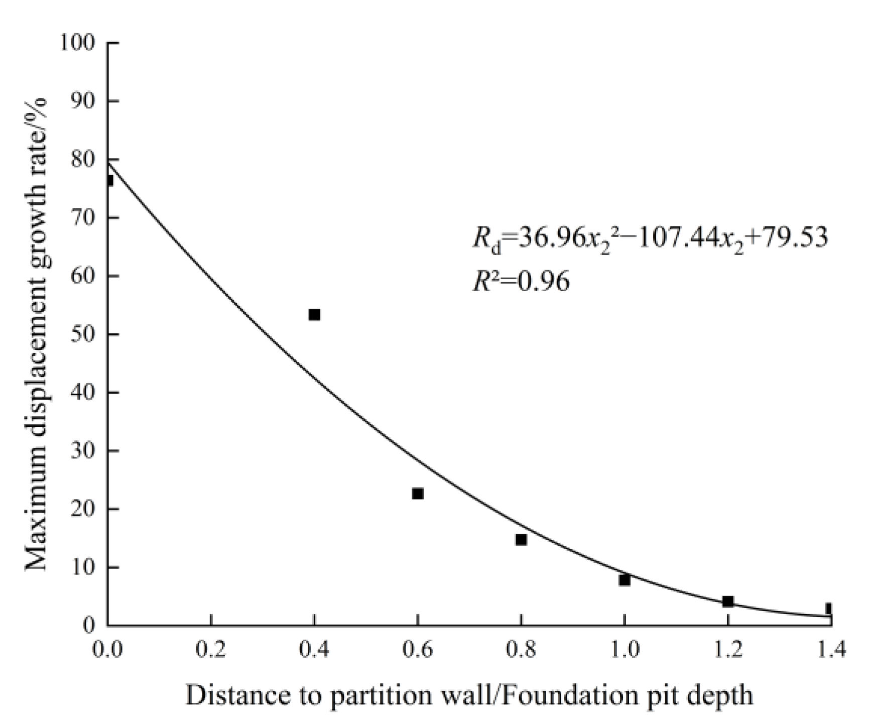
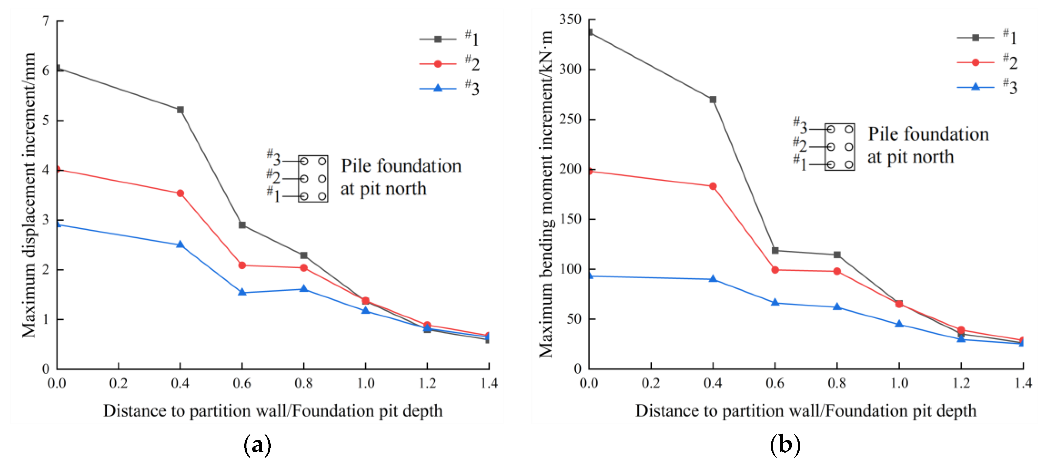
3.1. Analysis of the Effect of the Distance of the Pile Foundation from the Partition Wall

We compare and analyze seven cases in which the distance L from the centerline of the short side of the bearing platform to the partition wall is 0 m, 6 m, 9 m, 12 m, 15 m, 18 m, and 21 m, and the rest of the parameters are the same as the numerical model discussed above. The horizontal displacement and bending moment distributions of pile #1 are shown in Figure 9. The displacement of the pile foundation is positive when it moves towards the pit, and the bending moment is positive when the north surface of the pile foundation is pulled. The dashed line represents the working condition before the demolition of the partition wall, and the solid line represents the working condition after the partition wall is demolished. Figure 9 shows the curve fit of the relationship between the maximum displacement value of the pile foundation before and after the demolition of the partition wall and the distance, as can be seen in Figure 10. This figure takes the ratio of the distance to the depth of the foundation pit as the horizontal axis and the value of the maximum displacement of the pile foundation as the vertical axis.
From Figure 9 and Figure 10, it can be seen that the displacement of the pile foundation increases as the distance from the pile foundation to the partition wall increases in both the pre- and post-demolition working conditions of the partition wall. Before the demolition of the partition wall, the reason for this phenomenon was that the partition wall has a supporting effect on the retaining wall, resulting in a small displacement of the retaining wall near the partition wall, while the supporting effect on the retaining wall far away from the partition wall is weak and the displacement is large, indicating a significant spatial effect at the end of the partition wall. After the demolition of the partition wall, this phenomenon occurs because the soil behind the retaining wall has nonlinear deformation characteristics. When the support force of the partition wall disappears, the soil will experience a certain amount of rebound displacement, which is still smaller than the displacement far away from the partition wall when combined with the displacement before demolition. This indicates that in engineering, partition walls can be set in the foundation pit section near the pile foundation to reduce the effect of excavation on the pile foundation.
In agreement with Figure 10, Equations (3) and (4) show that the relationship functions between the maximum displacement value and the distance of piles #1 before and after the partition wall is demolished.
y3 = 0.04x22 + 9.61x2 + 7.31
y4 = 1.07x22 + 3.83x2 + 13.69
where y3 and y4 represent the maximum displacement values of the pile foundation, respectively, before and after the partition wall has been demolished, and x2 represents the ratio of the distance from the pile foundation pit to the partition wall to the depth of the pit.
In agreement with Figure 10, Equations (3) and (4), it can be seen that the two curves gradually approach one another as the distance increases, indicating that as the distance from the pile foundation to the partition wall increases, there is a gradual decrease in the effect of partition wall demolition on pile foundation displacement. Define the maximum displacement value growth rate as the ratio of the increment of the maximum displacement value of the pile foundation after the demolition of the partition wall to the maximum displacement value of the pile foundation before the demolition. As shown in Figure 10, it is possible to obtain the growth rate of the maximum displacement value of the pile foundation before and after the partition wall is demolished, and the plot of the relationship between displacement growth rate and x can be fitted as shown in Figure 11. From Figure 11, it can be seen that as the distance between the pile foundation and the partition wall increases, the displacement growth rate of the pile foundation gradually decreases before and after the demolition of the partition wall, with first a fast and then a slow trend.
The relationship function between the maximum displacement growth rate of the pile foundation and the ratio of the distance to the depth of the foundation pit obtained from the fit is as follows:
Rd = 36.96x22 − 107.44x2 + 79.53
where Rd is the growth rate of the maximum pile foundation displacement value and x2 represents the ratio of the distance from the pile foundation pit to the partition wall to the depth of the pit.
Equation (5) allows us to calculate that when the displacement growth rate is 5%, the distance from the pile foundation to the partition wall is approximately 1.14 times the depth of the foundation pit. The results of this study indicate that when the distance between the pile foundation and the partition wall reaches about 1.1 times the depth of the foundation pit, the demolition of the partition wall has little effect on the behavior of adjacent pile foundations, and the range of effect of the spatial effect at the end of the partition wall is about 1.1 times the depth of the foundation pit.

3.2. Differences in Response to the Demolition of the Partition Walls between the Front and Rear Rows of Piles

The curve of the maximum displacement and bending moment increment of the front and rear row piles caused by the demolition of the partition wall with distance is shown in Figure 12. As shown in Figure 12, when the distance from the pile foundation to the partition wall is 0~0.8 depth of the foundation pit, the front row piles have a significantly greater displacement and bending moment increment than the rear row piles. This result indicates that when the distance is closer, the response of the front row and rear row piles to the demolition of the partition wall has a large difference, with the front row piles being more affected and the rear row piles being less affected. When the distance is between 0.8 and 1 times the depth of the foundation pit, it should be noted that the incremental difference in displacement and bending moment values between the front and rear rows of piles begins to decrease significantly. When the distance is between 1 and 1.2 times the depth of the foundation pit, the incremental difference in displacement and bending moment between the front and rear rows of piles further decreases and tends to be consistent. When the distance is between 1.2 and 1.4 times the depth of the foundation pit, the displacement and bending moment increments of the front and rear row piles are basically consistent, indicating that the difference in the response of the front row and rear row piles to the demolition of the partition wall gradually decreases and becomes closer as distance increases. As the spatial effect at the end of the partition wall is significant and the distance increases, the influence of the spatial effect gradually decreases.

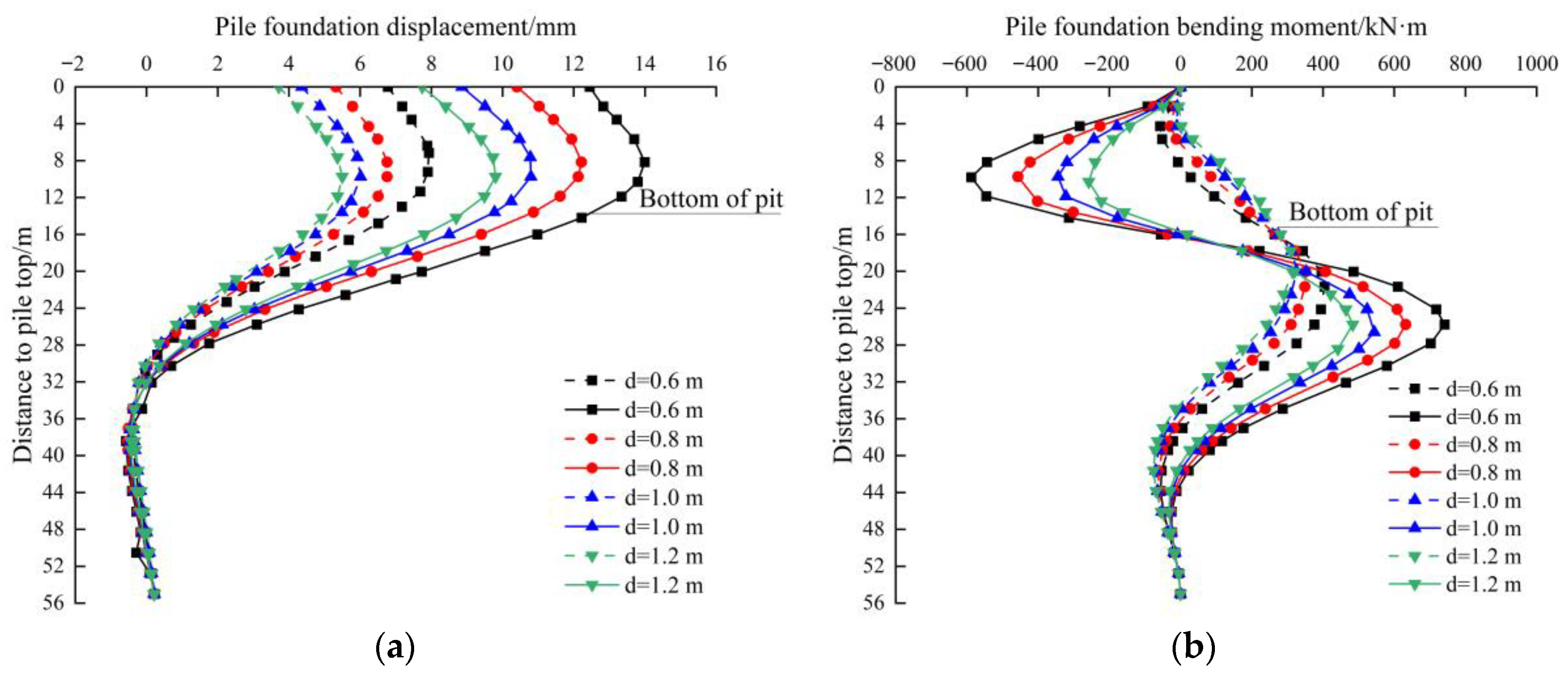
3.3. Analysis of the Effect of the Retaining Wall Rigidity

Since the stiffness of the foundation pit retaining wall is the main factor affecting the deformation of the foundation pit [26], it inevitably affects the displacement and bending moment of the pile foundation. Due to the positive correlation between the bending stiffness of the diaphragm wall and its thickness, we chose to use the four common cases of diaphragm wall thickness d of 0.6 m, 0.8 m, 1.0 m, and 1.2 m, respectively. The remaining variables were the same as in the above numerical model. Since the demolition of partition walls has the most obvious effect on the behavior of pile foundations when the distance between the pile foundation and the partition wall is relatively close, pile foundation #1 is selected for analysis when L = 0 m in the above simulated working condition, and the distribution of displacement and bending moment is shown in Figure 13. In this figure, the displacement of the pile foundation is positive when it moves towards the pit, and the bending moment is positive when the north surface of the pile foundation is pulled.
From Figure 13, it can be seen that in the two working conditions before and after the demolition of the partition wall, the displacement and bending moments of the pile foundation decrease with increasing diaphragm wall thickness. Due to the increased stiffness of the diaphragm wall, the deformation of the wall is reduced, and correspondingly, the displacement and bending moment of the pile foundation are decreased. The demolition of the partition wall resulted in a significant increase in the horizontal displacement and bending moment of the pile foundation. The maximum displacement and upper bending moment values both occur at a distance of 10 m from the top of the pile, and the upper and lower bending moments of the pile body have significantly increased. This is because after the partition wall is demolished, the displacement of the retaining wall towards the pit causes the soil to flow towards the pit, resulting in an additional bending moment on the upper pile body. However, the lower pile end is affected by the displacement of the upper pile body towards the pit, resulting in a trend of displacement away from the pit, which forms a thrust on the soil. Due to the penetration of the elevated pile foundation into the rock layer, a significant reverse bending moment occurred in the lower pile body. The increase and growth rate of the maximum displacement and bending moment values are shown in Table 5. From Table 5, it can be seen that as the thickness of the diaphragm wall is gradually increased, there is a gradual decrease in the increment of the pile displacement and bending moment values after the partition wall is demolished, indicating that increasing the stiffness of the diaphragm wall can effectively reduce the effect of partition wall demolition on adjacent pile foundations.

4. Discussion

Due to the spatial effect at the end of the partition wall, which is similar to the corner of a conventional foundation pit, the pile foundation adjacent to the partition wall is significantly affected by the spatial effect. Before the partition wall is demolished, the displacement and bending moments of piles near the partition wall are smaller than those far away. After the partition wall is demolished, the displacement and bending moment of the pile foundation increase obviously, but the value is still small after the increase, and the increment decreases with the increase in stiffness of the retaining wall.
With the increasing development of underground space, the depth of foundation pit excavation is also increasing. In order to ensure the safety of foundation pits, the application of large-diameter bored piles, mixing piles, and concrete support is increasing, which leads to high energy consumption and high carbon emissions from foundation pit engineering. This is contrary to the goal of sustainable development. For the foundation pit with a partition wall, the spacing effect of the partition wall can be used to achieve the sustainable development goal of energy savings and reducing the effect of excavation on the nearby environment. It is recommended to take measures such as reducing the number of concrete supports, increasing the horizontal spacing of concrete supports, and reducing the thickness of the retaining wall near the partition wall to reduce the stiffness of the support system. When the foundation pit is close to the pile foundation, it is recommended to set the partition wall near the pile foundation to reduce the response of the pile foundation during excavation. If the deformation requirement of the pile foundation is high, the stiffness of the retaining wall at the end of the partition wall can be appropriately increased to further maintain the stability of the pile foundation’s behavior.

5. Conclusions

The focus of this paper was on the effect of the distance from the pile foundation to the partition wall and the stiffness of the retaining wall on the horizontal displacement and bending moment of the adjacent pile foundations during the demolition of the partition wall, and it summarized the law of the difference in response of the front and rear row piles under the partition wall demolition. Based on the excavation project of a long strip foundation pit adjacent to pile foundations in areas of soft soil, monitoring data from the site was used to analyze the effect of partition wall demolition on the retaining wall and the adjacent soil. Finite element software was used to study the effect of the partition walls on the displacement and bending moments of the adjacent pile foundations. The following conclusions can be drawn:
(1) Based on the results of the on-site monitoring, the horizontal displacement and surface settlement of the southern retaining wall of the foundation pit increased by 11% and 12%, respectively, following the demolition of the partition wall, and the values were close to the alarm values. Therefore, the effect of the demolition of the partition walls in the project needs to be considered, especially in situations where there has been substantial deformation before the demolition, and close monitoring of adjacent areas should be carried out during demolition.
(2) The foundation pit partition wall has a strong supporting effect on the retaining wall, rendering the displacement of the retaining wall near the partition wall smaller than that far away. Furthermore, the displacement and bending moments of the pile foundation in the vicinity of the partition wall are correspondingly smaller than those in the far distance, indicating a significant spatial effect at the end of the partition wall. Therefore, the stiffness of the supporting system of the foundation pit near the partition wall can be reduced in the project to realize energy savings and reduce emissions. The demolition of the partition wall will cause the displacement and bending moment of the adjacent pile foundation to increase, but the value after the increase is still small, so it is recommended to set the partition wall in the foundation pit section close to the pile foundation to reduce the adjacent effect of excavation. The effect of demolishing the partition wall on the pile foundation decreases as distance increases, with an effective range of approximately 1.1 times the depth of the foundation pit.
(3) When the distance between the pile foundation and the partition wall is relatively small, there is a significant difference in the behavior response of front row and rear row piles affected by partition wall demolition, manifested as a larger increase in the displacement and bending moment of the piles in the front row of the pile and a smaller increase in rear row pile displacement and bending moment. As the distance increases, the difference in response to partition wall demolition between the front and rear rows of piles gradually diminishes and eventually tends to be consistent.
(4) The effect of partition wall demolition on adjacent pile foundations can be effectively mitigated by increasing the rigidity of the diaphragm wall. As a result of this, When the deformation requirement of the adjacent pile foundation is high, it can be thought of as an appropriate increase in the stiffness of the retaining wall at the end of the partition wall.
Some areas need to be further explored in this study. There are two common methods of demolishing partition walls: demolition after excavation to the bottom of the pit and demolition with the excavation of the pit. For the purposes of this paper, we focus only on the demolition of partition walls after excavation to the bottom of the pit, and future research is needed on the situation where partition walls are demolished with excavation. The project relied on in this article is located in soft soil areas, and the stress state of the rock mass in the project is more complex [27,28]. Further study is needed on the spatial effect of foundation pit partition walls in rock areas and how to adjust the retaining structure to reduce the effect of partition wall demolition [29,30].

Author Contributions

Conceptualization, J.Y.; methodology, J.Y.; validation, N.Z.; investigation, J.Y., and N.Z.; resources, J.Y.; data curation, N.Z.; writing—original draft preparation, N.Z.; writing—review and editing, N.Z.; visualization, N.Z.; supervision, J.Y.; project administration, J.Y.; funding acquisition, J.Y. All authors have read and agreed to the published version of the manuscript.

Funding

This research was funded by the Key Research and Development Program of Zhejiang Province, grant number 2021C01131.

Institutional Review Board Statement

Not applicable.

Informed Consent Statement

Not applicable.

Data Availability Statement

All data included in this study are available upon request by contacting the corresponding author.

Acknowledgments

Thanks are due to Feng Li (Zhejiang University of Science and Technology, Hangzhou) for assistance with the numerical simulation and Zhehao Zhao (Zhejiang University of Science and Technology, Hangzhou) for valuable advice.

Conflicts of Interest

The authors declare that there is no conflict of interest.

References

  1. Hsieh, P.G.; Ou, C.Y.; Shih, C. A simplified plane strain analysis of lateral wall deflection for excavations with cross walls. Can. Geotech. J. 2012, 49, 1134–1146. [Google Scholar] [CrossRef]
  2. Ou, C.Y.; Hsieh, P.G.; Lin, Y.L. Performance of excavations with cross walls. J. Geotech. Geoenviron. Eng. 2011, 137, 94–104. [Google Scholar] [CrossRef]
  3. Wu, S.H.; Ching, J.; Ou, C.Y. Predicting wall displacements for excavations with cross walls in soft clay. J. Geotech. Geoenviron. Eng. 2013, 139, 914–927. [Google Scholar] [CrossRef]
  4. Hsieh, P.G.; Ou, C.Y. Mechanism of buttress walls in restraining the wall deflection caused by deep excavation. Tunn. Undergr. Space Technol. 2018, 82, 542–553. [Google Scholar] [CrossRef]
  5. Hsieh, P.G.; Ou, C.Y. Simplified approach to estimate the maximum wall deflection for deep excavations with cross walls in clay under the undrained condition. Acta Geotech. 2016, 11, 177–189. [Google Scholar] [CrossRef]
  6. Han, M.; Li, Z.; Mei, G.X.; Bao, X.H.; Jia, J.Q.; Liu, L.L.; Li, Y.Y. Characteristics of subway excavation in soft soil and protective effects of partition wall on the historical building and pile foundation building. Bull. Eng. Geol. Environ. 2022, 81, 307. [Google Scholar] [CrossRef]
  7. Li, Z.; Han, M.; Liu, L.L.; Li, Y.Y.; Yan, S.H. Corner and partition wall effects on the settlement of a historical building near a supported subway excavation in soft soil. Comput. Geotech. 2020, 128, 103805. [Google Scholar] [CrossRef]
  8. Wu, T. Influence analysis of partition width of long strip pit on deformation. J. Undergr. Space Eng. 2021, 17, 807–813. [Google Scholar]
  9. Cheng, C.; Likitlersuang, S. Underground excavation behaviour in Bangkok using three-dimensional finite element method. Comput. Geotech. 2018, 95, 68–81. [Google Scholar] [CrossRef]
  10. Ahmadi, A.; Ahmadi, M.M. Three-dimensional numerical analysis of corner effect of an excavation supported by ground anchors. Int. J. Geotech. Eng. 2022, 16, 903–915. [Google Scholar] [CrossRef]
  11. Finno, R.J.; Roboski, J.F. Three-dimensional responses of a tied-back excavation through clay. J. Geotech. Geoenviron. Eng. 2005, 131, 273–282. [Google Scholar] [CrossRef]
  12. Roboski, J.; Finno, R.J. Distributions of ground movements parallel to deep excavations in clay. Can. Geotech. J. 2006, 43, 43–58. [Google Scholar] [CrossRef]
  13. Fuentes, R. Influence of corners in excavations on damage assessment. Geotech. Res. 2019, 6, 91–102. [Google Scholar] [CrossRef] [Green Version]
  14. Szepesházi, A.; Mahler, A.; Móczár, B. Three dimensional finite element analysis of deep excavations’ concave corners. Period Polytech. Civil Eng. 2016, 60, 371–378. [Google Scholar] [CrossRef] [Green Version]
  15. Abbas, Q.; Yoon, J.; Lee, J. Characterization of wall deflection and ground settlement for irregular-shaped excavations with changes in corner configuration. Int. J. Geomech. 2023, 23, 4022258. [Google Scholar] [CrossRef]
  16. Russo, G.; Nicotera, M.V. A closed form shape function describing 3D settlement field around a deep excavation in sand. Sci. Rep. 2022, 12, 18528. [Google Scholar] [CrossRef] [PubMed]
  17. Wang, C.; Wang, X. A quantitative analysis of the spatial effects of retaining structure for slender foundation pits. IOP Conf. Ser. Earth Environ. Sci. 2018, 189, 022036. [Google Scholar] [CrossRef] [Green Version]
  18. Li, Y.; Wang, C.X.; Sun, Y.; Wang, R.C.; Shao, G.J.; Yu, J. Analysis of corner effect of diaphragm wall of special-shaped foundation pit in complex stratum. Front. Earth Sci. 2022, 10, 794756. [Google Scholar] [CrossRef]
  19. Tan, J.; Zheng, X.Y.; Sun, Y.; Shao, G.J.; Chen, Y.B. Analysis of pit corner effect of special-shaped foundation pit of subway station. IOP Conf. Ser. Earth Environ. Sci. 2020, 558, 032032. [Google Scholar] [CrossRef]
  20. Liu, L.; Wu, R.; Congress, S.S.C.; Du, Q.; Cai, G.; Li, Z. Design optimization of the soil nail wall-retaining pile-anchor cable supporting system in a large-scale deep foundation pit. Acta Geotech. 2021, 16, 2251–2274. [Google Scholar] [CrossRef]
  21. Wu, B.; Peng, Y.Y.; Meng, G.W.; Pu, S.Q. Field measurement and analysis of time and space effects of excavation construction of connected deep foundation pits in Ningbo soft soil area. J. Railw. Sci. Eng. 2020, 17, 82–94. [Google Scholar]
  22. Liu, X.R.; Wang, L.F.; Chen, F.; Yuan, X.F.; Lin, G.Y. Research on deformation characteristics and parameter optimization of inner braced ground wall. J. Undergr. Space Eng. 2021, 17, 727–738. [Google Scholar]
  23. Jia, M.; Yang, X.H.; Ye, J.Z. Corner effect of active earth pressure for small-sized excavation. J. Harbin Inst. Technol. 2016, 48, 95–102. [Google Scholar]
  24. Lou, C.H.; Xia, T.D.; Liu, N.W. Spatial effect analysis of the impact of foundation pits on the surrounding environment in soft soil areas. Chin. J. Geotech. Eng. 2019, 41, 249–252. [Google Scholar]
  25. Li, L.X.; Zhang, Y.J.; Hu, X.B. Analysis of excavation impact of a pit-in-pit based on PLAXIS 3D finite element software. J. Undergr. Space Eng. 2016, 12, 254–261, 266. [Google Scholar]
  26. Wang, S.R.; Li, Y.; Li, Z.F. Experimental on squeezed pan piles in single and double rows under loading for protecting foundation excavation. J. China Coal Soc. 2009, 34, 537–541. [Google Scholar]
  27. Wang, S.; Li, D.; Li, C.; Zhang, C.; Zhang, Y. Thermal radiation characteristics of stress evolution of a circular tunnel excavation under different confining pressures. Tunn. Undergr. Space Technol. 2018, 78, 76–83. [Google Scholar] [CrossRef]
  28. Sun, X.M.; He, M.C.; Liu, C.Y.; Gu, J.C.; Wang, S.R.; Ming, Z.Q.; Jing, H.H. Development of nonlinear triaxial mechanical experiment system for soft rock specimen. Chin. J. Rock Mech. Eng. 2005, 24, 2870–2874. [Google Scholar]
  29. Xu, C.; Li, Z.; Wang, S.; Wang, S.; Fu, L.; Tang, C. Pullout performances of grouted rockbolt systems with bond defects. Rock Mech. Rock Eng. 2018, 51, 861–871. [Google Scholar] [CrossRef]
  30. Wang, S.; Xiao, H.; Hagan, P.; Zou, Z. Mechanical behavior of fully-grouted bolt in jointed rocks subjected to double shear tests. Dynamic 2017, 92, 314–320. [Google Scholar]
Figure 1. Plane relationship of foundation pit.
Sustainability 15 10409 g001
Figure 2. Horizontal displacement of Q2.
Sustainability 15 10409 g002
Figure 3. Distribution of surface settlement. (a) D1 survey line; (b) D2 survey line.
Sustainability 15 10409 g003
Figure 4. Surface settlement fitting curve. (a) D1 survey line fitting curve; (b) D2 survey line fitting curve.
Sustainability 15 10409 g004
Figure 5. 3D finite element model.
Sustainability 15 10409 g005
Figure 6. Horizontal displacement cloud chart of the diaphragm wall. (a) Before demolition of partition wall; (b) After demolition of partition wall.
Sustainability 15 10409 g006
Figure 7. Comparison of simulated and measured values of Q2. (a) Before demolition of partition wall; (b) After demolition of partition wall.
Sustainability 15 10409 g007
Figure 8. Comparison of simulated and measured values of D2. (a) Before demolition of partition wall; (b) After demolition of partition wall.
Sustainability 15 10409 g008
Figure 9. Horizontal displacement and a bending moment of plie1. (a) Horizontal displacement distribution; (b) Bending moment distribution.
Sustainability 15 10409 g009
Figure 10. The relationship between the maximum displacement value and distance to the partition wall of pile 1.
Sustainability 15 10409 g010
Figure 11. The relationship between the maximum displacement growth rate and distance to the partition wall of pile 1.
Sustainability 15 10409 g011
Figure 12. Curve of maximum displacement and bending moment values of the front and rear row pile foundations. (a) Maximum displacement increment; (b) Maximum bending moment increment.
Sustainability 15 10409 g012
Figure 13. Horizontal displacement and bending moment of pile 1 with different wall thicknesses. (a) Displacement distribution; (b) Bending moment distribution.
Sustainability 15 10409 g013
Table 1. Working condition division.
Working Condition No.Construction Content
WC 1Excavate the first layer of soil up to the crown beam and concrete support bottom.
WC 2Excavate the second layer of soil to the bottom of the second steel support.
WC 3Excavate the third layer of soil to the bottom of the third concrete support layer.
WC 4Excavate soil to the bottom of the foundation pit.
WC 5Demolish the partition wall.
Table 2. Computational procedure.
Simulation StepsSimulation Content
Step 1Initial crustal stress equilibrium.
Step 2Construction of the diaphragm and partition wall.
Step 3Excavate the first layer of soil in the western area and apply the first support.
Step 4Excavate the second layer of soil in the western area and apply for the second support.
Step 5Excavate the third layer of soil in the western area and apply the third support.
Step 6Excavation to the bottom of the pit in the western area.
Step 7Excavate the first layer of soil in the eastern area and apply the first support.
Step 8Excavate the second layer of soil in the eastern area and apply the second support.
Step 9Excavate the third layer of earthwork in the eastern area and apply the third support.
Step 10Excavation to the bottom of the pit in the eastern area.
Step 11Demolish the partition wall.
Table 3. Soil layer calculation parameters.
Soil LayerLayer Thickness
H/m
Bulk Density
γ/(Kn·m−3)
Cohesive Force
c/kPa
Internal Friction Angle φ/(°)Elastic Modulus
E/MPa
Poisson’s Ratio µ
Plain fill soil1.218.211.910.14.50.30
Muddy clay12.116.510.211.94.20.30
Silty clay11.317.431.920.04.10.30
Clay8.221.835.127.921.30.30
Round gravel6.125.25.042.068.30.28
Moderately weathered sandstone46.126.17.542.6432.00.27
Table 4. Structural calculation parameters.
Structure NameElement SelectionElastic Modulus E/MPaBulk Density
γ/(kN·m−3)
Poisson’s Ratio
µ
Diaphragm wallPlate element30.0 × 103250.25
Concrete supportBeam element25.0 × 103230.20
Concrete waste beamBeam element25.0 × 103230.20
Concrete link beamBeam element25.0 × 103230.20
Steel supportBeam element210.0 × 103770.30
Steel waist beamBeam element210.0 × 103770.30
Steel link beamBeam element210.0 × 103770.30
Table 5. Response of pile1 displacement and bending moment caused by the demolition of partition walls with different wall thicknesses.
Thickness/mDisplacementBending Moment
Before Demolition of the Partition Wall/mmAfter Demolition of the Partition Wall/mmIncrement Value
/mm
Growth Rate/%Before Demolition of the Partition Wall
/kN·m
After Demolition of the Partition Wall
/kN·m
Increment Value
/kN·m
Growth Rate/%
0.67.9313.996.0676.39404.07741.46337.3983.5
0.86.7512.215.4680.74351.57632.19280.6279.82
1.06.0110.794.7879.52326.68543.93217.2566.5
1.25.59.84.378.27314.3483.73169.4353.91
Disclaimer/Publisher’s Note: The statements, opinions and data contained in all publications are solely those of the individual author(s) and contributor(s) and not of MDPI and/or the editor(s). MDPI and/or the editor(s) disclaim responsibility for any injury to people or property resulting from any ideas, methods, instructions or products referred to in the content.

