
Investigation into Occurrence Mechanism of Rock Burst Induced by Water Drainage in Deep Mines

 ,
,
Abstract
:1. Introduction
2. Engineering Background
2.1. Field Conditions of LW22106
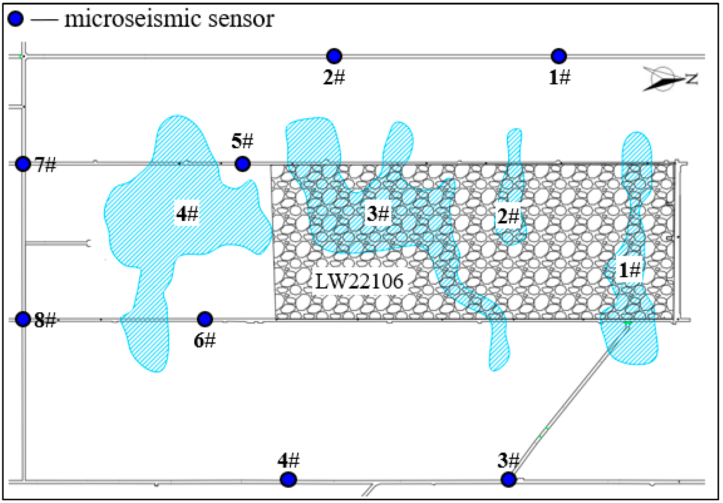
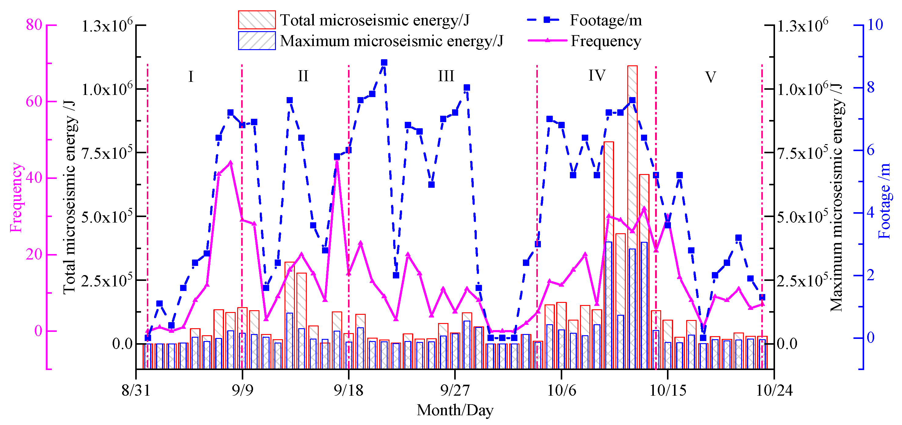
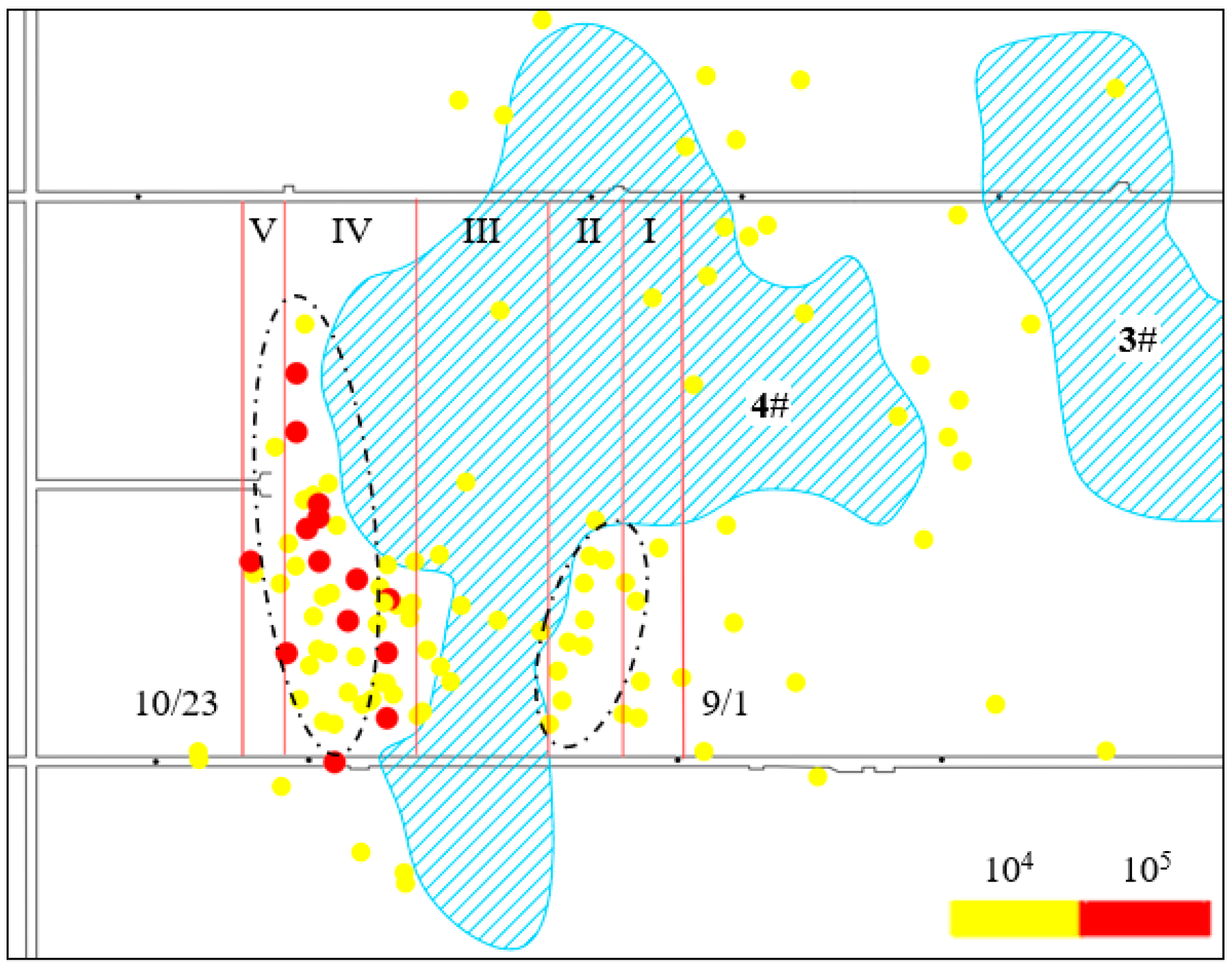
2.2. Description of Mine Seismicity on the Working Face
3. Mechanism of Rock Burst Induced by Roof Water Drainage
3.1. Principle of Effective Stress
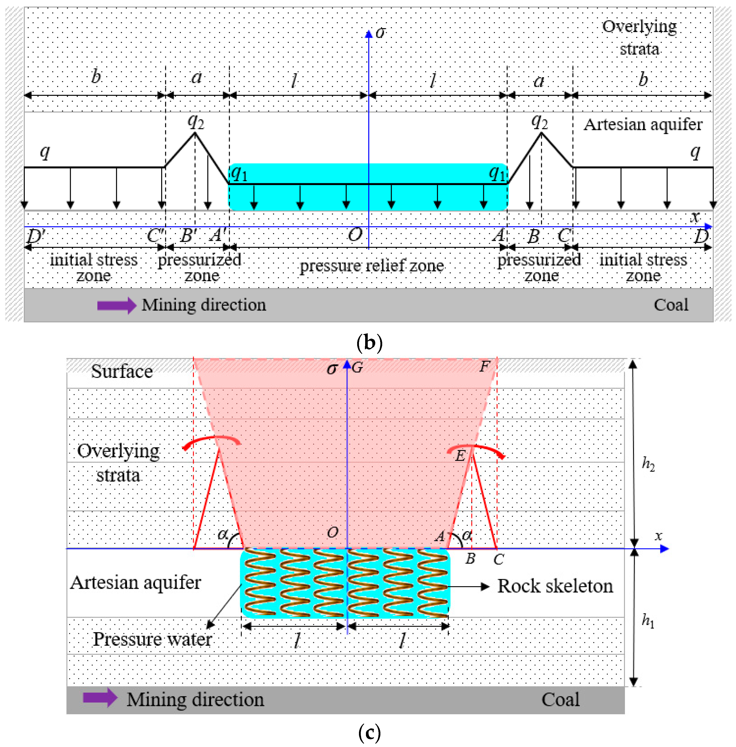
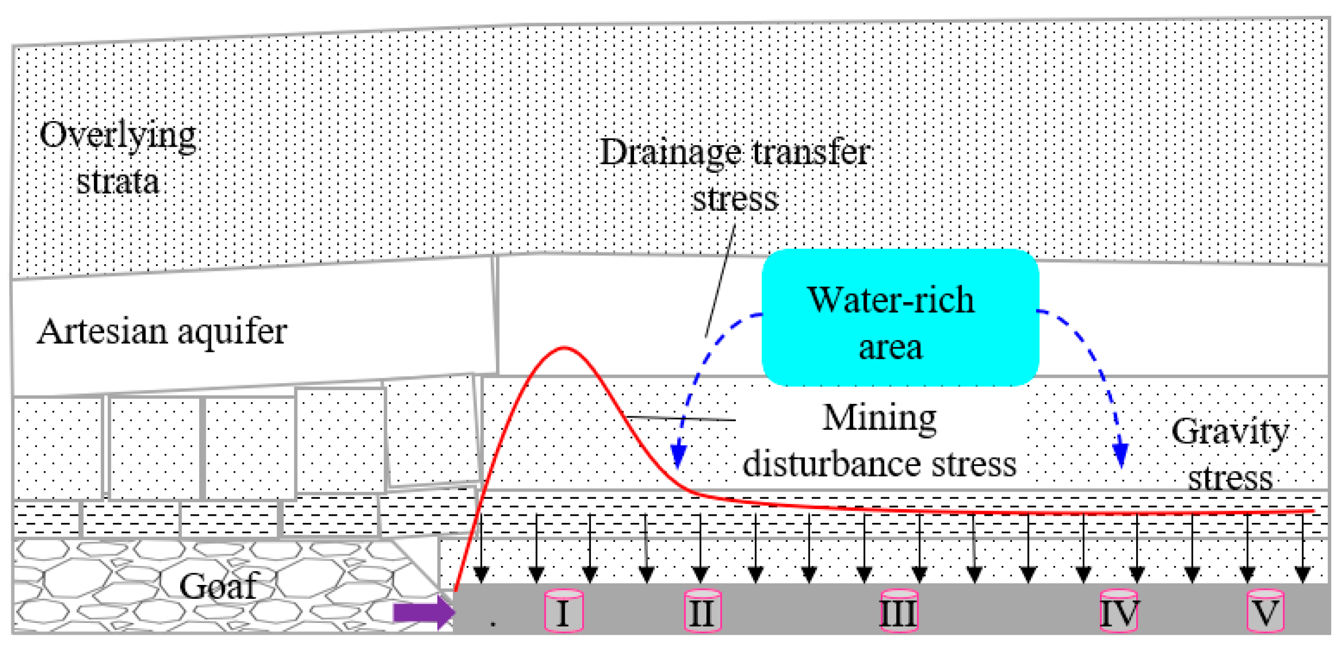
3.2. Stress Migration Law in the Process of Drainage
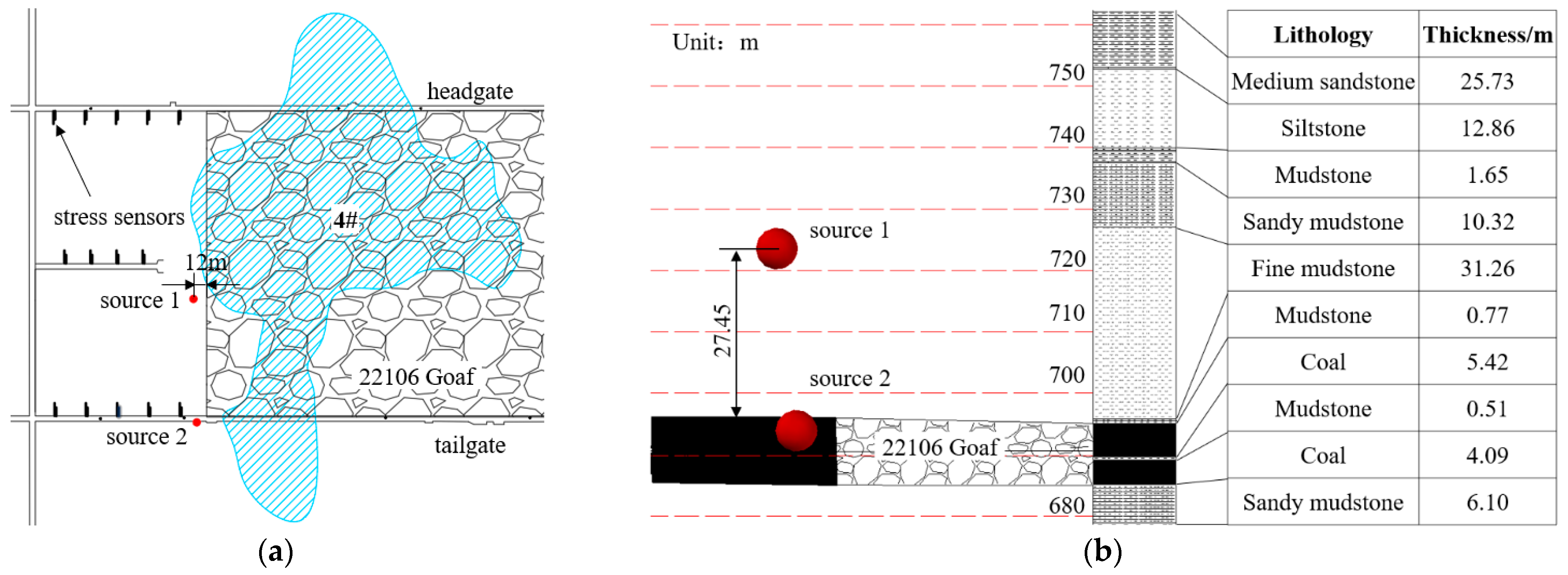
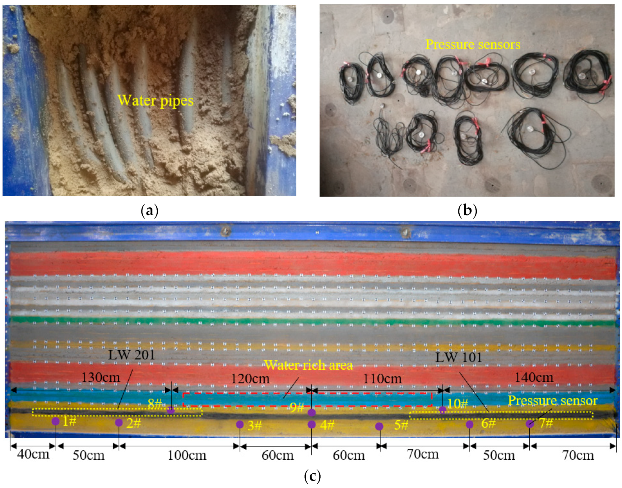
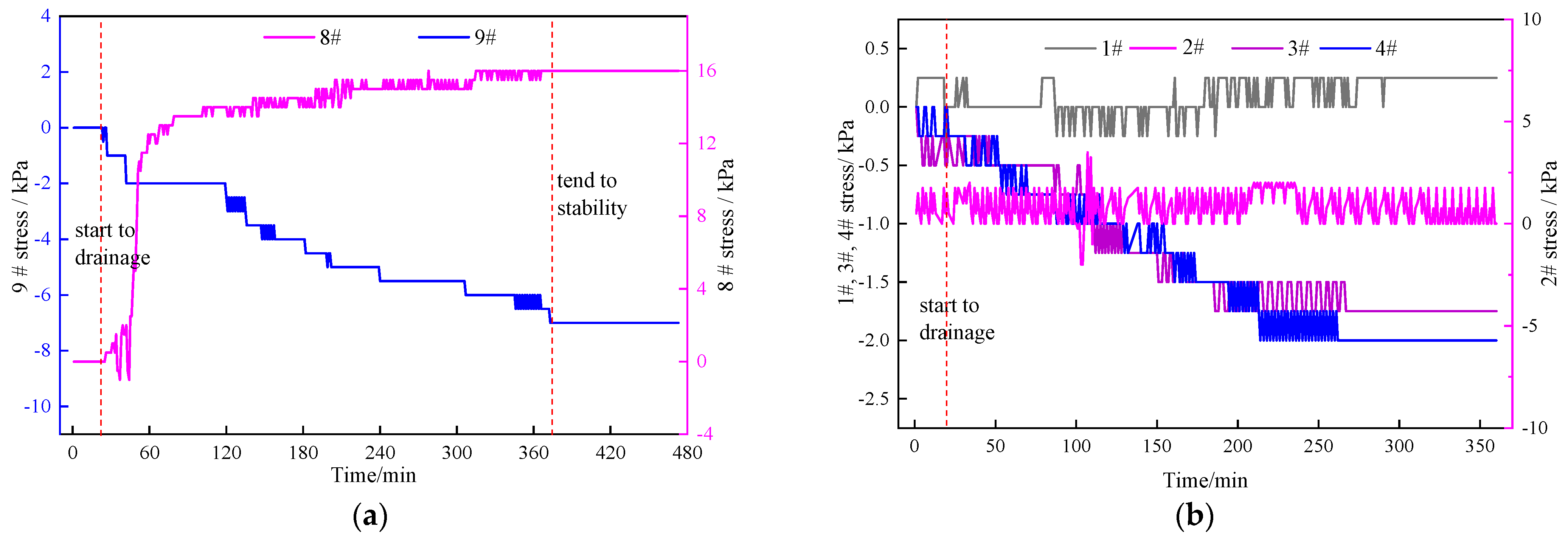
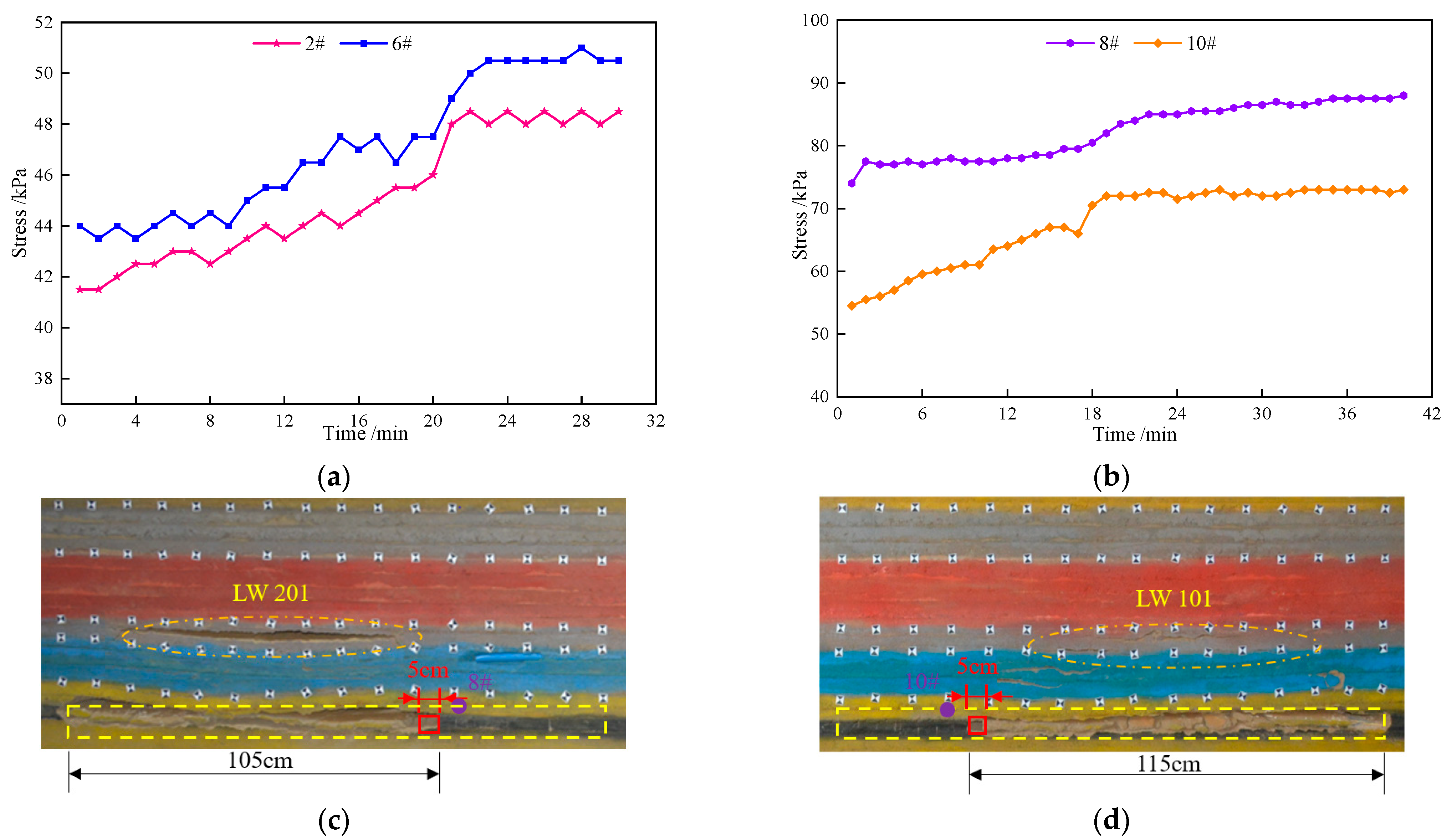
3.3. Physical Simulation Verification
3.4. Analysis of the Relationship between Drainage and Rock Burst
4. Field Application and Verification
4.1. Field Application
4.2. Field Verification
5. Conclusions
Author Contributions
Funding
Institutional Review Board Statement
Informed Consent Statement
Data Availability Statement
Acknowledgments
Conflicts of Interest
References
- Xie, H.P.; Ju, Y.; Ren, S.H.; Gao, F.; Liu, J.Z.; Zhu, Y. Theoretical and technological exploration of deep in situ fluidized coal mining. Front. Energy 2019, 13, 603–611. [Google Scholar] [CrossRef]
- Jiang, Y.D.; Pan, Y.S.; Jiang, F.X.; Dou, L.M.; Ju, Y. State of the art review on mechanism and prevention of coal bumps in China. J. China Coal Soc. 2014, 39, 205–213. [Google Scholar]
- Pan, Y.S. Disturbance response instability theory of rockburst in coal mine. J. China Coal Soc. 2018, 43, 2091–2098. [Google Scholar]
- Li, J.Z.; Li, S.Y.; Ren, W.T.; Liu, H.; Liu, S.; Yan, K.X. Seismic reduction mechanism and engineering application of paste backfilling mining in deep rock burst mines. Sustainability 2023, 15, 4336. [Google Scholar] [CrossRef]
- Qi, Q.X.; Wang, S.G.; Li, H.T.; Mu, P.Y.; Du, W.S.; Yang, G.Y. Stress flow theory for coal bump and its numerical implementation. J. China Coal Soc. 2022, 47, 172–179. [Google Scholar]
- He, M.C.; Zhao, F.; Cai, M.; Du, S. A novel experimental technique to simulate pillar burst in laboratory. Rock Mech. Rock Eng. 2015, 48, 1833–1848. [Google Scholar] [CrossRef]
- Bräuner, G. Rockbursts in Coal Mines and Their Prevention; Routledge: Abingdon, UK, 2017. [Google Scholar]
- Gu, S.T.; Chen, H.X.; Li, W.S.; Jiang, B.Y.; Chen, X. Study on occurrence mechanism and prevention technology of rock burst in narrow coal pillar working face under large mining depth. Sustainability 2022, 14, 15435. [Google Scholar] [CrossRef]
- Das, A.J.; Mandal, P.K.; Paul, P.S.; Sinha, R.K. Generalised Analytical Models for the Strength of the Inclined as well as the Flat Coal Pillars using Rock Mass Failure Criterion. Rock Mech. Rock Eng. 2019, 52, 3921–3946. [Google Scholar] [CrossRef]
- Gao, R.; Kuang, T.J.; Zhang, Y.Q.; Zhang, W.Y.; Quan, C.Y. Controlling mine pressure by subjecting high-level hard rock strata to ground fracturing. Int. J. Coal Sci. Technol. 2021, 8, 1336–1350. [Google Scholar] [CrossRef]
- Vizintin, G.; Kocjancic, M.; Vulic, M. Study of coal burst source locations in the velenje colliery. Energies 2016, 9, 507. [Google Scholar] [CrossRef]
- Dong, S.N.; Ji, Y.D.; Wang, H.; Zhao, B.F.; Cao, H.D.; Liu, Y.; Liu, Y.F.; Ji, Z.K.; Liu, B.G. Prevention and control technology and application of roof water disaster in Jurassic coal field of Ordos Basin. J. China Coal Soc. 2020, 45, 2367–2375. [Google Scholar]
- Dong, S.N.; Wang, H.; Guo, X.M.; Zhou, Z.F. Characteristics of water hazards in China’s coal mines: A review. Mine Water Environ. 2021, 40, 325–333. [Google Scholar] [CrossRef]
- Wang, B.; Jiang, F.X.; Zhu, S.T.; Zhang, X.F.; Shang, X.G.; Gu, Y.S.; Wu, Z. Investigating on the mechanism and prevention of rock burst induced by high intensity mining of drainage area in deep mines. J. China Coal Soc. 2020, 45, 3054–3064. [Google Scholar]
- Jiang, Y.D.; Wang, H.W.; Xue, S.; Zhao, Y.X.; Zhu, J.; Pang, X.F. Assessment and mitigation of coal bump risk during extraction of an island longwall panel. Int. J. Coal Geol. 2012, 95, 20–33. [Google Scholar] [CrossRef]
- Dou, L.M.; He, J.; Cao, A.Y.; Gong, S.Y.; Cai, W. Rock burst prevention methods based on theory of dynamic and static combined load induced in coal mine. J. China Coal Soc. 2015, 40, 1469–1476. [Google Scholar]
- Dou, L.M.; Cai, W.; Cao, A.Y.; Guo, W.H. Comprehensive early warning of rock burst utilizing microseismic multi-parameter indices. Int. J. Rock Mech. Min. Sci. 2018, 28, 767–774. [Google Scholar] [CrossRef]
- Cai, W.; Dou, L.M.; Si, G.Y.; Hu, Y.W. Fault-Induced coal burst mechanism under mining-induced static and dynamic stresses. Engineering 2021, 7, 687–700. [Google Scholar] [CrossRef]
- Qi, Q.X.; Pan, Y.S.; Li, H.T.; Jiang, D.Y.; Shu, L.Y.; Zhao, S.K.; Zhang, Y.J.; Pan, J.F.; Li, H.Y.; Pan, P.Z. Theoretical basis and key technology of prevention and control of coal-rock dynamic disasters in deep coal mining. J. China Coal Soc. 2020, 45, 1567–1584. [Google Scholar]
- Jiang, F.X.; Liu, Y.; Zhang, Y.C.; Wen, J.L.; Yang, W.L.; An, J. A three-zone structure loading model of overlying strata and its application on rockburst prevention. Chin. J. Rock Mech. Eng. 2016, 35, 2398–2408. [Google Scholar]
- Zhu, S.T.; Feng, Y.; Jiang, F.X. Determination of abutment pressure in coal mines with extremely thick alluvium stratum: A typical kind of rock burst mines in china. Rock Mech. Rock Eng. 2016, 49, 1943–1952. [Google Scholar] [CrossRef]
- Zhu, S.T.; Feng, Y.; Jiang, F.X.; Liu, J.H. Mechanism and risk assessment of overall-instability-induced rockbursts in deep island longwall panels. Int. J. Rock Mech. Min. Sci. 2018, 106, 342–349. [Google Scholar] [CrossRef]
- Zhao, Y.X.; Zhou, J.L.; Liu, W.G. Characteristics of ground pressure and mechanism of coal burst in the gob side roadway at Xinjie deep mining area. J. China Coal Soc. 2020, 45, 1595–1606. [Google Scholar]
- Cao, A.Y.; Dou, L.M.; Wang, C.B.; Yao, X.X.; Dong, J.Y.; Gu, Y. Microseismic precursory characteristics of rock burst hazard in mining areas near a large residual coal pillar: A case study from Xuzhuang coal mine, Xuzhou, China. Rock Mech. Rock Eng. 2016, 49, 4407–4422. [Google Scholar] [CrossRef]
- Cao, A.Y.; Dou, L.M.; Cai, W.; Gong, S.Y.; Liu, S.; Jing, G.C. Case study of seismic hazard assessment in underground coal mining using passive tomography. Int. J. Rock Mech. Min Sci. 2015, 78, 1–9. [Google Scholar] [CrossRef]
- Cao, A.Y.; Liu, Y.Q.; Chen, F.; Hao, Q.; Yang, X.; Wang, C.B.; Bai, X.X. Focal mechanism and source parameters analysis of mining-induced earthquakes based on relative moment tensor inversion. Int. J. Environ. Res. Public Health 2022, 19, 7352. [Google Scholar] [CrossRef]
- Gong, F.Q.; Zhang, P.L.; Luo, S.; Li, J.C.; Huang, D. Theoretical damage characterisation and damage evolution process of intact rocks based on linear energy dissipation law under uniaxial compression. Int. J. Rock Mech. Min. Sci. 2021, 146, 104858. [Google Scholar] [CrossRef]
- Gong, F.Q.; Zhong, W.H.; Gao, M.Z.; Si, X.F.; Wu, W.X. Dynamic characteristics of high stressed red sandstone subjected to unloading and impact loads. J. Cent. South Univ. 2022, 29, 596–610. [Google Scholar] [CrossRef]
- Zhao, T.B.; Guo, W.Y.; Han, F.; Gu, S.T. Analysis on energy accumulation and release of roof under influence of mining speed. Coal Sci. Technol. 2018, 46, 37–44. [Google Scholar]
- Huang, B.X.; Liu, J.W. The effect of loading rate on the behavior of samples composed of coal and rock. Int. J. Rock Mech. Min. Sci. 2013, 61, 23–30. [Google Scholar] [CrossRef]
- Cui, F.; Zhang, T.H.; Lai, X.P.; Wang, S.J.; Chen, J.Q.; Qian, D.Y. Mining disturbance characteristics and productivity of rock burst mines under different mining intensities. J. China Coal Soc. 2021, 46, 3781–3793. [Google Scholar]
- Feng, L.F.; Dou, L.M.; Wang, X.D.; Jin, D.W.; Cai, W.; Xu, G.G.; Jiao, B. Mechanism of mining advance speed on energy release from hard roof movement. J. China Coal Soc. 2019, 44, 3329–3339. [Google Scholar]
- Zhou, K.Y.; Dou, L.M.; Song, S.K.; Ma, X.T.; Chen, B.G. Experimental Study on the mechanical behavior of coal samples during water saturation. ACS Omega 2021, 6, 33822–33836. [Google Scholar] [CrossRef]
- Zheng, L.W.; Dong, S.N.; Tang, S.L.; Ji, Y.D.; Luo, J.Z.; Li, H.H.; Li, X.L.; Liu, C.Y.; Zeng, M.L. Molecular structure characterization of coal under the water-rock interaction in acid mine drainage (AMD). J. Mol. Struct. 2022, 1251, 132043. [Google Scholar]
- Zhang, C.; Bai, Q.S.; Han, P.H.; Wang, L.; Wang, X.J.; Wang, F.T. Strength weakening and its micromechanism in water-rock interaction, a short review in laboratory tests. Int. J. Coal Sci. Technol. 2023, 10, 10. [Google Scholar] [CrossRef]
- Han, P.H.; Zhang, C.; Wang, X.J.; Wang, L. Study of mechanical characteristics and damage mechanism of sandstone under long-term immersion. Eng. Geol. 2023, 315, 107020. [Google Scholar] [CrossRef]
- Zhang, C.; Bai, Q.S.; Han, P.H. A review of water rock interaction in underground coal mining: Problems and analysis. Bull. Eng. Geol. Environ. 2023, 82, 157. [Google Scholar]
- Cao, A.Y.; Chen, F.; Liu, Y.Q.; Dou, L.M.; Wang, C.B.; Yang, X.; Bai, X.X.; Song, S.K. Response characteristics of rupture mechanism and source parameters of mining tremors in frequent coal burst area. J. China Coal Soc. 2022, 47, 722–733. [Google Scholar]
- Li, D.; Jiang, F.X.; Chen, Y.; Shu, C.X.; Tian, Z.J.; Wang, Y.; Wang, W.B. Mechanism of rockburst induced by “dynamic-static”stress effect in water-rich working face of deep well. Chin. J. Geo. Eng. 2018, 40, 1714–1722. [Google Scholar]
- Du, X.L.; Zhang, P.; Xu, C.S.; Lu, D.C. On principle of effective stress and effective stress. Chin. J. Geo Eng. 2018, 40, 486–494. [Google Scholar]
- Li, Z.; Yu, S.C.; Zhu, W.B.; Feng, G.R.; Xu, J.M.; Guo, Y.X.; Qi, T.Y. Dynamic loading induced by the instability of voussoir beam structure during mining below the slope. Int. J. Rock Mech. Min. Sci. 2020, 132, 104343. [Google Scholar]
- Wang, J.C.; Jiang, F.X.; Meng, X.J.; Wang, X.Y.; Zhu, S.T.; Feng, Y. Mechanism of rock burst occurrence in specially thick coal seam with rock parting. Rock Mech. Rock Eng. 2016, 49, 1953–1965. [Google Scholar] [CrossRef]
- Hosseini, N. Evaluation of the rock burst potential in longwall coal mining using passive seismic velocity tomography and image subtraction technique. J. Seismol. 2017, 21, 1101–1110. [Google Scholar] [CrossRef]


| Serial Number | Lithology | Thickness/ cm | Total Thickness/cm | Similar Materials/kg | |||
|---|---|---|---|---|---|---|---|
| Sand | CaCO3 | Gypsum | Water | ||||
| 26 | Sandy mudstone | 5 | 158 | 85.23 | 2.56 | 5.97 | 9.38 |
| 25 | Fine sandstone | 4 | 153 | 66.67 | 5.00 | 3.33 | 7.50 |
| 24 | Sandy mudstone | 5 | 149 | 85.23 | 2.56 | 5.97 | 9.38 |
| 23 | Fine sandstone | 4 | 144 | 66.67 | 5.00 | 3.33 | 7.50 |
| 22 | Siltstone | 19 | 140 | 316.67 | 27.71 | 11.88 | 35.63 |
| 21 | Fine mudstone | 5 | 121 | 83.33 | 6.25 | 4.17 | 9.38 |
| 20 | Medium sandstone | 4 | 116 | 65.63 | 5.63 | 3.75 | 7.50 |
| 19 | Sandy mudstone | 5 | 112 | 85.23 | 2.56 | 5.97 | 9.38 |
| 18 | Medium sandstone | 3 | 107 | 49.22 | 4.22 | 2.81 | 5.63 |
| 17 | Sandy mudstone | 4 | 104 | 68.18 | 2.05 | 4.77 | 7.50 |
| 16 | Medium sandstone | 2 | 100 | 32.81 | 2.81 | 1.88 | 3.75 |
| 15 | Sandy mudstone | 5 | 98 | 85.23 | 2.56 | 5.97 | 9.38 |
| 14 | Medium sandstone | 5 | 93 | 82.03 | 7.03 | 4.69 | 9.38 |
| 13 | Sandy mudstone | 5 | 88 | 85.23 | 2.56 | 5.97 | 9.38 |
| 12 | Fine sandstone | 5 | 83 | 83.33 | 6.25 | 4.17 | 9.38 |
| 11 | Sandy mudstone | 16 | 78 | 272.73 | 8.18 | 19.09 | 30.00 |
| 10 | Siltstone | 4 | 62 | 66.67 | 5.83 | 2.50 | 7.50 |
| 9 | Sandy mudstone | 12 | 58 | 204.55 | 6.14 | 14.32 | 22.50 |
| 8 | Fine sandstone | 4 | 46 | 66.67 | 5.00 | 3.33 | 7.50 |
| 7 | Siltstone | 13 | 42 | 216.67 | 18.96 | 8.13 | 24.38 |
| 6 | Medium sandstone | 1 | 29 | 16.41 | 1.41 | 0.94 | 1.88 |
| 5 | Sandy mudstone | 4 | 28 | 68.18 | 2.05 | 4.77 | 7.50 |
| 4 | Medium sandstone | 10 | 24 | 164.06 | 14.06 | 9.38 | 18.75 |
| 3 | Siltstone | 6 | 14 | 105.00 | 7.88 | 18.38 | 13.13 |
| 2 | 2-2 Coal | 5 | 8 | 48.21 | 5.63 | 2.41 | 5.63 |
| 1 | Sandy mudstone | 3 | 3 | 233.33 | 20.42 | 8.75 | 26.25 |
| Total | 2803.14 | 180.27 | 166.59 | 315.00 | |||
| Ic | <1.5 | 1.5~2.0 | 2.0~2.5 | >2.5 |
|---|---|---|---|---|
| Rock burst risk | None | Weak | Medium | Powerful |
| Location | Serial Number | Range/m | Main Factors | Risk Degree of Rock Burst | |
|---|---|---|---|---|---|
| Headgate | 1 | Distance from open-off cut | 740~1100 | Depth, mining disturbance | Weak |
| Tailgate | 2 | 740~830 | Depth, mining disturbance | Weak | |
| 3 | 830~930 | Depth, mining disturbance, bifurcation of coal | Medium | ||
| 4 | 930~1100 | Depth, mining disturbance | Weak | ||
| Location | Serial Number | Range/m | Main Factors | Risk Degree of Rock Burst | |
|---|---|---|---|---|---|
| Headgate | 1 | Distance from open-off cut | 740~780 | Depth, mining disturbance | Weak |
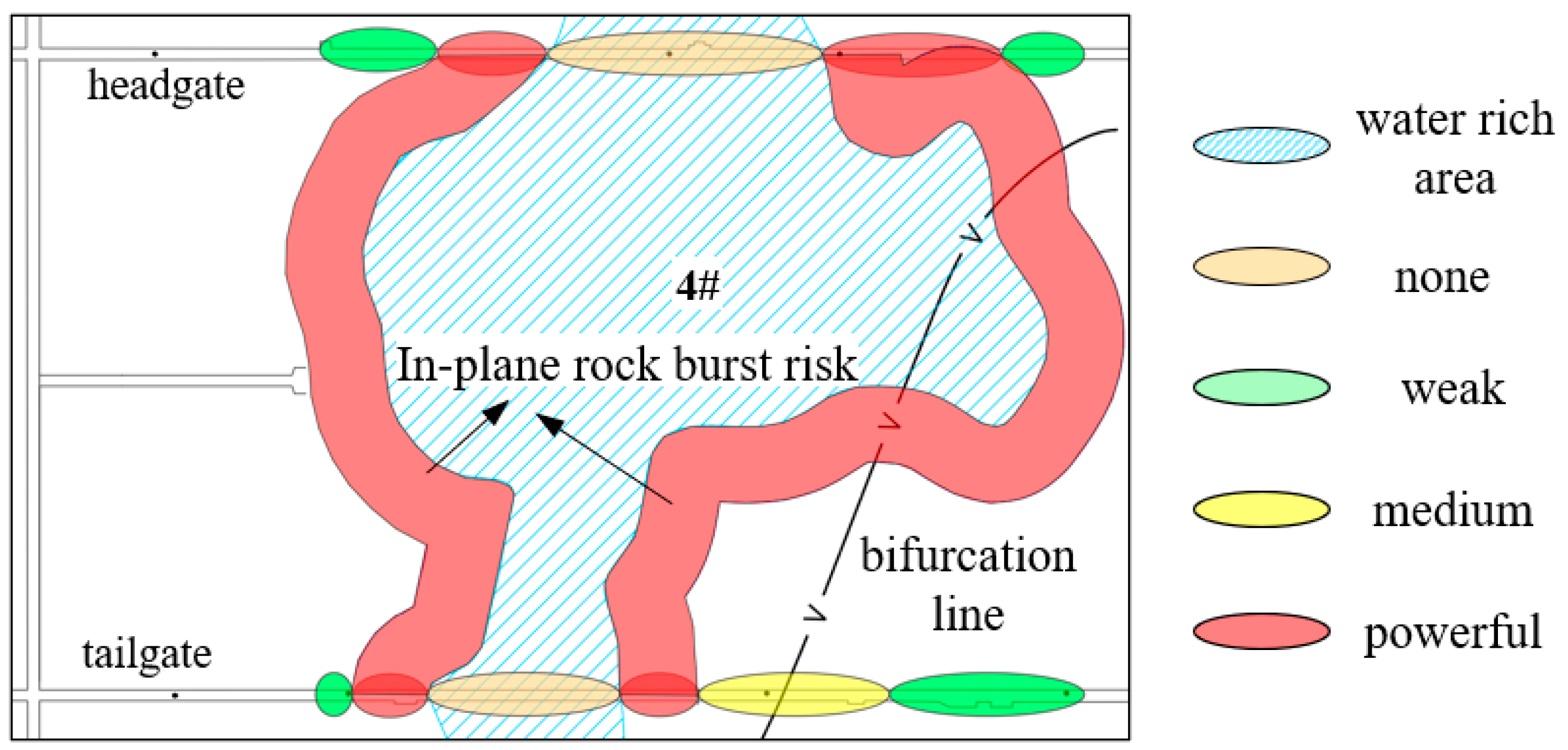
| 2 | 780~862 | Depth, mining disturbance drainage pressurization | Powerful | ||
| 3 | 862~988 | Depth, mining disturbance drainage pressure relief | None | ||
| 4 | 988~1038 | Depth, mining disturbance drainage pressurization | Powerful | ||
| 5 | 1038~1100 | Depth, mining disturbance | Weak | ||
| Tailgate | 6 | Distance from open-off cut | 740~830 | Depth, mining disturbance | Weak |
| 7 | 830~918 | Depth, mining disturbance Bifurcation of coal | Medium | ||
| 8 | 918~953 | Depth, mining disturbance bifurcation of coal, drainage pressurization | Powerful | ||
| 9 | 953~1043 | Depth, mining disturbance drainage pressure relief | None | ||
| 10 | 1043~1078 | Depth, mining disturbance drainage pressurization | Powerful | ||
| 11 | 1078~1100 | Depth, mining disturbance | Weak | ||
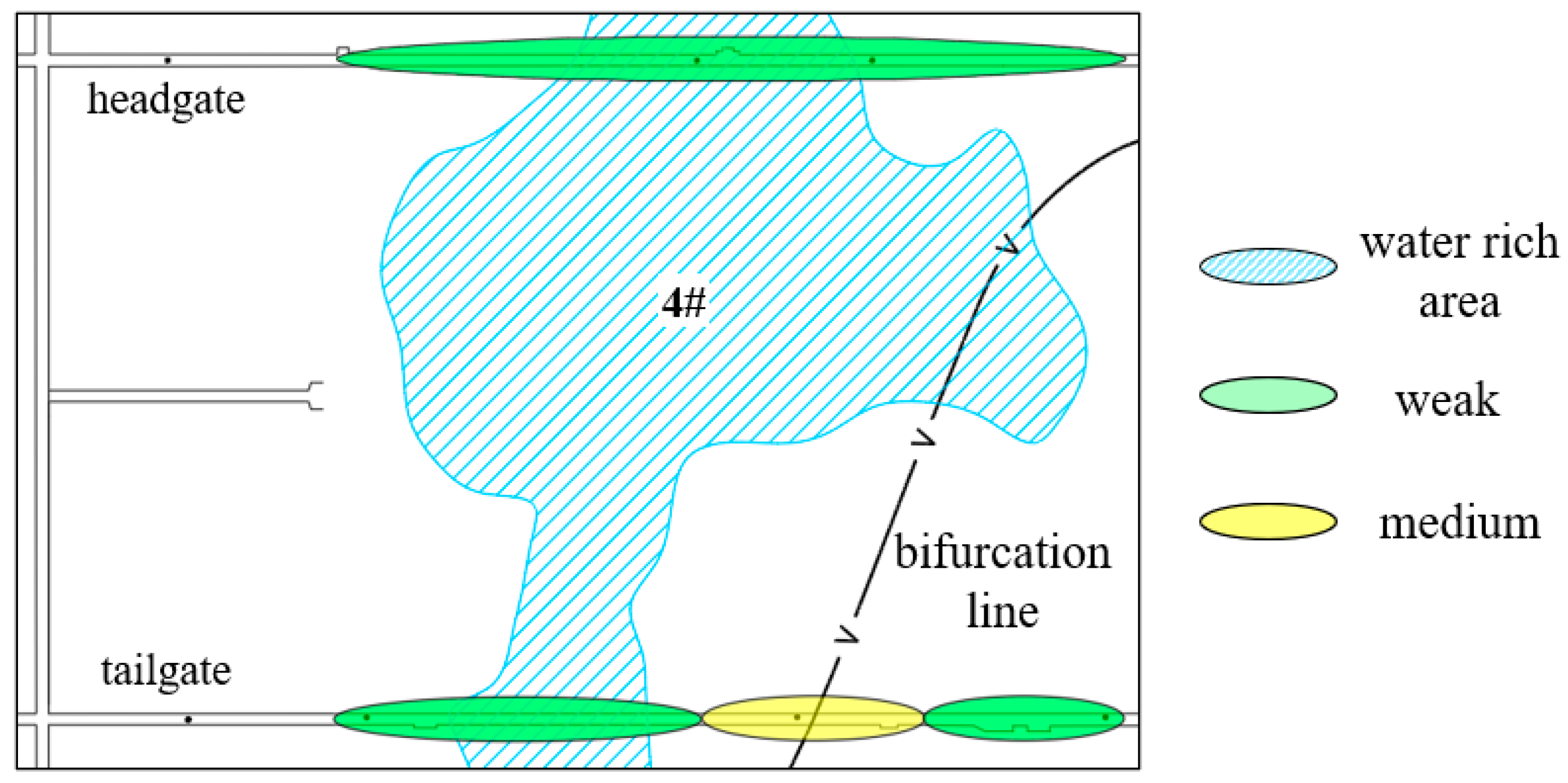
| In-plane | 12 | no. 4 water rich area | Right side 0~35 | Depth, mining disturbance drainage pressurization | Powerful |
| 13 | Left side 0~35 | Depth, mining disturbance drainage pressurization | Powerful | ||
Disclaimer/Publisher’s Note: The statements, opinions and data contained in all publications are solely those of the individual author(s) and contributor(s) and not of MDPI and/or the editor(s). MDPI and/or the editor(s) disclaim responsibility for any injury to people or property resulting from any ideas, methods, instructions or products referred to in the content. |
© 2023 by the authors. Licensee MDPI, Basel, Switzerland. This article is an open access article distributed under the terms and conditions of the Creative Commons Attribution (CC BY) license (https://creativecommons.org/licenses/by/4.0/).
Share and Cite
Wang, B.; Feng, G.; Jiang, F.; Ma, J.; Wang, C.; Li, Z.; Wu, W. Investigation into Occurrence Mechanism of Rock Burst Induced by Water Drainage in Deep Mines. Sustainability 2023, 15, 8891. https://doi.org/10.3390/su15118891
Wang B, Feng G, Jiang F, Ma J, Wang C, Li Z, Wu W. Investigation into Occurrence Mechanism of Rock Burst Induced by Water Drainage in Deep Mines. Sustainability. 2023; 15(11):8891. https://doi.org/10.3390/su15118891
Chicago/Turabian StyleWang, Bo, Guorui Feng, Fuxing Jiang, Junpeng Ma, Chao Wang, Zhu Li, and Wenda Wu. 2023. "Investigation into Occurrence Mechanism of Rock Burst Induced by Water Drainage in Deep Mines" Sustainability 15, no. 11: 8891. https://doi.org/10.3390/su15118891