Article

CO2 Flow Characteristics in Macro-Scale Coal Sample: Effect of CO2 Injection Pressure and Buried Depth

1
School of Public Policy and Management, China University of Mining and Technology, Xuzhou 221116, China
2
School of Marxism, Hebei University of Engineering, Handan 056038, China
3
School of Management Engineering and Business, Hebei University of Engineering, Handan 056038, China
4
School of Water Conservancy and Hydroelectric Power, Hebei University of Engineering, Handan 056038, China
5
School of Earth Science and Engineering, Hebei University of Engineering, Handan 056038, China
*
Author to whom correspondence should be addressed.
Sustainability 2023, 15(10), 8002; https://doi.org/10.3390/su15108002
Submission received: 29 March 2023 / Revised: 10 May 2023 / Accepted: 11 May 2023 / Published: 14 May 2023

Abstract

:
Experimental studies have confirmed the permeability reduction of coal samples upon the adsorption of CO2. However, these studies were carried out under limited experimental conditions. In this study, CO2 flow behaviors in a macro-scale coal sample were numerically simulated using a coupled gas flow, mechanical deformation, and sorption-induced deformation finite element model. The simulation results show that the effect of the reduction of effective stress on the enhancement of permeability is greater than the negative effect of permeability reduction due to CO2 adsorption for low injection pressures. CO2 pressure development in the sample increases with increasing injection pressure due to the enhanced advection flux for sub-critical CO2 injections, while for super-critical CO2 injections, CO2 pressure development, as well as concentrations in the sample, decreases compared to sub-critical CO2 injections because of greater density and viscosity of super-critical CO2 as well as coal matrix swelling induced by the adsorption of super-critical CO2. Increasing axial stress (buried depth) obstructs CO2 migration in the sample due to the increased effective stress, and this effect is more influential for low injection pressures, which indicates that high CO2 injection pressures are preferred for CO2 sequestration in deep coal seams.

1. Introduction

Recent years have witnessed a wave of severe natural disasters linked to climate change [1,2,3,4]. Scientists have long been able to prove that global warming, which is mainly driven by excessive consumption of fossil fuels, significantly contributes to global climate change [5]. Anthropogenic carbon dioxide emissions from fossil fuels have hit a historic new peak of 33.90 gigatons in 2021 [6]. Therefore, sustainable development goals have called for actions by all countries to take urgent responses to combat climate change [7]. In light of this, the Paris Agreement has set the goal of containing the mean global temperature rise well below 2 °C above the pre-industrial levels by the end of this century and striving to limit global warming to 1.5 °C above pre-industrial levels [8]. This requires significant carbon emission reductions to achieve the target, and carbon dioxide storage in deep underground formations has been proposed and validated as an effective strategy to mitigate carbon emissions. Among various geologic sinks, CO2 injection into deep-buried coal seams for sequestration is a viable method to mitigate carbon emissions, with the potential benefit of enhancing methane recovery for energy purposes [9,10,11]. The first field trial was conducted in the San Juan Basin of the Fruitland Formation in Colorado, USA, in 1993 [12], and since then, a number of field demonstrations have been conducted in different regions of the world [13]. However, many field projects have experienced reductions in CO2 injectivity due to reduced coal seam permeability. This reduced permeability of coal seams is believed to be the result of coal matrix swelling caused by the adsorption of CO2. The cleat system of coal provides flow paths for gas molecules, and the swelling of the coal matrix narrows or even shuts down the cleats in coal, resulting in reduced permeability. Many experimental studies to date have confirmed the swelling phenomenon of coal upon interaction with CO2 [14,15,16,17,18,19,20], and there are a number of factors contributing to the alteration of the permeability of coal. These factors can be categorized into two main groups: injecting gas properties and coal mass properties. According to the literature, the permeability of coal decreases with the adsorption of CO2, and this reduction is significantly enhanced for super-critical CO2 injections as the adsorption capacity of CO2 increases with increasing injection pressure [21,22]. Temperature has an intricate effect on permeability variation. Gas molecules tend to desorb from coal pore walls under high-temperature conditions as gas adsorption is an exothermic process; coal matrix swelling due to the adsorption of CO2, therefore, can be recovered to some extent which, in turn, facilitates gas transportation and adsorption in coal. Perera et al. performed a series of CO2 injections on coal under different temperature conditions; they found that temperature has an insignificant influence on permeability variations for gas injection pressure less than 9 MPa, while permeability of coal increases with increasing temperature for CO2 injection pressure greater than 10 MPa [23]. Increasing effective stress acting on coal results in a reduction of coal permeability as gas flow paths are cramped or even closed under high-stress conditions [24,25]. High-rank coals are more likely to be affected by the adsorption of CO2 than low-rank coals due to their highly-developed cleat systems which facilitate gas movement in coal [26]. However, these studies were all conducted on mesoscale samples with lengths usually less than 100 mm, and gas flow behaviors in coal cannot be directly observed due to the limited sample length. De Silva and Ranjith developed an advanced large-scale core flooding apparatus that can accommodate coal samples with diameters of 203 mm and lengths up to 1 m [27]. They have performed a series of CO2 injections under sub-critical conditions to investigate CO2 flow behaviors in coal. Ranathunga et al. extended their study by performing super-critical CO2 injections up to 14 MPa to study the effect of the CO2 phase on gas flow behaviors along low-rank coal samples [28]. The effect of CO2 injection pressures and effective stress on gas flow behaviors and CO2 storage variations on high-rank coal samples was also studied using the same apparatus [14,29]. However, the above studies were carried out under limited experimental conditions, as for such large-scale tests, extensive time and labor are required to complete the associated tests. Numerical modeling approaches can eliminate such limitations [30,31], and the aim of this study was to develop a large-scale laboratory model to investigate the effect of CO2 injection properties and stress conditions on gas flow behaviors in coal. This study can provide new insights into CO2 flow behaviors in large-scale samples under various test conditions.
The mathematical model was represented by partial differential equations (PDEs), and the governing equations were written in the COMSOL Multiphysics simulator to solve the model. COMSOL Multiphysics is a commercially developed cross-platform finite element simulation tool. This software provides conventional physics-based user interfaces, user-defined interfaces, and user-developed PDEs. A model with uncertain structure or parameters can significantly limit its applicability. Using the experimental data to validate the model is to guarantee that the developed model can be used to make engineering predictions with a high degree of confidence. By validating the developed model using the experimental results, the model can be extended to conditions that are difficult to achieve in the laboratory. In this case, CO2 flow behaviors in coal under high CO2 injection pressures and stress conditions were simulated using the developed model to represent conditions deep underground.

2. Model Development

Darcy’s equation is the fundamental theory that describes gas migration in the cleat system of coal. Previous studies have concluded that the permeability evolution of coal during CO2 injection is controlled by the response of the cleat system, which is affected by both effective stress and adsorption-induced strains [32,33,34]. The increased reservoir pressure after CO2 injection reduces the effective stress, which causes cleats to expand, leading to the enhancement of coal seam permeability, while the adsorption of CO2-induced coal matrix swelling shrinks the cleats, thereby reducing permeability. Both of these processes need to be taken into consideration during model development.

2.1. Coal Deformation

As stated previously, coal deformation during CO2 injection is attributed to effective stress-induced deformation and adsorption-induced deformation. In turn, this deformation of coal influences gas migration behavior in coal. The Navier equation for linear poroelastic materials can be used to describe the stress and strain relation. Assuming the model system is isothermal, and the coal materials modeled in this study are a homogeneous, isotropic, and elastic continuum, the equilibrium equation for coal can be written using Equation (1) without consideration of inertia force:
σ i j , j + F i = 0
where, σ i j , j is a component of the total stress tensor, i and j are the space coordinates, and F i denotes the component of the body force in the i-direction.
The relation between strain and displacement can then be defined using Equation (2):
ε i j = ( μ i , j + μ j , i ) 2
where, ε i j is a component of the total strain tensor, and μ i , j and μ j , i are components of the displacement.

2.2. Stress–Strain Relation

The stress and strain response of coal mass under force can be expressed using Equation (3):
ε i j = 1 2 G σ i j ( 1 6 G 1 9 K ) σ k k δ i j
G = E 2 ( 1 + γ )
K = E 3 ( 1 2 γ )
where G is the shear modulus of coal, K is the bulk modulus of coal, E and γ are Young’s modulus and Poisson’s ratio of coal, respectively, σ k k is the total stress of the coal matrix, and σ k k = σ 11 + σ 22 + σ 33 , δ i j is the Kronecker delta, which is equal to 1 when i = j; otherwise, it is equal to 0.
For CO2 transportation in coal, the gas pressure in the cleat system created by the free CO2 causes additional stress to the coal matrix. Therefore, Equation (3) can be written as Equation (6):
ε i j = 1 2 G σ i j ( 1 6 G 1 9 K ) σ k k δ i j + 1 3 K α b P f δ i j
where, α b is Biot’s coefficient and α b = 1 K / K s , K s is the bulk modulus of the coal matrix and P f is the CO2 pressure in coal cleats.
Considering the combined effects of CO2 pore pressure and CO2 adsorption-induced strain, Equation (6) can be rewritten as Equation (7):
ε i j = 1 2 G σ i j ( 1 6 G 1 9 K ) σ k k δ i j + 1 3 K α b P f δ i j + ε s δ i j 3
where  ε s is the matrix strain induced by the adsorption of CO2.
By combining Equations (1), (2) and (7), the governing equation for coal deformation can be expressed using the improved displacement-based Navier equation, as indicated in Equation (8):
G μ i , j j + G 1 2 γ μ j , j i α b P f K ε s i + F i = 0

2.3. Permeability Model with Porosity

The cubic law defines the relation between the permeability and porosity of a material, as indicated in Equation (9):
k = k 0 ( φ φ 0 ) 3
where k is the permeability, k 0 is the original permeability, φ is the porosity of coal and φ 0 is the original porosity of coal.
The general porosity model is given in Equation (10) [35]:
d φ = 1 K ( α φ ) ( d σ ¯ + d p )
Given that the initial mean compressive stress within the coal seam is σ 0 ¯ and the initial pore pressure of p 0 , the integration of Equation (10) gives Equation (11):
φ 0 φ d φ α φ = 1 K ( σ 0 ¯ σ ¯ d σ ¯ + p 0 p d p )
According to Equation (7), the volumetric strain of coal can be expressed by Equation (12):
ε v = 1 K ( σ ¯ + α p ) + ε s
where ε v = ε 1 + ε 2 + ε 3 is the volumetric strain of coal, and σ ¯ = 1 3 ( σ 1 + σ 2 + σ 3 ) is the mean stress.
Based on Equations (11) and (12), the porosity evolution of coal with the variation of stress condition and adsorption-induced strain can be written as Equation (13):
φ = α ( α φ 0 ) exp { [ ( ε v + p K s ε s ) ( ε v 0 + p 0 K s ε s 0 ) ] }
The adsorption-induced volumetric strain ε s is related to the CO2 adsorption amount and can be quantified using a Langmuir-like equation, as indicated in Equation (14):
ε s = ε L p p + P L
where ε L is the Langmuir sorption strain constant of CO2 for coal, and P L is the Langmuir pressure of CO2 for coal.

2.4. Gas Migration in Coal

The governing equation for gas flow in a porous medium is defined by the mass balance equation indicated in Equation (15):
m t ε s + ( ρ g q ) = Q s
where m represents the mass of CO2 per volume of coal, t is time, ρg is the density of free CO2 in cleats, q is the Darcy velocity of the free CO2 in cleats, and Q s is the source term related to the injection.
The CO2 content in coal ( m ) mainly consists of the free gas in cleats ( m f ) and the adsorbed gas on the coal surface ( m a ) , which is represented by Equation (16):
m = m f + m a
The amount of free gas in cleats can be calculated if the porosity of the coal is known, as shown in Equation (17):
m f = φ ρ g
Based on the Langmuir adsorption theory [36], the amount of CO2 adsorbed in coal can be expressed using Equation (18):
m a = ρ g a ρ c p V L p + P L
where ρ g a is the density of CO2 under standard conditions, and ρ c is the density of coal.
The relation between gas density and the associated gas pressure and temperature can be described using the ideal gas law as ρ g a = M p a / R T a and ρ g = M p / R T , where p a and T a are the standard pressure and temperature, respectively, and M is the molecular weight of the CO2.
CO2 flow in the cleat system is driven by pressure differences, and compared to the pressure gradient, the effect of gravity is negligible. Therefore, Darcy’s law of flow is given by:
q = k μ p
where k is the permeability of CO2 in coal, μ is the dynamic viscosity of CO2 at a given temperature and pressure, and p is the gas pressure in the cleat system.
Equation (15) can be rewritten as Equation (20) by substituting Equations (16)–(19) into Equation (15).
ρ g φ t + [ φ M R T + ρ g a   ρ c P L V L ( p + P L ) 2 ] p t + ( ρ g k μ p )
The partial derivative of porosity ( φ ) of coal with respect to time ( t ) from Equation (13) is given by Equation (21):
φ t = ( α φ 0 ) exp { [ ( ε v + p K s ε s ) ( ε v 0 + p 0 K s ε s 0 ) ] } × [ ( ε v t + 1 K p t ε s t ) ] = ( α φ ) [ ( ε v t + 1 K s p t ε s t ) ]
while the term ε s / t can be expressed by Equation (22):
ε s t = ε L p ( p + P L ) 2 p t
By substituting Equations (21) and (22) into Equation (20), Equation (23) is obtained:
[ φ t + P a ρ c P L V L T a ( p + P L ) 2 + p ( α φ ) T K s p ( α φ ) P L ε L T ( p + P L ) 2 ] M R p t + ( ρ g k μ p ) = Q s ρ g ( α φ ) ε v t
By substituting Equations (9) and (13), the governing equation for gas flow in coal is derived by coupling the effect of CO2 adsorption-induced strain and the variation of stress conditions, as indicated in Equation (24):
( α ( α φ 0 ) exp { [ ( ε v + p K s ε s ) ( ε v 0 + p 0 K s ε s 0 ) ] } t + P a ρ c P L V L T a ( p + P L ) 2 + p ( ( α φ 0 ) exp { [ ( ε v + p K s ε s ) ( ε v 0 + p 0 K s ε s 0 ) ] } ) T K s p ( ( α φ 0 ) exp { [ ( ε v + p K s ε s ) ( ε v 0 + p 0 K s ε s 0 ) ] } ) P L ε L T ( p + P L ) 2 ) M R p t + ( ρ g k k 0 ( α ( α φ 0 ) exp { [ ( ε v + p K s ε s ) ( ε v 0 + p 0 K s ε s 0 ) ] } ) 3 μ φ 0 3 p ) = Q s ρ g ( α α ( α φ 0 ) exp { [ ( ε v + p K s ε s ) ( ε v 0 + p 0 K s ε s 0 ) ] } ) ε v t
Equation (24) defines a mathematical model for coupled CO2 migration in coal under stress conditions. The first term on the left-hand side includes all the effective factors that contribute to the variation of coal’s porosity, including the volume taken by the free gas, the volume occupied by the adsorbed gas, the volume changes due to the variation of stress condition and the volume changes due to gas adsorption-induced strain. The second term on the left-hand side is related to the attributes of gas movement in coal. The first term on the right-hand side is the source term which is related to injection, the second term on the right-hand side is the coupled term which involves the rate of variation of coal’s volumetric strain due to deformation, and it can be considered as a source or sink due to mechanical deformation. Equation (24) is a partial differential equation with p as the dependent variable. It was implemented in COMSOL Multiphysics 5.3 and solved by the finite element method (FEM).

3. Finite Element Simulation

A two-dimensional laboratory-scale numerical model was built using COMSOL Multiphysics, and the governing equation for coupled gas migration in coal was written and solved by the Coefficient Form PDE module under the PDE interfaces of Mathematics in COMSOL.

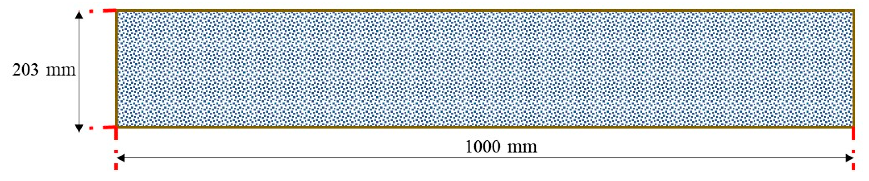
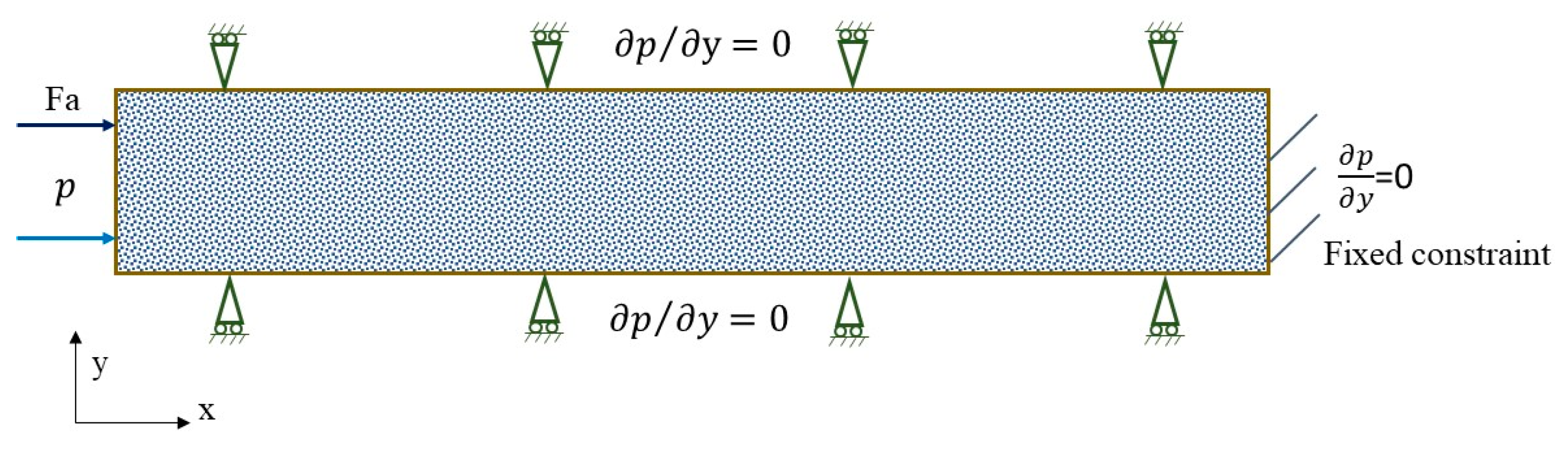
3.1. Model Definition and Boundary Conditions

The dimensions of the model are based on the coal sample used in the experimental study [29], as indicated in Figure 1. In the experimental study, the macro-reconstituted coal sample is a core cylinder with a diameter of 203 mm and a length of 1000 mm. Therefore, the 2D numerical model is 203 mm in height and 1000 mm in length.
The boundary conditions adopted for this model are illustrated in Figure 2. From the perspective of solid mechanics, as the sample is enclosed in a steel cylinder, the circumference of the sample is subjected to the restriction of the apparatus in an axial direction. Therefore, both the top and bottom of the model are assigned as roller boundaries. The right end of the sample is subjected to the cell cap and hence is assumed to be a fixed boundary, and the left end of the sample is subjected to a constant axial load boundary. From the perspective of gas migration in coal, CO2 injection is introduced from the left end of the sample at constant gas pressure. The top boundary, bottom boundary, and right end of the model are set as zero flux conditions.

3.2. Model Parameters

The model input parameters are listed in Table 1, most of the parameters being derived from the associated experimental results. The density and dynamic viscosity of CO2 under different pressure conditions were calculated from the REFPROP database [37].

3.3. Model Meshing

As the model domain is bounded by four boundary segments and there are no isolated or embedded vertices or boundary segments, a 2D-mapped quadrilateral mesh was adopted to mesh the model. The extremely fine element size was selected for the meshing. The completed mesh of the model consists of 2100 domain elements and 242 boundary elements.

4. Results and Discussion

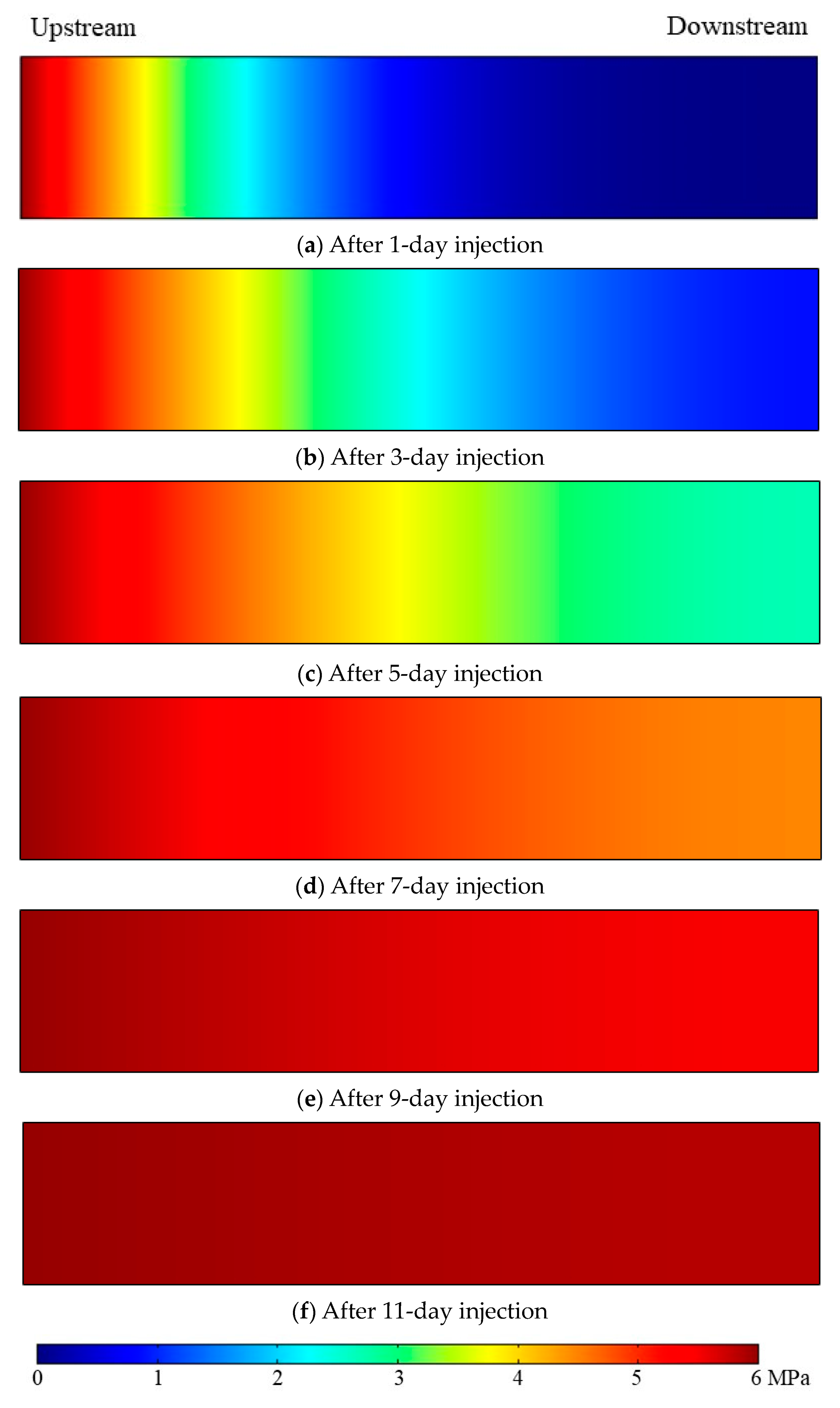
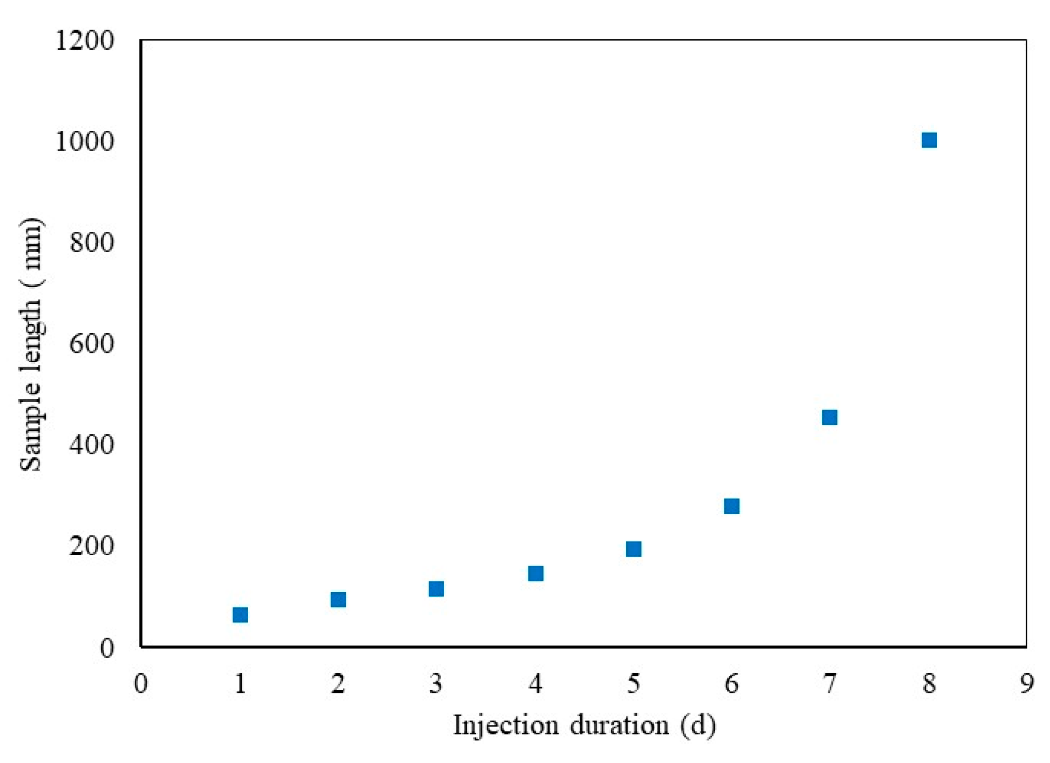
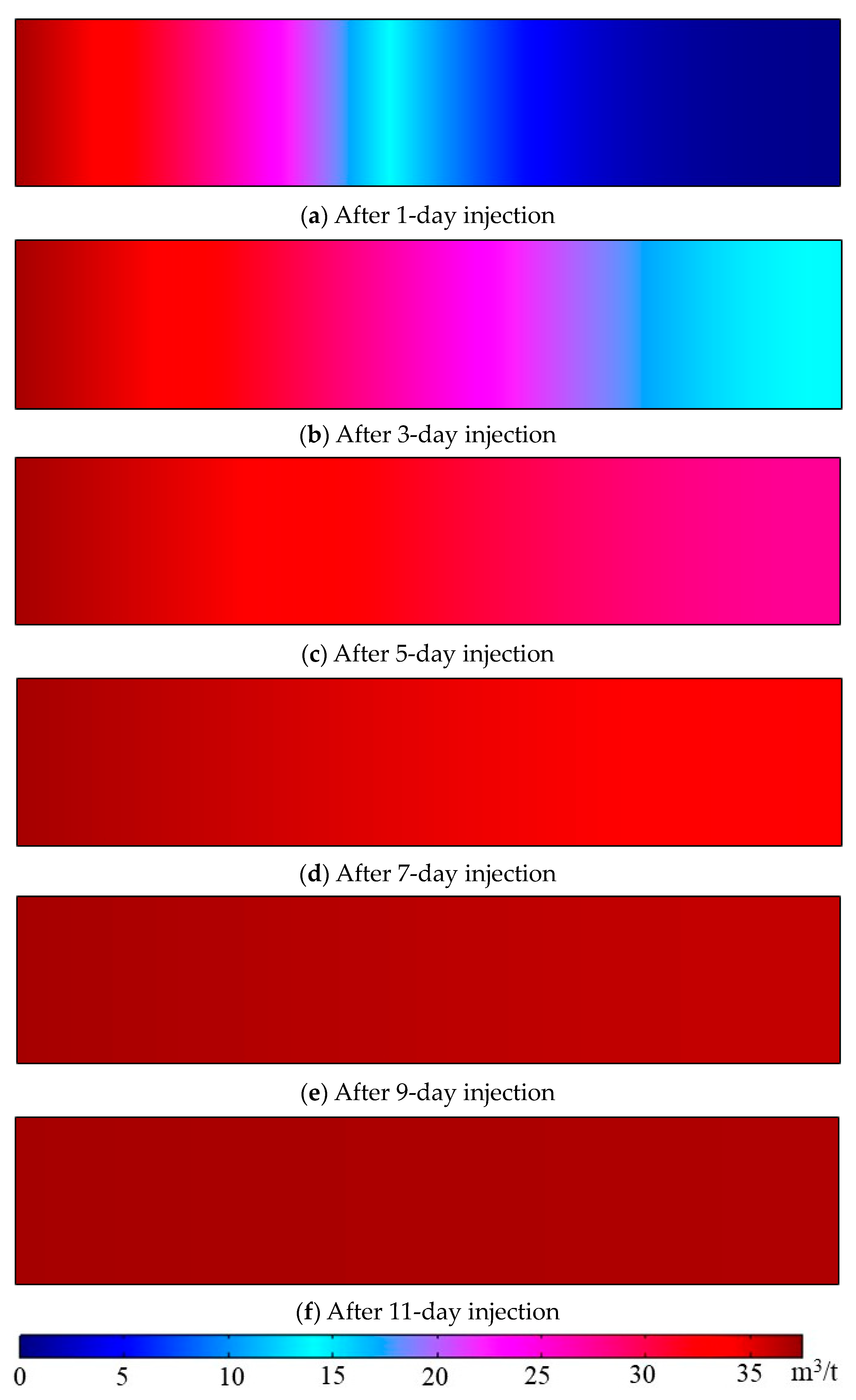
4.1. Effect of Injection Time on Gas Flow Behaviour in Coal

First, gas transportation in the coal sample with time was examined by comparing the CO2 pressure development along the coal sample for various injection durations. Based on the experimental results, CO2 pressure development in the coal sample becomes stable after around eight days of injection for 6 MPa injection. Therefore, a time-dependent study was applied to the calculation with times ranging from 1 to 10 days, with 1 day for each step. Figure 3 shows the CO2 pressure development in the coal sample after 1-day, 3-day, 5-day, 7-day, 9-day, and 11-day CO2 injection at 6 MPa injection pressure under 10 MPa axial load.
As indicated in Figure 3, CO2 pressure develops from the upstream to the downstream with time due to the pressure difference (advection) along the sample, and after around 11 days, the downstream reaches a steady state with a uniform pressure present throughout the sample. However, the pressure development rate varies with time, as indicated in Figure 3. In order to study the rate of CO2 pressure development along the sample with time, a sample length for which the CO2 pressure was greater than 5 MPa was selected. Figure 4 illustrates the sample length (where CO2 pressure is greater than 5 MPa) variation with injection duration.
Based on the information provided by Figure 3 and Figure 4, CO2 migrates in coal at a relatively slow and steady rate in the first few days after injection. The sample length for which the inside CO2 pressure is greater than 5 MPa is around 65 mm, 93 mm, 115 mm, 145 mm, and 193 mm after 1-day, 2-day, 3-day, 4-day, and 5-day injections, respectively. However, this length significantly increases to 455 mm after a seven-day CO2 injection, which demonstrates that the sample becomes more permeable with the development of CO2 pressure along it. As indicated in Figure 3, CO2 pressure development accelerates after the CO2 migrates downstream, which means the effect of the reduction of effective stress on the enhancement of sample permeability dominates the permeability variation of coal over the negative effect of permeability reduction induced by the adsorption of CO2-induced coal matrix swelling.
Figure 5 shows the modeling results of CO2 concentration along the sample after 1-day, 3-day, 5-day, 7-day, 9-day, and 11-day injections, respectively. Similar to the CO2 pressure development with time, the amount of CO2 injected into the sample increases with injection duration at a slow rate in the first few days of injection, followed by a much more rapid concentration development after a five-day CO2 injection. The increased permeability of coal at the later stage of injection significantly improves CO2 transportation in coal, which contributes to the considerable increment of CO2 concentration in coal.

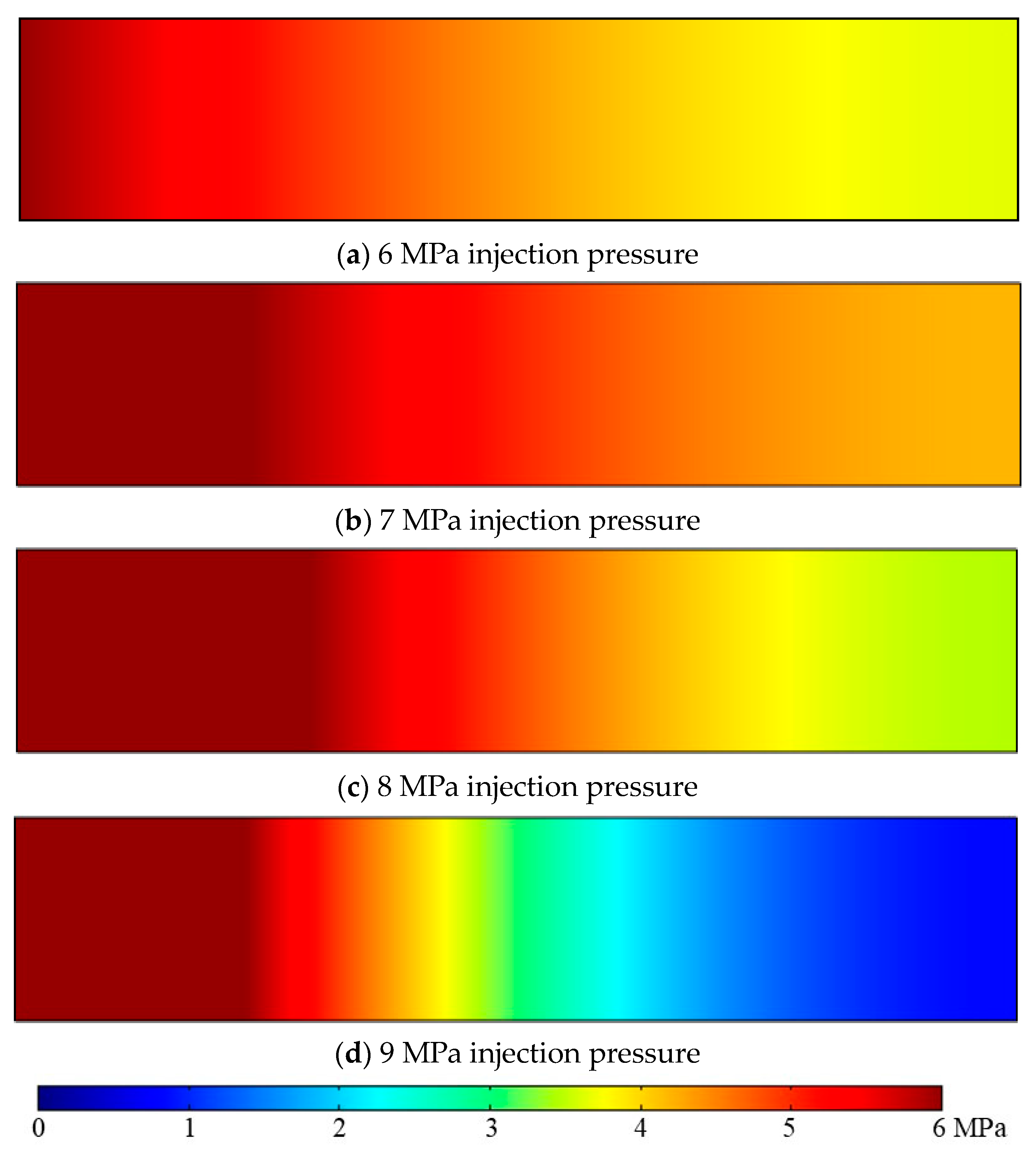
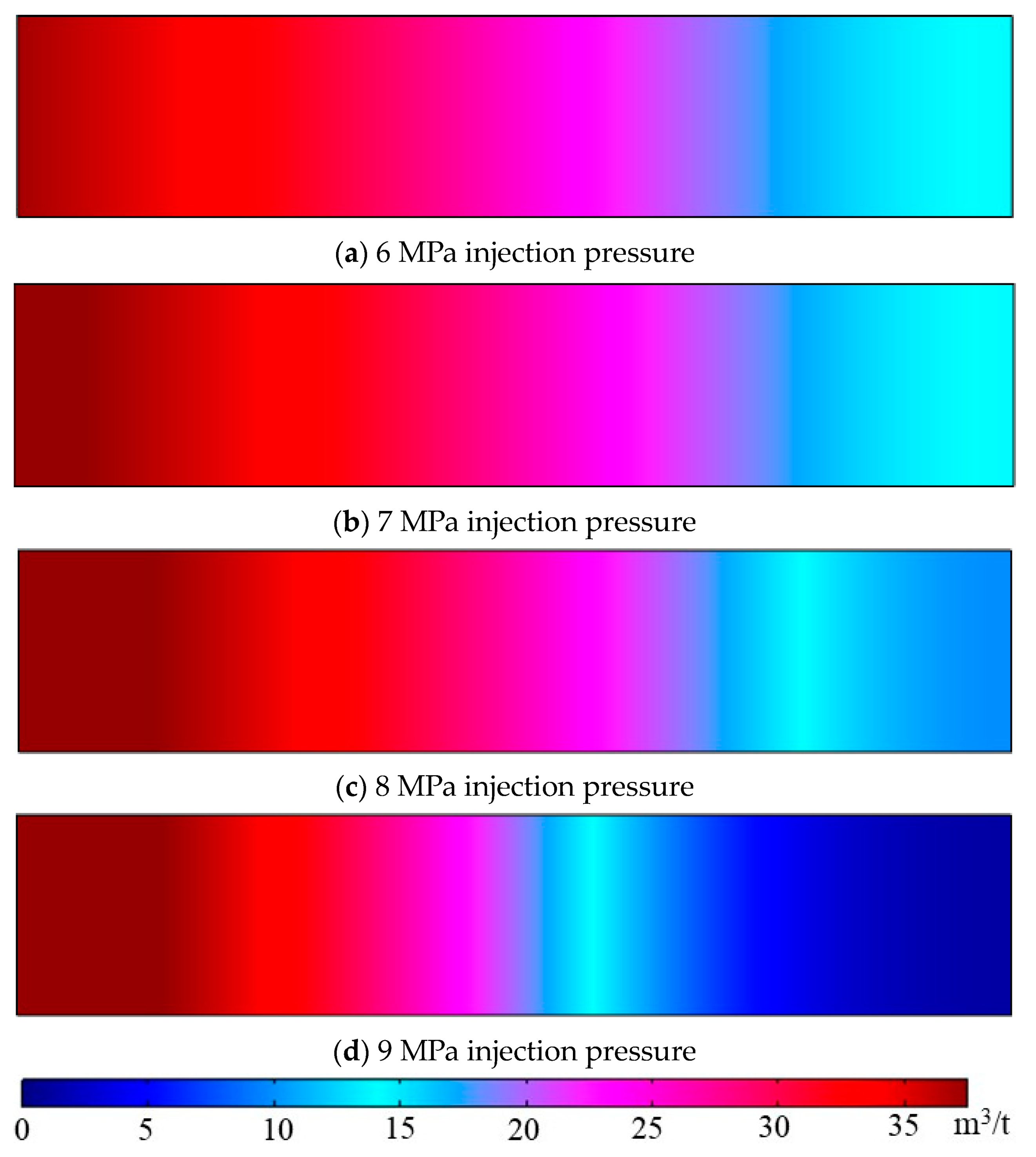
4.2. Effect of CO2 Injection Pressure on Gas Flow Behaviour in Coal

Increasing injection pressure raises pore pressure in coal, which results in cleat openings or fractures as the effective stress applied to coal is consequently reduced. Hence, the permeability of coal is increased with enhanced gas flow, and this effect intensifies with the increase of injection pressure. However, this is applicable for non-sorption gases such as N2 injection. Carbon dioxide has great adsorption affinity to coal for its more linear structure endowed with a high quadrupole moment [38]; the adsorbed CO2 molecules in coal cause strain to be induced between the gas layer and coal pore walls, which can narrow or even close the cleats for gas flow, resulting in reduced gas flow and consequently, reduced permeability. This reduction of permeability due to the adsorption of CO2 increases with increasing CO2 injection pressure since studies have demonstrated that the amount of gas adsorbed in coal increases with increasing pressure to some extent [39,40]. CO2 injection pressure is an important parameter for field applications and should be high enough to deliver sufficient CO2 into the coal seam while maintaining the integrity of the seam. However, coal swelling induced by the adsorption of CO2 increases to some extent with increasing CO2 pressure [41,42,43], which causes permeability reduction and further complicates CO2 migration in coal. Therefore, this part of the study was to investigate the effect of CO2 injection pressure on CO2 transportation behavior in coal.
Figure 6 shows the pressure development of CO2 along the sample at 6 MPa, 7 MPa, 8 MPa, and 9 MPa injection pressures under 10 MPa axial stress. In order to compare the CO2 migration behaviors for different injection pressures, the same injection duration (six days in this case) was selected to ensure that the injection pressure was the only variable for the different injection scenarios.
As demonstrated in Figure 6, increasing the injection pressure from 6 MPa to 7 MPa causes greater pressure development in the sample as the downstream pressure develops to around 3.64 MPa and 4.19 MPa, respectively. Although it is believed that higher CO2 injection pressure favors greater coal matrix swelling and the associated permeability reduction, the improved gas pressure development along the sample for 7 MPa CO2 injection indicates that the permeability reduction caused by CO2 adsorption-induced strain is insignificant compared with the enhanced advection flux under higher CO2 injection pressures. However, the CO2 migration pattern in the sample exhibits different behaviors when the injection pressure increases to 8 MPa and 9 MPa, as shown in Figure 6. Lower pressure development was observed from the simulation results for 8 MPa CO2 injection pressure than for 7 MPa, as the downstream pressure reached around 3.45 MPa for 8 MPa injection pressure. As the model condition is maintained at 37 °C and 8 MPa, the CO2 is in a super-critical state in which the hydrodynamic properties of CO2 significantly change. Both the density and dynamic viscosity of 8 MPa super-critical CO2 is relatively higher than those of 7 MPa sub-critical CO2. Therefore, the increased advection flow due to the increasing pressure difference for 8 MPa injection is overshadowed by the obstruction of CO2 flows with greater density and viscosity. This effect is significantly enhanced for 9 MPa injection pressure, as the downstream pressure developed only to around 0.83 MPa after a six-day injection. Both the density and viscosity of 9 MPa CO2 are considerably higher than those of sub-critical CO2, and this highly dense and viscous super-critical CO2 faces greater obstacles when traveling through the sample.
Further, Table 2 shows the minimum porosity of the sample under different injection pressures. The areas where the minimum porosity of the sample is found are at the injection site, where the greatest CO2 pressure is present. As indicated in Table 2, the value of the minimum porosity of the sample decreases with increasing CO2 injection pressure, which indicates that the increment of porosity due to reduced effective stress is less than the reduction of porosity due to CO2 adsorption-induced strain. Therefore, the overall variation of sample porosity decreases with increasing injection pressure, which leads to greater permeability reduction for higher CO2 injection pressure. In addition, the time required for the downstream to achieve a stable state (when the downstream pressure is greater than 95% of its corresponding injection pressure, it is considered as the stable state) is around 10 days, 10 days, 13 days, and 20 days for 6 MPa, 7 MPa, 8 MPa, and 9 MPa injection pressure, respectively, which is consistent with the above analysis that super-critical CO2 injection faces greater obstacles traveling in the coal sample. Most CO2 sequestration demonstrations are preferred to be implemented in deep-buried coal seams where the pressure and temperature of the environment are beyond the critical point, and the above simulation results suggest that migration of super-critical CO2 in deep-buried coal seams is the main challenge for CO2 sequestration projects.
Figure 7 shows the distribution of CO2 concentration along the sample for different CO2 injection pressures under 10 MPa axial stress after a three-day injection. Similarly, increasing injection pressure from 6 MPa to 7 MPa is accompanied by a slight enhancement of CO2 concentration, which can be attributed to the greater advection flow for higher injection pressure. However, when the injection pressure further increases to the super-critical phase, evident reductions in CO2 concentration development are observed, especially for 9 MPa super-critical injection. Permeability reduction with the increase of injection pressure for super-critical CO2 injection impedes CO2 traveling through the sample. Additionally, the much higher density and dynamic viscosity of super-critical CO2 further obstruct the passage of CO2 within the sample. For example, the density of CO2 at 37 °C is 209.94 kg/m3, 324.02 kg/m3, and 610.30 kg/m3 for 7 MPa, 8 MPa, and 9 MPa pressures, respectively, and dynamic viscosity of CO2 at 37 °C is 19.28 μPa*s, 23.85 μPa*s, and 45.52 μPa*s, for 7 MPa, 8 MPa, and 9 MPa pressures, respectively.

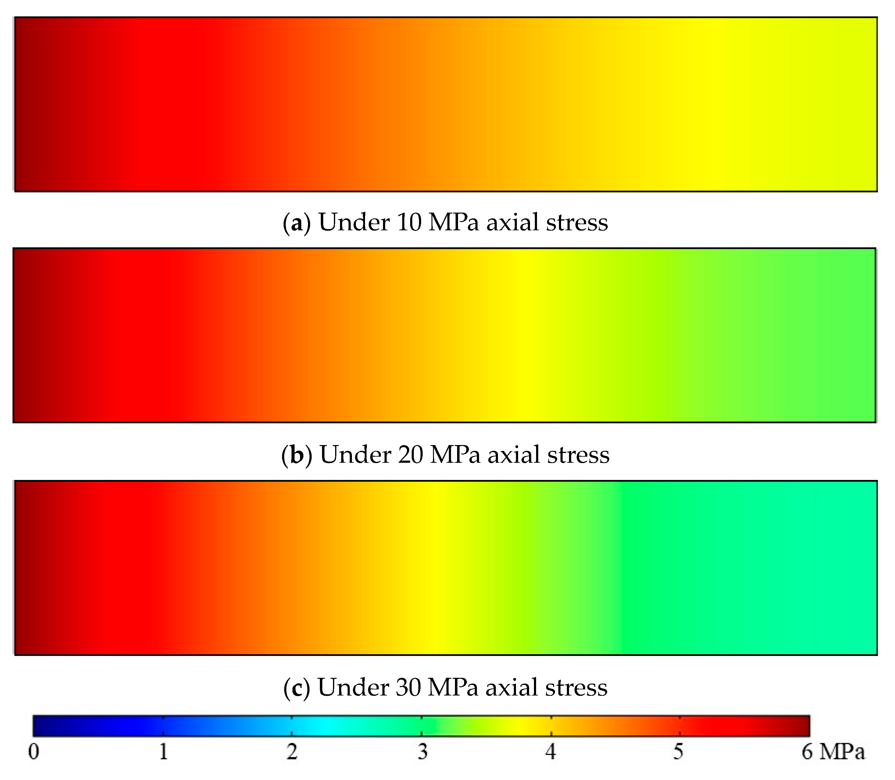
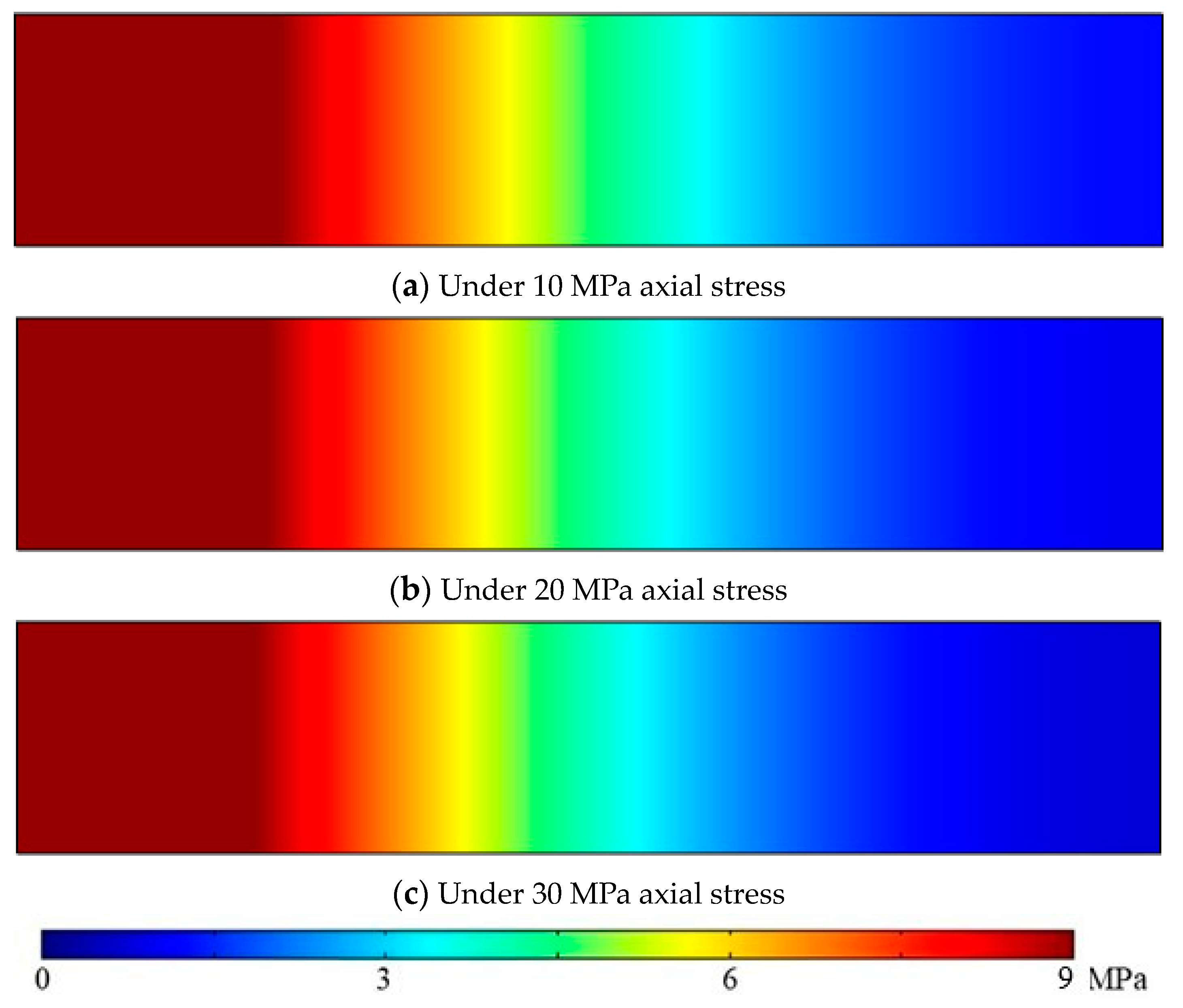
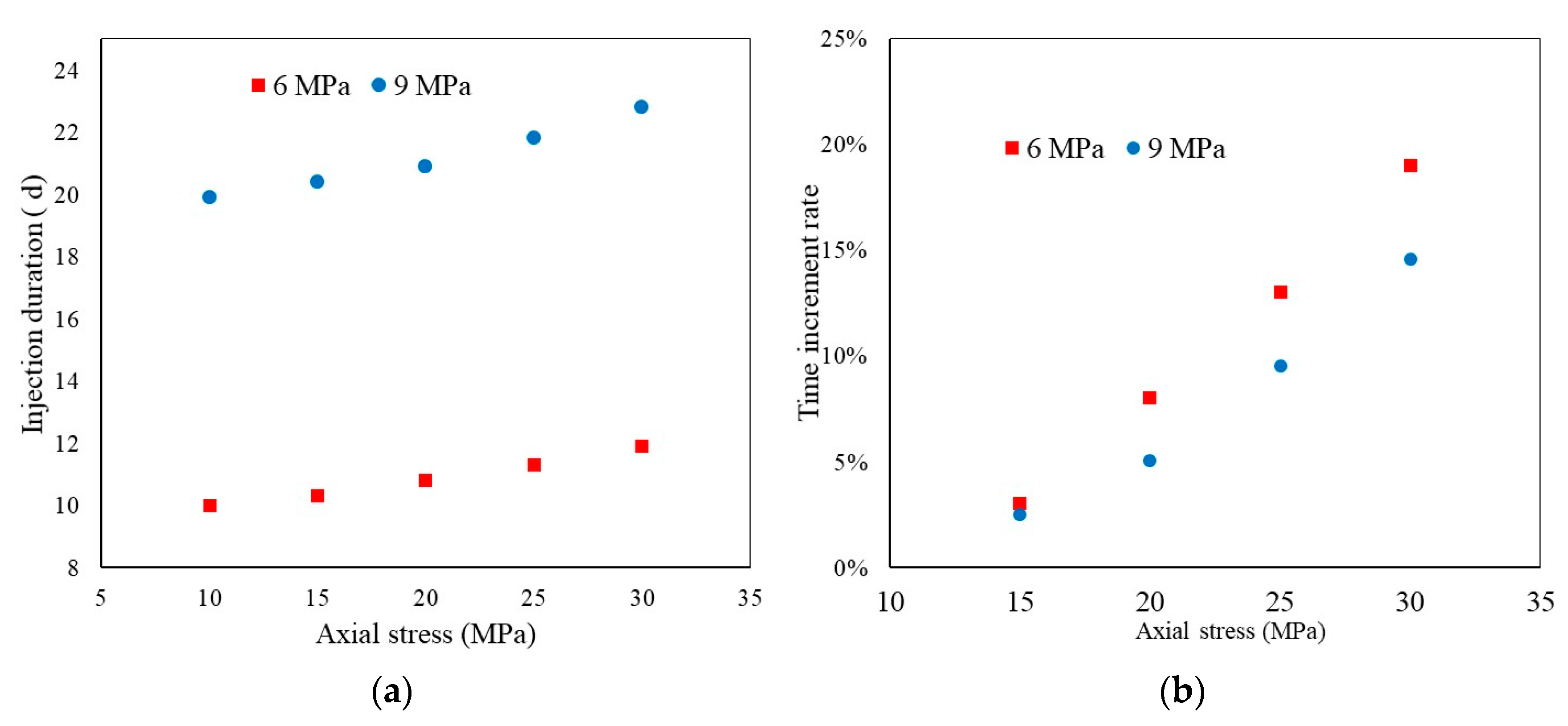
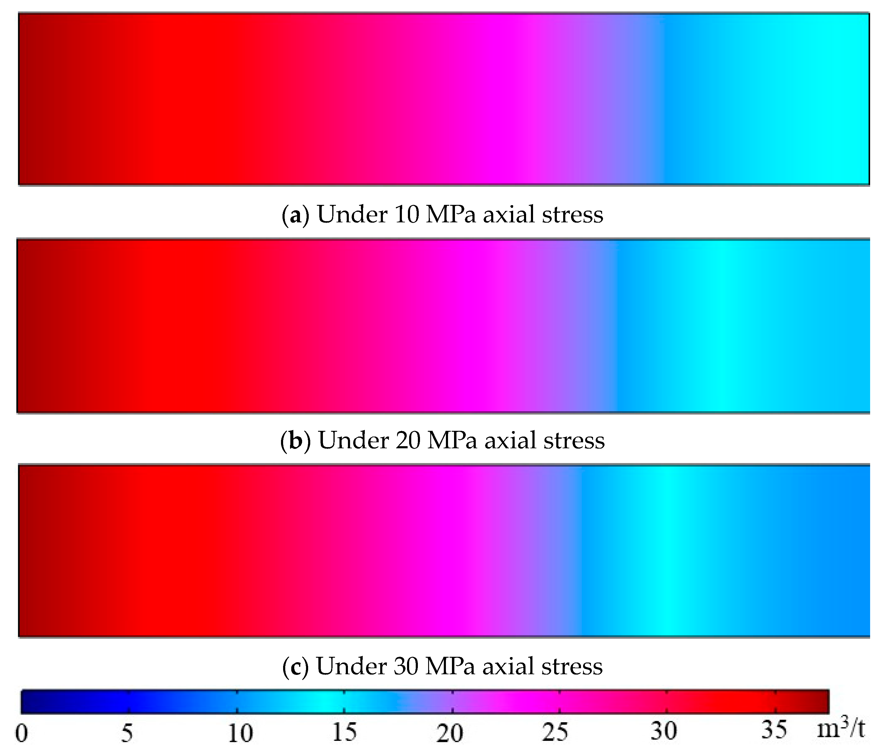
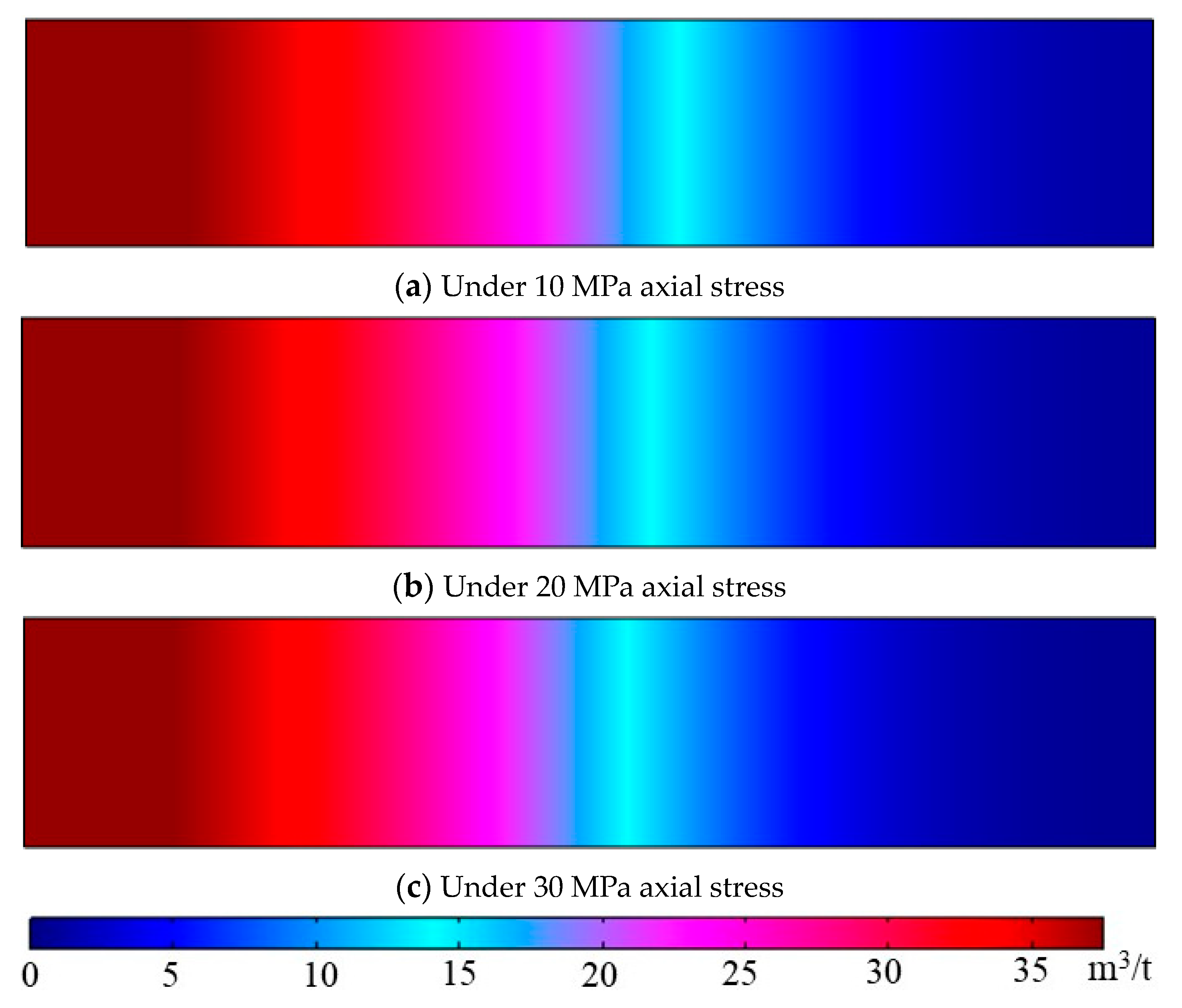
4.3. Effect of Buried Depth on Gas Flow Behaviours in Coal

Deep coal seams are generally ideal target sinks for CO2 sequestration, as there is less risk of the injected CO2 back-migrating into the atmosphere [13,44]. However, the high-stress environment deep underground may create great obstacles for CO2 to flow in the cleat system by closing fracture apertures, which generally require greater injection pressure to deliver CO2 into coal seams. According to the previous discussion, higher CO2 injection pressures, especially when in the super-critical state, may limit the flowability of CO2, which complicates CO2 migration patterns in coal. Therefore, this part of the study was dedicated to an investigation of the effect of stress conditions (buried depth) on CO2 flow behavior in coal.
Figure 8 and Figure 9 depict CO2 pressure development in the sample under different axial stresses (from 10 MPa to 30 MPa) after a six-day injection of 6 MPa CO2 and 9 MPa CO2, respectively. As indicated in Figure 8 and Figure 9, CO2 pressure is less developed under higher stress conditions, which indicates that with the increase of axial stress (buried depth), CO2 experiences greater difficulty migrating through the sample. This is in accordance with the previous analysis that at greater depth, CO2 movement is restricted because of the reduced flow paths due to the high-stress environment.
A comparison of the results in Figure 8 and Figure 9 reveals that greater alterations in CO2 flow behaviors due to changes in effective stress are found for 6 MPa CO2 injection compared with the associated changes for 9 MPa CO2 injection. Figure 10a shows the time required for the downstream to reach the stable state (where downstream pressure is greater than 95% of the corresponding injection pressure) for each injection pressure under various stress conditions, and Figure 10b demonstrates the increment rate of injection time to achieve a stable state at downstream. As indicated in Figure 10a, it is evident that under high-stress conditions, a longer injection time is required for the CO2 pressure to develop downstream for all the injection scenarios. The rate of increment of injection time to achieve a stable state downstream also increases with increasing axial stress, as shown in Figure 10b, and the gap between 6 MPa injection and 9 MPa injection increases with axial stress. This means that low injection pressures are more likely to be affected by changes in the stress condition, and this effect is enhanced in a high-stress environment. Therefore, it can be concluded that high CO2 injection pressures are preferred for CO2 sequestration projects with great buried depths. However, it should be mentioned that the CO2 injection pressure needs to be well-managed to avoid the fracturing of the coal seam, which may lead to the early breakthrough of the injected CO2.
Figure 11 and Figure 12 depict the modeling results of the distribution of CO2 concentration in the sample under different axial stresses after a three-day injection for 6 MPa CO2 and 9 MPa CO2 injection pressure, respectively. Similar to the effect of axial stress on the variation of pressure development, higher stress conditions restrict the adsorption of CO2, and the amount of CO2 injected into the sample decreases with increasing axial stress for both 6 MPa and 9 MPa CO2 injection. A higher injection pressure (9 MPa in this case) appears to be less affected by the variation of stress conditions, which further demonstrates the effectiveness of high CO2 injection pressures during CO2 sequestration in deeply buried coal seams.

5. Implications for CO2 Sequestration in Deep Coal Seams

Deep coal seams are ideal sinks for CO2 sequestration for their great storage potential and vast availability worldwide. High CO2 injection pressures are required to overcome the high-stress condition deep underground, and CO2 is, therefore, in its super-critical state along with the high-temperature condition. The findings of the present study suggest that migration of super-critical CO2 in deep-buried coal seams is the main challenge for CO2 sequestration projects since super-critical CO2 injections face greater obstacles when flowing through a coal seam, but the ultimate storage of CO2 can be achieved for higher injection pressures if sufficient injection time is given. Further, according to the result of pressure development for different axial stresses, high injection pressures are less affected by stress conditions compared with low injection pressures. Therefore, high injection pressures are preferred for economic and efficient CO2 sequestration with great buried depths. However, the CO2 injection pressure needs to be well-managed to avoid compromising the mechanical properties of the coal seam, which may lead to the early breakthrough of the injected CO2. As the permeability reduction due to the adsorption of CO2 is the major issue restricting the progress of field projects, permeability enhancement measures are therefore suggested. Injection of an inert gas such as N2 has a stripping effect which can partly restore coal seam permeability. Other measures, such as thermal treatment and contained fracturing of the target coal seams, are also recommended; however, these operations need to be well-managed to minimize the disturbance to the coals and overlying strata. Since the associated macro-scale experimental studies were conducted using reconstructed coal samples, the samples are homogeneous in nature. Therefore, the model in the present study was also assumed to be homogeneous, the results of which cannot precisely mirror field conditions. Therefore, it is suggested to perform similar simulations on gas flow behaviors in heterogeneous coal models. Additionally, as discussed in the introduction, temperature has an intricate effect on CO2 flow behaviors in coal. It is therefore suggested to study the effect of temperature, especially high temperature, on the hydro-mechanical performance of coal with the adsorption of CO2.

6. Conclusions

Few studies to date have attempted to conduct CO2 flow experiments on macro-scale coal samples as extensive time and labor are required to complete the associated tests. Numerical modeling can remove these barriers. In this study, a coupled gas flow, mechanical deformation, and sorption-induced deformation finite element model are developed to investigate CO2 flow behavior in a laboratory-scale model under various test conditions. A general porosity model considering mechanical deformation-induced changes in pore volume and adsorption-induced changes in pore volume was adopted to describe the variation of model porosity. The mechanical deformation was modeled with the consideration of in situ stress and pore pressure changes. The coupling between gas flow behavior and variation of porosity was achieved through the cubic law, and the developed model was written in COMSOL Multiphysics to simulate CO2 flow behavior during CO2 sequestration in coal seams under various conditions. The following conclusions can be drawn from the results.
The sample is more permeable with pressure development at low injection pressure, which indicates that the effect of the reduction of effective stress on the enhancement of sample permeability is greater than the negative effect of permeability reduction due to CO2 adsorption. Similarly, CO2 concentration in coal increases with injection duration, especially at a later stage, due to the greater enhancement of sample permeability.
In the lower CO2 injection pressure range (less than 8 MPa), CO2 pressure development in coal increases with increasing injection pressure due to enhanced advection flux, while super-critical CO2 injection faces greater obstacles in migrating within the coal sample compared to sub-critical CO2 injections because of its significantly higher viscosity and density as well as the reduction in permeability due to adsorption-induced strain. However, the ultimate pressure development or adsorption capacity increases with injection pressure regardless of the CO2 phase.
CO2 pressure and concentration development decrease with increasing axial stress (buried depth), which is related to the increased effective stress-induced reduction in gas flow paths.
The effect of axial stress on CO2 migration in coal is more influential on lower injection pressures than higher super-critical CO2 injection pressures, which demonstrates the effectiveness of using high injection pressures during CO2 sequestration in high-stress deep coal seams. However, injection pressure needs to be well-managed to avoid compromising the mechanical properties of the coal seam and cap rock, rendering less effective storage of CO2.

Author Contributions

Conceptualization, H.W. and Z.W.; methodology, H.W., Z.W., and H.Y.; software, C.J. and X.Z.; writing, H.W.; reviewing and editing, C.J., X.Z., and L.L.; All authors have read and agreed to the published version of the manuscript.

Funding

This research was funded by the National Natural Science Foundation of China (Grant No. 42005133, 92162105); the Hebei Natural Science Foundation (Grant No. D2022402005); the Key Program of Science and Technology Research Project of the Colleges and Universities of Hebei Province (Grant No. ZD2022130).

Institutional Review Board Statement

Not applicable.

Informed Consent Statement

Not applicable.

Data Availability Statement

The data used to support the findings of this study are available from the corresponding author upon reasonable request.

Conflicts of Interest

The authors declare no conflict of interest.

References

  1. Mavrodieva, A.V.; Shaw, R. Disaster and Climate Change Issues in Japan’s Society 5.0—A Discussion. Sustainability 2020, 12, 1893. [Google Scholar] [CrossRef]
  2. Summers, J.K.; Lamper, A.; McMillion, C.; Harwell, L.C. Observed Changes in the Frequency, Intensity, and Spatial Patterns of Nine Natural Hazards in the United States from 2000 to 2019. Sustainability 2022, 14, 4158. [Google Scholar] [CrossRef] [PubMed]
  3. Li, X.; Long, D.; Scanlon, B.R.; Mann, M.E.; Li, X.; Tian, F.; Sun, Z.; Wang, G. Climate Change Threatens Terrestrial Water Storage over the Tibetan Plateau. Nat. Clim. Chang. 2022, 12, 801–807. [Google Scholar] [CrossRef]
  4. Hossain, B.; Sohel, M.S.; Ryakitimbo, C.M. Climate Change Induced Extreme Flood Disaster in Bangladesh: Implications on People’s Livelihoods in the Char Village and Their Coping Mechanisms. Prog. Disaster Sci. 2020, 6, 100079. [Google Scholar] [CrossRef]
  5. Al-Ghussain, L. Global Warming: Review on Driving Forces and Mitigation. Environ. Prog. Sustain. Energy 2019, 38, 13–21. [Google Scholar] [CrossRef]
  6. Statistical Review of World Energy Energy Economics Home. Available online: https://www.bp.com/en/global/corporate/energy-economics/statistical-review-of-world-energy.html (accessed on 31 March 2023).
  7. Climate Action—United Nations Sustainable Development. Available online: https://www.un.org/sustainabledevelopment/climate-action/ (accessed on 31 March 2023).
  8. The Paris Agreement UNFCCC. Available online: https://unfccc.int/process-and-meetings/the-paris-agreement (accessed on 31 March 2023).
  9. Zhang, X.G.; Ranjith, P.G.; Perera, M.S.A.; Ranathunga, A.S.; Haque, A. Gas Transportation and Enhanced Coalbed Methane Recovery Processes in Deep Coal Seams: A Review. Energy Fuels 2016, 30, 8832–8849. [Google Scholar] [CrossRef]
  10. Zhu, W.; Liu, S.; Zhang, X.; Wei, C. Coupled coal–gas interaction during CBM and CO2-ECBM recovery in coal seams: A critical review. Geomech. Geophys. Geo-Energy Geo-Resour. 2022, 8, 1–32. [Google Scholar] [CrossRef]
  11. Tyne, R.L.; Barry, P.H.; Lawson, M.; Byrne, D.J.; Warr, O.; Xie, H.; Hillegonds, D.J.; Formolo, M.; Summers, Z.M.; Skinner, B.; et al. Rapid Microbial Methanogenesis during CO2 Storage in Hydrocarbon Reservoirs. Nature 2021, 600, 670–674. [Google Scholar] [CrossRef]
  12. Gunter, W.D.; Gentzis, T.; Rottenfusser, B.A.; Richardson, R.J.H. Deep Coalbed Methane in Alberta, Canada: A Fuel Resource with the Potential of Zero Greenhouse Gas Emissions. Energy Convers. Manag. 1997, 38, S217–S222. [Google Scholar] [CrossRef]
  13. Pan, Z.; Ye, J.; Zhou, F.; Tan, Y.; Connell, L.D.; Fan, J. CO2 Storage in Coal to Enhance Coalbed Methane Recovery: A Review of Field Experiments in China. Int. Geol. Rev. 2017, 60, 754–776. [Google Scholar] [CrossRef]
  14. Zhang, X.; Ranjith, P.G.; Ranathunga, A.S. Sub- and Super-Critical Carbon Dioxide Flow Variations in Large High-Rank Coal Specimen: An Experimental Study. Energy 2019, 181, 148–161. [Google Scholar] [CrossRef]
  15. Cui, X.; Bustin, R.M.; Chikatamarla, L. Adsorption-Induced Coal Swelling and Stress: Implications for Methane Production and Acid Gas Sequestration into Coal Seams. J. Geophys. Res. Solid. Earth 2007, 112, 10202. [Google Scholar] [CrossRef]
  16. Qu, H.; Liu, J.; Pan, Z.; Connell, L. Impact of Matrix Swelling Area Propagation on the Evolution of Coal Permeability under Coupled Multiple Processes. J. Nat. Gas. Sci. Eng. 2014, 18, 451–466. [Google Scholar] [CrossRef]
  17. Zhang, X.; Ranjith, P.G. Experimental Investigation of Effects of CO2 Injection on Enhanced Methane Recovery in Coal Seam Reservoirs. J. CO2 Util. 2019, 33, 394–404. [Google Scholar] [CrossRef]
  18. Zhang, X.; Gamage, R.P.; Perera, M.S.A.; Ranathunga, A.S. Effects of Water and Brine Saturation on Mechanical Property Alterations of Brown Coal. Energies 2018, 11, 1116. [Google Scholar] [CrossRef]
  19. Yao, H.; Chen, Y.; Liang, W.; Li, Z.; Song, X. Experimental Study on the Permeability Evolution of Coal with CO2 Phase Transition. Energy 2023, 266, 126531. [Google Scholar] [CrossRef]
  20. Wang, R.; Wang, Q.; Niu, Q.; Pan, J.; Wang, H.; Wang, Z. CO2 Adsorption and Swelling of Coal under Constrained Conditions and Their Stage-Change Relationship. J. Nat. Gas. Sci. Eng. 2020, 76, 103205. [Google Scholar] [CrossRef]
  21. Vishal, V. In-Situ Disposal of CO2: Liquid and Supercritical CO2 Permeability in Coal at Multiple down-Hole Stress Conditions. J. CO2 Util. 2017, 17, 235–242. [Google Scholar] [CrossRef]
  22. Chen, L.; Zhao, M.; Li, X.; Liu, Y. Impact Research of CH4 Replacement with CO2 in Hydrous Coal under High Pressure Injection. Min. Mineral. Depos. 2022, 16, 121–126. [Google Scholar] [CrossRef]
  23. Perera, M.S.A.; Ranjith, P.G.; Choi, S.K.; Airey, D. Investigation of Temperature Effect on Permeability of Naturally Fractured Black Coal for Carbon Dioxide Movement: An Experimental and Numerical Study. Fuel 2012, 94, 596–605. [Google Scholar] [CrossRef]
  24. Jasinge, D.; Ranjith, P.G.; Choi, S.K. Effects of Effective Stress Changes on Permeability of Latrobe Valley Brown Coal. Fuel 2011, 90, 1292–1300. [Google Scholar] [CrossRef]
  25. Connell, L.D. A New Interpretation of the Response of Coal Permeability to Changes in Pore Pressure, Stress and Matrix Shrinkage. Int. J. Coal Geol. 2016, 162, 169–182. [Google Scholar] [CrossRef]
  26. Ren, J.; Niu, Q.; Wang, Z.; Wang, W.; Yuan, W.; Weng, H.; Sun, H.; Li, Y.; Du, Z. CO2 Adsorption/Desorption, Induced Deformation Behavior, and Permeability Characteristics of Different Rank Coals: Application for CO2-Enhanced Coalbed Methane Recovery. Energy Fuels 2022, 36, 5709–5722. [Google Scholar] [CrossRef]
  27. De Silva, P.N.K.; Ranjith, P.G. Advanced Core Flooding Apparatus to Estimate Permeability and Storage Dynamics of CO2 in Large Coal Specimens. Fuel 2013, 104, 417–425. [Google Scholar] [CrossRef]
  28. Ranathunga, A.S.; Perera, M.S.A.; Ranjith, P.G.; De Silva, G.P.D. A Macro-Scale View of the Influence of Effective Stress on Carbon Dioxide Flow Behaviour in Coal: An Experimental Study. Geomech. Geophys. Geo-Energy Geo-Resour. 2016, 3, 13–28. [Google Scholar] [CrossRef]
  29. Zhang, X.; Jin, C.; Zhang, D.; Zhang, C.; Ranjith, P.G.; Yuan, Y. Carbon Dioxide Flow Behaviour in Macro-Scale Bituminous Coal: An Experimental Determination of the Influence of Effective Stress. Energy 2023, 268, 126754. [Google Scholar] [CrossRef]
  30. Li, Z.; Yu, H.; Bai, Y. Numerical Simulation of CO2-ECBM Based on Multi-Physical Field Coupling Model. Sustainability 2022, 14, 11789. [Google Scholar] [CrossRef]
  31. Cun, Z.; Bo, L.; Ziyu, S.; Jinbao, L.; Jinlong, Z. Breakage Mechanism and Pore Evolution Characteristics of Gangue Materials under Compression. Acta Geotech. 2022, 17, 4823–4835. [Google Scholar] [CrossRef]
  32. Connell, L.D.; Lu, M.; Pan, Z. An Analytical Coal Permeability Model for Tri-Axial Strain and Stress Conditions. Int. J. Coal Geol. 2010, 84, 103–114. [Google Scholar] [CrossRef]
  33. Chen, Z.; Liu, J.; Elsworth, D.; Connell, L.D.; Pan, Z. Impact of CO2 Injection and Differential Deformation on CO2 Injectivity under In-Situ Stress Conditions. Int. J. Coal Geol. 2010, 81, 97–108. [Google Scholar] [CrossRef]
  34. Xue, Y.; Ranjith, P.G.; Chen, Y.; Cai, C.; Gao, F.; Liu, X. Nonlinear Mechanical Characteristics and Damage Constitutive Model of Coal under CO2 Adsorption during Geological Sequestration. Fuel 2023, 331, 125690. [Google Scholar] [CrossRef]
  35. Zhu, W.C.; Wei, C.H.; Liu, J.; Qu, H.Y.; Elsworth, D. A Model of Coal–Gas Interaction under Variable Temperatures. Int. J. Coal Geol. 2011, 86, 213–221. [Google Scholar] [CrossRef]
  36. Langmuir, I. The Constitution and Fundamental Properties of Solids and Liquids Part I. Solids. J. Am. Chem. Soc. 1916, 38, 2221–2295. [Google Scholar] [CrossRef]
  37. Lemmon, E.W.; Huber, M.L.; McLinden, M.O. NIST Standard Reference Database 23: Reference Fluid Thermodynamic and Transport Properties-REFPROP, Version 9.1; National Institute of Standards and Technology: Gaithersburg, MD, USA, 2013. [Google Scholar]
  38. Czerw, K. Methane and Carbon Dioxide Sorption/Desorption on Bituminous Coal—Experiments on Cubicoid Sample Cut from the Primal Coal Lump. Int. J. Coal Geol. 2011, 85, 72–77. [Google Scholar] [CrossRef]
  39. Dutta, P.; Bhowmik, S.; Das, S. Methane and Carbon Dioxide Sorption on a Set of Coals from India. Int. J. Coal Geol. 2011, 85, 289–299. [Google Scholar] [CrossRef]
  40. Bae, J.S.; Bhatia, S.K. High-Pressure Adsorption of Methane and Carbon Dioxide on Coal. Energy Fuels 2006, 20, 2599–2607. [Google Scholar] [CrossRef]
  41. Vandamme, M.; Brochard, L.; Lecampion, B.; Coussy, O. Adsorption and Strain: The CO2-Induced Swelling of Coal. J. Mech. Phys. Solids 2010, 58, 1489–1505. [Google Scholar] [CrossRef]
  42. Hol, S.; Spiers, C.J. Competition between Adsorption-Induced Swelling and Elastic Compression of Coal at CO2 Pressures up to 100 MPa. J. Mech. Phys. Solids 2012, 60, 1862–1882. [Google Scholar] [CrossRef]
  43. Day, S.; Fry, R.; Sakurovs, R. Swelling of Australian Coals in Supercritical CO2. Int. J. Coal Geol. 2008, 74, 41–52. [Google Scholar] [CrossRef]
  44. Ge, Z.; Zeng, M.; Cheng, Y.; Wang, H.; Liu, X. Effects of Supercritical CO2 Treatment Temperature on Functional Groups and Pore Structure of Coals. Sustainability 2019, 11, 7180. [Google Scholar] [CrossRef]
Figure 1. Dimensions of sample model.
Sustainability 15 08002 g001
Figure 2. Boundary conditions of model.
Sustainability 15 08002 g002
Figure 3. CO2 pressure development in coal for 6 MPa injection pressure at 10 MPa axial load.
Sustainability 15 08002 g003
Figure 4. Variation of sample length (inside CO2 pressure is greater than 5 MPa) with injection duration.
Sustainability 15 08002 g004
Figure 5. Variation of CO2 concentration along a sample with injection durations for 6 MPa injection pressure at 10 MPa axial load.
Sustainability 15 08002 g005
Figure 6. CO2 pressure development in coal for different CO2 injection pressures at 10 MPa axial stress after six-day injection.
Sustainability 15 08002 g006
Figure 7. CO2 concentration in coal at different injection pressures under 10 MPa axial stress after three-day injection.
Sustainability 15 08002 g007
Figure 8. CO2 pressure development in coal for different axial stresses at 6 MPa injection pressure after six-day injection.
Sustainability 15 08002 g008
Figure 9. CO2 pressure development in coal for different axial stresses at 9 MPa injection pressure after six-day injection.
Sustainability 15 08002 g009
Figure 10. Relation between (a) time required for downstream to achieve stable and (b) rate of increment of injection time for downstream to achieve stable condition with stress.
Sustainability 15 08002 g010
Figure 11. CO2 concentrations in coal for different axial stresses under 6 MPa injection pressure after three-day injection.
Sustainability 15 08002 g011
Figure 12. CO2 concentrations in coal for different axial stresses under 9 MPa injection pressure after three-day injection.
Sustainability 15 08002 g012
Table 1. Model input parameters.
Model ParameterValue
CO2 properties
Langmuir   pressure   of   CO 2   on   coal   ( P L ) 2.32 MPa
Langmuir   volume   of   CO 2   on   coal   ( V L ) 0.0513 m3/kg
Injection   pressure   ( p )From 6 MPa to 25 MPa
Coal properties
Density   ( ρ c )1450 kg/m3
Young s   modulus   ( E )3.37 GPa
Poisson s   ratio   ( γ )0.263
Table 2. Minimum sample porosity for different CO2 injection pressures under 10 MPa axial stress after six-day injection.
Injection PressureMinimum Porosity
6 MPa6.94%
7 MPa6.87%
8 MPa6.81%
9 MPa6.76%
Disclaimer/Publisher’s Note: The statements, opinions and data contained in all publications are solely those of the individual author(s) and contributor(s) and not of MDPI and/or the editor(s). MDPI and/or the editor(s) disclaim responsibility for any injury to people or property resulting from any ideas, methods, instructions or products referred to in the content.

