Article

General Current Control of Six-Phase-Based Non-Isolated Integrated On-Board Charger with Low Order Harmonic Compensation

by
Mahmoud S. Abdel-Majeed
1,
Abdullah Shawier
1,
Ayman S. Abdel-Khalik
1,*,
Mostafa S. Hamad
2,
Mohamed M. Sedky
1 and
Noha A. Elmalhy
1
1
Department of Electrical Engineering, Alexandria University, Alexandria 21544, Egypt
2
Department of Electrical and Control Engineering, Arab Academy for Science, Technology and Maritime Transport, Alexandria 21913, Egypt
*
Author to whom correspondence should be addressed.
Sustainability 2022, 14(3), 1088; https://doi.org/10.3390/su14031088
Submission received: 18 December 2021 / Revised: 9 January 2022 / Accepted: 15 January 2022 / Published: 18 January 2022

Abstract

:
Electric vehicle charging technology has recently witnessed massive developments due to its significant role in the ever-growing number of electric vehicles on the market. The integrated on-board charger technology (IOBC) represents an effective and attractive solution to reduce EV size, cost, and weight. IOBC technology employs propulsion components, such as the motor and its converter, in the charging process. The main objective of IOBC is to achieve the maximum charging current with zero average/pulsating torque so that mechanical interlocking can be dispensed. Recently, some of the IOBC topologies have adopted machines with six-phase stators to exploit the many advantages of multiphase-based systems. This paper investigates the effect of the winding design, namely, chorded or un-chorded designs, as well as the winding configuration, namely, dual three-phase, asymmetrical, or symmetrical winding configurations, on the current quality of a six-phase-based non-isolated IOBC. The relation between the winding design and the induced low order harmonics in the charging current is first clarified. The required current controller structure is then proposed, which ensures balanced grid line currents with high quality, under either healthy or one-phase fault conditions. Finally, a comparative study between all available designs with the proposed current controller is carried out to validate the theoretical findings.

1. Introduction

A clean, energy-based transportation is now globally required as a major step to hold back climate change and the greenhouse effect. Electric vehicles (EVs) impose themselves as a promising alternative to the conventional diesel engine vehicles. Nowadays, extensive investments are focusing on developing EV-based technologies and their components, such as electric motor design, converter design, innovative control techniques, batteries, and battery chargers [1]. However, one of the major challenges that has curbed the use of EVs widely is the limited range that car can go on one charge [2]. This, in turn, sheds light on developing different charging technologies of EVs, starting from battery design and ending up with charger types. In this context, EV chargers are classified into two main categories: off-board and on-board chargers [3].
Albeit off-board chargers are distinguished by their safety and fast charging competence, this option entails dedicated resources and infrastructure [4]. On the other hand, on-board chargers offer a simple charging solution thanks to their capability of charging directly from AC plugs. However, the charging time is relatively slow due to onboard weight, volume, and cost constraints.
Lately, the idea of integrated on-board chargers has emerged as an alternative solution to overcome the limitations of on-board chargers [5]. IOBCs employ propulsion components, namely, the converter and motor, in the charging process. Thus, the power flows from grid to the battery through the converter, while the motor acts as a smoothing filter. Examples of some single-phase IOBCs are reviewed in [4]. Due to the limited power range of single-phase-based IOBCs, the three-phase IOBCs have shown accelerating potentials in recent literature [6,7]. The main control challenge of this technology is to ensure zero torque production under charging. From the machine point of view, based on the comprehensive review of EVs given in [8], the permanent magnet and induction machines are likely the most common types employed in EVs [9].
Recently, multiphase machines are being favored for EV drivelines over their three-phase counterparts. The fault-tolerance and reduced converter per-phase current/voltage ratings are the main merits of multiphase machines [10,11]. Different multiphase-based IOBC topologies have been proposed in the available literature [10,12,13]. Currently, the six-phase induction machine (SPIM) has been preferred in recent literature to be a reasonable/compromised alternative for three-phase motors. Moreover, SPIM offers less complexity, is cost-effective, and is a more reliable solution compared to other phase orders. The SPIM can easily be rewound using the same standard three-phase stator frames with, theoretically, no practical constraints, besides its capability of being driven using off-the-shelf three-phase converters [14,15]. In the literature, six-phase machines have been proposed with three different winding layouts, namely, dual three-phase (D3P), asymmetrical six-phase (A6P), and symmetrical six-phase (S6P) [16]. Another novel winding layout for six-phase machines, known as pseudo six-phase, has proved to offer a 5% enhancement in the torque density over conventional six-phase winding [17].
Most of the up-to-date literature has emphasized controlling the SPIM under propulsion mode. However, considering SPIM in an IOBC system raises more challenges when standard current controllers are to be preserved. The control technique of a SPIM-based IOBC system should control the machine phase currents in a manner that ensures zero torque production during charging mode. To this end, literature has suggested different solutions to ensure zero torque production. For instance, the concept of phase transformation represents one of the proposed solutions that has been applied to symmetrical and asymmetrical SPIM-based IOBCs to nullify the torque production during battery pack charging [13,18]. In this latter technique, the machine stator is connected to the gird using a two-secondary winding transformer, while the converter is controlled in such a way as to ensure zero fundamental (αβ) current components using conventional PI controllers. In [18], an alternative topology has been proposed and applied to either A6P or S6P machines, which enables fast-charging up to 100% of the traction power rating. The so-called vector PI resonant controller has been employed to control the system under either propulsion or charging modes. Another non-isolated IOBC topology that achieves 100% charging/propulsion power ratio has been proposed in [19]. Even though this latter topology can successfully cancel out the average torque production, a notable pulsating torque component still exists. An attempt to reduce the converter complexity was suggested in [20] by employing a nine-switch converter to drive a symmetrical SPIM in both charging and traction with a simple hardware reconfiguration.
Although most of the conducted research related to multiphase-based IOBC has been done under healthy conditions, [10] has taken the initiative to control a nine-phase machine-based IOBC under postfault cases. The same objective has also been introduced in [21] for a SPIM-based IOBC under postfault operation. However, this technique has only been able to cancel out the average torque production with a significant torque component due to the generated pulsating fundamental flux component.
Some recent studies have compared the symmetrical and asymmetrical winding configurations under both healthy as well as fault conditions [22,23]. A thorough comparative study between the three variations of six-phase winding configurations by investigating their air gap flux distributions under different excitations is provided by [24]. The study showed that the D3P and S6P connections are very similar, whereas the equivalent reactance of an A6P connected winding is slightly higher due to the effect of leakage mutual inductance of a double layer winding design [24]. The effect of stator winding connection on the harmonic mapping was also investigated by plotting the MMF distributions and their harmonic spectra under different excitations [24].
To the best of the authors’ knowledge, literature has not investigated the effect of stator winding design as well as winding configuration of a SPIM-based non-isolated IOBC system on the induced low order harmonic currents and the line current quality under charging mode. All available literature has regarded the machine as a pure series inductance, while it has completely ignored the possible induced back emf harmonic voltage components due to phase-belt low order space harmonics. To this end, this paper investigates a SPIM-based IOBC with the three available winding configurations, namely, D3P, ASP, and S6P, under both healthy case (HC) and single open phase fault (1OPF) case. The effect of winding chording on the induced low order MMF space harmonics is first investigated to clarify the possible sources of these harmonic current components under charging. Hence, a general current controller structure with harmonic compensation (HC) for a general six-phase-based winding topology is then proposed for both healthy and postfault operation.
The paper is organized as follows. Section 2 discusses the proposed winding connection with the grid. Section 3 depicts the MMF harmonic spectra due to different sequence current excitations related to each winding layout. The required optimum set of phase currents under both healthy and 1OPF case are derived in Section 4 for the three possible connections. The proposed controller structure that ensures the main objectives while respecting the imposed constraints under charging is then introduced in 
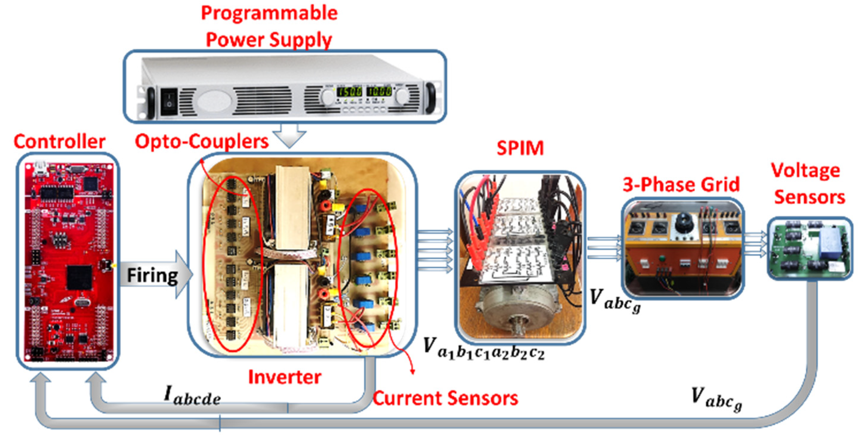
Section 5. The experimental validation is discussed in Section 6. Finally, the paper is summarized in Section 7.

2. Six-Phase-Based IOBC Connection with Grid

This section discusses the required connection of the stator winding to integrate a general SPIM-based non-isolated IOBC with the grid. When non-isolated IOBC topologies are employed, the machine acts as a single neutral (1N) SPIM; therefore, the nonavoidable circulating i 0 + , 0   current component should be properly controlled to ensure high-quality phase currents. The IOBC connection will be evaluated for the three winding layouts (D3P, A6P, and S6P) with and without winding chording employed.
For the three winding configurations of a SPIM, namely, D3P, A6P and S6P, the corresponding arbitrary spatial phase-shift angle δ between the two three-phase winding sets are 0 ° ,   30 ° , and 60 ° , respectively. The six-phase machine has three main subspaces, namely, the fundamental subspace ( α β ), secondary subspace ( x y ), and zero subspace ( 0 + 0 ). The vector space decomposition (VSD) [24] matrix that correlates the sequence components (i.e., α β ,   x y ,   and   0 + 0 ) and the phase quantity components (current or voltage) with a general arbitrary angle, δ , is given by (1).
T VSD =   1 3 × 1 cos ( 2 π 3 ) cos ( 4 π 3 ) cos δ cos ( δ + 2 π 3 ) cos ( δ + 4 π 3 ) 0 sin ( 2 π 3 ) sin ( 4 π 3 ) cos δ sin ( δ + 2 π 3 ) sin ( δ + 4 π 3 ) 1 cos ( 4 π 3 ) cos ( 2 π 3 ) cos δ cos ( δ + 2 π 3 ) cos ( δ + 4 π 3 ) 0 sin ( 4 π 3 ) sin ( 2 π 3 ) cos δ sin ( δ + 2 π 3 ) sin ( δ + 4 π 3 ) 1 1 1 1 1 0 1 0 0 0 0 0 0 1 1 1
[ i s α β i s x y i s 0 + 0 ] 6 × 1 = T VSD [ i s a 1 c 1 i s a 2 c 2 ] 6 × 1
Under propulsion mode, the fundamental subspace current components, i s α β , are exclusively utilized for torque production, while other sequence currents are controlled to zero to ensure a ripple-free torque production with high quality phase currents. On the other hand, the charging mode utilizes the secondary subspace current components, i s x y 
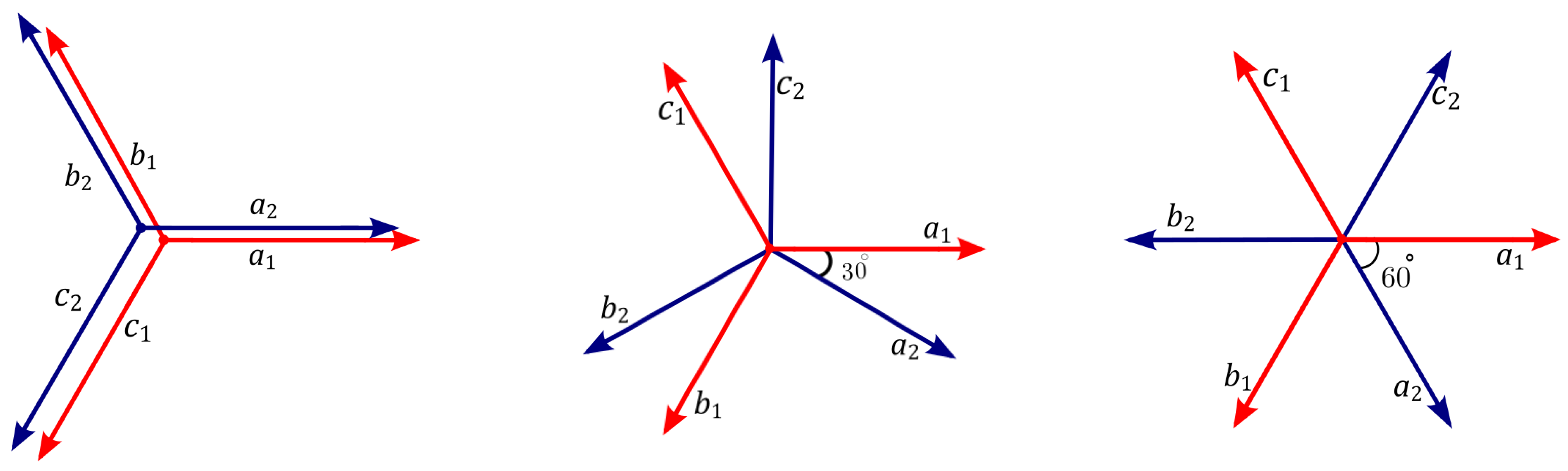
, only, while other sequence currents are controlled to zero. Under propulsion mode, and by setting the i s α β current components to I 0 and I 90 , the resultant phase currents from the inverse of (2) will yield a phase shift angle between the three-phase sets of 0 ° ,   30 ° , and for the D3P, A6P, and S6P machines, respectively, as clarified in Figure 1. Meanwhile, under charging mode, setting the i s x y current components to I 0 and I 90 results in set of phase currents with a phase shift angle between the two three-phase sets of 180 ° ,   210 ° , and 240 ° for the D3P, A6P, and S6P machines, respectively, as shown in Figure 1.
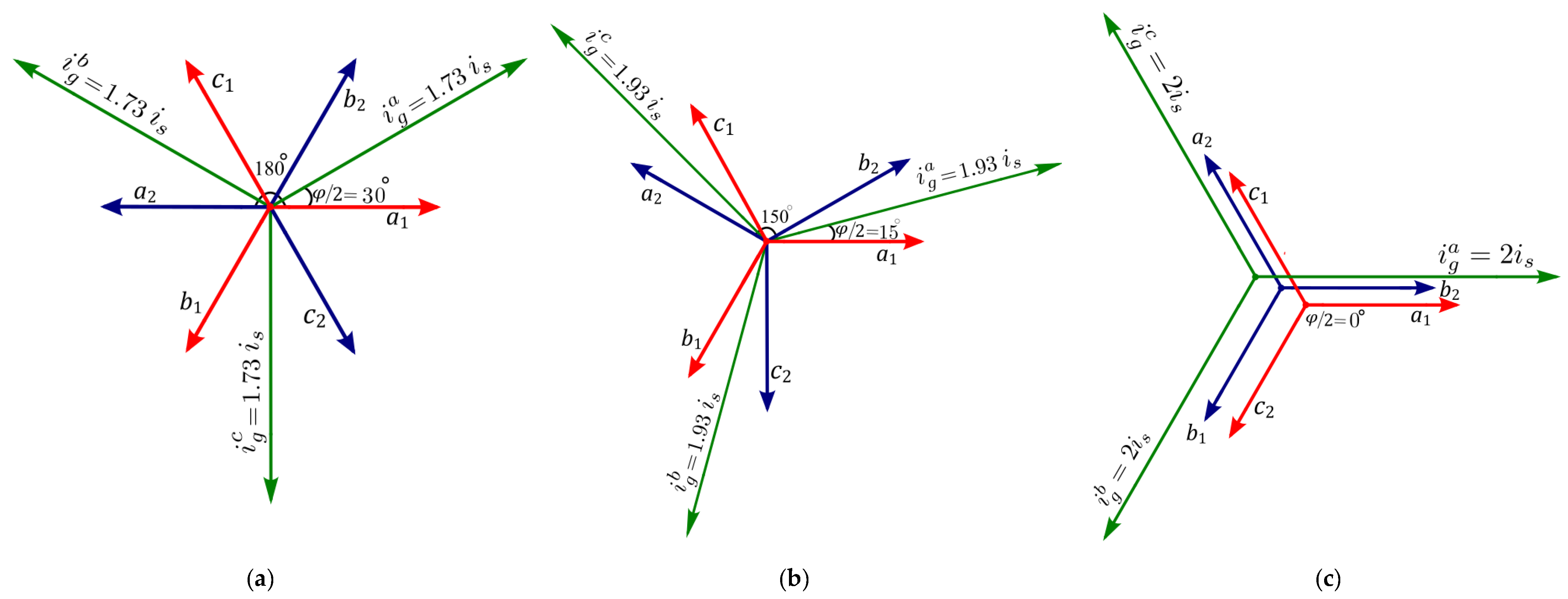
Based on the current phasors under charging given in Figure 1, the suggested external connection of the three available configurations to integrate the six-phase machine with the grid are shown in Figure 2. This connection maximizes the charging line current while nullifying the torque production inside the machine. By looking at the current phasor diagram under x y excitation shown in Figure 1, adding ( i s a 1 and i s b 2 ), ( i s b 1 and i s c 2 ), and ( i s c 1 and i s a 2 ) together result in a line current magnitude equal to 2 cos 30 ° ,   2 cos 15 ° , and 2 cos 0 ° 
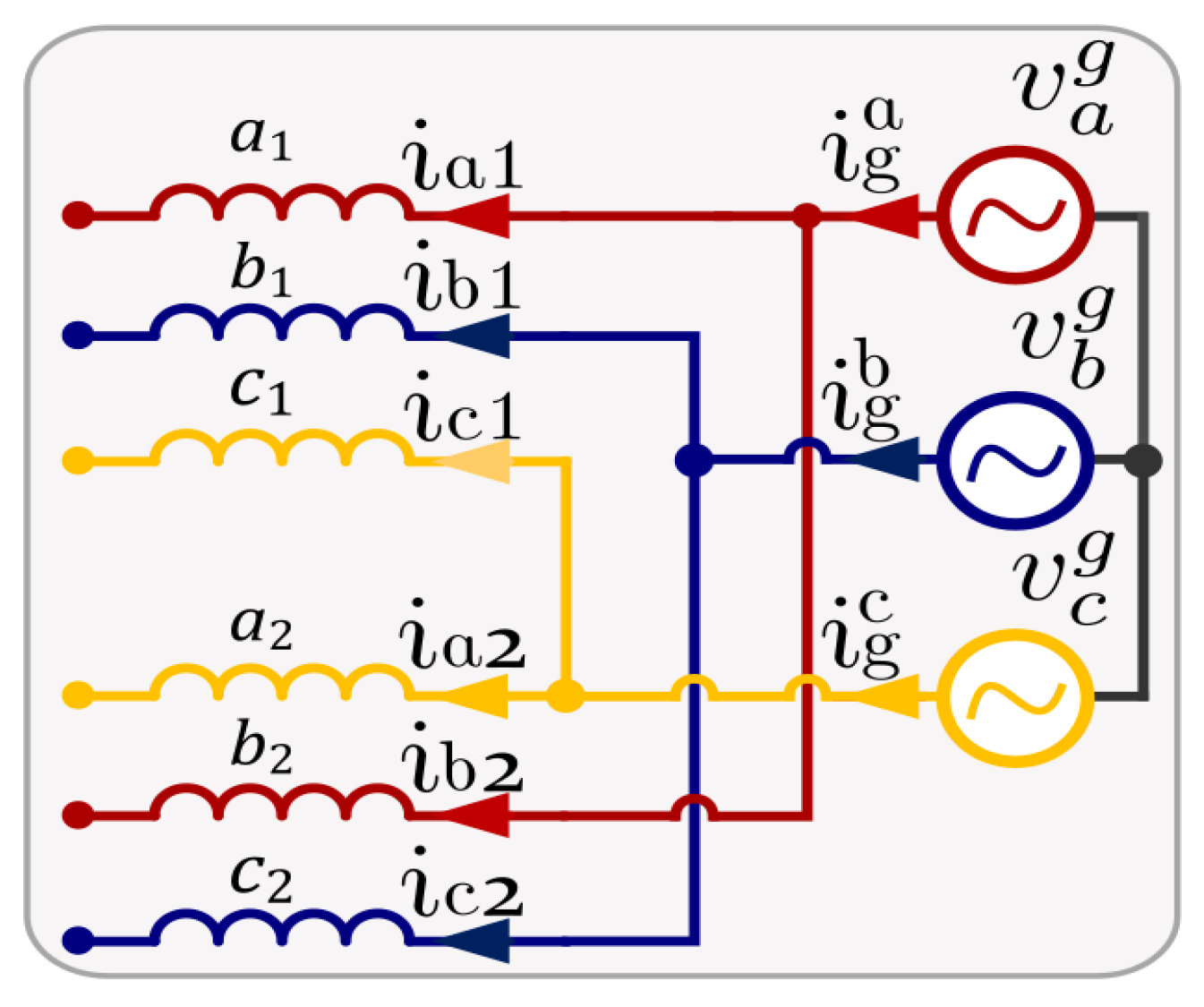
times the phase current for the three connections, respectively. Therefore, connecting the end terminals (a1 and b2), (b1 and c2), and (c1 and a2) of the six-phase stator together with the grid lines ( a g ,   b g ,   and   c g ), while exciting the x y subspace only, will maximize the charging line currents and ensure zero torque production.

3. MMF Spectra of Different Winding Layouts

In AC winding, coil chording is usually employed to obtain a high-quality flux distribution under fundamental α β excitation. In all available literature, the flux distributions under non-fundamental subspace excitations (i.e., x y and 0 + ,   0 ) were ideally assumed to be zero. This assumption was recently found to be rather ideal, especially when winding chording is applied to improve the fundamental flux [24]. In this section, the effect of winding chording on the stator MMF spectra is investigated and compared with fully pitched stators for the three available configurations. Since the IOBC control algorithm utilizes only the x y subspace in the charging process, the focus will be directed to the MMF spectra under x y excitation. A 24-slot, 4-pole stator is employed for this comparison. It has been shown in [24] that a 24-slot with 12 phases can be used to construct any of the 3 6-phase winding layouts by externally connecting certain pairs of phases in such a way as to produce 6 terminals only. In the available literature, a 5/6 coil pitch is commonly employed in practical six-phase induction machines [24], which will also be used for the chorded winding case in this study.
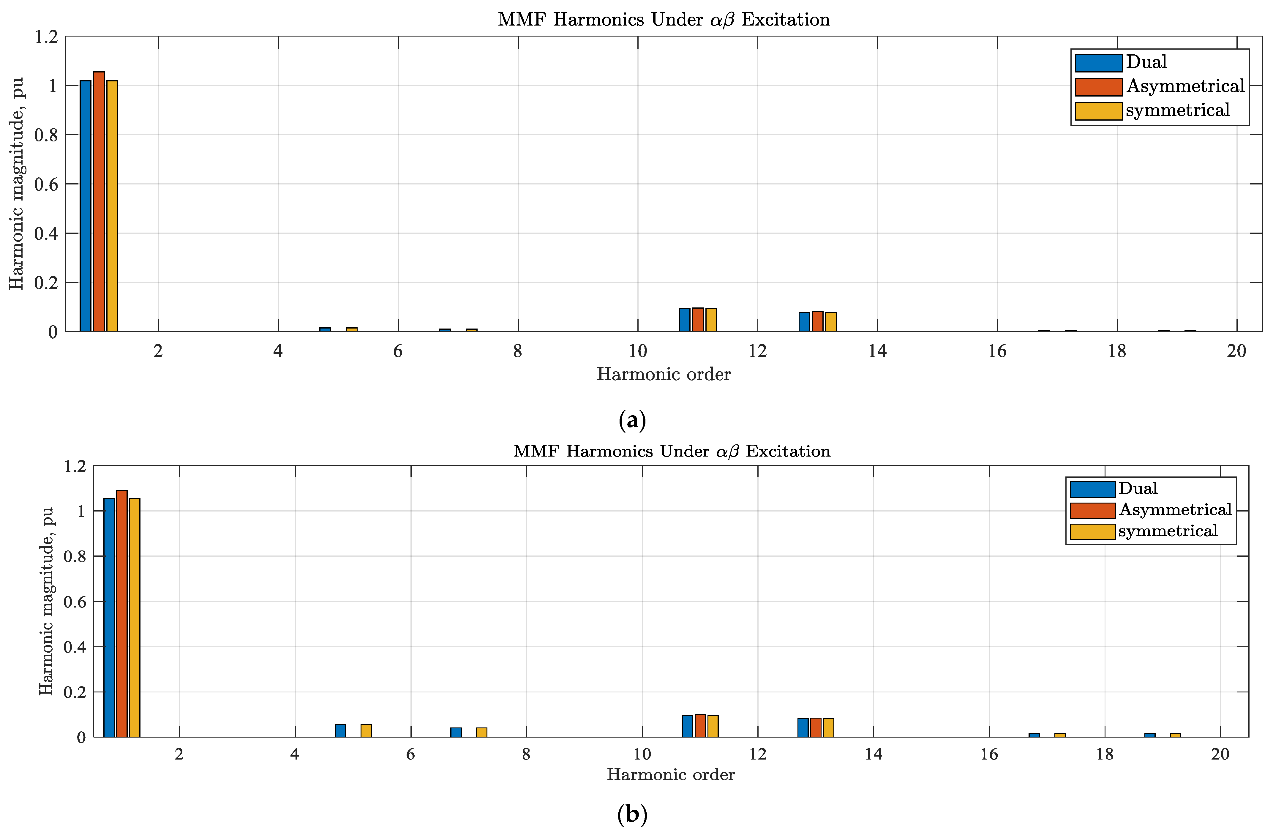
Figure 3 shows the MMF spectra under αβ excitation (propulsion mode). It is clear that chording the stator winding with one slot is essential under D3P and S6P to minimize the 5th and 7th low order space harmonics; however, it affects the fundamental component, when compared with the A6P case.
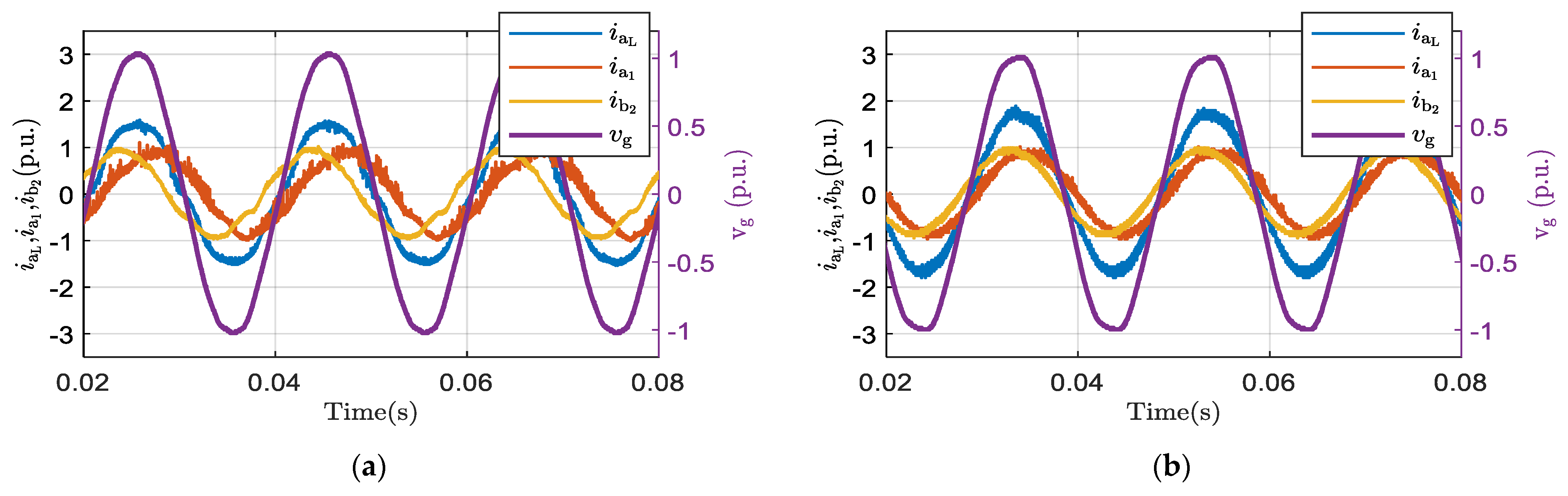
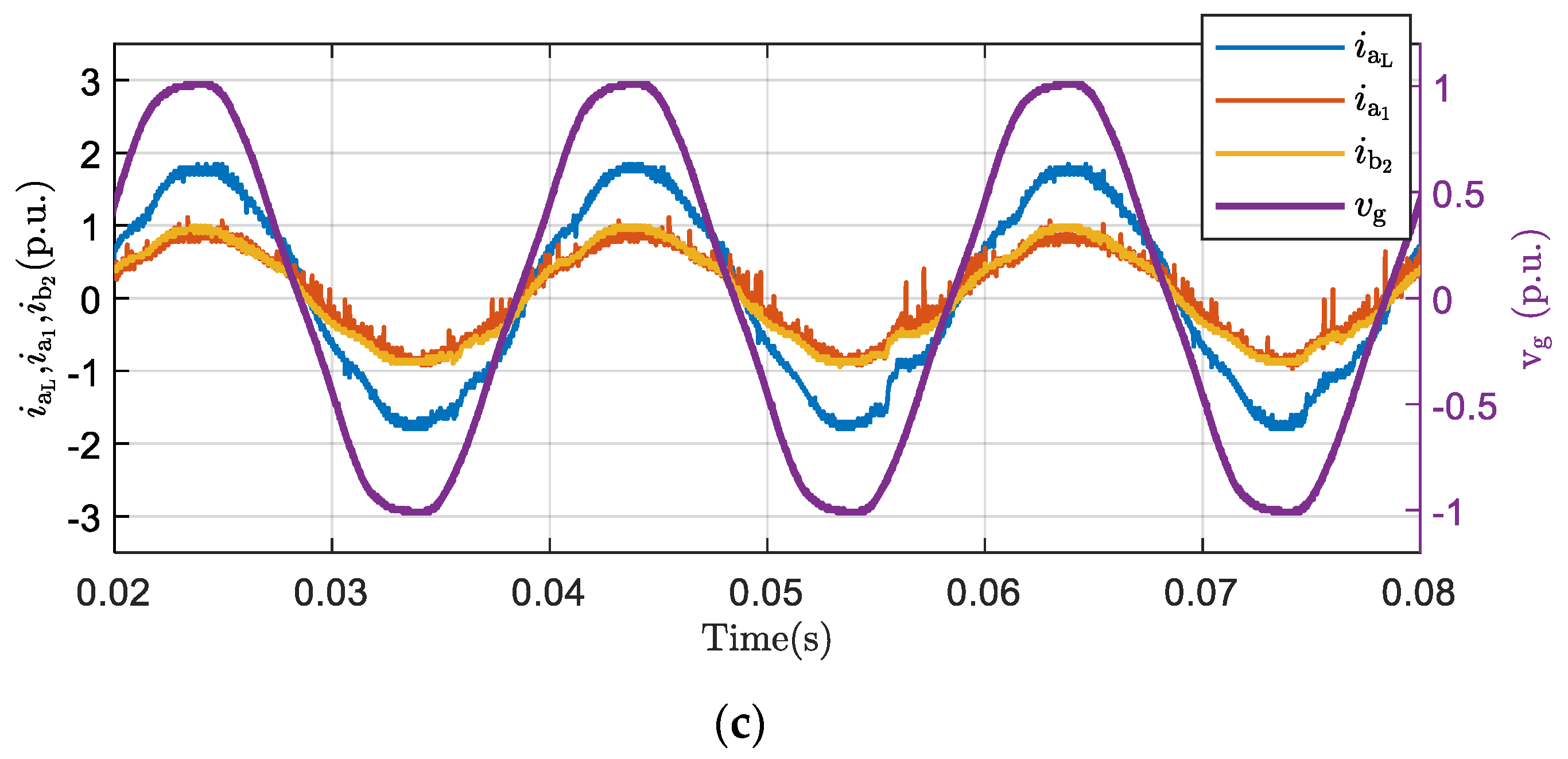
On the other hand, Figure 4 illustrates the MMF spectra under x y excitation (charging mode). It is obvious that both D3P and S6P have the same MMF spectra under chorded winding with clear, even harmonic components, indicating asymmetrical flux distribution under this excitation profile. Although these space harmonics will increase the leakage inductance of the x y subspace [24], which will improve current quality under charging, they are also expected to induce undesirable harmonics in the phase currents. On the other hand, the two winding layouts (D3P and S6P) correspond to zero magnetizing flux when fully pitch winding is employed. Figure 4 also shows the MMF spectra of an A6P stator, where the 5th and 7th harmonics represent the dominate harmonics in both chorded and un-chorded windings. Clearly, the magnitude of these two harmonics are larger under un-chorded winding, and thus, the x y inductance is expected to be larger for the un-chorded A6P machine [24].
In the available literature [
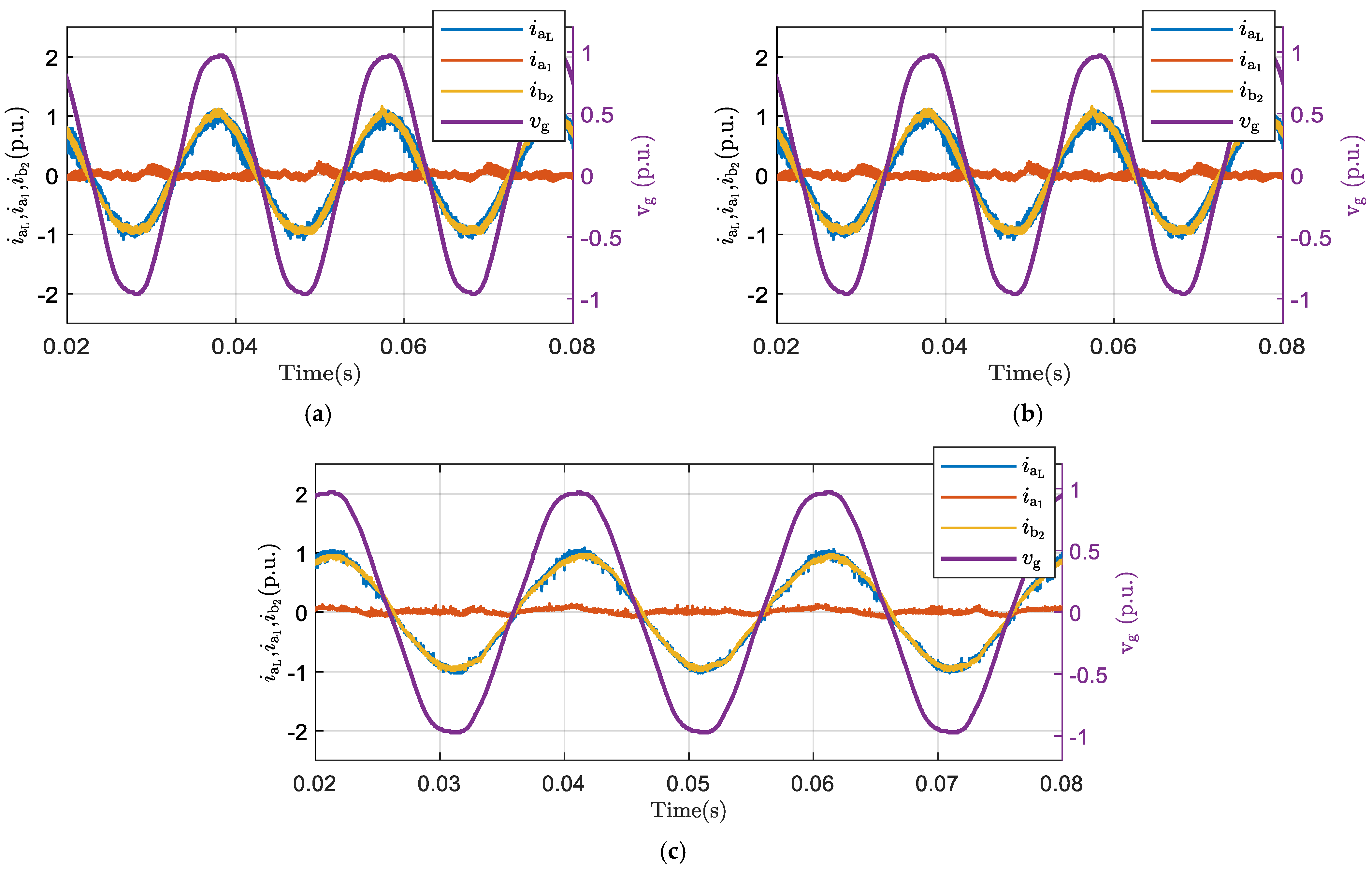
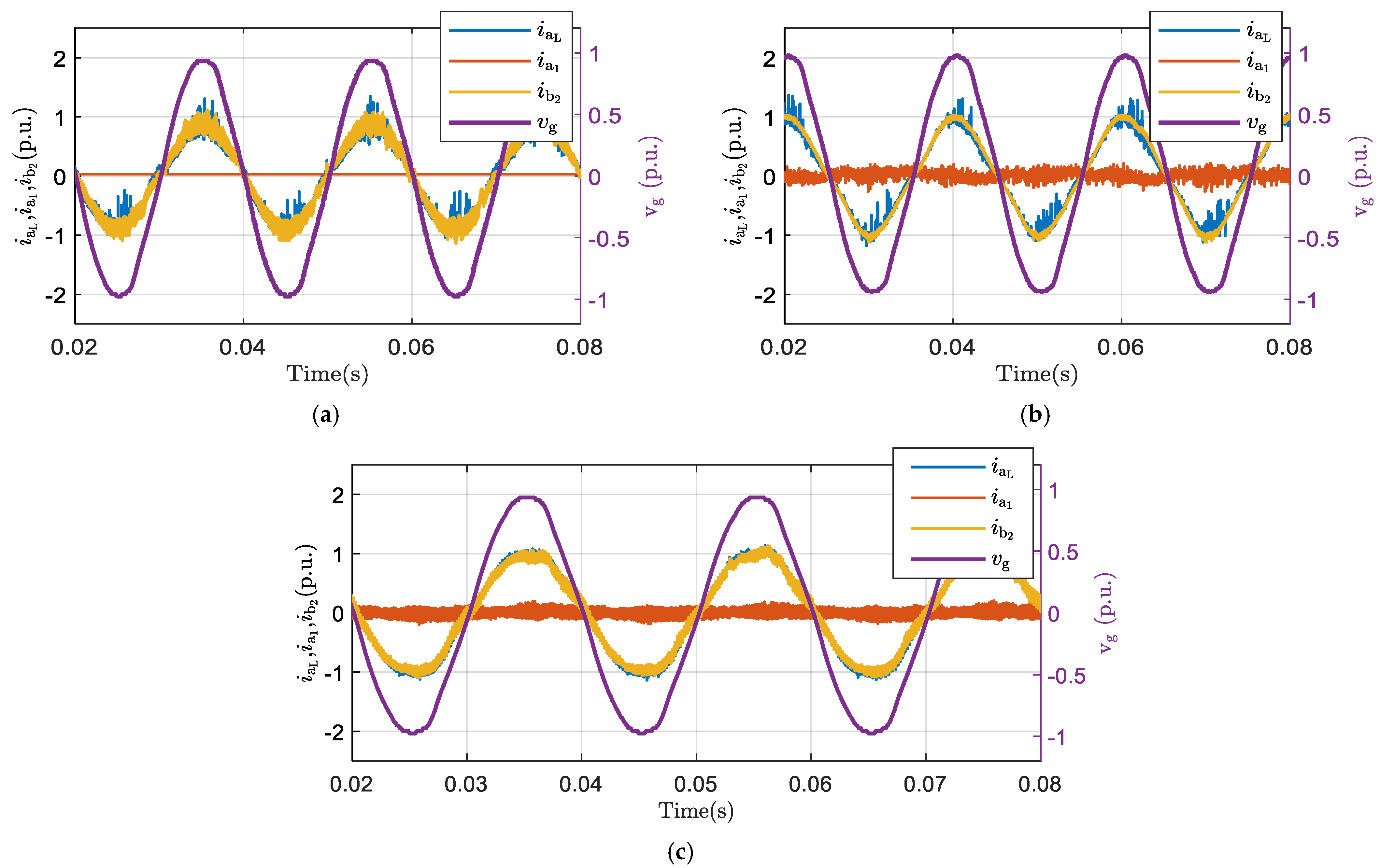
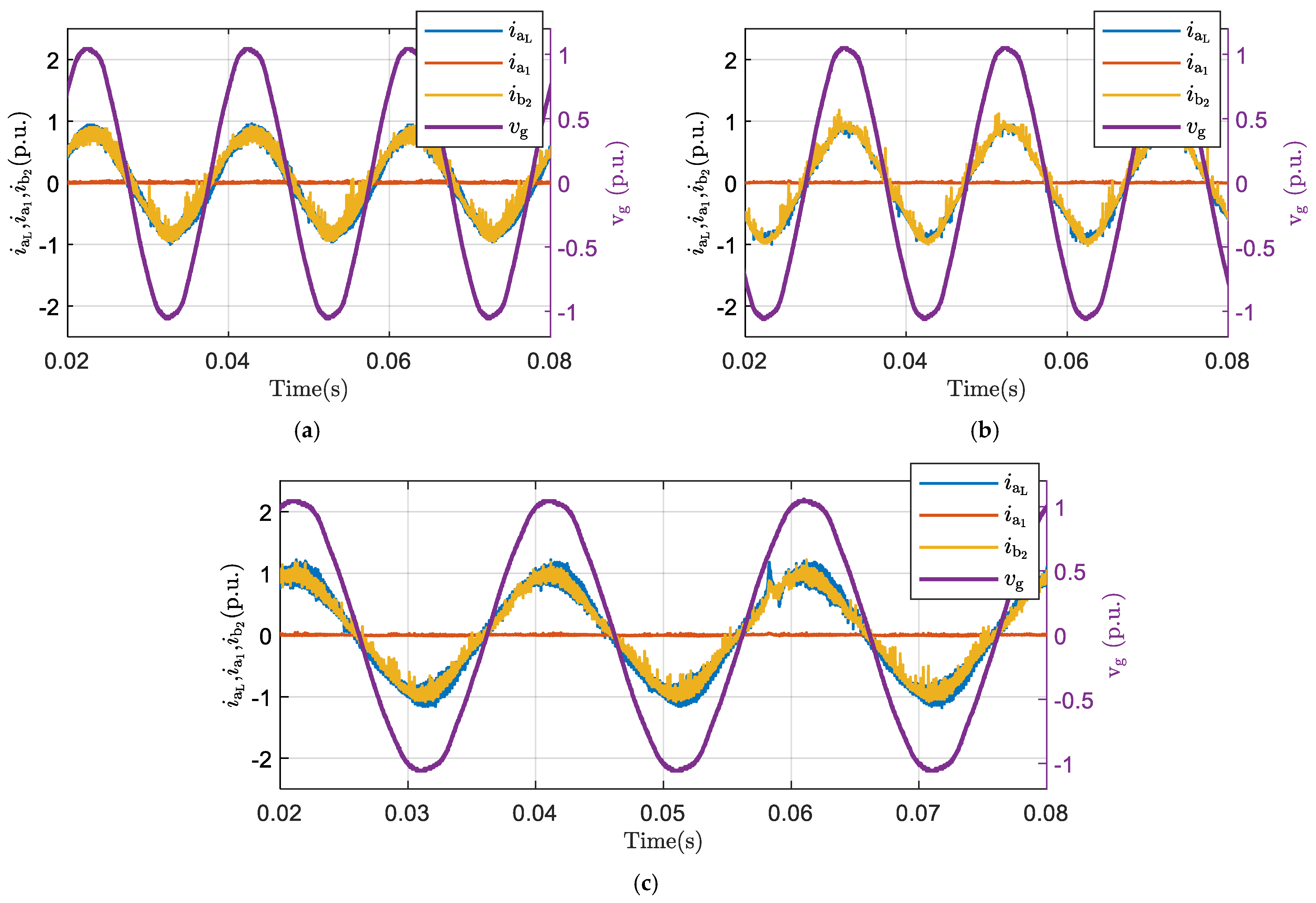
19], harmonic current compensation was proposed to suppress the induced harmonic current due to grid distortion. However, to the best of the authors’ knowledge, literature has discarded the effect of the stator phase-belt harmonics on the current quality of the IOBC-based systems, which represents the main contribution of this study. It is expected that harmonic current compensation will be essential when even space harmonics are presenting in the stator airgap, which is the case for both D3P and S6P with chorded winding. Since no even harmonics are likely to present in the A6P stator, harmonics current compensation is not essential.
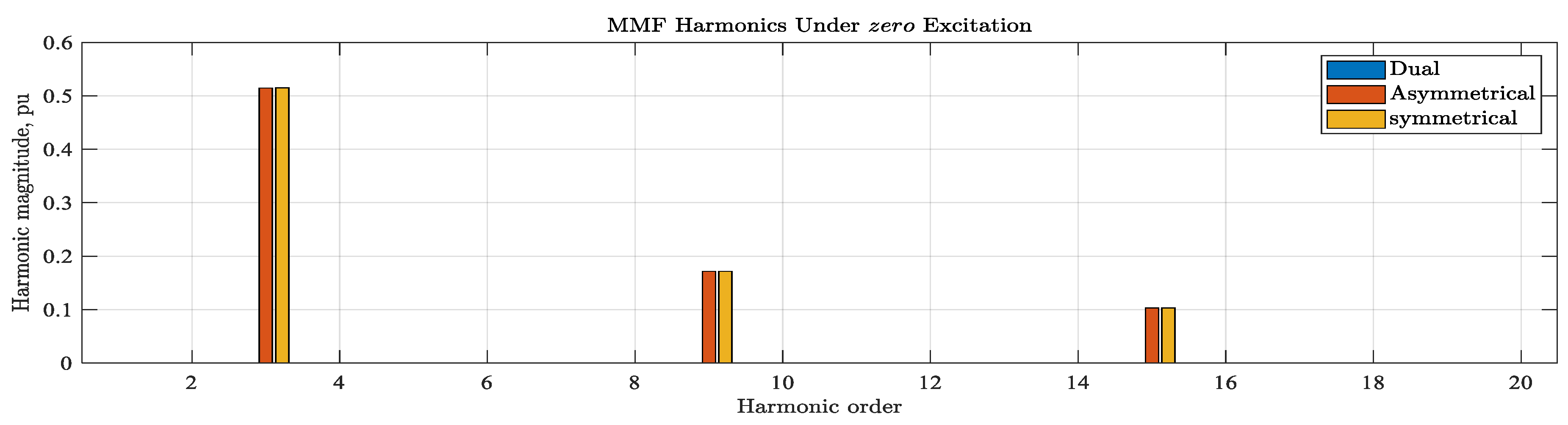
Under healthy operation, the 0 +   0 
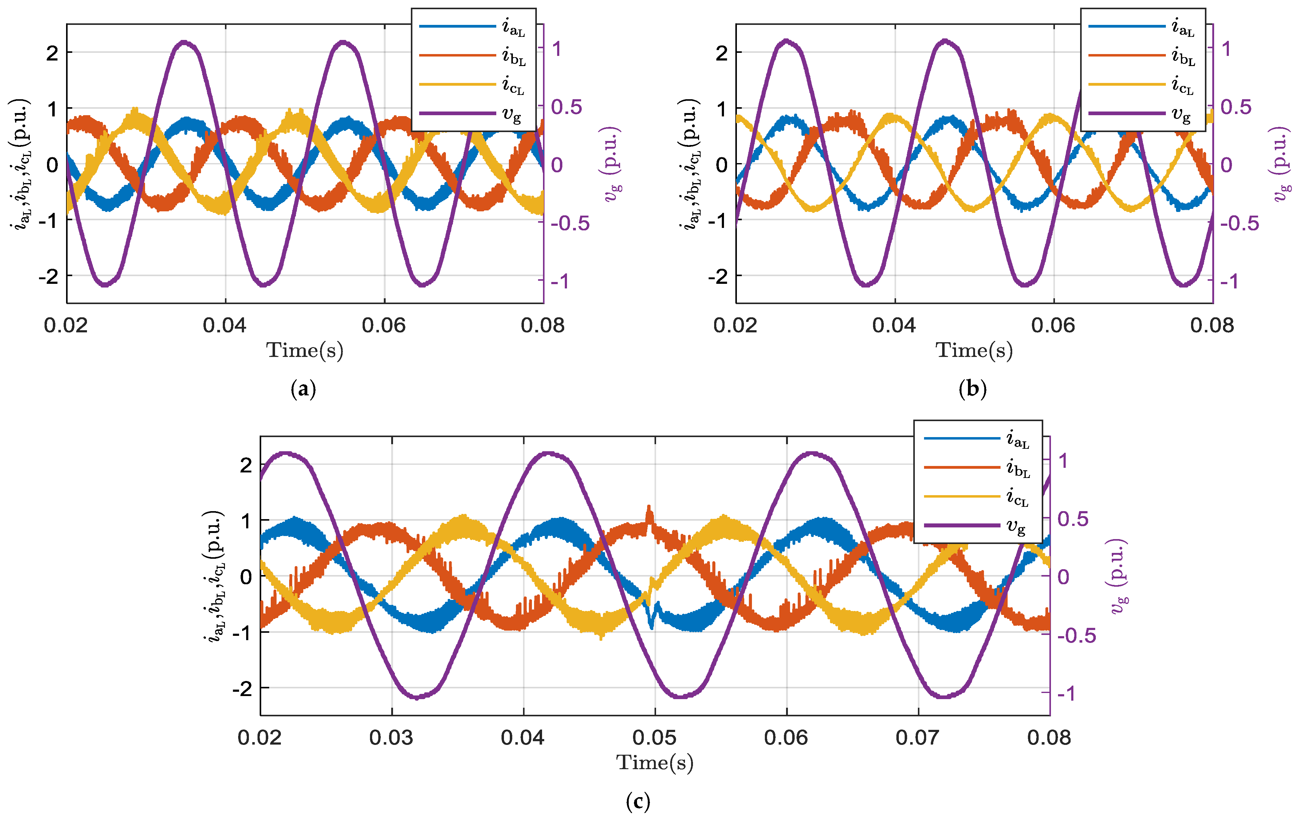
sequence components are controlled to zero, hence, their effect may be discarded. However, under postfault operation with one phase open, i 0 + 0 components are used to ensure balanced, three-phase line currents, as shown in the next section. Under this latter case, the produced space harmonics due to this subspace should be taken into consideration. Figure 5 shows the MMF spectra under 0 + ,   0 sequence excitation. Under this excitation profile, the spectra of the three winding layouts seem to be the same for both chorded/un-chorded machines.

4. Optimal Current Derivation

The well-established VSD transformation [24] has been introduced to elaborate the relation between electrical and mechanical quantities and to introduce a simple method to design basic controllers. Using the VSD transformation given by (1), the physical phase quantities f s a n c n , where f { v ,   i } , v : voltage, and i : current, are decomposed into orthogonal stationary frames as given by (2). In this section, the optimal current derivation under both healthy and 1OPF under charging mode is introduced.

4.1. Optimal Currents Derivation under Healthy Mode

Referring to Section 2, and the phasor diagram given by Figure 1 under healthy case, the optimal phase currents can be obtained using (3), where each grid line current is constrained to its corresponding related pair of phase currents, as clear from Figure 2.
[ i g a i g b i g c ] = [ 1 0 0 0 1 0 0 1 0 0 0 1 0 0 1 1 0 0 ] [ i s a 1 i s b 1 i s c 1 i s a 2 i s b 2 i s c 2 ]
Under xy excitation, the phase current vector is given by (4).
[ i s a 1 i s b 1 i s c 1 i s a 2 i s b 2 i s c 2 ] = T VSD 1 [ i s α β i s x y i s 0 + 0 ] 6 × 1 = T VSD 1 [ 0 0 I 0 ° I 90 ° 0 0 ]
From Figure 2, the grid current i g a is the summation of phase currents i s a 1 and i s b 1 . Hence, the relation between the resultant grid line current magnitude and machine phase current can be written as in (5).
| i g a | = 2 | i s a 1 | cos ( φ / 2 )
where φ is the phase angle between each pair of phase currents, which equals 60 ° ,   30 ° , and 0 ° for D3P, A6P, and S6P configurations, respectively.
From (3) and (4), the following conclusions could be made:
  • The charging current flows through the machine at zero torque production, which, in turn, eliminates the need for interlocking mechanisms during the charging process. Besides, the x y subspace currents can be considered as the exclusive charging current components, which, when controlled according to (3), balanced grid currents are obtained, assuming that there is no asymmetry in the machine windings. According to the battery specifications, the reference current is predefined, and hence, the charging grid currents are determined.
  • For a six-phase system, there is a total of five degrees of freedom. There are four reserved degrees of freedom (DOF) under charging mode ( i s α β and i s x y ) to nullify the average torque, while maintaining balanced grid currents. Hence, an extra degree of freedom ( i 0 + = i 0 ) is still available, which can be used to maintain the same control objectives under 1OPF condition.

4.2. Postfault Optimal Current Derivation under 1OPF

Under 1OPF, one degree of freedom will be lost. The single remaining degree of freedom under healthy case can, therefore, be used to ensure the same control objectives.
Assuming phase- a 1 is the faulty phase ( i s a 1 = 0 ), from the inverse of (2), one can write:
i s a 1 = i s α + i s x + i s 0 + = 0
Hence, the only condition that ensures same sequence current constraints of the healthy case is to have
i s 0 = i s 0 + = i s x
The corresponding optimal currents under 1OPF can be obtained based on (8).
[ i s a 1 i s b 1 i s c 1 i s a 2 i s b 2 i s c 2 ] = T VSD 1 [ i s α β i s x y i s 0 + 0 ] 6 × 1 = T VSD 1 [ 0 0 I 0 ° I 90 ° I 180 ° 0 ]
Hence, the optimal currents for the three cases, assuming same pre-fault conditions, are given in Table 1. Under fault conditions, some phases will exceed their rated value in case a same rated charging current is required. Hence, a suitable derating should be applied based on the phase current having maximum phase magnitude (written in bold in Table 1). The percentage derating to limit the phase having maximum current to 1 pu is also given in the same table.

5. Proposed General Current Proportional Resonant-Based Controller

In most available literature, conventional PR or synchronous PI controllers are shown to be suitable in grid connection and drive applications [25,26]. The same current controller structure can be preserved under both propulsion and charging modes through exciting the proper subspace according to the desired mode of operation. Hence, a PR current controller will be employed in this study.
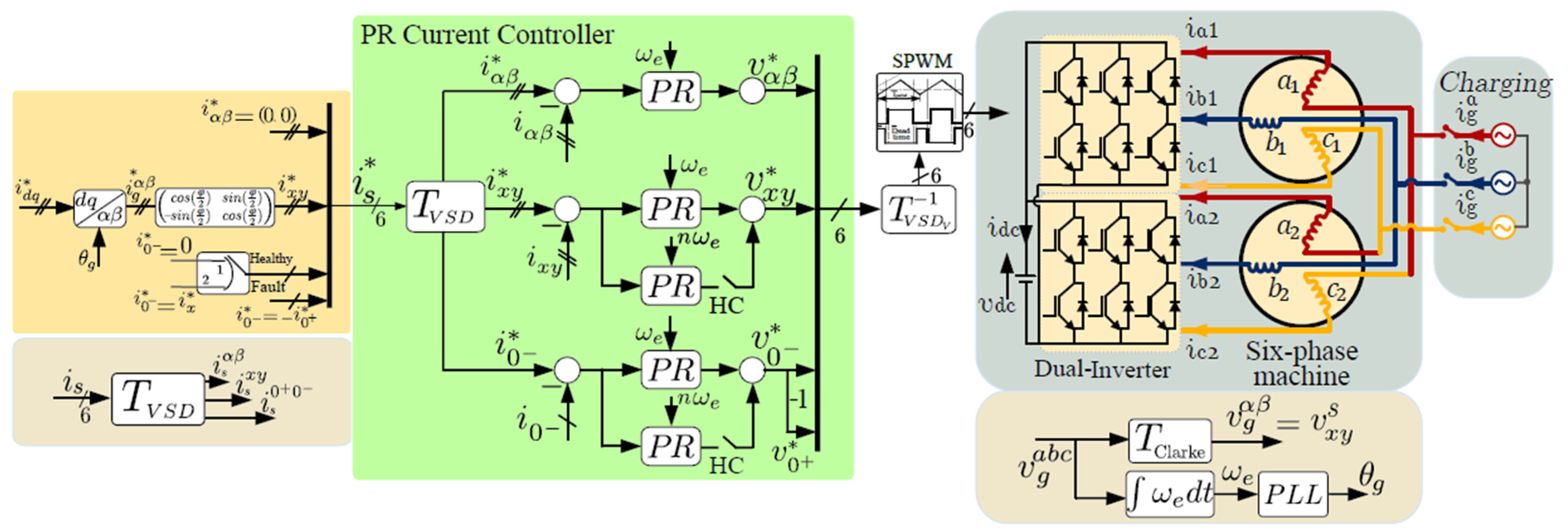
Figure 6 shows the block diagram of the proposed PR-based general current controller. Although the control algorithm is the same for all the three configurations, the harmonic compensating (HC) voltage terms depend on the machine winding layout. The proposed controller consists of three main stages. In the first stage, the reference sequence current components are derived based on the reference d q grid current components, where the reference i d * component controls the charging level, while i q * is set to zero to ensure unity power factor. The corresponding reference α β grid currents, i g α β * , are then obtained using the inverse Park’s transformation, while synchronization with the grid is simply done using a phase-locked loop. The stator x y reference currents are set equal to the α β grid currents, i g α β * . It is noteworthy from Figure 1 that any grid line current is leading the corresponding phase current of the first three-phase set by an angle φ / 2 . Therefore, in order to achieve a unity power factor charging, i g α β * should be aligned with the grid voltage by rotating the machine reference i x y * current components by the same angle, φ / 2 . The fundamental subspace sequence currents, i α β , of the SPIM are set to zero to ensure zero torque production. Finally, i 0 + 0 components are set to zero under healthy conditions, whereas the reference values of this subspace are derived based on (7) under 1OPF.
The second stage represents the PR-based current controllers, where a pair of PR controllers are used to control each subspace. Since i 0 + = i 0 , a single PR controller is used to derive the 0 +   0 sequence voltage components ( v 0 + = v 0 ). In both the x y and 0 +   0 subspaces, additional pairs of PR controllers are also used to compensate for the dominant low order harmonic current component induced in these subspaces. The harmonic compensation is enabled via HC switches shown in Figure 6. According to experimentation, the 5th and 3rd harmonics are the dominant harmonics in the x y and 0 +   0 subspaces, respectively.
In the third controller stage, the output voltage components of the PR controllers are transformed to their phase quantities using the inverse transformation given by (1). Conventional SPWM is then used to derive the six-phase inverter.
Under postfault operation, the same controller structure is used, which represents the main advantage of the proposed PR current controller. Referring to the analysis given in Section 4, only the reference value of the 0 + 0 subspace is changed to be i x * instead of zero under healthy case.
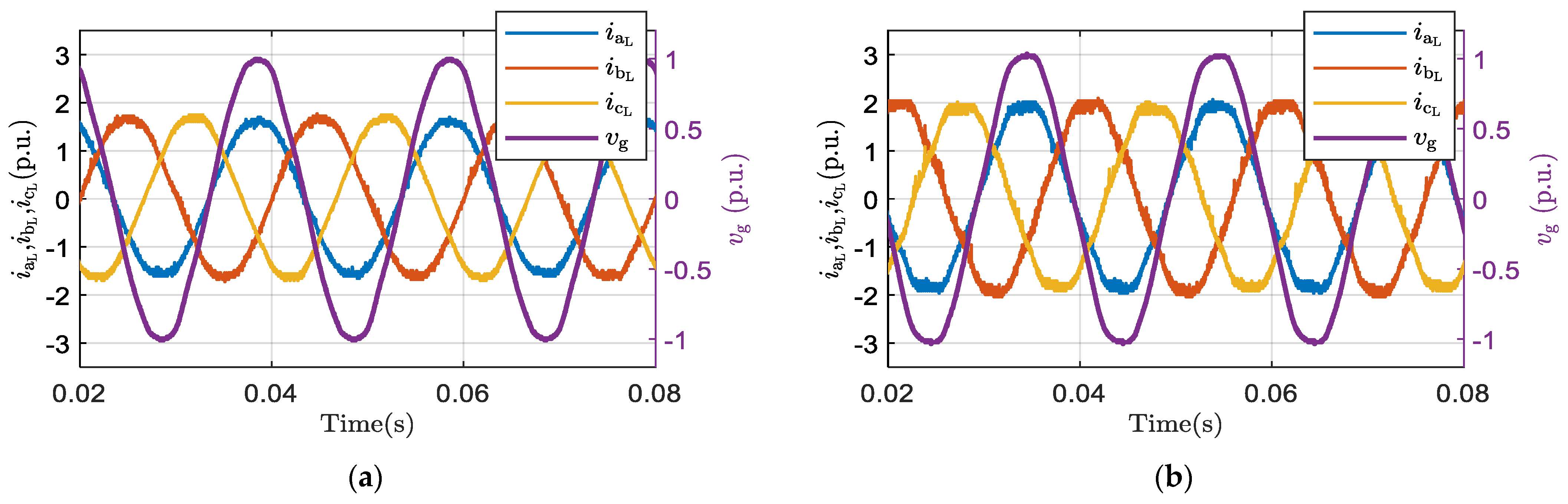
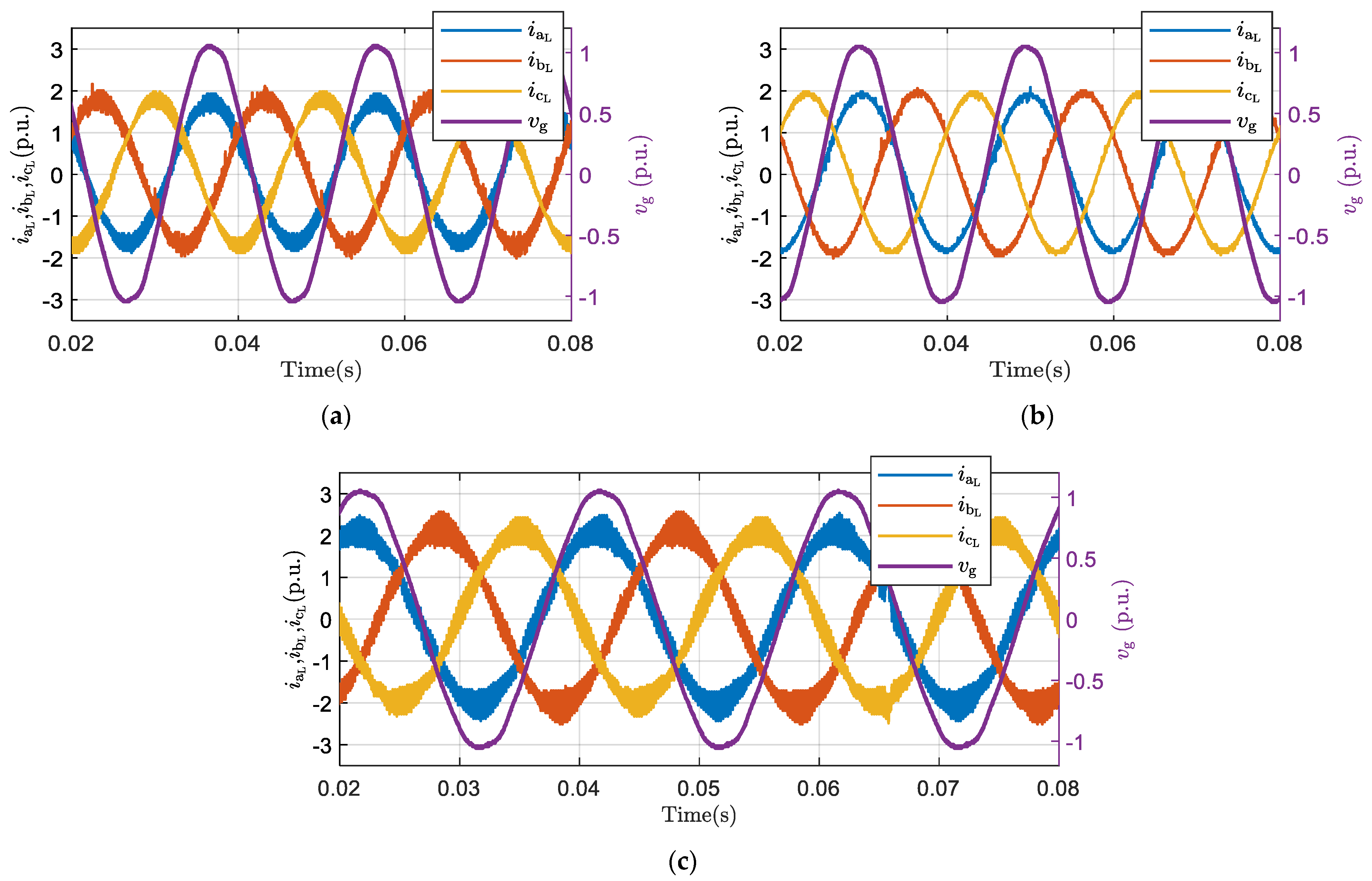
6. Experimental Evaluation

6.1. Experimental Setup

The proposed SPIM-based IOBC with different winding layouts has experimentally been validated using the test-rig shown in Figure 7. Two identical 24-slot, 4-pole off-the-shelf three-phase IMs have been rewound into chorded and un-chorded twelve-phase machines with the same rated current, as proposed in [24]. These two twelve-phase machines have been designed to be externally configured as a six-phase machine with the three possible winding configurations, namely D3P, A6P, or S6P. The first machine is wound as a double layer winding with a 5/6 coil span, while fully pitched coils are used with the second machine. The ratings of both machines are given in Table 2. Meanwhile, the measured machine parameters of both machines, which have been estimated using the technique introduced in [24], are given in Table 3. The power converter is built using a two-level six-phase inverter fed from a 300V programmable DC supply. Conventional SPWM at 5 kHz is used to derive the power converter. The controller was developed using the MATLAB/Simulink platform and deployed using Embedded Coder of Simulink into Texas Instruments F28379D Launchpad. The current feedback was carried out using six LEM LTS-25np hall effect sensors.

6.2. Experimental Results

In this section, the experimental results of the SPIM-based IOBC are investigated under both healthy and fault conditions. In all cases, the same reference charging current is set according to (5) to the rated machine phase current (4A peak). The effect of harmonic compensation on the quality of the line currents is also assessed. In the following, all currents are given in per-unit values based on machine ratings given in Table 2.

6.2.1. Healthy Case

In this case, the effect of the 0 +   0 subspace can be discarded since its reference current components are i 0 +   0 * = 0 . The need for harmonic compensation is decided based on the obtained current waveforms along with the MMF spectra given in Figure 3, Figure 4 and Figure 5.

Chorded Winding Layout

Under healthy case, the chorded winding of the SPIM-based IOBC has successfully achieved balanced three-phase gird currents with unity power factor for the three configurations, as shown in Figure 8. As previously mentioned in Section 2, the grid current magnitudes are 2 cos 30 ° ,   2 cos 15 ° , and 2 cos 0 ° times the phase current magnitude under D3P, A6P, and S6P winding layout, respectively, as shown in Figure 9.
Clearly, both D3P and S6P machines correspond to a notable distortion in the current waveforms because of the even order space harmonics under x y excitation. Fourier analysis shows a dominant 5th harmonic component in the current spectra. On the other hand, the current quality of the A6P is much better. Therefore, a harmonic compensation technique has been applied to both D3P and S6P machines to enhance the current quality, as shown in Figure 10. The THD values and the magnitude of the 5th harmonic of both phase and line currents of each configuration with and without harmonic compensation are tabulated in Table 4.

Un-Chorded Winding Layout

The same control technique has been applied to the un-chorded machine with its three possible configurations. The controller works efficiently and ensures balanced grid line currents with the same line-to-phase current magnitude ratios as in the chorded case, as shown in Figure 11 and Figure 12. Unlike the chorded machine case with either D3P or S6P connections, Figure 11 shows that the current quality of the un-chorded machine is much better since the corresponding MMF spectra have no even harmonics. On the other hand, the ripple content in the current waveform is much higher because the corresponding inductance of the x y subspace will be much lower than the chorded machine, as is clear from the machine parameters given in Table 3. The THD values of the phase and line currents as well as the magnitude of the 5th harmonic given in Table 5 also ensure that the current quality of the un-chorded machines is better. Increasing the switching frequency can significantly decrease the magnitude of current ripples. On the other hand, the A6P phase and line currents have the best quality in the un-chorded machine since it corresponds to higher x y leakage inductance.

6.2.2. Post Fault Case

When a single open phase fault is detected and cleared, the postfault algorithm is initiated. The results shown in this subsection are given under postfault operation. The maximum allowable reference charging current will differ based on winding configuration to ensure that the stator currents shall not exceed the rated currents, which is 2.8 A(rms) = 1 p.u. The required percentage derating for each configuration is obtained based on Table 1.

Chorded Winding Layout

Figure 13 shows the grid line current of the three configurations under 1OPF. Figure 14 shows the uncompensated phase currents i s a 1   and i s b 2 with the corresponding grid line current i g a for the three configurations. From Figure 5, the 0 +   0 sequence component under 1OPF adds to phase current distortion due to the induced third harmonic current component. For this fault case, the third harmonic compensation is necessarily applied to the A6P and S6P to improve the current quality, while it is not needed for the D3P case, as shown in Figure 15. The THD values and the magnitude of the 5th and 3rd harmonics of the chorded machine under 1OPF of each configuration with/without harmonic compensation are shown in Table 6. It worth mentioning that the high THD of the A6P machine is due to the small leakage inductance of the x y subspace and, hence, the ripple current content is higher than D3P and S6P machines.

Un-Chorded Winding Layout

Similar to the chorded machine under 1OPF, the optimal currents are achieved through the excitation of both x y and 0 +   0 subspaces with optimal reference currents. Figure 16 shows the line charging currents of the un-chorded SPIM-based IOBC. The experimental results of the uncompensated case are similar to the chorded case, as shown in Figure 17. When third harmonic compensation is applied, the current waveforms are given in Figure 18, while the THD values for all cases are given in Table 7.

7. Conclusions

This paper investigated the effect of winding configuration on the performance of a SPIM-based non-isolated IOBC. The required stator connections to the grid were also suggested, which ensure minimum winding reconfigurations, maximum possible line to phase current magnitude ratio, and zero torque production. The maximum charging power percentages were therefore 86.6%, 96.5%, and 100% of the rated machine power for the D3P, A6P, and S6P configurations, respectively. The effect of the winding design (chorded or un-chorded designs) on the induced space harmonics was also clarified. Upon which, the required general current controller was derived that ensures high quality current waveforms. In the case of the chorded six-phase machine, the even low order space harmonics cause a notable current distortion and induce a notable 5th order harmonic current with the D3P and S6P cases. Whereas, although employing fully pitched coils cancels out all even order MMF space harmonics, the correspondent inductance of the xy subspace is significantly reduced, which increases the ripple content in the current waveform for the same switching frequency. The MMF spectrum of the A6P machine showed that in the case of either chorded or un-chorded six-phase machines, there is odd low order space harmonics which does not affect the machine current quality. The optimal phase currents and the required percentage derating under 1OPF has also been derived for the three possible connections. Under post-fault operation, 3rd harmonic compensation was needed in the A6P and S6P cases due to circulating i 0 +   0 components. A comparative case study has been carried out based on experiments to validate the theoretical findings. Furthermore, the low order harmonic current compensation has been introduced using additional pairs of PR controllers for each harmonic component (3rd and 5th). In conclusion, the results showed that the S6P configuration with un-chorded winding represents the best compromise in terms of line current magnitude and quality.

Author Contributions

Conceptualization: M.S.A.-M., A.S. and A.S.A.-K.; methodology: M.S.A.-M., A.S. and M.S.H.; software: M.S.A.-M., A.S. and M.M.S.; validation: M.S.A.-M., A.S. and N.A.E.; formal analysis: M.S.A.-M., A.S. and A.S.A.-K.; investigation: M.S.A.-M., A.S. and A.S.A.-K.; resources: M.S.H., M.M.S. and N.A.E.; data curation: M.S.A.-M., M.M.S. and N.A.E.; writing—original draft preparation: M.S.A.-M., A.S. and A.S.A.-K.; writing—review and editing: M.S.H., M.M.S. and N.A.E.; visualization: M.S.A.-M., A.S. and N.A.E.; supervision: M.S.H., M.M.S. and N.A.E.; project administration: A.S.A.-K. and M.S.H.; funding acquisition: A.S.A.-K. and M.S.H. All authors have read and agreed to the published version of the manuscript.

Funding

This research was funded by ITIDAs ITAC collaborative funded project under the category type of advanced research projects (ARP) and grant number ARP2020.R29.7.

Acknowledgments

This work was achieved through the financial support of ITIDAs ITAC collaborative funded project under the category type of advanced research projects (ARP) and grant number ARP2020.R29.7.

Conflicts of Interest

The authors declare no conflict of interest.

References

  1. Williamson, S.S.; Rathore, A.K.; Musavi, F. Industrial electronics for electric transportation: Current state-of-the-art and future challenges. IEEE Trans. Ind. Electron. 2015, 62, 3021–3032. [Google Scholar] [CrossRef]
  2. Liu, C.; Chau, K.; Wu, D.; Gao, S. Opportunities and challenges of vehicle-to-home, vehicle-to-vehicle, and vehicle-to-grid technologies. Proc. IEEE 2013, 101, 2409–2427. [Google Scholar] [CrossRef] [Green Version]
  3. Metwly, M.Y.; Abdel-Majeed, M.S.; Abdel-Khalik, A.S.; Hamdy, R.A.; Hamad, M.S.; Ahmed, S. A review of integrated on-board EV battery chargers: Advanced topologies, recent developments and optimal selection of FSCW slot/pole combination. IEEE Access 2020, 8, 85216–85242. [Google Scholar] [CrossRef]
  4. Na, T.; Yuan, X.; Tang, J.; Zhang, Q. A review of on-board integrated electric vehicles charger and a new single-phase integrated charger. CPSS Trans. Power Electron. Appl. 2019, 4, 288–298. [Google Scholar] [CrossRef]
  5. Yilmaz, M.; Krein, P.T. Review of battery charger topologies, charging power levels, and infrastructure for plug-in electric and hybrid vehicles. IEEE Trans. Power Electron. 2012, 28, 2151–2169. [Google Scholar] [CrossRef]
  6. Kim, D.-H.; Kim, M.-J.; Lee, B.-K. An integrated battery charger with high power density and efficiency for electric vehicles. IEEE Trans. Power Electron. 2016, 32, 4553–4565. [Google Scholar] [CrossRef]
  7. Shi, C.; Tang, Y.; Khaligh, A. A three-phase integrated onboard charger for plug-in electric vehicles. IEEE Trans. Power Electron. 2017, 33, 4716–4725. [Google Scholar] [CrossRef]
  8. Grunditz, E.A.; Thiringer, T. Performance Analysis of Current BEVs Based on a Comprehensive Review of Specifications. IEEE Trans. Transp. Electrif. 2016, 2, 270–289. [Google Scholar] [CrossRef]
  9. Abdel-Khalik, A.S.; Massoud, A.; Ahmed, S. Interior permanent magnet motor-based isolated on-board integrated battery charger for electric vehicles. IET Electr. Power Appl. 2018, 12, 124–134. [Google Scholar] [CrossRef]
  10. Abdel-Majeed, M.S.; Eldeeb, H.M.; Metwly, M.Y.; Abdel-Khalik, A.S.; Hamad, M.; Hamdy, R.A.; Ahmed, S. Post-fault Operation of Onboard Integrated battery Charger via a Nine-Phase EV-Drive Train. IEEE Trans. Ind. Electron. 2020, 7, 5626–5637. [Google Scholar]
  11. Melo, V.F.M.B.; Jacobina, C.B.; Rocha, N.; Braga-Filho, E.R. Fault tolerance performance of two hybrid six-phase drive systems under single-phase open-circuit fault operation. IEEE Trans. Ind. Appl. 2019, 55, 2973–2983. [Google Scholar] [CrossRef]
  12. Subotic, I.; Bodo, N.; Levi, E. An EV Drive-Train With Integrated Fast Charging Capability. IEEE Trans. Power Electron. 2016, 31, 1461–1471. [Google Scholar] [CrossRef] [Green Version]
  13. Subotic, I.; Levi, E. An integrated battery charger for EVs based on a symmetrical six-phase machine. In Proceedings of the 2014 IEEE 23rd International Symposium on Industrial Electronics (ISIE), Istanbul, Turkey, 1–4 June 2014; pp. 2074–2079. [Google Scholar]
  14. Abdel-Khalik, A.S.; Massoud, A.; Ahmed, S. Standard Three-Phase Stator Frames for Multiphase Machines of Prime-Phase Order: Optimal Selection of Slot/Pole Combination. IEEE Access 2019, 7, 78239–78259. [Google Scholar] [CrossRef]
  15. Paredes, J.; Prieto, B.; Satrústegui, M.; Elósegui, I.; González, P. Improving the Performance of a 1-MW Induction Machine by Optimally Shifting From a Three-Phase to a Six-Phase Machine Design by Rearranging the Coil Connections. IEEE Trans. Ind. Electron. 2021, 68, 1035–1045. [Google Scholar] [CrossRef]
  16. Shawier, A.; Habib, A.; Mamdouh, M.; Abdel-Khalik, A.S.; Ahmed, K.H. Assessment of predictive current control of six-phase induction motor with different winding configurations. IEEE Access 2021, 9, 81125–81138. [Google Scholar] [CrossRef]
  17. Abdel-Khalik, A.S.; Massoud, A.M.; Ahmed, S. An Improved Torque Density Pseudo Six-Phase Induction Machine Using a Quadruple Three-Phase Stator Winding. IEEE Trans. Ind. Electron. 2020, 67, 1855–1866. [Google Scholar] [CrossRef]
  18. Subotic, I.; Levi, E.; Jones, M.; Graovac, D. An Integrated Battery Charger for EVs Based on an Asymmetrical Six-Phase Machine. In Proceedings of the IECON 2013-39th Annual Conference of the IEEE Industrial Electronics Society, Vienna, Austria, 10–13 November 2013; pp. 7244–7249. [Google Scholar]
  19. Subotic, I.; Bodo, N.; Levi, E. Integration of six-phase EV drivetrains into battery charging process with direct grid connection. IEEE Trans. Energy Convers. 2017, 32, 1012–1022. [Google Scholar] [CrossRef] [Green Version]
  20. Diab, M.S.; Elserougi, A.A.; Abdel-Khalik, A.S.; Massoud, A.M.; Ahmed, S. A nine-switch-converter-based integrated motor drive and battery charger system for EVs using symmetrical six-phase machines. IEEE Trans. Ind. Electron. 2016, 63, 5326–5335. [Google Scholar] [CrossRef]
  21. Liu, X.; Yu, F.; Mao, J.; Yang, H. Pre-and post-fault operations of six-phase electric-drive-reconstructed onboard charger for electric vehicles. IEEE Trans. Transp. Electrif. 2021. [Google Scholar] [CrossRef]
  22. Munim, W.N.W.A.; Duran, M.J.; Che, H.S.; Bermudez, M.; Gonzalez-Prieto, I.; Abd Rahim, N. A unified analysis of the fault tolerance capability in six-phase induction motor drives. IEEE Trans. Power Electron. 2016, 32, 7824–7836. [Google Scholar] [CrossRef]
  23. Garcia, D.F.V.; Taylor, J.; Mohamadian, M.; Luedtke, D.; Emadi, A.; Bilgin, B. A Comparative Analysis for Six-Phase Motor Configurations; 0148-7191; SAE Technical Paper; SAE International: Warrendale, PA, USA, 2020. [Google Scholar]
  24. Abdel-Khalik, A.S.; Abdel-Majeed, M.S.; Ahmed, S. Effect of winding configuration on six-phase induction machine parameters and performance. IEEE Access 2020, 8, 223009–223020. [Google Scholar] [CrossRef]
  25. Vidal, A.; Freijedo, F.D.; Yepes, A.G.; Fernandez-Comesana, P.; Malvar, J.; López, Ó.; Doval-Gandoy, J. Assessment and optimization of the transient response of proportional-resonant current controllers for distributed power generation systems. IEEE Trans. Ind. Electron. 2012, 60, 1367–1383. [Google Scholar] [CrossRef]
  26. Yepes, A.G.; Vidal, A.; Malvar, J.; López, O.; Doval-Gandoy, J. Tuning method aimed at optimized settling time and overshoot for synchronous proportional-integral current control in electric machines. IEEE Trans. Power Electron. 2013, 29, 3041–3054. [Google Scholar] [CrossRef]
Figure 1. Phase and line currents of SPIM for all three types of SPIM (a) D3P, (b) A6P, and (c) S6P, under propulsion mode (upper plots) and charging mode (lower plots).
Sustainability 14 01088 g001aSustainability 14 01088 g001b
Figure 2. Proposed connection for SPIM based IOBC.
Sustainability 14 01088 g002
Figure 3. MMF harmonic spectra for different SPIM connections under α β excitation. (a) Chorded winding. (b) Un-chorded winding.
Sustainability 14 01088 g003
Figure 4. MMF harmonic spectra for different SPIM connections under x y excitation. (a) Chorded winding. (b) Un-chorded winding.
Sustainability 14 01088 g004
Figure 5. MMF harmonic spectra for different SPIM connections under z e r o s e q u e n c e excitation.
Sustainability 14 01088 g005
Figure 6. Proposed current controller of the six-phase-based non-isolated IOBC.
Sustainability 14 01088 g006
Figure 7. Experimental six-phase setup.
Sustainability 14 01088 g007
Figure 8. The grid line currents of chorded SPIM-based IOBC under healthy case without harmonic compensation. (a) D3P. (b) A6P. (c) S6P.
Sustainability 14 01088 g008
Figure 9. The phase to line current relation of chorded SPIM-based IOBC under healthy case without harmonic compensation. (a) D3P. (b) A6P. (c) S6P.
Sustainability 14 01088 g009aSustainability 14 01088 g009b
Figure 10. The grid line currents of chorded SPIM-based IOBC under healthy case with harmonic compensation. (a) D3P. (b) S6P.
Sustainability 14 01088 g010
Figure 11. The grid line currents of un-chorded SPIM-based IOBC under healthy case. (a) D3P. (b) A6P. (c) S6P.
Sustainability 14 01088 g011
Figure 12. The phase and line current of un-chorded SPIM-based IOBC under healthy case. (a) D3P. (b) A6P. (c) S6P.
Sustainability 14 01088 g012aSustainability 14 01088 g012b
Figure 13. The grid line currents of chorded SPIM-based IOBC under 1OPF case without harmonic compensation. (a) D3P. (b) A6P. (c) S6P.
Sustainability 14 01088 g013
Figure 14. The phase and line currents of chorded SPIM-based IOBC under 1OPF case without harmonic compensation. (a) D3P. (b) A6P. (c) S6P.
Sustainability 14 01088 g014
Figure 15. The phase and line currents of chorded SPIM-based IOBC under 1OPF case with harmonic compensation. (a) D3P. (b) A6P. (c) S6P.
Sustainability 14 01088 g015
Figure 16. The grid line currents of un-chorded SPIM-based IOBC under 1OPF case. (a) D3P. (b) A6P. (c) S6P.
Sustainability 14 01088 g016
Figure 17. The phase and line currents of un-chorded SPIM-based IOBC under 1OPF case without harmonic compensation. (a) D3P. (b) A6P. (c) S6P.
Sustainability 14 01088 g017
Figure 18. The phase and line currents of un-chorded SPIM-based IOBC under 1OPF case with harmonic compensation. (a) D3P. (b) A6P. (c) S6P.
Sustainability 14 01088 g018
Table 1. Optimal currents and derating percentages of different SPIM connections under 1OPF.
ConnectionD3PA6PS6P
Optimal currents [ i s a 1 i s b 1 i s c 1 i s a 2 i s b 2 i s c 2 ] [ 0 1.7321 150 ° 1.7321 150 ° 0 1.7321 30 ° 1.7321 30 ° ] [ 0 1.7321 150 ° 1.7321 150 ° 0.5176 75 ° 1.9319 15 ° 1.4142 45 ° ] [ 0 1.7321 150 ° 1.7321 150 ° 1 60 ° 2 0 ° 1 60 ° ]
Percentage derating (%)42.348.250
Table 2. Machine Ratings.
ParameterValue
Rated RMS phase Voltage (V)110 V
Rated Power (kW)1.1
Rated RMS phase current (A)2.8
Rated frequency (Hz)50
No. of poles4
Rated speed (RPM)1400
Table 3. Machine Parameters.
ParameterChordedUn-Chorded
D3PA6PS6PD3PA6PS6P
Stator resistance4.18 Ω4.18 Ω4.18 Ω5 Ω5 Ω5 Ω
Rotor resistance3.46 Ω3.67 Ω3.46 Ω2.9 Ω3.1 Ω2.9 Ω
α β stator leakage inductance9.1 mH12 mH9.1 mH10 mH9.6 mH10 mH
α β rotor leakage inductance19.1 mH16.7 mH19.1 mH21 mH22.5 mH21 mH
α β magnetizing inductance254 mH247 mH260 mH270 mH304 mH284 mH
x y stator leakage inductance11.8 mH7.5 mH11.8 mH4.44 mH25.5 mH4.52 mH
Zero sequence resistance5.5 Ω13.7 Ω5.6 Ω5.6 Ω6.7 Ω6.86 Ω
Zero sequence inductance18.2 mH23.5 mH26.2 mH4.74 mH26.46 mH4.78 mH
Table 4. THD values of chorded SPIM-based IOBC under healthy operation.
THDWithout Harmonic Compensation With Harmonic Compensation
D3PA6PS6PD3PS6P
THD Line current5.01%3.07%5.05%4.07%3.93%
5th Har Mag.3.89%0.23%3.71%0.15%0.25%
THD Phase current6.24%4.6%5.6%5%5.17%
5th Har Mag.3.87%1.25%3.48%2%0.38%
Table 5. THD values of un-chorded SPIM-based IOBC under healthy operation.
THDWithout Harmonic Compensation
D3PA6PS6P
THD Line current7.69%2.30%7.26%
5th Har. Mag.0.38%0.26%0.63%
THD Phase current8.42%3.25%9.97%
5th Har. Mag.0.29%0.36%0.36%
Table 6. THD values of chorded SPIM-based IOBC under postfault operation (1OPF).
THD Without Harmonic CompensationWith Harmonic Compensation
D3PA6PS6PD3PA6PS6P
THD Line current5.64%10.67%5.27%5.95%8.8%5.14%
5th Har. Mag.4.44%0.21%3.02%0.82%0.31%0.14%
3rd Har Mag.1.56%2.84%2.14%1.56%1.1%1.56%
THD Phase current6.13%9.59%8.33%5.95%8.98%5.17%
5th Har Mag.3.12%1.33%4.69%0.82%0.31%0.38%
3rd Har Mag.1.56%3.39%3.62%1.56%2.03%0.3%
Table 7. THD values of un-chorded SPIM based IOBC under postfault operation (1OPF).
THD Without Harmonic CompensationWith Harmonic Compensation
D3PA6PS6PD3PA6PS6P
THD Line current11.13%4.95%11.86%7.13%2.91%7.57%
5th Har Mag.0.63%0.95%0.36%0.63%0.95%0.36%
3rd Har Mag.1.89%0.7%1.90%1.89%0.7%1.90%
THD Phase current7.64%5.64%10.01%7.64%3.23%8.68%
5th Har Mag.0.18%1.64%0.36%0.18%1.64%0.36%
3rd Har Mag.1.89%6.5%5.98%1.89%1.13%1.20%
Publisher’s Note: MDPI stays neutral with regard to jurisdictional claims in published maps and institutional affiliations.

