Article

Performance Investigation of Switched Reluctance Motor Driven by Quasi-Z-Source Integrated Multiport Converter with Different Switching Algorithms

1
Aswan Power Electronics Applications Research Center (APEARC), Faculty of Engineering, Aswan University, Aswan 81542, Egypt
2
School of Electrical and Power Engineering, China University of Mining and Technology, Xuzhou 221116, China
*
Author to whom correspondence should be addressed.
Sustainability 2021, 13(17), 9517; https://doi.org/10.3390/su13179517
Submission received: 16 June 2021 / Revised: 5 August 2021 / Accepted: 18 August 2021 / Published: 24 August 2021

Abstract

:
Switched reluctance machines (SRMs) have received increasing attention for their many potential uses, such as for wind power and electric vehicle (EV) drive systems. The Quasi-Z-source Integrated Multiport Converter (QZIMPC) was recently introduced to improve the reliability of the SRM driver through small capacitance values. It is not possible, however, to simultaneously energize and deenergize two SRM phases in QZIMPC. This phenomenon can significantly increase the commutation period which, in turn, degrades the performance of SRM; in addition, this causes high-voltage ripples on the converter’s capacitors. Two switching algorithms are introduced and applied in this paper, and their performance with SRM is investigated in terms of torque ripple and peak phase current. The algorithms are based on prioritizing the control command in the on-going and off-going phases to fulfill the required load torque, as well as to accelerate the commutation process where possible. This is achieved without the interference of high-level controllers, which include speed controllers and/or torque ripple minimization. Through the simulation results, a comparison between the two switching algorithms is presented to determine their potential to improve the SRM drive system’s performance.

1. Introduction

Switched reluctance machines (SRMs) are gaining attention for their utility in many applications, including renewable energy systems such as wind, wave and tidal energy systems, and electric vehicle (EV) drive systems [1,2,3,4]. This is due to their simple structure: both the stator and rotor are formed from salient poles, and neither permanent magnets nor conductors are required on the rotor. Furthermore, SRMs use the concentrated type of stator winding. This simple structure offers many advantages, including a low manufacturing cost, rapid acceleration, robust operation under high-speed and high-temperature conditions, and fault-tolerant capability [3,4,5,6].
The torque produced by the SRM phase is expressed in Equation (1) [3],
T p h = 1 2 i p h 2 d L θ d θ
where iph is the phase current, L is the phase inductance, and θ is the stator phase angle with respect to the rotor. According to (1), the phase torque is positive during the positive slope of the phase inductance, negative during the negative slope of inductance, and zero during the constant inductance intervals. Therefore, to avoid motor operation under negative torque production, the off-going phase should be completely demagnetized as fast as possible before reaching the inductance negative slope region.
The operation of SRM phases consists of three modes: magnetization, regenerative demagnetization, and freewheeling modes. Ideally, each phase should conduct a rectangular current waveform, such that when one phase is demagnetized, excitation in another phase begins. However, due to the non-linear inductance of SRM phases and the rotational back-induced Electromotive Force (EMF), phase currents do not instantaneously rise or decay [3]. This commutation behavior is illustrated in Figure 1.
Finite element method (FEM) simulations are usually adopted to analyze and optimize the SRM performance [7]. Figure 2a,b show two typical characteristics of SRM. These characteristics are: (1) Variation in inductance with the rotor position at different current values. These figures illustrate the effect of saturation on the inductance; this becomes more significant when the current increases. (2) The torque variation with the rotor position at different current values. The deformation is apparent in the torque profile due to the non-linearity of the phase inductances. This deformation implies a higher torque ripple under constant current profiles.
In addition, due to the large amount of energy transfer between the input power source and SRM during commutation, a large filter capacitor is necessary to balance the difference in instantaneous power. Long periods of commutation can also significantly limit the speed range of SRM and decrease its torque productivity [8,9,10,11].
To reduce the torque ripple, current overlapping of two SRM phases is usually adopted [12,13]. This overlapping can be achieved through the simultaneous operation of two adjacent SRM phases using one of the following options:
  • Simultaneous magnetization of the on-going phase and regenerative demagnetization for the off-going phase.
  • Simultaneous magnetization of the on-going phase and freewheeling of the off-going phase.
The first option is more desirable, as it can significantly reduce the commutation period; this becomes more critical at high speeds to produce the load torque required.
To shape the SRM phase currents properly, the SRM drive system consists of a power converter and a suitable control algorithm to control the phase current amount along with the rise and fall times; a schematic for an SRM-based drive system is shown in Figure 3. Thus, the overall performance of the SRM drive system is particularly affected by the power converter topologies. Asymmetric H-bridge converters are usually adopted in SRM drive systems [3,14]. This topology requires 2 × n switches and 2 × n diodes for a n-phase SRM. The high number of semiconductors increases the overall cost and reduces drive efficiency. While shared switch converters can offer a low number of semiconductors, they are only applicable for SRM with an even number of phases [15].
Star-connected converter topology, shown in Figure 4a, can reduce the number of switches and diodes to n + 1 of each. In addition, the smaller quantity of wires decreases the cost of maintenance and manufacturing [16,17]. In this converter, an asymmetrical leg is connected to each SRM phase. One common asymmetrical leg is also connected to the star connection point of the inverter. Sc and Dc are the switch and diode of this common leg, respectively. For an arbitrary phase i, magnetization can be achieved through Sc and Si; on the other hand, demagnetization can be achieved through Di and Dc. For freewheeling, both (Sc and Di) or (Si and Dc) can be utilized to realize this mode. Although this configuration uses a low number of semiconductors and is applicable for use with an SRM having any number of phases, it has the following limitations:
  • The speed range is limited because simultaneous magnetization and demagnetization of two SRM phases cannot be realized.
  • It cannot offer a boosting gain; thus, magnetization and demagnetization are achieved with voltages equal to the source voltage. Therefore, it cannot offer fast magnetization and demagnetization, resulting in low torque productivity from SRM.
  • A high decoupling capacitor is required to decouple the difference in the instantaneous power. This represents an obstacle to the overall reliability and the commercial competitiveness of SRM drives.
To overcome these limitations, number of converters were derived based on a star-connected configuration, as follows:
  • C–dump converters were introduced to offer boosting voltage capability [18]. In this converter, the capacitor voltage is usually regulated to offer double the input voltage during demagnetization. Although this offers fast demagnetization for the off-going phase, the torque productivity is still limited due to the low voltage offered during magnetization of the on-going phase.
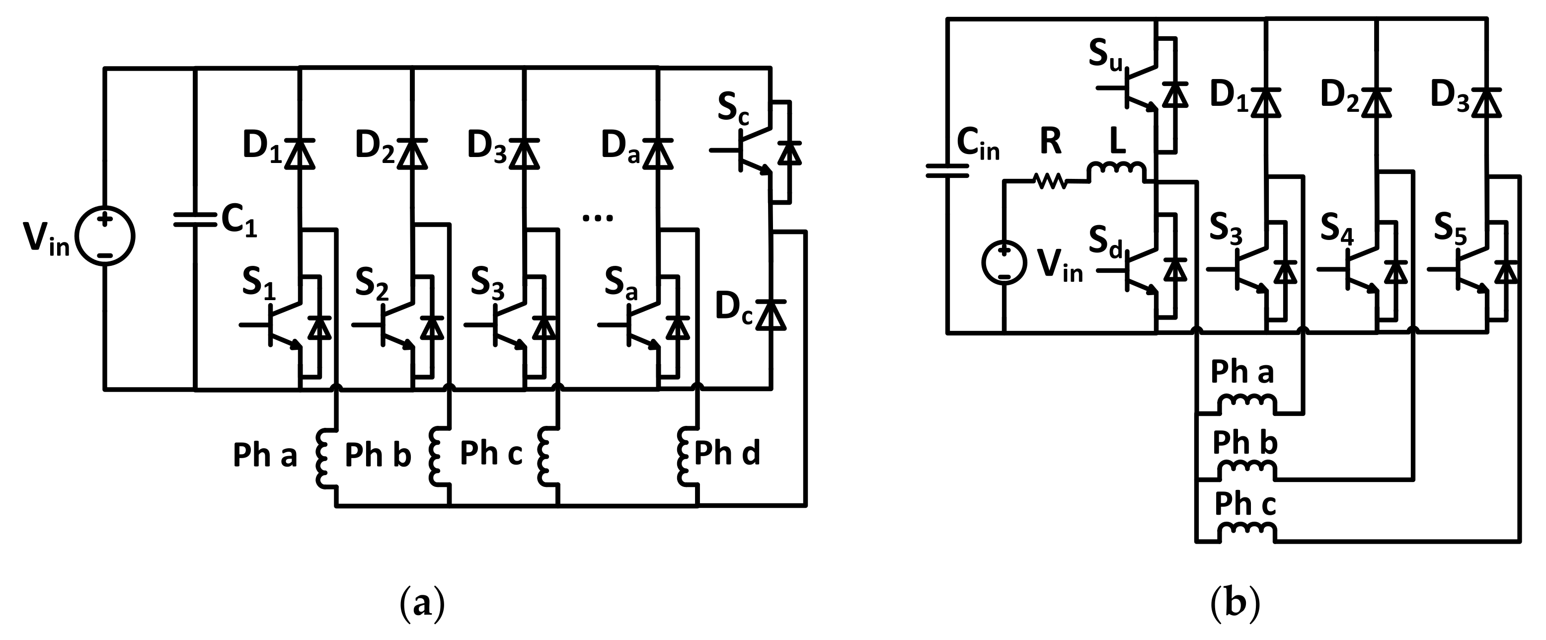
  • An integrated multi-port converter (IMPC) is presented in [10] and shown in Figure 4b. In this topology, the SRM phase voltage can be significantly increased through an integrated DC-DC boost converter to the star-connected topology. Compared to the basic star-connected configuration, IMPC needs to replace the diode of the common asymmetric leg with another switch. IMPC can offer two benefits: first, the necessary capacitance can be reduced significantly, decreasing both the cost and size of the drive; second, it can offer high torque productivity, as the magnetization and demagnetization voltages are increased. However, the boosting unit of IMPC increases the voltage stress on the capacitor and semiconductors.
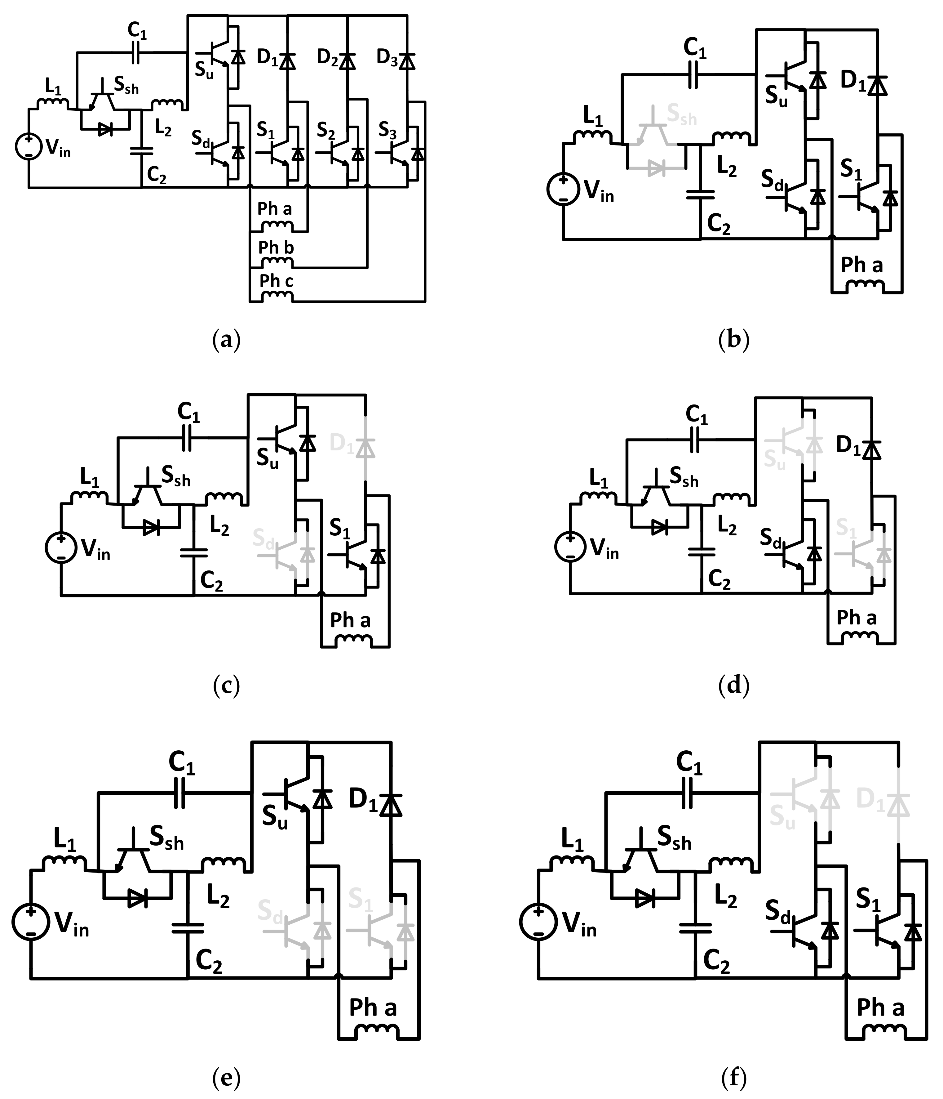
  • A quasi-Z-source integrated multiport power converter (QZIMPC), shown in Figure 5a, was recently presented in [11]. In this converter, a quasi-Z-source unit is impeded in front of IMPC in place of a single inductor. This maintains the advantages of IMPC while decreasing the voltage rating of the capacitors.
Although QZIMPC has benefits compared to the basic star-connected configuration, it cannot offer simultaneous magnetization and demagnetization to two adjacent SRM phases. This phenomenon can significantly increase the commutation period which, in turn, limits the speed range of SRM. The performance of QZIMPC was verified in [11]; the results show that high ripples of the capacitors’ voltages and input currents occur when the speed of the SRM is increased. Such ripples can cause severe thermal stress, which results in a significant reduction in the capacitors’ lifetime [19,20]. To tackle this limitation, two switching pattern algorithms for QZIMPC are presented in this paper. These control algorithms are based on prioritizing the control command in the on-going and off-going phases to fulfill the necessary load torque, as well as to accelerate the commutation time as much as possible. The algorithms introduced do not interfere with higher level controllers, such as torque sharing functions (TSF), for torque ripple minimization [12]. Following this introduction, the basic operation of QZIMPC topology is described; then, the control system, along with the proposed switching algorithms, is explained. Simulation results are then introduced to verify the feasibility of the proposed algorithms and their effects on the performance of the SRM drive system. Finally, the conclusion is presented.

2. Materials and Methods

2.1. Topology Description

The quasi-Z-source integrated multiport converter (QZIMPC) is shown in Figure 5a. It consists of a quasi-Z-source unit in front of the basic star-connected configuration. For n-phase SRM, QZIMPC uses two inductors, two small capacitors, only n + 3 switches, and n diodes. In addition, it needs n + 1 cable for wiring. By increasing the capacitors’ voltages, the necessary capacitances can be significantly decreased. The magnetization and de-magnetization times can also be decreased, and, therefore, a larger average torque could be obtained. The operation of QZIMPC consists of five modes for each phase. These modes are shown in Figure 5b–f.

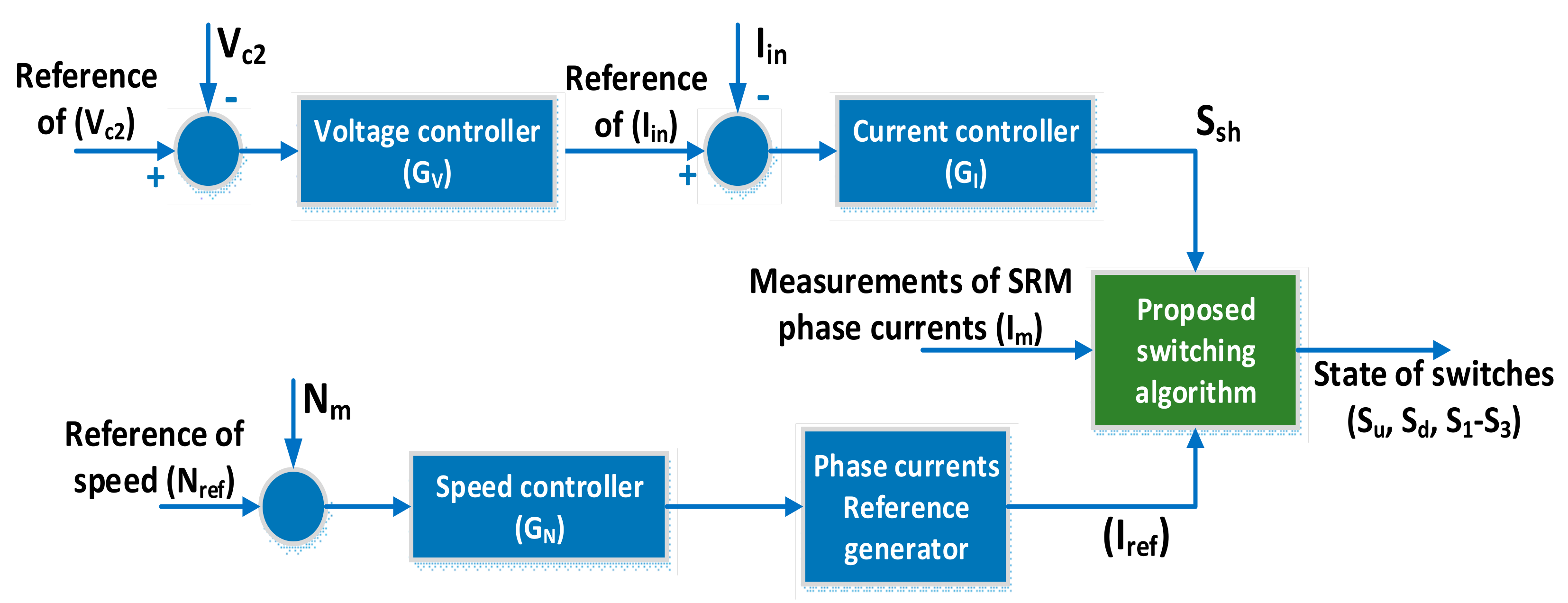
2.2. Control System Description

Figure 6 shows the control system adopted for the QZIMPC driver. It consists of two loops. The first loop regulates the capacitor voltage and input current using two controllers of GV and GI, respectively; this loop determines the duty cycles of the switch Ssh. Accordingly, it determines the shoot-through time of the quasi-Z-source unit. On the other hand, the second control loop regulates the SRM speed using controller GN. According to the load torque and the position of the SRM phases, the output of GN generates the reference values of the SRM phase currents (Iref). The PI controller, with general expression in Equation (2), is used to implement GV, GI, and GN. According to the state of Ssh (determined by the first loop), along with the reference values of the SRM phase currents (determined by the second loop), the proposed switching algorithm decides the switching states of the remaining switches (S1–S5).
G = K p + K I s

2.3. Proposed Switching Algorithm
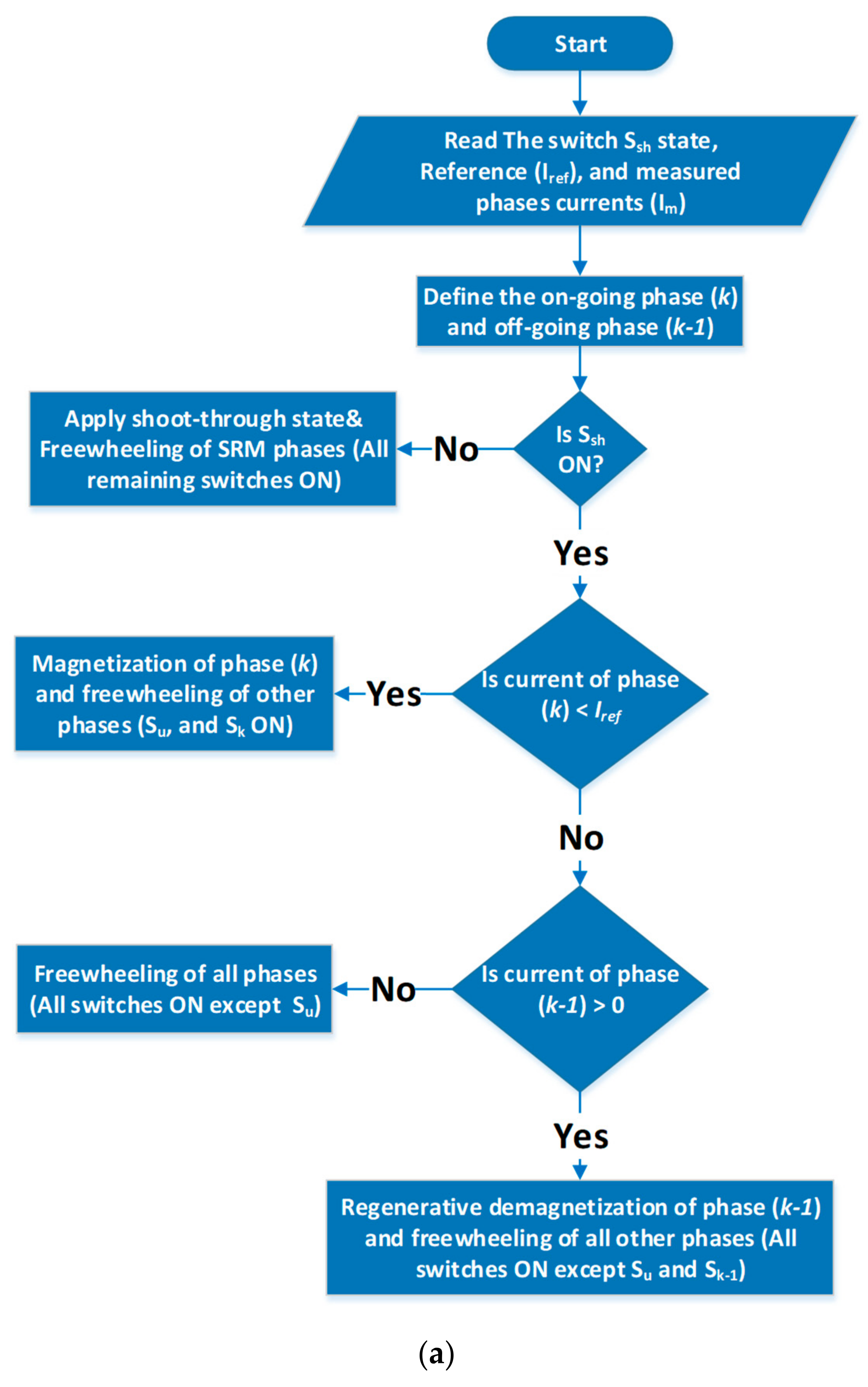
Figure 7 shows the flowchart of the proposed switching algorithms. In addition to the outputs of the two control loops (Ssh and Iref), the proposed algorithm should be fed with the measured phase currents (Im). The following steps summarize the operation of these algorithms.

2.3.1. Algorithm#1

  • The on-going and off-going phases are identified according to the reference values of SRM phase currents. They are denoted as phase k and k-1, respectively.
  • According to the state of the switch Ssh, it can be determined whether or not the quasi-Z-source unit is in the shoot-through mode. If Ssh is OFF (shoot-through mode), then the switches Su and Sd are switched ON. In addition, all other phase switches (S1–S3) are turned ON to operate the SRM phases in freewheeling mode.
  • If Ssh is ON (non-shoot through mode), the algorithm will check the measured current of the on-going phase (k).
  • If the current of that phase is less than its reference value, the switches (Su and Sk) are turned ON to apply positive voltage during that phase (magnetization mode). On the other hand, the switch Sd, along with the switches of the other phases, is turned OFF to operate these phases in freewheeling mode.
  • If the current of the on-going phase (k) is higher than or equal to its reference phase current, the algorithm will check the measured current of the off-going phase (k-1).
  • If there is no current in that phase (which means that the off-going phase is completely demagnetized), then freewheeling should be applied to on-going and off-going SRM phases. There are two options to achieve this mode: the first option is to turn the switch Sd ON along with all other phase switches (S1–S3), and the second option is to turn the switch Su ON and turn OFF all other phase switches.
  • If there is still current flowing in the off-going phase (k-1), negative voltage is applied to that phase to accelerate the demagnetization process; this is achieved through turning the switch Sd ON and turning the Sk-1 phase switch OFF; meanwhile, the remaining phases are operated in freewheeling mode by turning their corresponding switches ON.
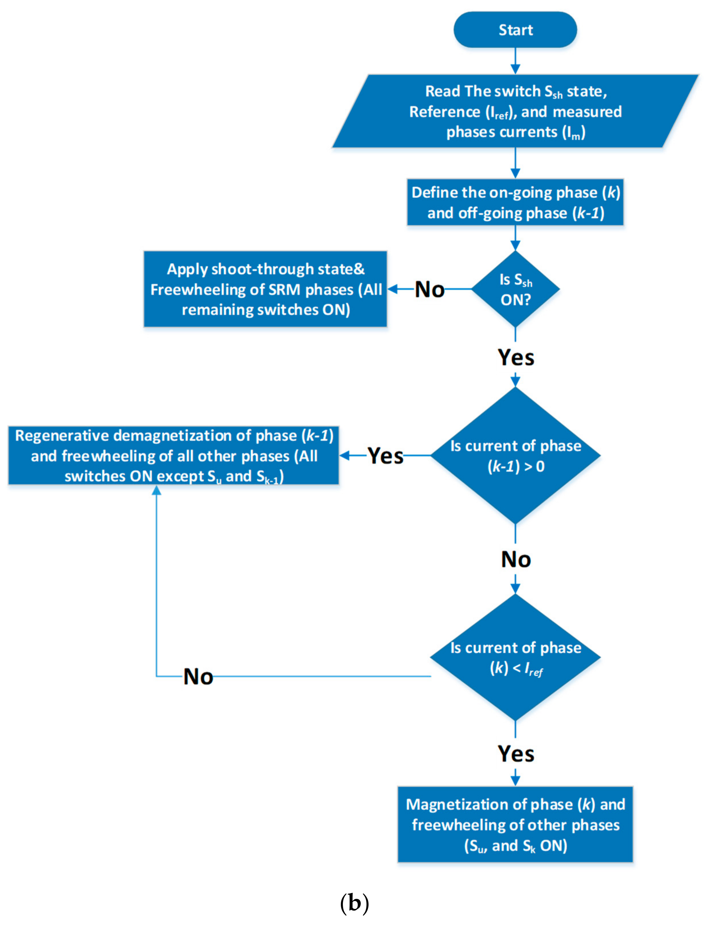
2.3.2. Algorithm#2

1–2. The first and second steps are identical to those in algorithm#1.
3. If Ssh is ON (non-shoot through mode), the algorithm will check the measured current of the off-going phase (k-1).
  • If the current of that phase is more than zero, the Sd switch is turned ON to apply negative voltage to that phase (demagnetization mode). Otherwise, the other phase switches (Si(i#k-1)) are turned ON to operate these phases in freewheeling mode.
  • If the off-going phase (k-1) is fully demagnetized, i.e., its current becomes zero, the algorithm will check the measured current of the on-going phase (k).
  • If the current of that phase is less than its reference value, the switches (Su and Sk) are turned ON to apply positive voltage during that phase (magnetization mode). On the other hand, the switch Sd, along with the other phase switches, is turned OFF to operate these phases in freewheeling mode.
  • If the current of that phase is more than or equal to its reference value, the switch Sd and all phase switches are turned ON to operate all the phases in freewheeling mode.

3. Results and Discussion

The performance of SRM with the above-introduced switching algorithms was investigated. For this purpose, the overall control system shown in Figure 6 was implemented using Matlab/Simulation. Table 1 illustrates the simulation parameters for QZIMPC and SRM. The simulation is carried out under steady-state conditions and dynamic conditions where the reference speed is stepped up. The reference value of the voltage over the capacitor C2 is 250 V. For each algorithm, the simulation is carried out at two reference speeds of 500 rpm and 1000 rpm.
For algorithm#1, Figure 8 and Figure 9 show the results at the reference speeds of 500 rpm, and 1000 rpm, respectively. Figure 10 and Figure 11 show the results for algorithm#2 at the same reference speeds. According to the simulation results, Table 2 lists the peak-to-peak values of the electrical torque (ΔTe) along with the steady-state value of the SRM phase current (Iph). The torque ripple is usually determined in terms of ΔTe as follows [21]:
T r i p p l e = T e T a v e
where Tave is the average developed electrical torque. By neglecting the mechanical losses, this average torque is equal to the load torque. Thus, at constant load torque, the value of ΔTe is usually used to imply the torque ripple [11,21].
The following points can be inferred from the simulation results:
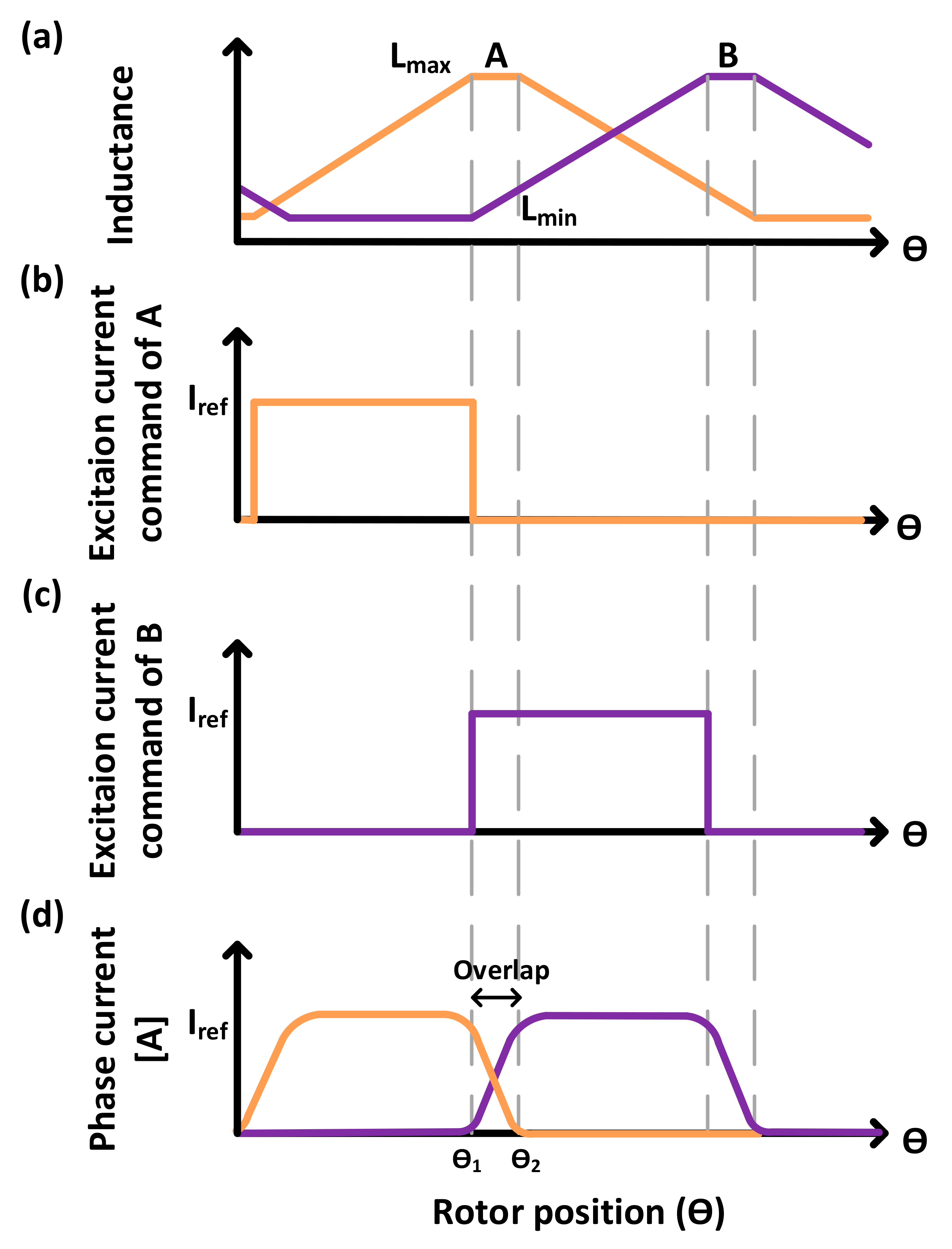
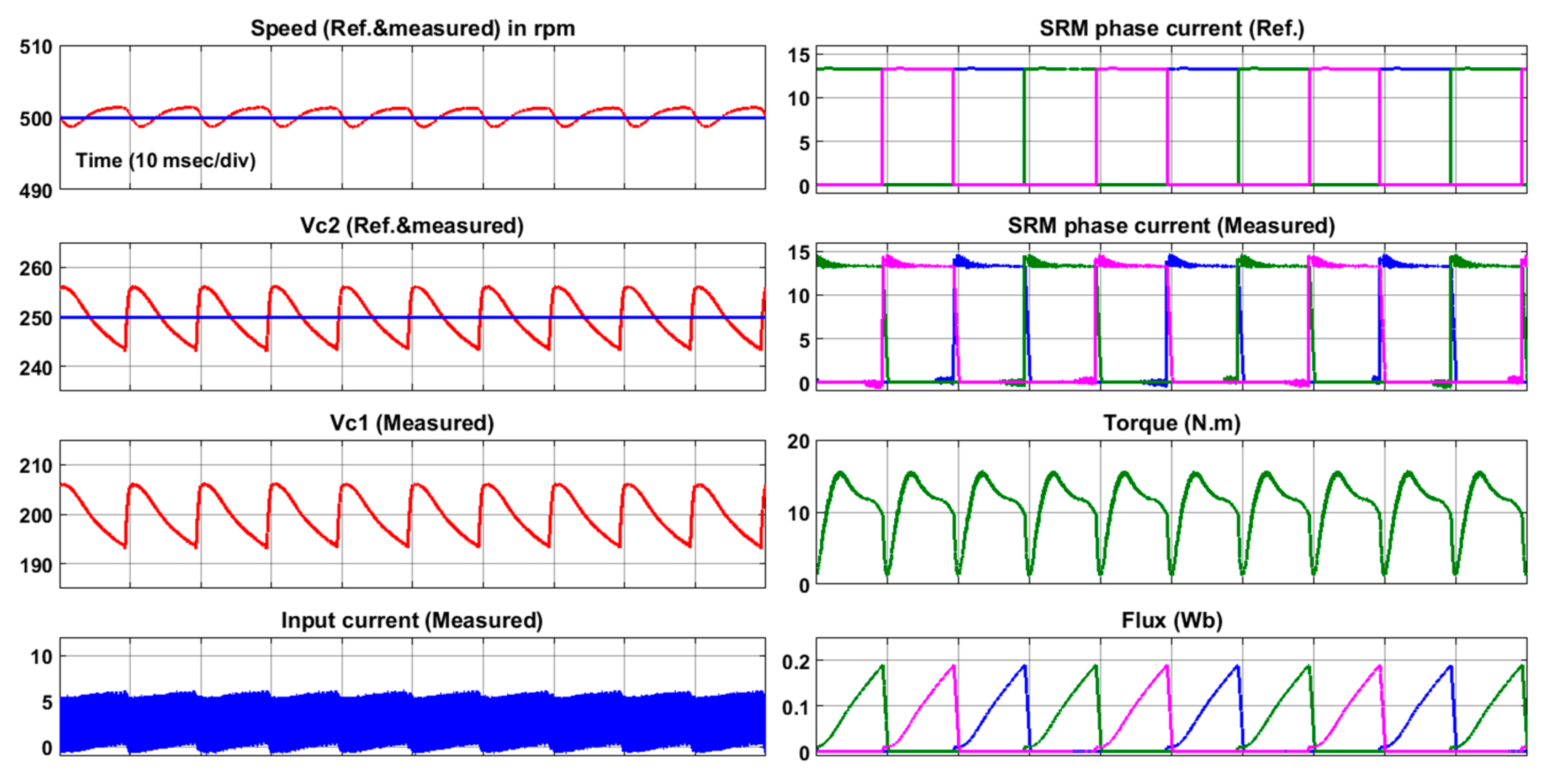
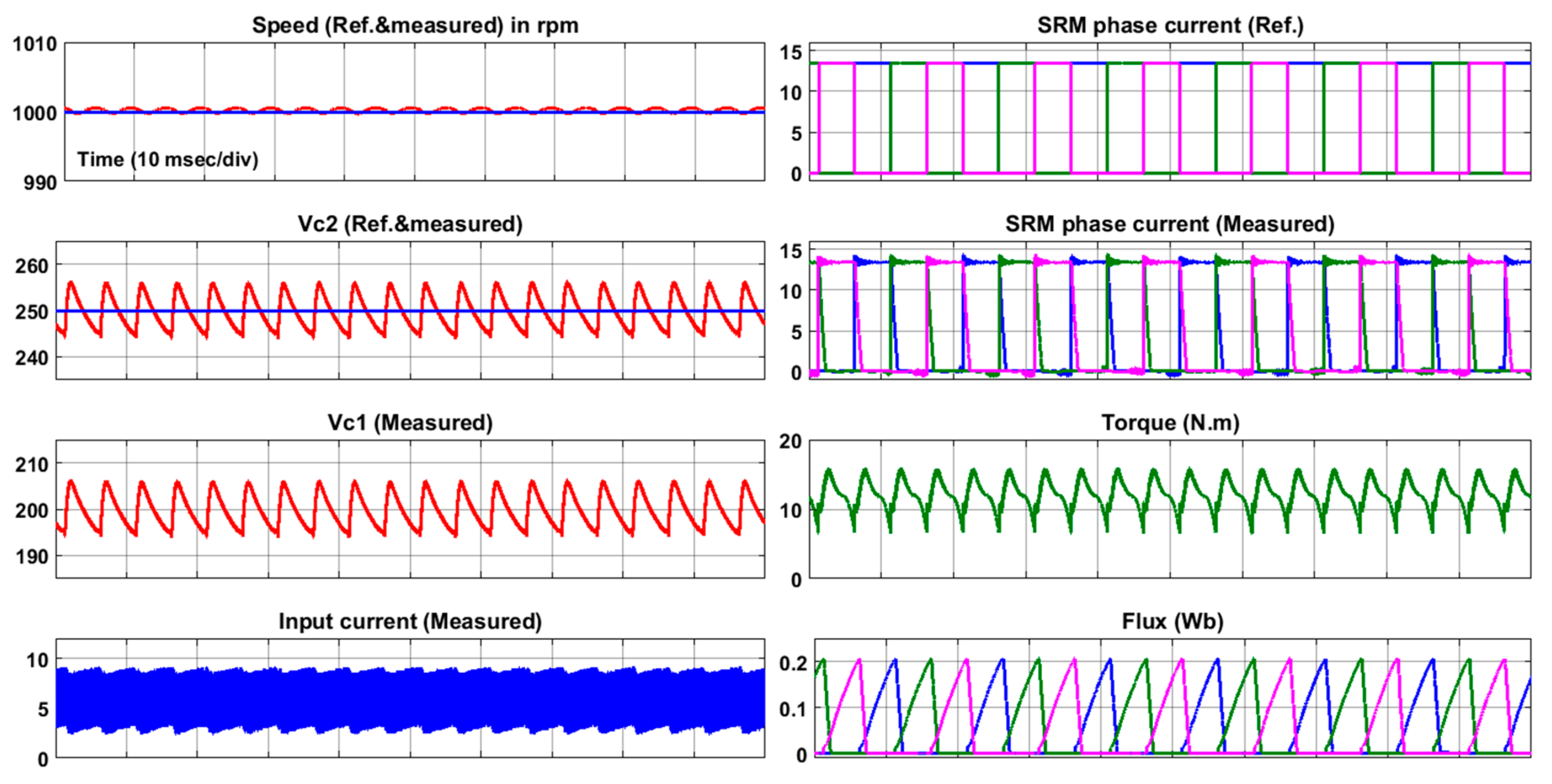
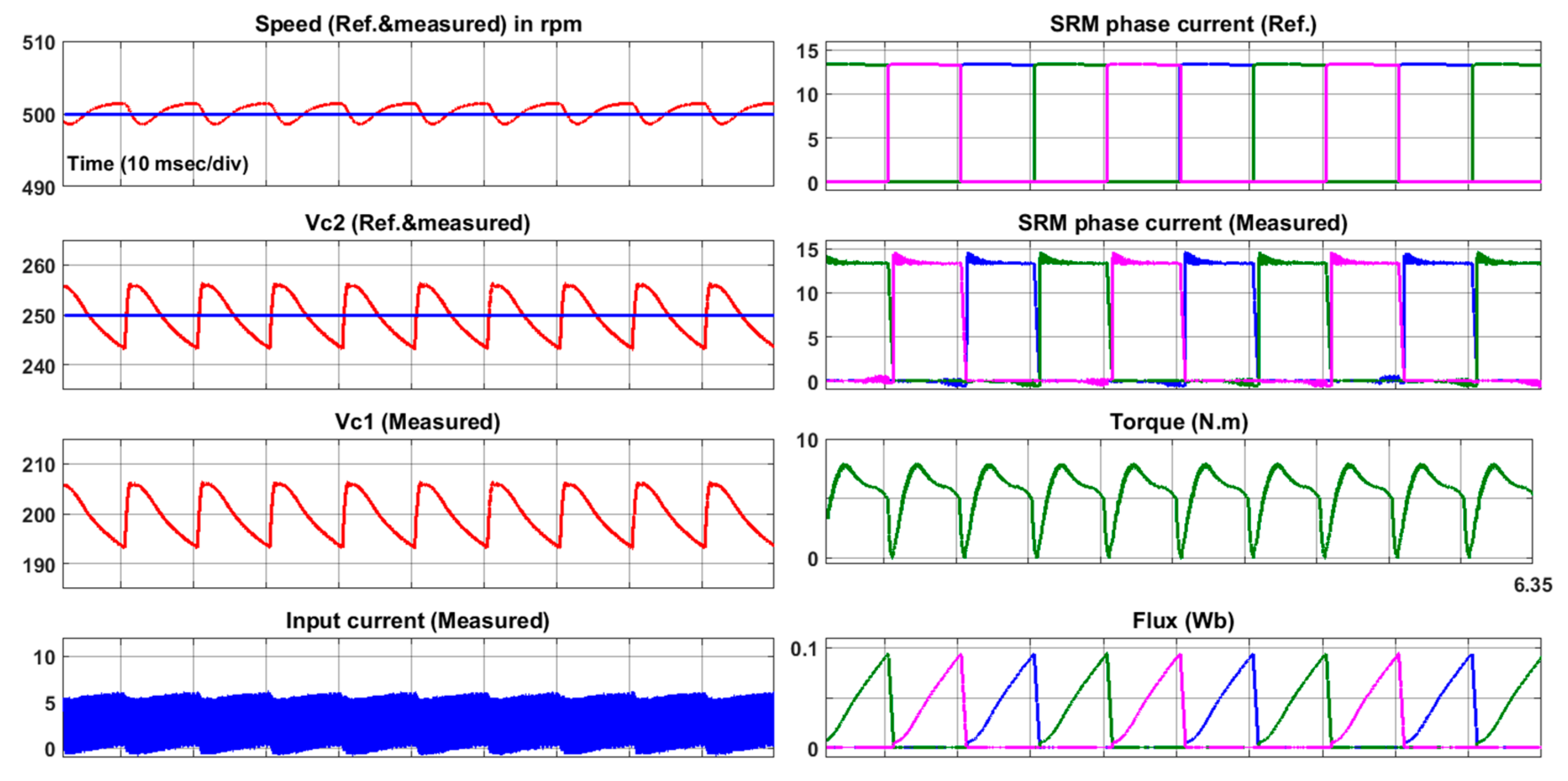
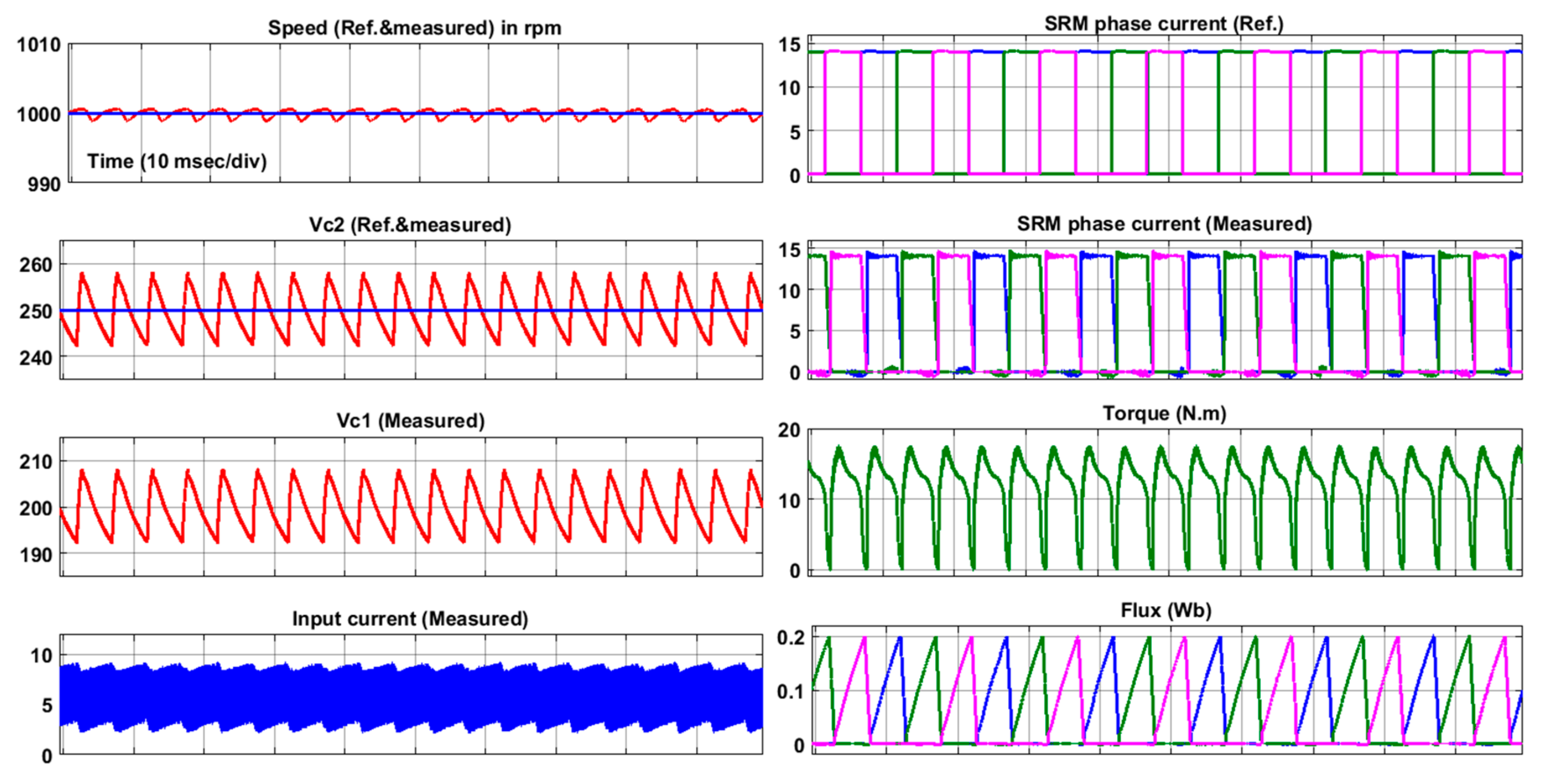
  • Table 2 shows that algorithm#1 offers low torque ripple compared to the switching algorithm#2. This can be illustrated using the torque expression in (1). According to this expression, the torque is changed with the square of the phase current. Therefore, during the demagnetization period of the off-going phase, the value of the torque produced from that phase will be decreased. To maintain constant torque, current overlap between the on-going and off-going phases should be adopted. As algorithm#1 guarantees the overlap operation of the two phases, the torque ripple can be significantly reduced. On the other hand, algorithm#2 does not allow for the magnetization of the on-going phase without ensuring complete demagnetization of the off-going phase. Therefore, the developed torque will contain higher ripple during commutation.
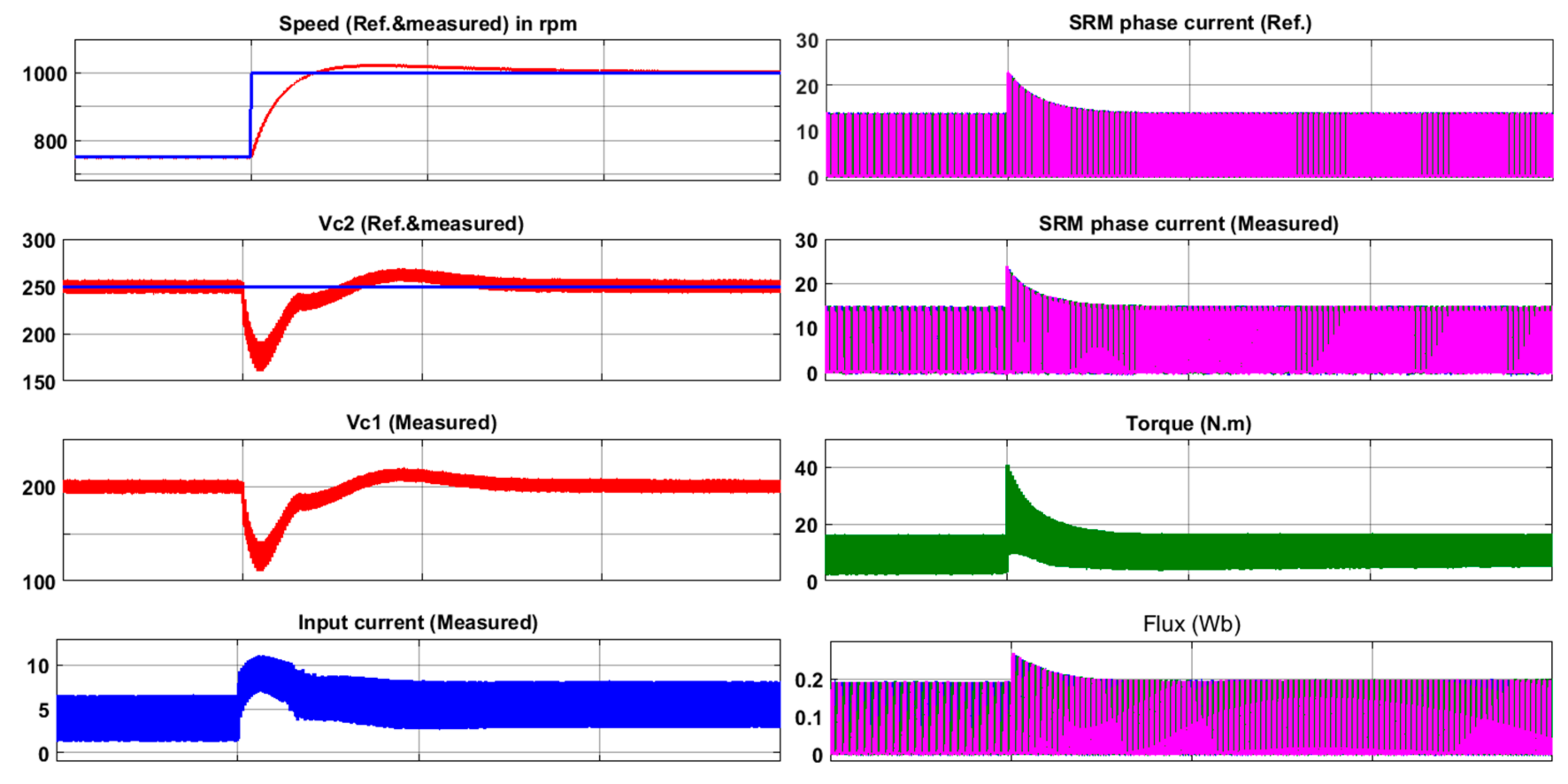
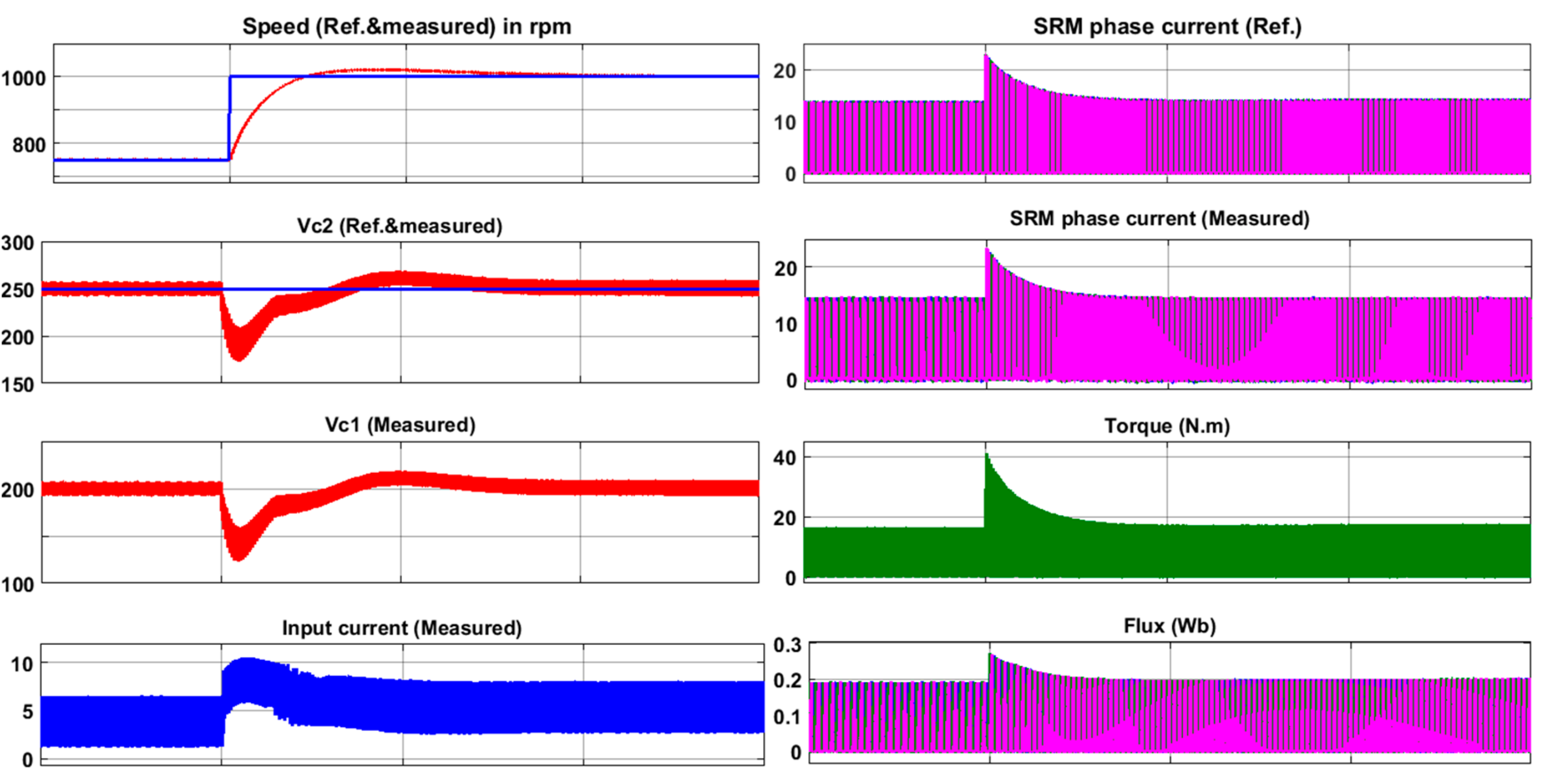
  • There is almost no significant change in the SRM phase current between the two algorithms. It is worth noting that increasing the speed of SRM does not significantly increase the SRM phase current. Increasing the speed mainly causes an increase in the input current. This implies that the motor’s increased speed is not limited by the cross-section area of the phase winding. Compared to the results revealed from [10], the switching algorithms introduced here offer wide speed range operation.
  • The capacitor voltage is well tracked. The voltage ripples over the two capacitors are also small. This guarantees the low thermal stresses expected on the capacitors of the quasi-Z-source unit. The frequency of the voltage ripples increases with motor speed.
  • According to the simulation results, more speed ripples can be observed at low speed using the two switching algorithms. Thus, adaptive controllers should be used for better performance over a wide speed range. Such adaptive controllers are usually used in systems with high inherent nonlinear characteristics, such as SRM. High performance can hardly be acquired over wide operating points by using traditional linear controllers, and these are generally not sufficient for high-performance drives. The literature has already proposed some adaptive methods to achieve this purpose with SRM, such as those in [22,23,24].
Figure 12 and Figure 13 show the related waveforms under step change in the reference speed from 750 to 1000 rpm. The motor speed is successfully changed to the new speed, and the voltage values over the capacitors are also restored after this step change. This confirms the dynamic performance of the control system with the introduced switching algorithms.
From these results, it can be concluded that the switching algorithm#1 offers a better performance than algorithm#2. This is due to the availability of overlap operations between the on-going and off-going phases during the commutation period.

4. Conclusions

This work presents two switching algorithms intended to improve the performance of SRM driven by QZIMPC. The proposed switching algorithms are based on prioritization of the control command to fulfill the required load torque for the on-going and off-going phases, as well as to accelerate the commutation process as much as possible. These algorithms do not interfere with higher level controllers, which include speed controllers, or torque ripple minimization. The feasibility of the proposed algorithms and their effect on the performance of SRM is investigated. The simulation results show that the switching algorithm#1 offers a better performance than algorithm#2. This can be explained as follows: during the demagnetization period of the off-going phase, the value of the torque produced from that phase will be decreased. This is due to the variation between the developed phase torque and the square of the phase current. Therefore, to keep the developed torque constant, current overlap between the on-going and off-going phase should be adopted. As algorithm#1 guarantees this overlap, it can offer significant a reduction in torque ripple. Algorithm#2, on the other hand, does not allow for magnetization of the on-going phase without first ensuring complete demagnetization of the off-going phase; therefore, any torque it develops will contain higher ripple during commutation.

Author Contributions

Conceptualization, M.A.G., M.O., M.D.; Methodology, M.A.G., M.O., M.D.; Software, M.A.G., A.A., M.D.; Validation, M.A.G., M.O., H.C.; Formal Analysis, A.A., M.D., M.O.; Investigation, A.A., M.A.G., M.D.; Resources, M.O. and H.C.; Data Curation, M.D., M.O.; Writing—Original Draft Preparation, M.A.G., A.A.; Writing—Review and Editing, M.D. and M.O.; Visualization, M.D., M.A.G.; Supervision, M.O.; Funding Acquisition, M.O., H.C. All authors have read and agreed to the published version of the manuscript.

Funding

This research was funded by Academy of Scientific Research and Technology (ASRT), Egypt under grant program for Egypt-China collaboration- project entitled “Basic research on switched reluctance motor drive system for electric vehicles”.

Institutional Review Board Statement

Not applicable.

Informed Consent Statement

Not applicable.

Data Availability Statement

The data can be obtained according to reasonable request to the corresponding author.

Conflicts of Interest

The authors declare no conflict of interest.

References

  1. Rojas-Delgado, B.; Alonso, M.; Amaris, H.; De Santiago, J. Wave power output smoothing through the use of a high-speed kinetic buffer. Energies 2019, 12, 2196. [Google Scholar] [CrossRef] [Green Version]
  2. Omaç, Z.; Cevahir, C. Control of switched reluctance generator in wind power system application for variable speeds. Ain Shams Eng. J. 2021, 2090447921000356. [Google Scholar] [CrossRef]
  3. Bilgin, B.; Jiang, J.W.; Emadi, A. (Eds.) Switched Rreluctance Motor Drives: Fundamentals to Applications, 1st ed.; CRC Press/Taylor & Francis Group: Boca Raton, FL, USA; Abingdon, UK, 2018. [Google Scholar]
  4. Lan, Y.; Benomar, Y.; Deepak, K.; Aksoz, A.; Baghdadi, M.; Bostanci, E.; Hegazy, O. Switched reluctance motors and drive systems for electric vehicle powertrains: State of the art analysis and future trends. Energies 2021, 14, 2079. [Google Scholar] [CrossRef]
  5. Bostanci, E.; Moallem, M.; Parsapour, A.; Fahimi, B. Opportunities and challenges of switched reluctance motor drives for electric propulsion: A comparative study. IEEE Trans. Transp. Electrif. 2017, 3, 58–75. [Google Scholar] [CrossRef]
  6. Pires, V.F.; Pires, A.J.; Cordeiro, A.; Foito, D. A review of the power converter interfaces for switched reluctance machines. Energies 2020, 13, 3490. [Google Scholar] [CrossRef]
  7. Reis, R.R.C.; Kimpara, M.L.M.; Pinto, J.O.P.; Fahimi, B. Multi-physics simulation oF 6/4 switched reluctance motor by finite element method. Eletrônica De Potecirc. 2021, 26, 1–11. [Google Scholar] [CrossRef]
  8. Neuhaus, C.R.; Fuengwarodsakul, N.H.; De Doncker, R.W. Control scheme for switched reluctance drives with minimized DC-link capacitance. IEEE Trans. Power Electron. 2008, 23, 2557–2564. [Google Scholar] [CrossRef]
  9. Liu, X.; Zhu, Z.Q.; Hasegawa, M.; Pride, A.; Deodhar, R.; Maruyama, T.; Chen, Z. Dc-link capacitance requirement and noise and vibration reduction in 6/4 switched reluctance machine with sinusoidal bipolar excitation. In Proceedings of the 2011 IEEE Energy Conversion Congress and Exposition, Phoenix, AZ, USA, 17–22 September 2011; pp. 1596–1603. [Google Scholar] [CrossRef]
  10. Cai, W.; Yi, F. An integrated multiport power converter with small capacitance requirement for switched reluctance motor drive. IEEE Trans. Power Electron. 2016, 31, 3016–3026. [Google Scholar] [CrossRef]
  11. Yi, F.; Cai, W. A Quasi-Z-source integrated multiport power converter as switched reluctance motor drives for capacitance reduction and wide-speed-range operation. IEEE Trans. Power Electron. 2016, 31, 7661–7676. [Google Scholar] [CrossRef]
  12. Husain, I. Minimization of torque ripple in SRM drives. IEEE Trans. Ind. Electron. 2002, 49, 28–39. [Google Scholar] [CrossRef]
  13. Xue, X.; Cheng, E.K.W.; Ho, S.L. Optimization and evaluation of torque-sharing functions for torque ripple minimization in switched reluctance motor drives. IEEE Trans. Power Electron. 2009, 24, 2076–2090. [Google Scholar] [CrossRef] [Green Version]
  14. Adam, A.A.; Gulez, K. Torque Control of PMSM and Associated Harmonic Ripples. Available online: https://www.intechopen.com/chapters/13716 (accessed on 10 February 2011).
  15. Pollock, C.; Michaelides, A. Switched reluctance drives: A comparative evaluation. Power Eng. J. 1995, 9, 257–266. [Google Scholar] [CrossRef]
  16. Gairola, S.; Priti; Paliwal, L.N. A new power converter for SRM drive. In Proceedings of the 2010 International Conference on Power, Control and Embedded Systems, Allahabad, India, 29 November 2010; pp. 1–6. [Google Scholar]
  17. Shamsi, P.; Fahimi, B. Single-bus star-connected switched reluctance drive. IEEE Trans. Power Electron. 2013, 28, 5578–5587. [Google Scholar] [CrossRef]
  18. Riyadi, S. Analysis of C-Dump Converter for SRM Drives. In Proceedings of the 2018 International Conference on Electrical Engineering and Informatics (ICELTICs) (44501), Banda Aceh, Indonezia, 19–20 September 2018; pp. 179–184. [Google Scholar]
  19. Yang, Y.; Ma, K.; Wang, H.; Blaabjerg, F. Instantaneous thermal modeling of the DC-link capacitor in PhotoVoltaic systems. In Proceedings of the 2015 IEEE Applied Power Electronics Conference and Exposition (APEC), Charlotte, NC, USA, 15–19 March 2015; pp. 2733–2739. [Google Scholar]
  20. Wang, H.; Blaabjerg, F. Reliability of capacitors for DC-Link applications in power electronic converters—An Overview. IEEE Trans. Ind. Appl. 2014, 50, 3569–3578. [Google Scholar] [CrossRef] [Green Version]
  21. Song, S.; Xia, Z.; Zhang, Z.; Liu, W. Control performance analysis and improvement of a modular power converter for three-phase srm with y-connected windings and neutral line. IEEE Trans. Ind. Electron. 2016, 63, 6020–6030. [Google Scholar] [CrossRef]
  22. Alrifai, M.; Zribi, M.A.; Krishnan, R.; Rayan, M. Nonlinear speed control of switched reluctance motor drives taking into account mutual inductance. J. Control. Sci. Eng. 2008, 2008, 1–11. [Google Scholar] [CrossRef] [Green Version]
  23. Reay, D.; Mirkazemi-Moud, M.; Green, T.; Williams, B. Switched reluctance motor control via fuzzy adaptive systems. IEEE Control. Syst. 1995, 15, 8–15. [Google Scholar] [CrossRef]
  24. Rouhani, H.; Milasi, R.M.; Lucas, C. Speed control of switched reluctance motor (SRM) using emotional learning based adaptive controller. In Proceedings of the 2005 International Conference on Control and Automation, Budapest, Hungary, 26–29 June 2005; Volume 1, pp. 330–334. [Google Scholar]
Figure 1. Ideal characteristics of phase inductances and phase currents with the rotor position in SRM. (a) Inductance characteristics, (b,c) Excitation current commands of phases A and B, (d) Currents in phases A and B.
Sustainability 13 09517 g001
Figure 2. Typical FEM simulation results for SRM. (a) Variation in inductance with the rotor position at different current values. (b) Torque variation with the rotor position at different current values.
Sustainability 13 09517 g002
Figure 3. Schematic of SRM−based drive system.
Sustainability 13 09517 g003
Figure 4. (a) Star-connected topology, (b) Integrated multi-port converter (IMPC).
Sustainability 13 09517 g004
Figure 5. (a) Quasi-Z-source integrated multiport power converter (QZIMPC) topology, (bf) Modes of operation for phase a (Ph a).
Sustainability 13 09517 g005
Figure 6. Control system of QZIMPC showing the proposed switching algorithm.
Sustainability 13 09517 g006
Figure 7. Flowchart of the proposed switching algorithms of QZIMPC, (a) Algorithm#1, (b) Algorithm#2.
Sustainability 13 09517 g007aSustainability 13 09517 g007b
Figure 8. Simulation results when using switching algorithm#1 at speed reference of 500 rpm.
Sustainability 13 09517 g008
Figure 9. Simulation results when using switching algorithm#1 at speed reference of 1000 rpm.
Sustainability 13 09517 g009
Figure 10. Simulation results when using switching algorithm#2 at speed reference of 500 rpm.
Sustainability 13 09517 g010
Figure 11. Simulation results when using switching algorithm#2 at speed reference of 1000 rpm.
Sustainability 13 09517 g011
Figure 12. Simulation results under step change in reference speed when using switching algorithm#1.
Sustainability 13 09517 g012
Figure 13. Simulation results under step change in reference speed when using switching algorithm#2.
Sustainability 13 09517 g013
Table 1. QZIMPC and SRM parameters for simulation.
ParameterValue
SRMSRM configuration3-phase 6/4
Inertia0.05 Kg·m2
Friction coefficient0.02 N·m·s
Inductances (L1 & L2)1 mH
QZIMPCCapacitances (C1 & C2)220 uF
Input voltage48 V
Table 2. Phase currents and torque variation with the proposed switching algorithms.
Speed ΔTeIph
500Algorithm#11–15.513
Algorithm#20–1613
1000Algorithm#18–15.513.5
Algorithm#20–1814
Publisher’s Note: MDPI stays neutral with regard to jurisdictional claims in published maps and institutional affiliations.

