Article

A Robust Control Scheme for Dynamic Voltage Restorer with Current Limiting Capability

School of Electrical and Automation Engineering, East China Jiaotong University, Nanchang 330013, China
*
Author to whom correspondence should be addressed.
Sustainability 2022, 14(24), 16752; https://doi.org/10.3390/su142416752
Submission received: 9 October 2022 / Revised: 21 November 2022 / Accepted: 24 November 2022 / Published: 14 December 2022

Abstract

:
In this paper, a second order sliding mode control scheme is utilized for outer voltage loop of a three-phase fault current limiter-based dynamic voltage restorer (FCL-DVR) instead of a conventional proportional integral/proportional resonance (PI/PR) controller. The new control strategy improves the dynamic performance of the FCL-DVR against voltage distortion. Furthermore, by using the proposed robustness controller, the FCL-DVR can smoothly switch between the FCL and DVR operation modes. Compared with other existing control schemes, the proposed control strategy for the FCL mode can still work well under a large fault current. The MATLAB/Simulink simulation results demonstrate that the proposed control strategy is robust to voltage harmonics, sag and swell. They also show that the proposed control scheme can effectively limit the fault current in different scenarios.

1. Introduction

Power quality issues such as voltage dip, voltage swell, unbalance, and harmonic pollution are the main concerns of power grids [1,2]. Nowadays, the integration of the large scale of renewable energy and other nonlinear loads further deteriorates these voltage-relevant power quality issues [3,4]. At present, a variety of voltage compensation devices have developed for the suppression of voltage-relevant power quality issues [5]. Among these devices, the dynamic voltage restorer (DVR) is favored because of its resistance to voltage dip, voltage swell, and harmonic disturbances [6]. Short circuit faults are another significant concern of power grids as they can impact the stability and safety of power grid significantly. To protect the electrical equipment from load faults, protection schemes are always implemented. Fuses, circuit breakers, bypass circuits, and fault current limiters (FCLs) are the most common types of protection schemes [7]. Fuses are cheap, small and reliable, but are disposable and require manual replacement, so are always used in low voltage systems that do not require high power supply reliability [8]. Circuit breakers, on the other hand, are the most commonly used protection devices, and can be repeatedly used and automatically reset, but have the disadvantages of larger size, higher price and the requirement of frequent maintenance [9]. Bypass circuits such as fast mechanical or solid-state switches can also be used to protect series compensation devices during a fault [10]. However, their performance against large fault currents is poor, meaning that the fault can still cause damage to electrical equipment. FCLs, compared with the above-mentioned protection devices, have the advantage of low loss, quick response and fast recovery. Therefore, FCLs have been an attractive choice for power industries [11,12].
Based on above description, it is natural to consider combining FCLs and DVRs to form a fault current limiter-based dynamic voltage restorer (FCL-DVR), which can suppress the voltage-relevant power quality issues and limit the load current at the same time. At present, there are a few FCL-DVR schemes proposed in existing publications [13,14,15]. One study [13] introduces a double functional type FCL-DVR, which can not only compensate voltage but also limit load current. This scheme limits the fault current mainly by a filter inductor, and, as a result, it is not appropriate for a large fault current. Another study [14] further proposes a bridge-type FCL-DVR, which can maintain good performance for large fault currents. Nevertheless, the power loss of the bridge-type FCL-DVR is very high, and the control scheme is relatively complex. To reduce the power loss, an energy-efficient FCL-DVR is presented in [15], but this type of scheme relies on a very complex control scheme because the shunt and series converter need to switch control schemes when the FCL-DVR changes its operating mode. In [16], a model predictive control scheme is present for the UPQC-FCL, where the system can smoothly switch between the FCL and UPQC modes. However, the number of switches of the topology is relatively high. In [17], an FCL-DVR with a reduced number of components (six switches) is present, while the total power losses cannot be neglected.
From Table 1, the proposed FCL-DVR system can compensate the voltage sag/swell and limit the fault currents simultaneously. Additionally, the power loss of the proposed system is very low when compared with the system in [13,17].
Accordingly, a smooth control scheme for an FCL-DVR is still desired. Generally, a proportional resonance (PR) controller is enough to mitigate the grid voltage harmonics in the FCL-DVR due to its good performance in tracking the sinusoidal quantity [13]. To improve the dynamic performance of DVR, J. Li, et al. have proposed an observer-based adaptive control scheme for a UPS system [18], which performs well under distorted load currents. In [16], a model predictive control scheme is presented to smooth the switching process between the FCL and UPQC modes. However, the switching frequency is not fixed in the proposed model’s predictive control. In addition, due to the advantages of the convergence in finite time, suppression of smooth disturbances of arbitrary shape and suppression of chattering, the second order sliding model control has been widely used in power electronics [19,20]. In [21], a super twisting sliding mode control is used in the DVR, where good dynamic performance and good load voltage quality are achieved under a distorted grid voltage. However, the above control schemes are not applicable when the FCL-DVR switches between the FCL and DVR modes.
Accordingly, a three-phase FCL-DVR with second-order sliding mode control scheme is designed in this paper. The proportional integral/proportional resonance (PI/PR) regulator for the outer voltage loop in series converter of the FCL-DVR is replaced by a second-order sliding mode control scheme while the PI/PR regulator for the inner current loop is kept. The control scheme of the series converter in FCL-DVR is switched in FCL or DVR modes while the control scheme of the shunt converter always remains unchanged. The new FCL-DVR control is extremely robust to external disturbances and can effectively suppress the vibration caused by the switching function. The simulation experiments confirm the effectiveness of the designed second-order sliding mode nonlinear controller.
In summary, the main contributions are listed as follows:
  • A smooth control scheme is presented for the series and shunt converter of an FCL-DVR, where the frequent switching of control schemes can be avoided.
  • A second-order sliding mode control scheme is proposed to improve the robustness of the FCL-DVR system. The stability analysis of the proposed controller is introduced.

2. Operation Principle of FCL-DVR

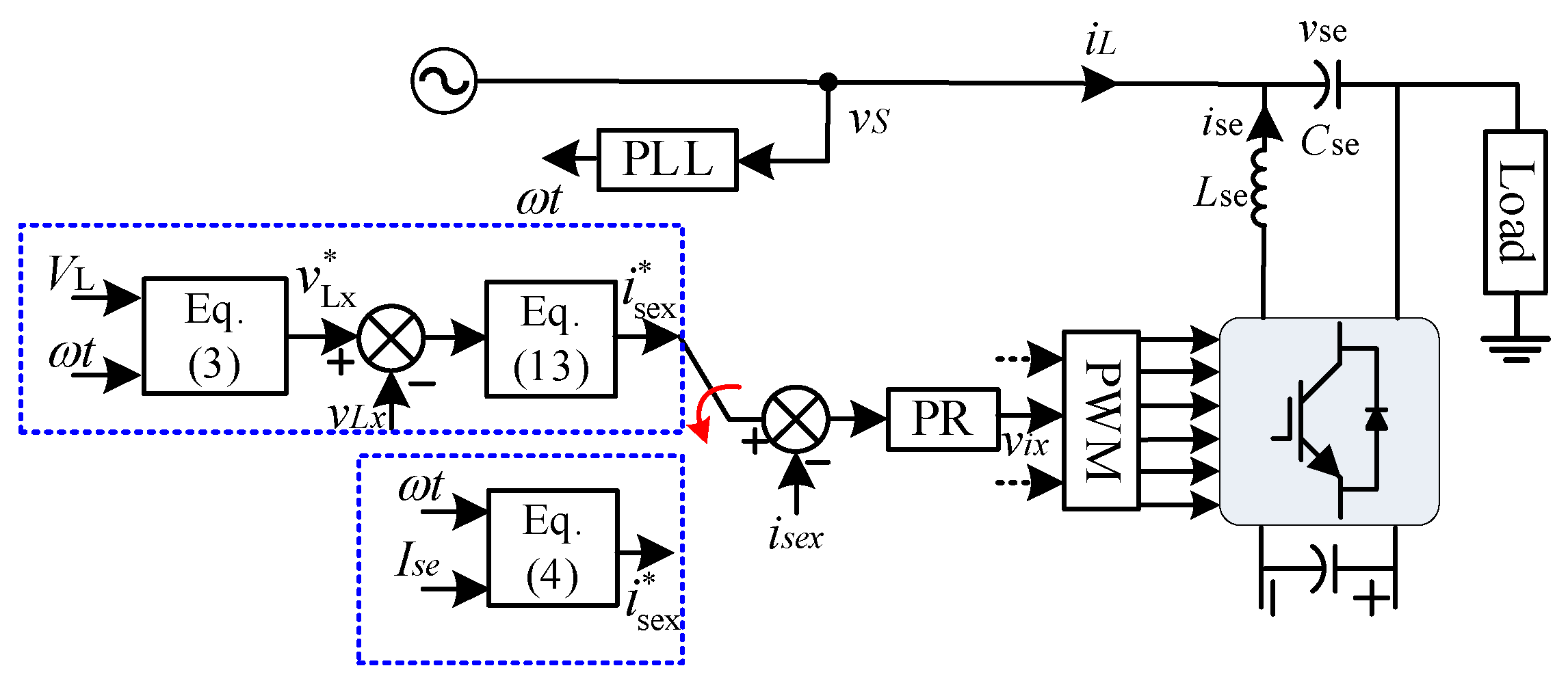
2.1. Topology of FCL-DVR

A typical FCL-DVR is shown in Figure 1. As one can see, the FCL-DVR system mainly consists of a series converter (made up of a three-phase voltage source converter), a shunt converter (made up of a three-phase voltage source converter), a line frequency transformer, filters on the AC sides of two converter and a DC-link capacitor. The series converter is connected to load through the fundamental frequency transformer, which mainly aims at compensating voltage and limiting current. The shunt converter connects to the power grid, which mainly provides the energy absorbed or released by the series converter under voltage compensation mode or current limiting mode.

2.2. FCL-DVR Operation Mode

According to the operating principle of the FCL-DVR, its operation mode can be categorized into three types.

2.2.1. Normal Operation Mode

An FCL-DVR will work in the normal operation mode when there are no power grid voltage disturbances and load faults.

2.2.2. DVR Operation Mode

The series converter will work in the DVR operation mode when there are voltage dips, voltage swells, or harmonic disturbances. It will inject voltage into the grid side to maintain the load voltage. Meanwhile, the shunt converter provides the required power for the normal operation of the series converter. Under the DVR mode, the power grid will supply the load, where the currents direction of the FCL-DVR system is seen in Figure 1a.

2.2.3. The FCL Operation Mode

The series converter on the faulted phase works in the current source mode to limit the fault current, while the series converter on the normal phases works as a voltage source to maintain the load voltage. In all likelihood, the shunt converter will still provide the required power for the normal operation of the series converter. Under the DVR mode, the power grid will supply the load, where the current direction of the FCL-DVR system is seen in Figure 1a.

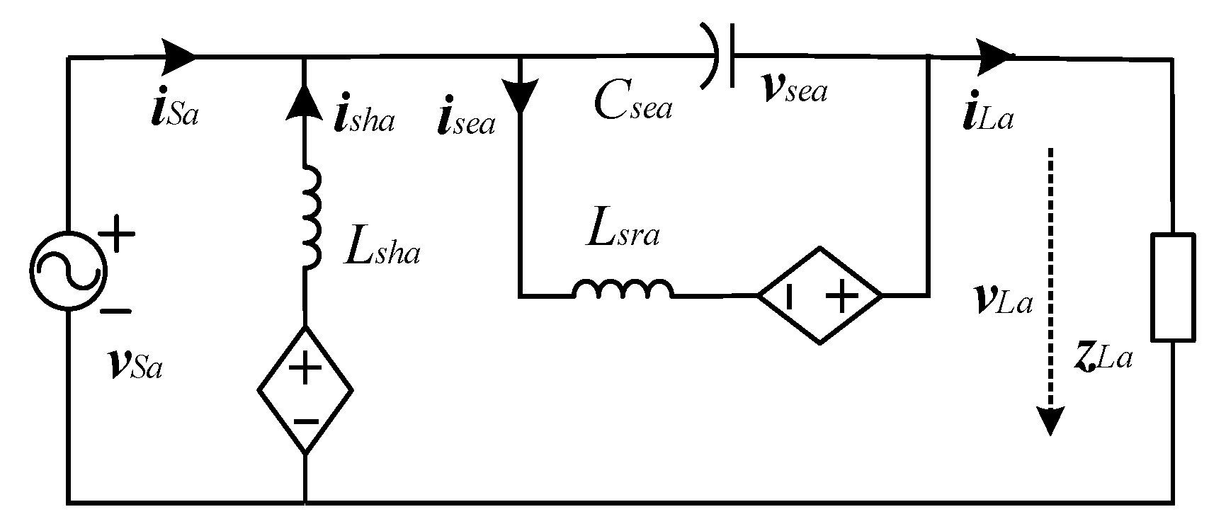
3. Mathematical Model of FCL-DVR

The equivalent circuit of the FCL-DVR is shown in Figure 2. According to Figure 2, the mathematical model of the series converter in the ABC frame can be established as follows:
C se d v se a d t = i se a i Sa C se d v se b d t = i se b i S b C se d v sec d t = i sec i Sc L se d i se a d t = R se i se a v se a + v i a L se d i se b d t = R se i se b v se b + v i b L se d i sec d t = R se i sec v sec + v i c
where v sec ( x ( { a , b , c } ) ) represents the voltage injected into the power grid; i Sx is the grid current; i sex represents series converter’s filter inductor current for the series converter. v ix represents the output voltage of the series-side converter; L se and C se represent the filter inductance and the filter capacitance of the series converter’s front-end filter; and R se is the equivalent resistance.
According to Kirchhoff’s law, the relationship between load voltage and power grid voltage can be written as:
v L a = v S a + v Se a v L b = v S b + v Se b v L c = v S c + v Se c
where v sx and v Lx represent the grid voltage and load voltage, respectively.

4. Second-Order Sliding Mode Control Scheme of FCL-DVR

The FCL-DVR is mainly used to maintain the load voltage’s frequency, magnitude, and balance in DVR mode and also to limit load fault current in FCL mode. This section introduces a second-order sliding mode control scheme to improve FCL-DVR’s dynamic features under DVR and FCL modes. The control diagram for the FCL-DVR is shown in Figure 3.
In the DVR mode, the load voltage should be controlled as:
v L a = V L sin ( ω t ) v L b = V L sin ω t 2 3 π v L c = V L sin ω t + 2 3 π
where v L represents the desired load voltage amplitude, which is equal to the rated power grid voltage. ω t represents the phase angle of the power grid voltage.
In the FCL operation mode, the inductor current is controlled as:
i se a = I se sin ( ω t ) i se b = I se sin ω t 2 3 π i se c = I se sin ω t + 2 3 π
where I se represents the desired value of the inductor current.

4.1. Design of Second-Order Sliding Mode Controller of Outer Voltage Control Loop

4.1.1. Design of the Integral Sliding Surface of the Outer Voltage Control Loop

According to (1)–(2), the dynamics of the FCL-DVR load voltage can be described as:
d v L a d t = 1 C se i se a i S a + C se d v S a d t
Define the tracking error as:
e L a = v L a v L a
where * represents the reference value of the corresponding variable.
According to (5), the integral sliding surface of the DC voltage is designed as:
s L a = e L a + λ L a e L a d t
where λ L a represents a positive sliding mode coefficient.

4.1.2. Design of the Outer Voltage Loop’s Control Law

Super-twisting algorithm (STA) [22,23,24] has the advantages of restraining vibration and quick convergence and has therefore been widely used in systems with relative order 1. In the double-closed control loop of FCL-DVR, the outer voltage loop provides reference value I se a * of inductor current for current control loop. To realize the second-order sliding mode control, the global control law I se a * mainly includes the equivalent control term and STA term. Therefore, the global control law can be defined as follows:
I se a * = I se a ( e q ) + I se a ( s t )
Equivalent control term can be obtained by solving the following equation
S ˙ L a = 0
Combine (5), (7) and (9), and the equivalent control terms can be expressed as:
I se a ( eq ) = C se v ˙ L a λ L a e L a d v S a d t + i S a
where the STA item can be designed as follows:
I se a ( st ) = C se u st
u st = ε 1 a s L a 1 2 sgn s L a + ρ L a ρ ˙ L a = ε 2 a sgn s L a
where ε 1 a and ε 2 a represent the positive constant, sgn ( ) represents the symbol function.
Substituting (11) and (12) into (8), the expression of the reference current for the inner current control loop of DVR can be expressed as:
I se a ( eq ) = C se v ˙ L a λ L a e L a d v S a d t + i S a C se ε 1 a s L a 1 2 sgn s L a C se ε 2 a sgn s L a
The control law for phase B and phase C can be obtained in the same manner.

4.1.3. Stability Analysis

Considering the internal disturbance and external disturbance, (5) can be rewritten as:
d v L a d t = d v ^ L a d t + d
where d represents the total disturbance, and ^ represents the rated values of corresponding variables. Due to the physical constraints of the practical system, it can be assumed that there is a boundary for the perturbation, that is:
| d | < ε
Substitute (14) into (7), then the first-order differential of the integral sliding mode surface s L a can be rewritten as [8]:
s ˙ L a = e ˙ L a + λ L a e L a = e ^ ˙ L a + λ e L a + d
Therefore, substitute (13) into (16), then the closed-loop system can be described as:
s ˙ L a = ε 1 a s L a 1 2 sgn s L a + ρ L a + d ρ ˙ L a = ε 2 a sgn s L a
To inspect the stability of the closed-loop system, the Lyapunov function [24] is designed as follows:
V = 2 ε 2 a s L a + 1 2 ρ L a 2 + 1 2 ε 1 a s L a 0.5 sgn s L a ρ L a 2 = ξ a T P a ξ a
where
ξ a = | s L a | 1 2 sgn ( s L a ) ρ L a
P a = 1 2 4 ε 2 a + ε 1 a 2 ε 1 a ε 1 a 2
then, the differential of Lyapunov function V can be calculated as (19)
V ˙ = 1 s L a 1 2 ξ a T Q a ξ a + d s L a 1 2 q a T ξ a
where
Q a = ε 1 a 2 2 ε 2 a + ε 1 a 2 ε 1 a ε 1 a 1
q a = ε 1 a 2 2 ε 2 a + 0.5 ε 1 a 2 0.5 ε 1 a
In practice, there is a boundary for the perturbation | d | < ε , and, according to [24], (19) can be further written as:
V ˙ 1 s L a 1 2 ξ a T Λ a ξ a
where
Λ a = ε 1 a 2 2 ε 2 a + ε 1 a 2 4 ε 2 a ε 1 a ε ε 1 a + 2 ε ε 1 a + 2 ε 1
To ensure the stability of the designed controller, a matrix Λ a should be designed as a positive semidefinite matrix to ensure V ˙ 0 . Therefore, the following conditions should be satisfied:
ε 1 d > 2 ε ε 2 d > ε 1 d 5 ε 1 d ε + 4 ε 2 2 ε 1 d 2 ε

4.1.4. Parameters of the Sliding Mode Control

The second-order sliding mode controller for the outer voltage loop in FCL-DVR mainly includes three sliding mode coefficients: λ L a , ε 1 a and ε 2 a . As can be seen from Formula (6), the coefficient λ L a has a direct impact on the dynamic response of the closed-loop system. A large λ L a leads to a fast dynamic response, but will easily cause an overshoot; A small λ L a will slow the dynamic response of the system. Therefore, the coefficient λ L a must be selected reasonably. The principle of the selection of λ L a has been introduced in [18]. Additionally, in order to ensure the stability of the designed controller, ε 1 a and ε 2 a can be determined by (21).

4.2. Design of Inner Current Loop’s PR Controller

The main objectives of the inner current loop include: (1) the stable tracking of the output of the load voltage in the DVR mode, to achieve the goal of maintaining the load voltage stability; (2) In FCL mode, the desired inductor current’s reference value is tracked to limit the load fault current. In order to track inductive current reference, the current inner ring uses a PR controller, which can be written as:
G P R ( s ) = k p + k r s s 2 + h w 2
where k p and k r represent the controller gain. The PR regulator is able to adjust the current error in a steady-state mode at zero, in the h-order harmonic frequency. Integration is performed using the proportional gain k p and resonant gain k i , where the resonant component is a quadratic resonance filter with resonant frequency equal to h w with zero damping coefficient and can be used to determine the selectivity of the filter. In practice, the bandwidth can be expanded to reduce sensitivity to frequency changes in the grid. In addition, the detailed parameters design is shown in [25].

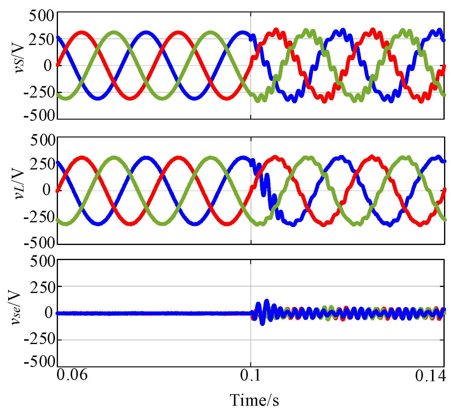
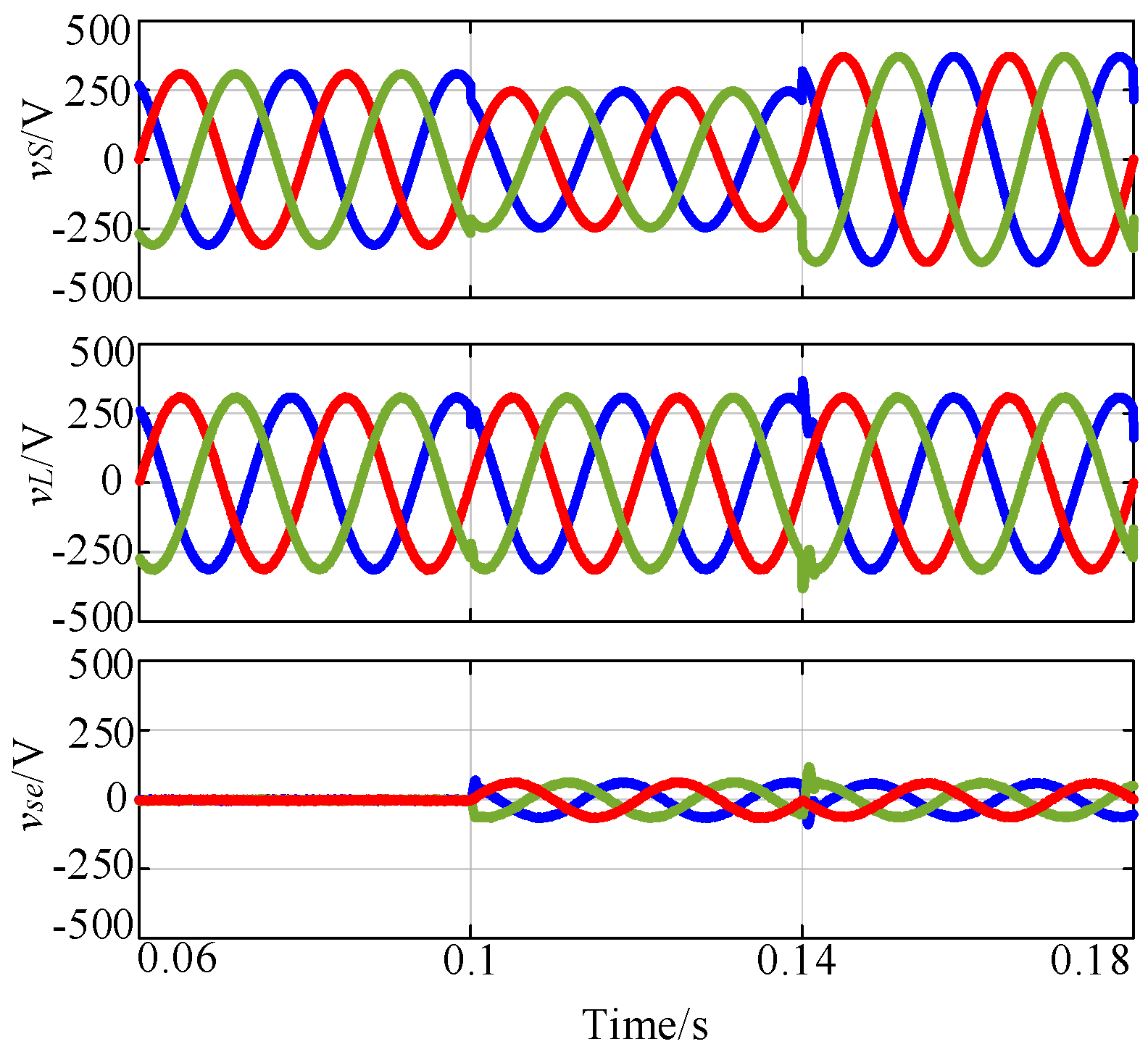
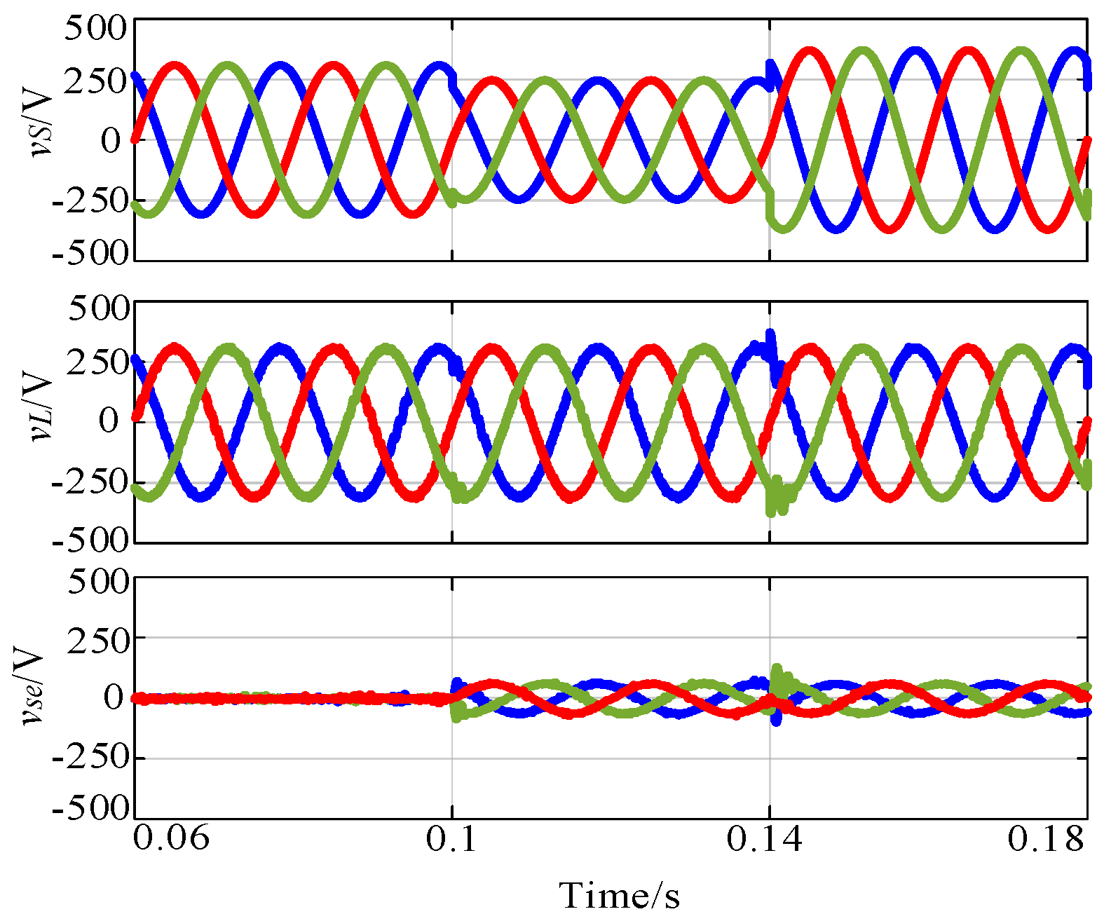
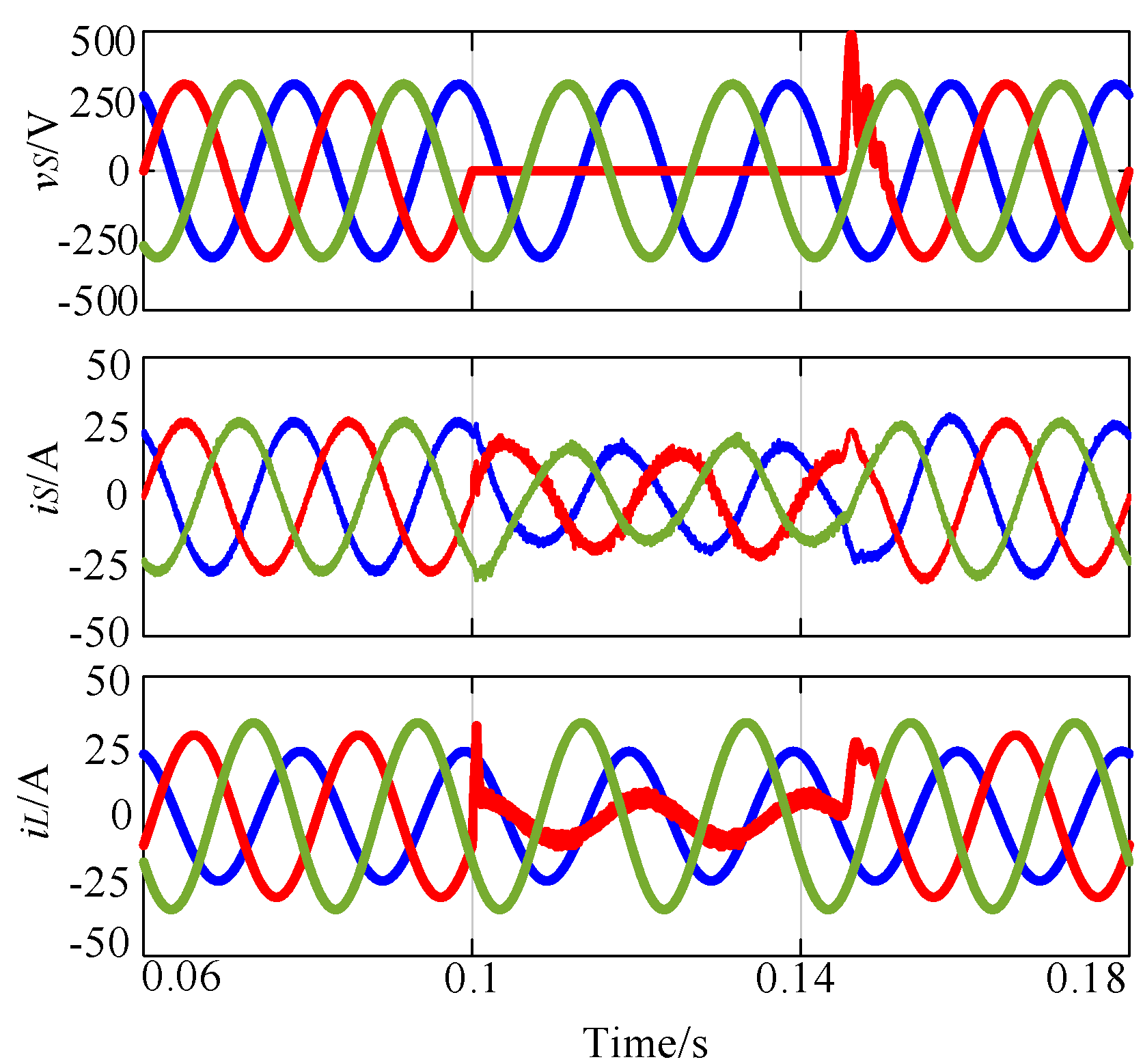
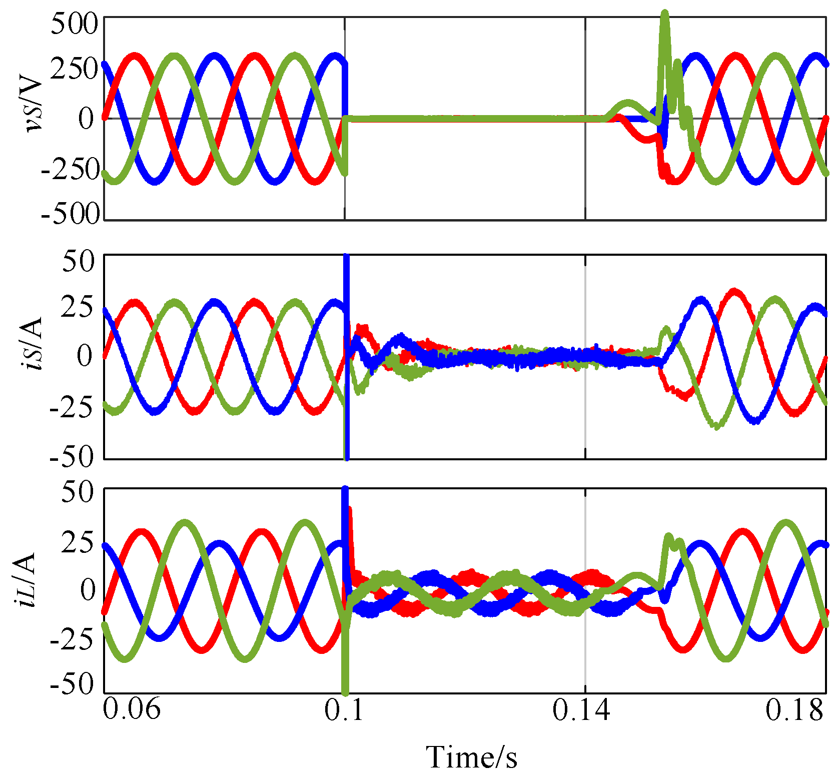
5. Simulation Results

MATLAB/Simulink simulations are conducted in this section to verify the correctness and effectiveness of the proposed second-order sliding mode control scheme. The parameters of the FCL-DVR and its control setting are listed in Table 2 and Table 3, respectively. As a comparison, the simulation results for an FCL-DVR with conventional PR regulator are also presented.
Figure 4 and Figure 5 show the simulation results of the FCL-DVR with the proposed second-order sliding mode controller under the distorted grid voltage, and they include the grid voltage v s , load voltage v L , and series injected voltage v s e . As seen in Figure 4, when the grid voltage is distorted, the DVR injects a compensation voltage into the power grid through the series converter. With the compensation of the series converter, the grid voltage contains small harmonics so that it remains a sinusoidal signal. Figure 5 presents the simulation results of the three-phase FCL-DVR with conventional PR regulator under distorted voltage. The results in Figure 5 indicate the conventional PR control scheme cannot guarantee a sinusoidal load voltage when the grid voltage is distorted within [0.1, 0.14] s. Hence, the results verify that the proposed second-order sliding mode controller is superior to the conventional PI/PR controller in terms of restraining the harmonic distortion.
Figure 6 and Figure 7 show the simulation results of three-phase FCL-DVRs with second-order sliding mode controller and PR controller in a grid with a voltage dip and voltage swell. As seen from these two figures, both control schemes result in sinusoidal, balanced, and constant-magnitude voltages after short transients. Nevertheless, the proposed second-order sliding mode controller reduces the transient time and the overshooting compared with the conventional PR control at 0.1 and 0.14s. Therefore, the proposed second-order sliding mode controller has a better dynamic feature.
Figure 8 illustrates the simulation results of the FCL-DVR under a phase-A fault. One can see from the figure that the three-phase FCL-DVR switches from the DVR mode to the current limiter mode at 0.1 s after the phase-A fault occurs. In such a condition, the phase-A load voltage reduces to almost 0 because phase A is shorted. As a result, the load current is contained to the desired values. When the fault disappears, the three-phase FCL-DVR will switch back to DVR mode, and the load voltage and current return to normal.
Figure 9 gives the simulation of a three-phase FCL-DVR under three-phase grounding fault. The figure indicates that the three-phase FCL-DVR will switch from the DVR mode to current limiter mode at 0.1 s after the three-phase grounding fault is detected. For such a case, the load voltage for three phases reduces to almost 0, and, as a result, grid current declines to almost 0, and the load current is maintained at desired values. After the fault disappears, the three-phase FCL-DVR will switch back to DVR mode, and the load voltage and current will return to normal values.

6. Conclusions

To effectively improve the robustness of the three-phase FCL-DVR load voltage controller, this paper proposes a new second-order sliding mode controller. Compared with three-phase DVR in which the series converter applies PI/PR for the outer voltage loop and inner current loop, the new control scheme has a better resistance to grid voltage disturbance. The main conclusions for this paper are:
(1)
A second-order sliding mode controller can result in a better resistance to voltage disturbance than the conventional PI/PR regulator.
(2)
A second-order sliding mode controller can have a better dynamic feature than the conventional PI/PR regulator as the second-order sliding mode controller reduces the response time and overshooting.
(3)
The FCL-DVR with a second-order sliding controller can maintain the large fault current by switching the control mode from DVR to FCL.
MATLAB/Simulink simulation results verify the good robustness and superior fault flow limiting capability of the proposed scheme.

Author Contributions

Conceptualization, X.X.; Methodology, J.S.; Writing—original draft, J.S.; Writing—review & editing, X.X.; Visualization, J.S.; Supervision, X.X. All authors have read and agreed to the published version of the manuscript.

Funding

This research received no external funding.

Institutional Review Board Statement

Not applicable.

Informed Consent Statement

Not applicable.

Data Availability Statement

Not applicable.

Conflicts of Interest

The authors declare no conflict of interest.

References

  1. Shen, Z.; Xu, B.; Liu, C.; Hu, C.; Liu, B.; Xu, Z.; Jin, L.; Chen, W. The Modeling and Simplification of a Thermal Model of a Planar Transformer Based on Internal Power Loss. Sustainability 2022, 14, 11915. [Google Scholar] [CrossRef]
  2. Liang, X. Emerging Power Quality Challenges Due to Integration of Renewable Energy Sources. IEEE Trans. Ind. Appl. 2017, 53, 855–866. [Google Scholar] [CrossRef]
  3. Mahela, O.P.; Shaik, A.G.; Gupta, N. A critical review of detection and classification of power quality events. Renew. Sustain. Energy Rev. 2015, 41, 495–505. [Google Scholar] [CrossRef]
  4. Xu, Q.; Zhang, C.; Wen, C.; Wang, P. A novel composite nonlinear controller for stabilization of constant power load in DC microgrid. IEEE Trans. Smart Grid 2017, 10, 752–761. [Google Scholar] [CrossRef]
  5. Peñalvo-López, E.; León-Martínez, V.; Montañana-Romeu, J.; Cárcel-Carrasco, J. Passive Reactive Power Compensators for Improving the Sustainability of Three-Phase, Four-Wire Sinusoidal Systems Supplied by Unbalanced Voltages. Sustainability 2021, 13, 11134. [Google Scholar] [CrossRef]
  6. Chen, X.; Xie, Q.; Bian, X.; Shen, B. Energy-saving superconducting magnetic energy storage (SMES) based interline DC dynamic voltage restorer. CSEE J. Power Energy Syst. 2021, 8, 238–248. [Google Scholar]
  7. Najy, W.K.A.; Zeineldin, H.H.; Woon, W.L. Optimal protection coordination for microgrids with grid-connected and islanded capability. IEEE Trans. Ind. Electron. 2012, 60, 1668–1677. [Google Scholar] [CrossRef]
  8. Std C37.48-2020; IEEE Guide and Tutorial for the Application of High-Voltage (>1000 V) Fuses and Accessories. (Revision of IEEE Std C37.48-2005 and IEEE Std C37.48.1-2011). IEEE: Piscataway, NJ, USA, 2020. [CrossRef]
  9. Sneath, J.; Rajapakse, A.D. Fault detection and interruption in an earthed HVDC grid using ROCOV and hybrid DC breakers. IEEE Trans. Power Deliv. 2014, 31, 973–981. [Google Scholar] [CrossRef]
  10. Huber, J.E.; Kolar, J.W. Applicability of solid-state transformers in today’s and future distribution grids. IEEE Trans. Smart Grid 2017, 10, 317–326. [Google Scholar] [CrossRef]
  11. Sharaf, H.M.; Zeineldin, H.H.; El-Saadany, E. Protection Coordination for Microgrids With Grid-Connected and Islanded Capabilities Using Communication Assisted Dual Setting Directional Overcurrent Relays. IEEE Trans. Smart Grid 2018, 9, 143–151. [Google Scholar] [CrossRef]
  12. Abramovitz, A.; Ma Smedley, K. Survey of Solid-State Fault Current Limiters. IEEE Trans. Power Electron. 2012, 27, 2770–2782. [Google Scholar] [CrossRef]
  13. Zhikang, S.; Peng, Y.; Shen, Z.J.; Tu, C.; Jiang, F.; Cheng, Y. Design considerations of a fault current limiting dynamic voltage restorer (FCLDVR). IEEE Trans. Smart Grid 2015, 6, 14–25. [Google Scholar]
  14. Jiang, F.; Tu, C.; Shuai, Z.; Cheng, M.; Lan, Z.; Xiao, F. Multilevel cascaded-type dynamic voltage restorer with fault current limiting function. IEEE Trans. Power Deliv. 2016, 31, 1261–1269. [Google Scholar] [CrossRef]
  15. Nourmohamadi, H.; Sabahi, M.; Balsara, P.T.; Babaei, E.; Hosseini, S.H.; Fakhim-Babaei, A. New Concept for Fault Current Limiter with Voltage Restoration Capability. IEEE Trans. Ind. Electron. 2020, 67, 10001–10010. [Google Scholar] [CrossRef]
  16. Han, J.; Li, X.; Sun, Y.; Gong, S.; Huang, S. Quadruple-active-bridge based unified power quality conditioner-L with fault current limiting capability. Electr. Power Syst. Res. 2022, 206, 107780. [Google Scholar] [CrossRef]
  17. Ghavidel, P.; Farhadi, M.; Dabbaghjamanesh, M.; Jolfaei, A.; Sabahi, M. “Fault Current Limiter Dynamic Voltage Restorer (FCL-DVR) With Reduced Number of Components”. IEEE J. Emerg. Sel. Top. Ind. Electron. 2021, 2, 526–534. [Google Scholar] [CrossRef]
  18. Li, J.; Sun, Y.; Li, X.; Xie, S.; Lin, J.; Su, M. Observer-Based Adaptive Control for Single-Phase UPS Inverter Under Nonlinear Load. IEEE Trans. Transp. Electrif. 2022, 8, 2785–2796. [Google Scholar] [CrossRef]
  19. Cavallo, A.; Russo, A.; Canciello, G. Control of Supercapacitors for smooth EMA Operations in Aeronautical Applications. In Proceedings of the 2019 American Control Conference (ACC), Philadelphia, PA, USA, 10–12 July 2019; pp. 4948–4954. [Google Scholar] [CrossRef]
  20. Russo, A.; Canciello, G.; Cavallo, A. Generalized Super-Twisting control of a Dual Active Bridge for More Electric Aircraft. In Proceedings of the 2021 European Control Conference (ECC), Delft, The Netherlands, 29 June–2 July 2021; pp. 1610–1615. [Google Scholar] [CrossRef]
  21. Biricik, S.; Komurcugil, H.; Ahmed, H.; Babaei, E. Super Twisting Sliding-Mode Control of DVR With Frequency-Adaptive Brockett Oscillator. IEEE Trans. Ind. Electron. 2021, 68, 10730–10739. [Google Scholar] [CrossRef]
  22. Benbouhenni, H.; Bizon, N.; Colak, I.; Thounthong, P.; Takorabet, N. Simplified Super Twisting Sliding Mode Approaches of the Double-Powered Induction Generator-Based Multi-Rotor Wind Turbine System. Sustainability 2022, 14, 95014. [Google Scholar] [CrossRef]
  23. Sun, D.; Wang, X.; Nian, H.; Zhu, Z.Q. A Sliding-Mode Direct Power Control Strategy for DFIG Under Both Balanced and Unbalanced Grid Conditions Using Extended Active Power. IEEE Trans. Ind. Electron. 2018, 33, 1313–1322. [Google Scholar] [CrossRef]
  24. Hu, J.; Nian, H.; Hu, B.; He, Y.; Zhu, Z.Q. Direct Active and Reactive Power Regulation of DFIG Using Sliding-Mode Control Approach. IEEE Trans. Energy Convers. 2010, 25, 1028–1039. [Google Scholar] [CrossRef]
  25. Hung, V.T.; Shu, H.; Giang, L.N.; The, N.D. Double-loop control structure using proportional resonant and sequence-decoupled resonant controllers in static coordinates for dynamic voltage restorer. Chin. J. Electr. Eng. 2019, 5, 10–19. [Google Scholar] [CrossRef]
Figure 1. Topology of the three-phase FCL-DVR.
Sustainability 14 16752 g001
Figure 2. FCL-DVR system A phase equivalent circuit.
Sustainability 14 16752 g002
Figure 3. Control block diagram of FCL-DVR.
Sustainability 14 16752 g003
Figure 4. Simulation waveform of FCL-DVR under the second-order sliding mode control scheme under distorted grid voltage.
Sustainability 14 16752 g004
Figure 5. Simulation waveform of FCL-DVR under the PR scheme under distorted grid voltage.
Sustainability 14 16752 g005
Figure 6. FCL-DVR simulation waveform under the second-order sliding mode control scheme during the power grid voltage sag and temporary swell.
Sustainability 14 16752 g006
Figure 7. Simulation waveform of FCL-DVR under PR scheme during temporary voltage sag and temporary swell.
Sustainability 14 16752 g007
Figure 8. A Simulation waveform of FCL-DVR during phase ground failure.
Sustainability 14 16752 g008
Figure 9. Simulation waveform of the FCL-DVR during a three-phase ground failure.
Sustainability 14 16752 g009
Table 1. Comparison results with other FCL systems.
ReferenceNumber of Line TransformersNumber of Switches in 3 PhasePower LossesCompensation Voltage SagLimiting Fault Current Ability
[13]224Highyesyes
[16]034N/AyesYes
[17]16Mediumyesyes
Proposed system112N/Ayesyes
Table 2. The FCL-DVR parameters used for the simulation.
ParametersValues
Grid voltage380 V
Grid angular frequency314 rad/s
Series converter’s filter capacitance80 µF
Series converter’s filter inductance6 mH
DC capacitance4000 µF
DC voltage800 V
Grid equivalent resistance0.5 Mh
Load resistance10 kHz
Table 3. Control parameters used for the simulation.
Control ParametersValues
Second-order sliding mode controller
λ L a 46
ε 1 a 6173
ε 2 a 2.162 × 10⁶
PR controller
k p 2
k r 800
Publisher’s Note: MDPI stays neutral with regard to jurisdictional claims in published maps and institutional affiliations.

