1. Introduction
Concepts such as green mining and ecological mining have been put forward one after another recently. They aim toward a coal-resource mining model with optimal socio-economic benefits and minimal ecological environmental impact; the environmental disturbance caused by mines should be less than the environmental capacity. The model has been widely recognized by the international mining community [
1,
2,
3]. The recoverable resources in the central and eastern regions are increasingly exhausted by long-term high-intensity coal mining. Resources are being exploited under buildings, railways, and water bodies in western China with a burial depth greater than 1000 m for energy succession as soon as possible [
4,
5].
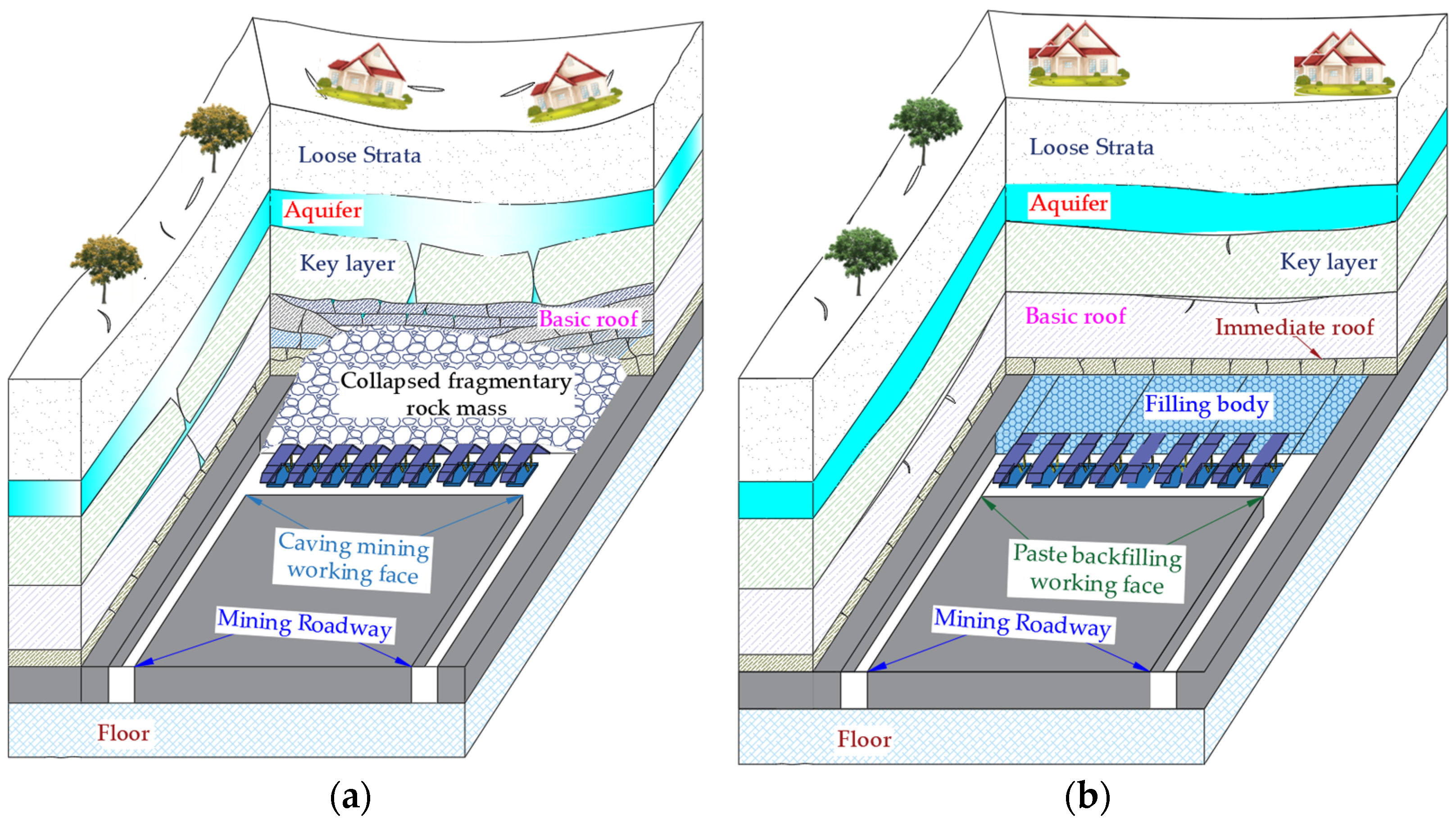
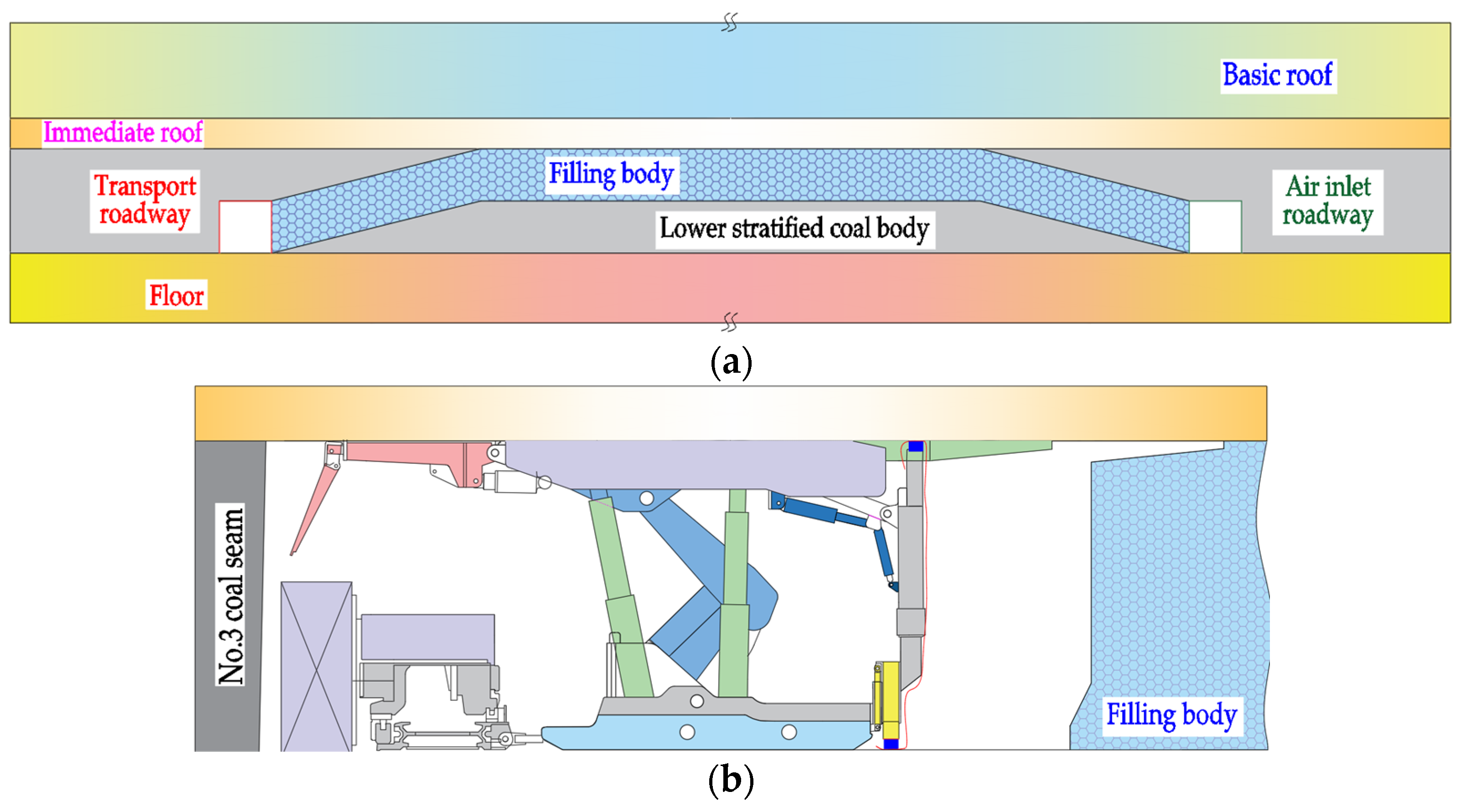
The traditional caving method of coal pressing from floor to roof under buildings, railways, and water bodies can easily induce rock pressure shocks, water resource losses, surface subsidence, damage to building and transportation facilities, and prominent negative environmental effects (see
Figure 1a). Traditional caving methods will face huge social and economic problems [
6,
7,
8]. In contrast, paste backfill mining is used [
9,
10,
11,
12,
13] (see
Figure 1b) after coal resources are mined, and backfill bodies replace mined coal resources in time to carry the bulk density of overlying strata. Overlying stratum movement and mine pressures under the bearing system are inevitably different from those of traditional caving mining.
Therefore, overlying stratum movement and mine pressure weakening in paste backfill mining should be studied to understand the fractures of the backfill mining roofs, crack development in overlying strata, and the characteristics of surface subsidence and deformations after backfilling. This will all provide a theoretical basis and technical support for designing green paste backfill mining, selecting key backfill equipment, and promoting support parameters and ecological mining.
Researchers have studied the movement law of overlying strata and the appearance of mine pressures in backfill mining. Wang et al. [
14,
15] studied overlying stratum movement and the law of surface subsidence in deep wells and ultra-high water filling mining by combining various methods. The failure characteristics of overlying strata and the occurrence law of mine pressures were studied in the context of when the ultra-high water backfilling working face passes through the fault. Zhang et al. [
16,
17,
18,
19] combined the mining conditions to study the energy accumulation and stress concentration of coal seams under different filling methods and filling rates. The critical conditions for the occurrence of dynamic disasters in mines were determined, and the anti-scour mechanism of backfilling and mining was proved, which ensured the safe and efficient production of impacted mines. Xie et al. [
20,
21] established a mechanical model of the main-roof elastic-foundation sheet for backfill mining. The difference theory and the breaking criterion of the main bending moment were used to study the influences of elastic foundation coefficients of the filling body, the thickness of the main roof, elastic moduli, and boundary elastic foundation coefficients on the main bending moment and the rupture regularity of the main roof. The control mechanism of the immediate-roof state of solid-filling mining was revealed, and the precise control method was proposed to ensure roof stability.
Jia et al. [
22,
23,
24,
25] used the inclined borehole detection method to conduct long-term and multiple fixed-point detections at goaf roof according to the working face conditions of gangue filling in a mine in Tangshan. The distribution law of mining fractures in the roof was quantitatively described by the fracture density. A similar model test method was used for auxiliary analysis, which revealed the development process of roof fractures in gangue backfill mining. It provides a research basis for roof failures in backfill mining. Petlovanyi et al. [
26,
27,
28,
29,
30] studied the characteristics of surface subsidence with different filling mining methods, filling rates, and coal seam thicknesses to establish a numerical simulation model. Simulation results were verified by field measurements. The influence of mine gangue filling mining on surface buildings was evaluated with relevant deformation indices, which laid a foundation for studying surface subsidence in solid-filling mining. Sun et al. [
31,
32,
33,
34] used numerical simulation software and combined on-site industrial practice to study stress concentration and energy accumulation in the stope under different filling methods and filling rates. When the filling rate was increased, stress, energy accumulation, and mine pressures were weakened. Both the filling-to-collapse ratio (with a certain coal pillar) and the collapse-column ratio (with a certain length of the filling section) affected mine-pressure weakening, and the collapse-column ratio had a greater impact.
Researchers have studied the weakening law of rock pressures of overlying stratum movement in backfill mining. Most of the studies focused on thin and medium-thick coal seams instead of overlying stratum movement and the law of mine pressure weakening in backfill mining of thick coal. Combining the engineering geological conditions of the first working surface that Shanxi Gaohe Energy filled, the work studied the law of overlying stratum movement and mine-pressure weakening in thick-coal-seam filling and mining. It provides a theoretical basis for designing backfill mining roadway support, controlling mine pressures, selecting backfill support, and promoting the green mine concept.
2. General Situation of Filling in Lu’an and the Properties of Related Equipment and Materials
Lu’an Group is located in Changzhi City, Shanxi Province, China, and there is a serious problem of mine pressures under buildings, railways, and water bodies. The 12 coal mines in the headquarters have the mine pressure of 3.31 billion tons, which accounts for 37.7% of industrial reserves. Mine pressures seriously restrict the long-term sustainable development of Lu’an Group. Lu’an Group’s Gaohe Coalmine Field is 13.4 km long from north to south and 4.9 km wide from east to west. Coal seam 3# is the most extensively mined. It has an approved production capacity of 7.5 million t/a and a service life of 40 years. The mine is connected to Changzi County in the west, Wuzhen Road in the north, Taiyuan-Jiaozuo Railway, National Highway 208, Zhuozhang River, and Changjin Expressway running through the north and south. There are 38 coal-pressing villages, and the total amount of coal-pressing in the whole mine is as high as 372 million t. If the problem of coal mining under buildings, railways, and water bodies cannot be solved, the mine will face the dilemma of resource depletion.
To this end, Gaohe Energy adopted “high-efficiency paste-filling mining” to solve coal pressing under buildings, railways, and water bodies; and the E1302 working face was first selected for filling. The coal seam buried depth of the E1302 working face was 404–425 m. The average buried depth was 415 m, the average coal seam thickness was 6.38 m, the uniaxial compressive strength of the coal mass was 9.49 MPa, and the average inclination angle of the coal seam was 2°. Above the coal seam had a 1.82 m thick mudstone immediate roof and 5.25 m sandy mudstone main roof. The east of the working face was the mine boundary; the west was the goaf of the E1303 working face; the south was the goaf of the E1302 top coal caving working face; the north was the +450 m horizontal east-wing roadway.
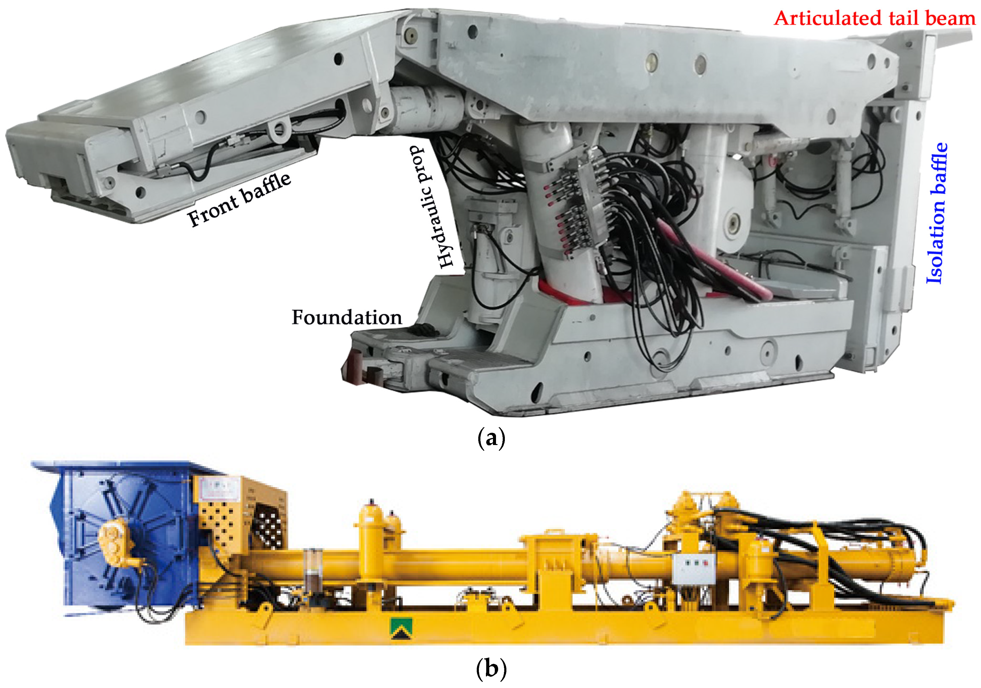
The roof of the working face was stable, and the isolation process of the filling area behind the working face could quickly achieve high-efficiency paste filling and mining. Secondly, the filling material has good fluidity and stability after setting and could carry the bulk density of overlying strata. Finally, the long-distance pumping of gangue gypsum filling materials should be stable and smooth. ZC8500/22/40 paste-filling hydraulic support was developed (see
Figure 2a for filling support) to ensure the roof stability of the filling surface and the quick and safe completion of the filling and isolation work. Support was designed with a rear-hinged tail beam without descending, which could ensure the safety of operators in the area to be filled. The isolation structure was optimized, and the dedicated isolation structure could realize the rapid isolation and sealing of coal-seam roof and floor, which doubled the filling efficiency.
A large-displacement, high-pressure (19 MPa) paste-filling pump (see
Figure 2b) was developed to ensure the stable and smooth long-distance pumping of gangue gypsum filling materials. The pumping capacity reached 250 m³/h, and the output pressure exceeded 19 MPa. The impact pressure was low during reversing, and the failure rate was low after working for a long time. Self-flow could be realized in the self-standing pipe in the filling pipeline. The filling pump mainly provided power for paste flow in the horizontal pipeline, and the normal pumping pressure was 1–2 MPa. When the filling pipe reached full pipe flow (300 m
3), the pumping capacity was increased to nearly 4 MPa. At this time, the oil pressure of the filling pump reached 8–10 MPa, which was far from designed power. The large displacement filling pump could ensure the stable and smooth pumping of filling slurries.
According to the
Standard for the Test Method of Mechanical Properties of Ordinary Concrete (GB/T 50081-2002) and
Methods for Determination of Physical and Mechanical Properties of Coal and Rocks (GB/T 23561.1-2009) [
35,
36,
37,
38,
39,
40,
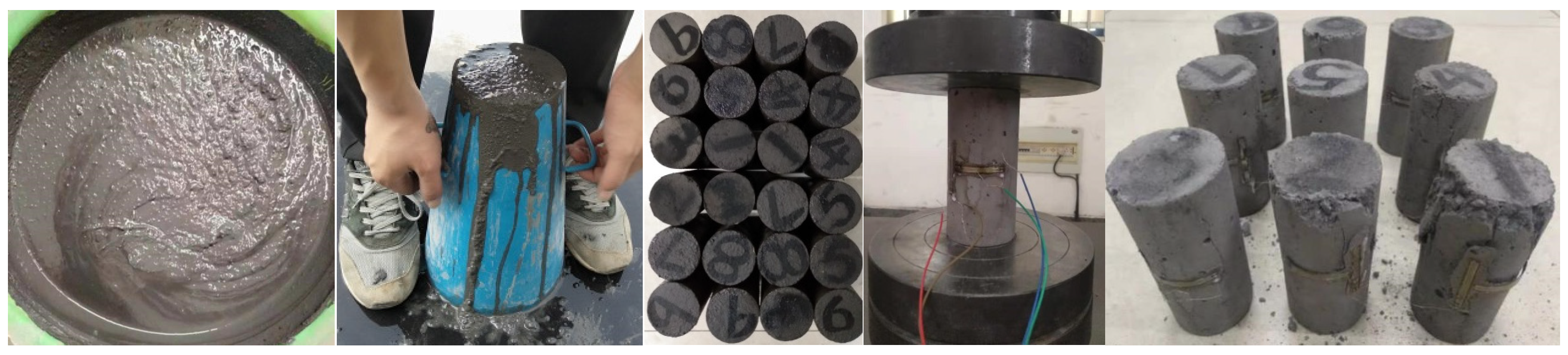
41], multiple proportioning tests were carried out after sampling at Gaohe Energy Filling Station to ensure that the filling materials had good fluidity and could bear the bulk density of overlying strata after setting. Slump and expansion tests were performed on paste-filling slurries before preparing specimens, and uniaxial compression tests were performed on specimens of different ages after preparing specimens (see
Figure 3 for the test process).
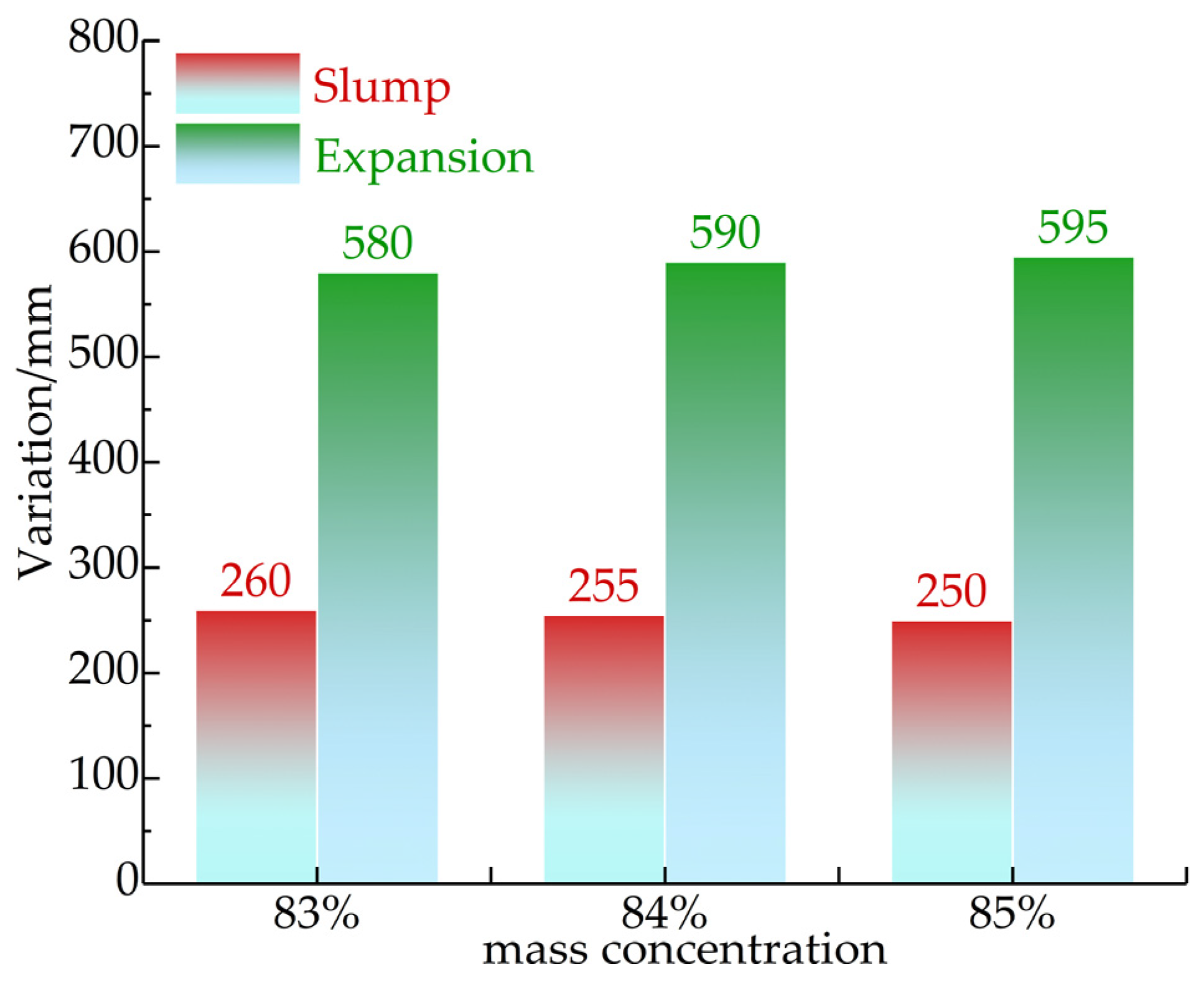
Mass concentrations tested for the gangue fluidity test were 83, 84, and 85% (see
Figure 4). The slumps of filling material slurries was 255–265 mm, and the expansion of filling material slurries was 510–620 mm. When the slumps of gangue gypsum body materials were greater than 240 mm, they could be pumped and transported through pipelines. The mass concentration of gangue gypsum used by Gaohe Energy was about 81%, so the flow performance of Gaohe gypsum filling materials could meet the requirements of engineering practice.
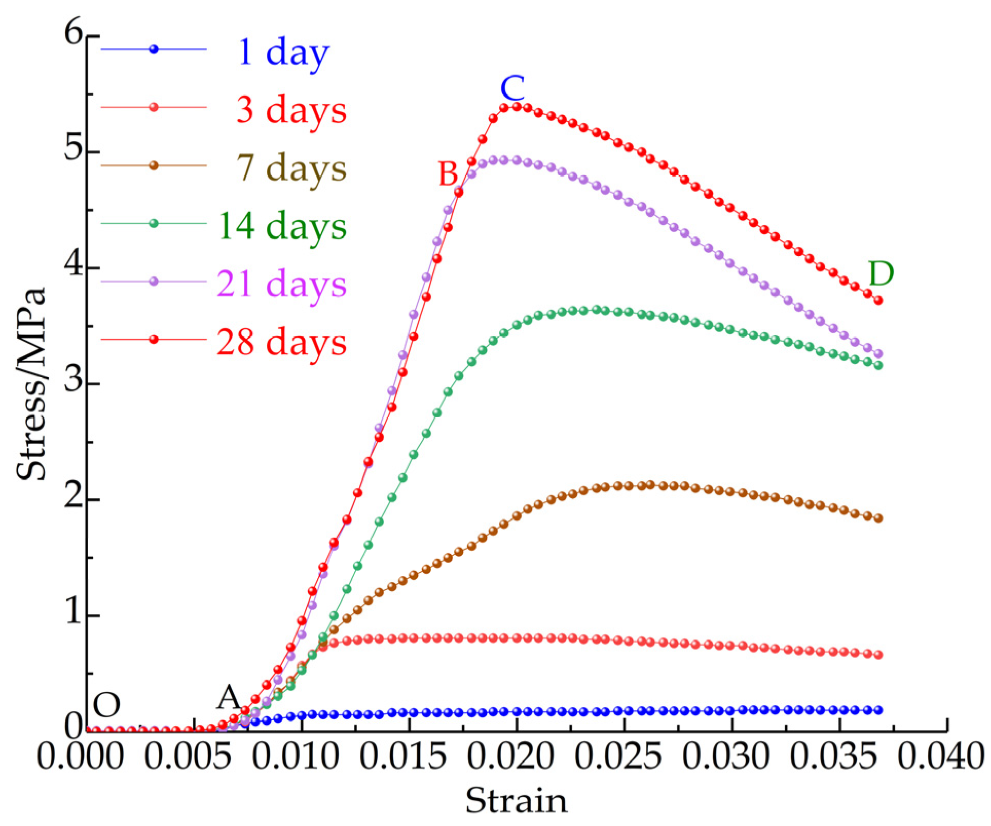
Specimens were prepared and tested at the ages of 1, 3, 7, 14, 21, and 28 d, and the total stress–strain curve of the gangue gypsum body material was drawn (see
Figure 5). The stage characteristics of the stress–strain curve at each age had high consistency, and the stress–strain curve could be divided into four stages of OA, AB, BC, and CD. The OA section was the initial compaction stage; the AB section was the elastic stage; the BC section was the yield stage; the CD section was the failure stage. The peak value of the curve gradually increased with age, and the slope of the AB section increased gradually. The uniaxial compressive strength and elastic modulus of the gangue gypsum body increased gradually with age. The ages of 21 d and 28 d were nearly coincident, indicating that the elastic modulus of the gangue gypsum body increased very little after 21 d. The uniaxial compression test curve was similar to that of rocks, and uniaxial compressive strength was 5.45 MPa, which could bear the bulk density of overlying strata.
The coal mass mined in Lu’an Mining Area is coal 3#, and the thickness of the coal seam is relatively large. If full-thickness backfill mining is used at one time, the height of the backfill area is large, and the stability of backfill materials before the initial setting is difficult to control. In addition, the stability of the coal walls of the working face with large mining height is not easy to control. Therefore, layered filling mining can be selected—according to the thickness of the coal seam of coal 3#, the coal mass can be mined in two layers, that is, upper-layered and lower-layered mining.
If upper-layered mining is adopted, the lower-layered coal mass shall be mined first. Mining causes a large disturbance to upper-layered coal, and broken coal falls after the disturbance. When the upper layer is mined again, the coal mass is broken, and the control of coal walls and roadway retention is relatively difficult. If lower-layered mining is adopted, the upper-layered coal mass is mined, and the disturbance to the lower-layered coal mass is relatively small. Backfill is condensed into a whole after mining, and the coal wall and paste false roof are relatively stable during mining lower layers, which is conducive to safe and efficient mining.
Figure 6a shows the layout of the working face during downward layered mining.
The upper and lower working faces share a set of mining tunnels in layered filling mining. When the upper layered working face is mined, there is a 30 m climbing area at both ends of the working face. Two mining tunnels are reserved for lower-layer mining (see
Figure 6b for the mining process of the backfilling working face). The coal mining team carries out processes such as coal cutting, coal loading, coal transportation, and rack shifting with the shearer cutting coal as the main line. When there is enough area behind the working face for filling, the filling shift first completes roof isolation. Meanwhile, the ground filling station uses mortar to push water and gangue slurries to push mortar. The mortar along the filling pipe reaches the front of the work, and roof isolation has been completed. It enters the normal filling stage from the initial filling stage after the gangue slurries appear in the working face.
3. Roof Stability Analysis of Backfill Mining
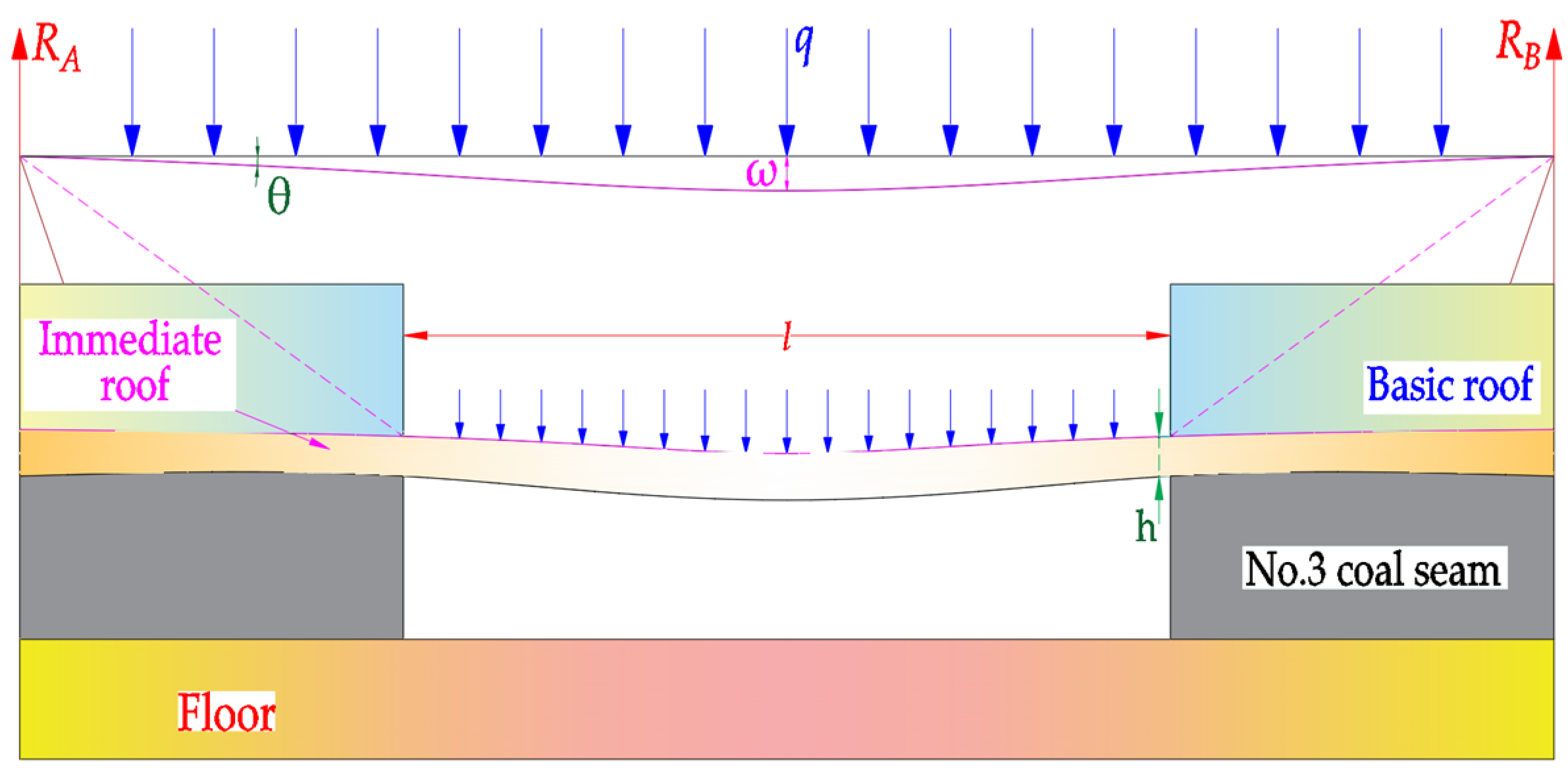
Roof stability control is the key to whether the paste-filled working face can be recovered safely and efficiently. Roof stability also directly affects the overlying stratum movement and surface subsidence. The key to roof stability control is the breaking step distance of the roof and the bending deflection during breaking. There is a lot of free space in the area where the original coal mass is located after mining, and stope stress is redistributed. The load borne by mining overlying strata generally includes the self-weight and the load generated by overlying strata. It is generally assumed that the rock load is uniformly distributed for the convenience of analysis. Overlying strata interact with evenly distributed loads, and upper and lower strata deform synchronously to form a composite beam structure [
42]. The roof of the coal seam forms a fixed beam structure under the support of the coal mass behind incision and the coal mass in front of the working face. The fixed beam bends and sinks under overlying strata and their self-weights (see
Figure 7 for the stress situation).
It is necessary to ensure roof stability during the mining process of the working face (see
Figure 7) for safe and efficient mining. Bending subsidence
ω of the working-face roof should be less than the equivalent mining height, and roof stress
q can be calculated according to the composite beam theory. Opposite force
RA and
RB are formed at both ends of the clamped beam in the process of bending and sinking the clamped beam. The symmetry of the clamped beam is used to obtain Equation (1) [
43,
44].
Shear force
Qx in the section at position x from the left end of the beam is
Bending moment
Mx of this section is
where
MA is the bending moment at the left end.
, which is substituted into Equation (3) to obtain
When x = 0 and l, . When , .
The deflection curve of a clamped beam is approximated by differential equation
. ω is solved to obtain
where
E is the elasticity modulus, GPa;
I the section inertia, m
4;
I the sectional inertial distance, m
4;
l the beam width, m;
h the beam height, m.
Equation (4) is substituted into Equation (6) to obtain
When
x = 0 and
l,
= 0. C
1 = 0 and C
2 = 0, so
When the maximum deflections is , .
According to the maximum tensile stress intensity criterion of material mechanics, the ultimate span of the beam without fractures is
where
l is the safe span of the basic roof, m;
h the roof thickness, m;
σ the tensile strength of the roof, MPa;
n the safety factor;
q the load of the basic roof, MPa.
According to the theoretical calculation of composite beams, the load on the immediate roof is 0.042 MPa. Laboratory tests show that tensile strength σ of the immediate mudstone roof is 1.50 MPa; the elastic modulus E is 5.78 GPa; thickness h of the mudstone immediate roof is 1.82 m. Considering the safety of backfilling mining, the safety factor n is 1. The initial breaking step distance of the immediate roof is 19.8 m, and the maximum bending deflection is 0.29 m. Gaohe Energy adopts layered mining, and the thickness of the upper layer is 3.2 m. If the stability of the direct roof is guaranteed without breaking, theoretically, the layered filling rate should be greater than 91%, and the overall filling rate should be greater than 95.4%. In the following, it is proposed to further study the bending fractures of roof under caving mining and different filling rates utilizing UDEC discrete element numerical simulation software. The law of overburden migration, fracture development, and mine pressure weakening in thick-coal backfill mining should be explored.
4. Simulation of Overlying Strata Movement and Mine-Pressure Weakening in Thick-Coal Backfill Mining
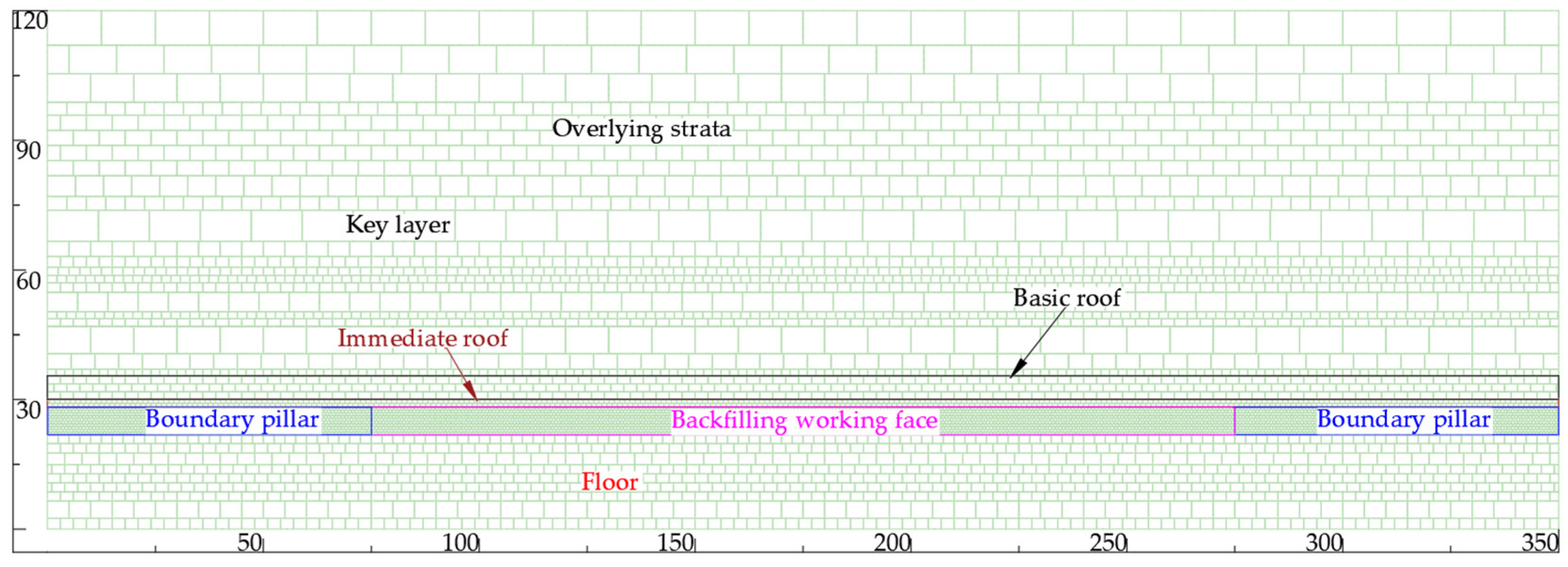
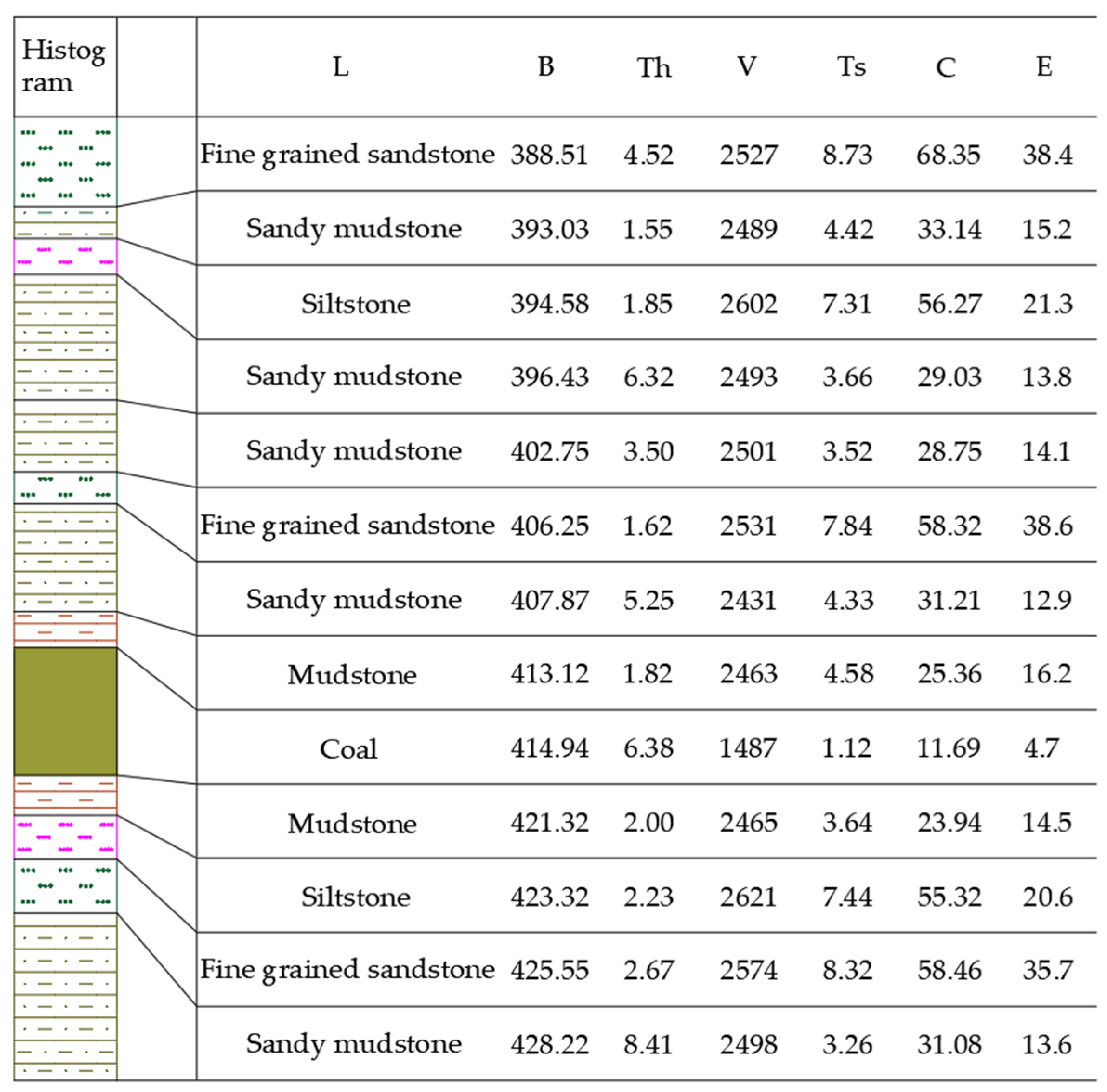
According to the engineering geological overview of the first E1302 working face that Gaohe Energy filled, a numerical simulation model with a width of 350 m and a height of 120 m was established using discrete-element numerical simulation software (UDEC 6.0 version). Seventy-five meter boundary coal pillars were left on the left and right sides of the model to eliminate the boundary effect. The stress of 7.6 MPa was applied to the model roof to simulate the bulk density of overlying strata, which constrained the movement of both sides and floor. The 200 m wide area in the middle of the model was the mining area.
Figure 8 and
Figure 9 show the specific simulation model and the parameters of rock strata, respectively.
The mechanical parameters of rock strata were assigned after the modeling was completed. The working face consistent with the site was excavated step by step after the model reached the equilibrium state again, and the support unit was used to simulate the support. The support units of the previous step were removed during the excavation of the next step. Simulation content concluded the bending failure process of the working face roof under caving mining and filling rates of 90 and 95%. The fracture development of overlying strata and the characteristics of layered-filling mine-pressure weakening were simulated by filling and caving methods after a reasonable filling rate was determined.
4.1. Simulation Analysis of Roof-Fracture Failure in Backfill Mining
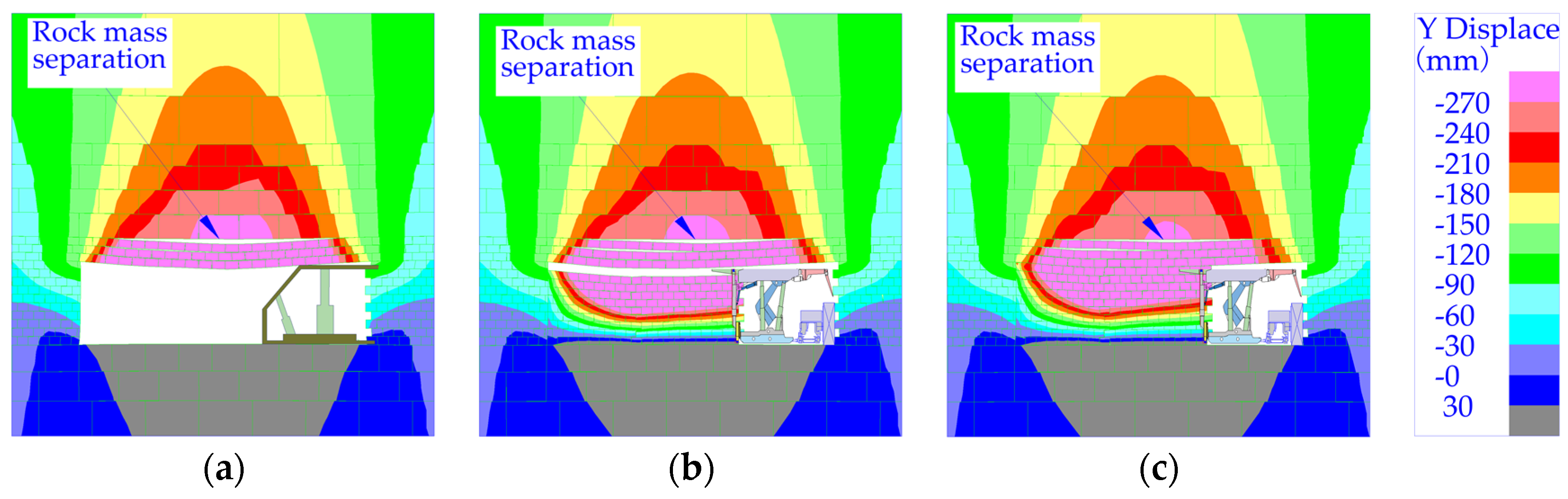
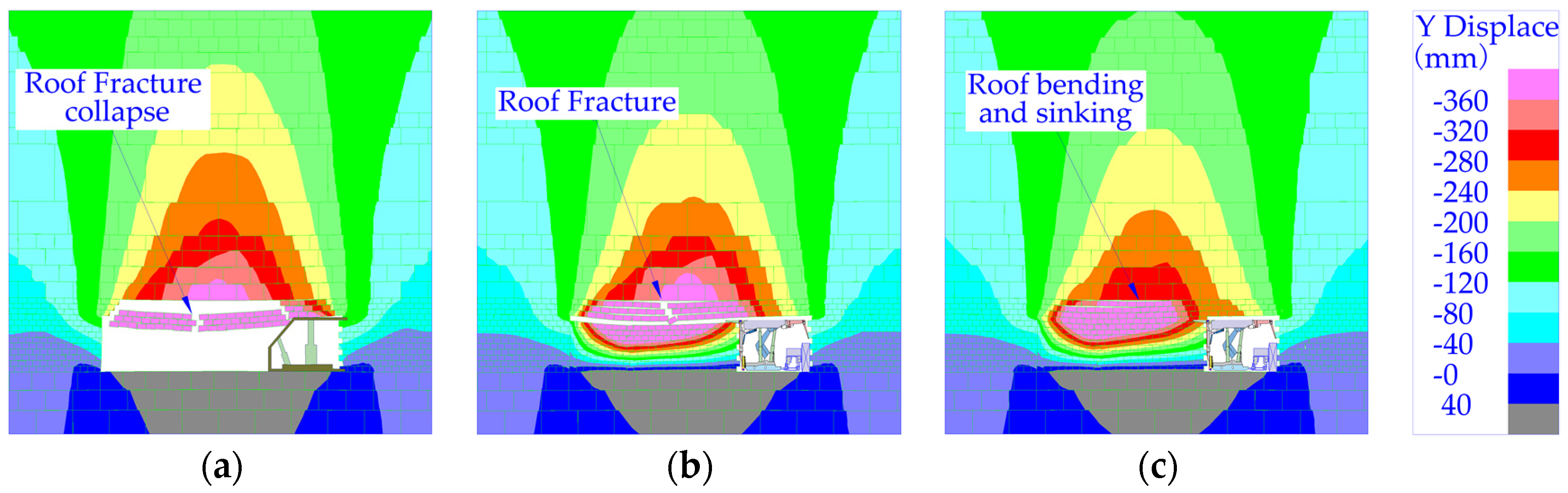
Figure 10a and
Figure 11a show the bending, subsidence, and damage of the roof during the advancing process of the working face under the caving method.
Figure 10b–c and
Figure 11b–c show the bending, subsidence, and failure process of the roof during the advancement of the working face when the filling rates are 90 and 95%, respectively.
The immediate-roof thickness of the working face is 1.82 m, and the thickness of the main roof is 5.25 m. The immediate roof bends and sinks in both caving mining and filling mining during the advancing of the working face. The immediate roof is bent and separated from the main roof due to the large thickness of the main roof and the relatively small amounts of bending and sinking. There is a lot of free space under roof after coal masses are mined in the case of caving mining. The immediate roof breaks and collapses during moving forward.
When the filling rate is 90%, the equivalent mining height below the working face is 0.64 m, and fractures and caving can also occur during the advancement of the working face. When the filling rate is 95%, the equivalent mining height is 0.32 m, which exceeds the limit breaking bending deflection of the immediate roof of 0.29 m. However, the filling body is contacted in time after roof bends and sinks, and there is no room for breaking. Therefore, the immediate roof will not break and slump, which can ensure roof integrity. The filling rate should be greater than 95% to ensure the stability of backfill-mining roof. When the filling rate is 95%, although the roof does not break down, fractures still develop.
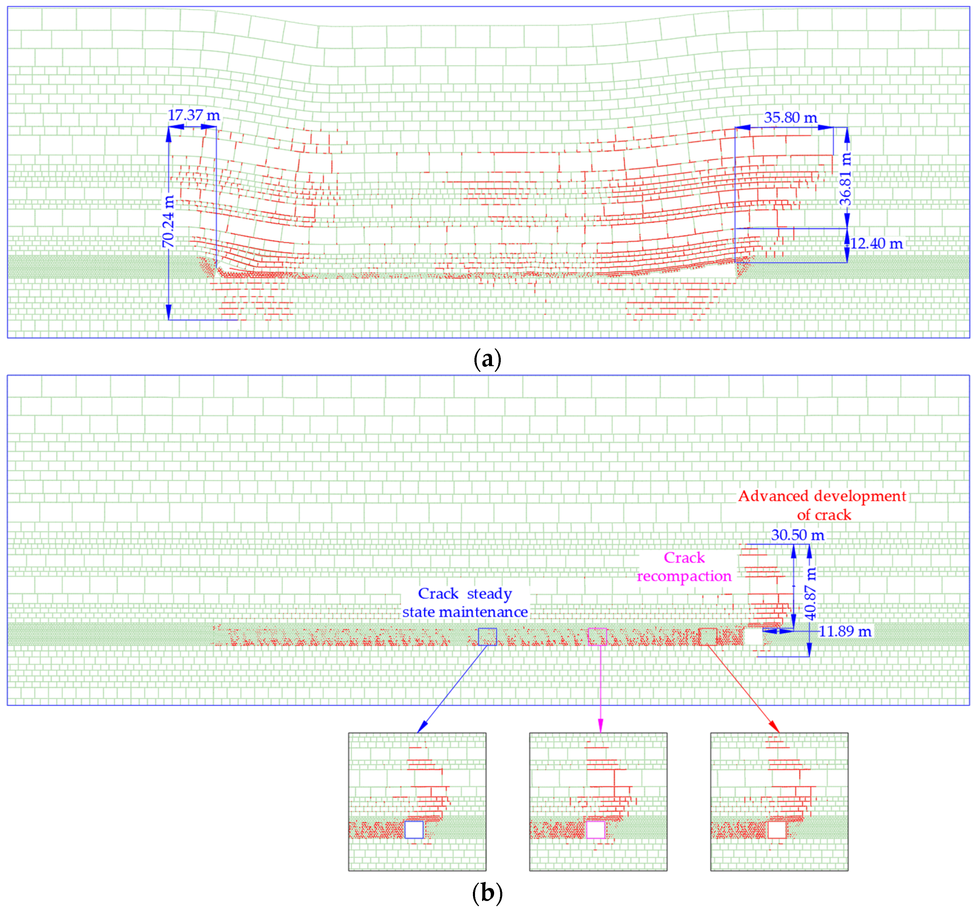
Figure 12 shows fracture development in caving mining and filling mining.
Fractures in overlying strata are divided into open and slip ones during the mining process of the working face. Opening fractures are caused by the separation and fracturing of overlying strata; slip fractures are caused by slip dislocations in strata. Rock masses above the working face produce a large number of open fractures during the slewing and subsidence process (see
Figure 12a). However, a large number of slip fractures are generated during overlying stratum movement above the rear side of the working face. A large number of open fractures above the middle area of the goaf are gradually compacted during the subsidence of overlying strata, and the total amount of fractures is small. Both open and slip fractures are develop above the incision. Fractures have developed to 17.37 m behind the working face in a “saddle shape” as a whole. There are mainly open fractures above the working face developing in a “sail shape” during the advancing process of the working face in the case of backfill mining. The advanced working face developed at 11.89 m, and the fracture height above the coal seam is 30.5 m.
The backfill body replaces the mined coal mass in time and directly contacts the backfill body after bending and sinking without breaking. The movement of overlying rocks is restricted after contacting backfill, and fractures generated by overlying strata at the working face are re-compacted. Therefore, fracture development in filling and mining can be divided into the following stages: advanced fracture development, re-compaction of fissures, and steady maintenance of fractures. Advanced fracture development presents a “sail-shaped” progression. The fracture-recompacting area is above the rear side of incision, and the rear fractures only appear in main-roof strata.
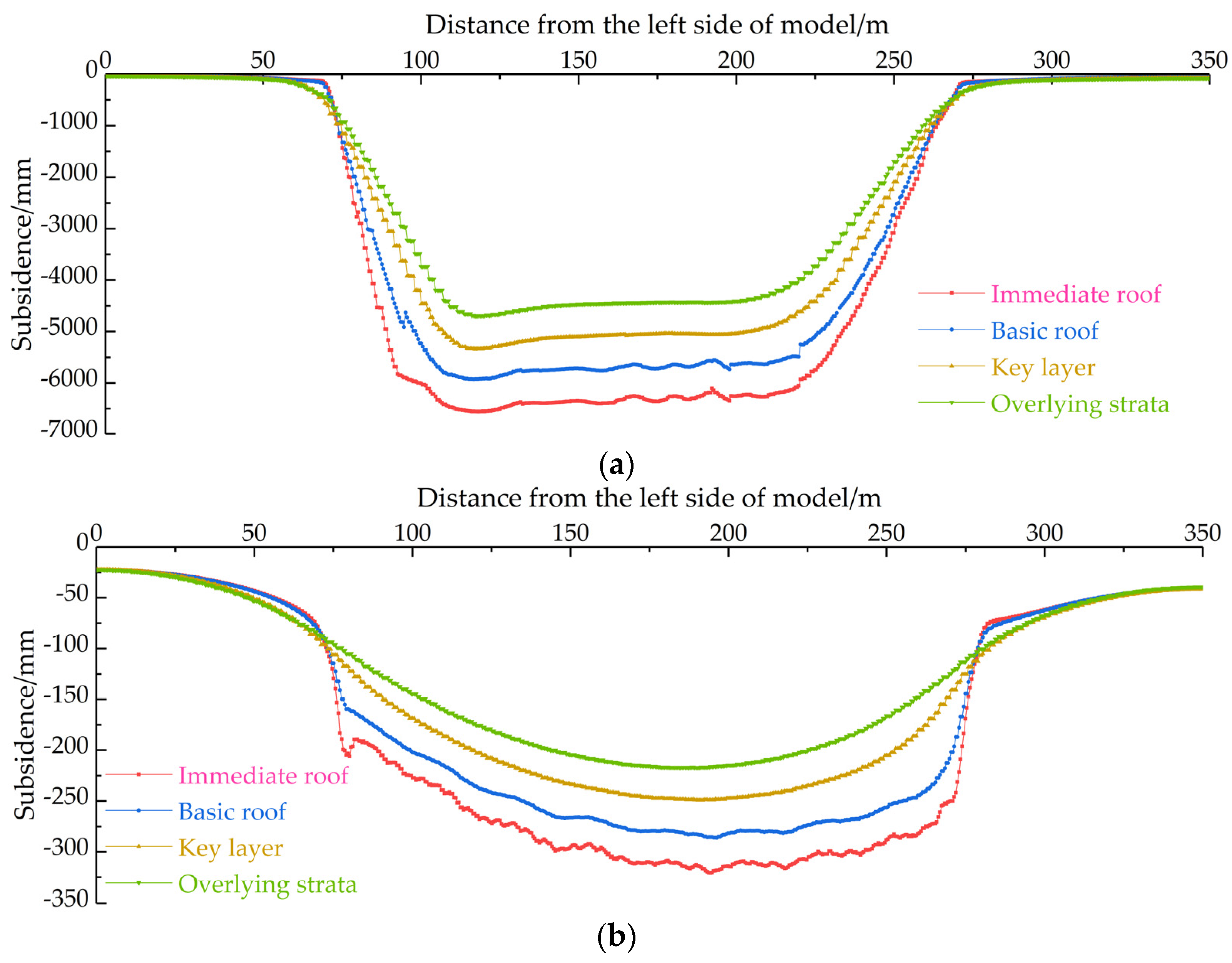
Figure 13 shows the movement curves of overlying strata after mining with different mining methods.
Entire immediate roof cave-in occurred after the caving mining working face was recovered, and the maximum displacement is 6335 mm. Immediate roof has a certain crushing effect after the collapse, and crushed rock masses of immediate roof after crushing and swelling can reduce the falling space of main-roof rock masses. Therefore, the maximum subsidence of main roof is 5914 mm, and the maximum displacements of the key layer and overlying strata are 5046 and 4407 mm, respectively. When backfill mining is used, the equivalent mining height is 320 mm, and the maximum subsidence of the immediate roof is 315 mm. The curved and subsided immediate roof controls the overlying stratum movement of the main roof. The immediate roof only sinks without distending, and the maximum subsidence of the main roof is 282 mm. The maximum subsidence degrees of the key layer and overlying strata are 243 and 226 mm, respectively. Above overlying strata is the quaternary unconsolidated formation, and the unconsolidated formation sinks synchronously with the subsidence of overlying strata. The subsidence coefficient of simulated caving mining is 0.688, and it is 0.035 when the filling rate is 95%.
4.2. Simulation of Advanced Stress Distribution and Weakening Law
Overlying strata above the working face form a cantilever beam structure which showed rotary sinking after the working face was mined. Coal masses in front of the working face were squeezed during the process of overburden slewing and subsidence, which resulted in stress redistribution in front of the coal walls of the working face—that is, the leading bearing pressure appeared. As the working face moves forward, the advanced support pressure moves forward. The stress of the coal wall in front of the working face increases, and coal masses are prone to deformations and failure under high support pressures. Therefore, the influences of advanced bearing pressures should be considered in the roof management of the working face and the support of the mining roadway. The section derives the stress data of the coal seam when the roof is managed by the caving method and the stress data of different layers in the case of layered mining. In addition, the distribution law of the advance support pressure in backfill mining has been studied. The caving method was used to manage the advanced roof stress (see
Figure 14a), and
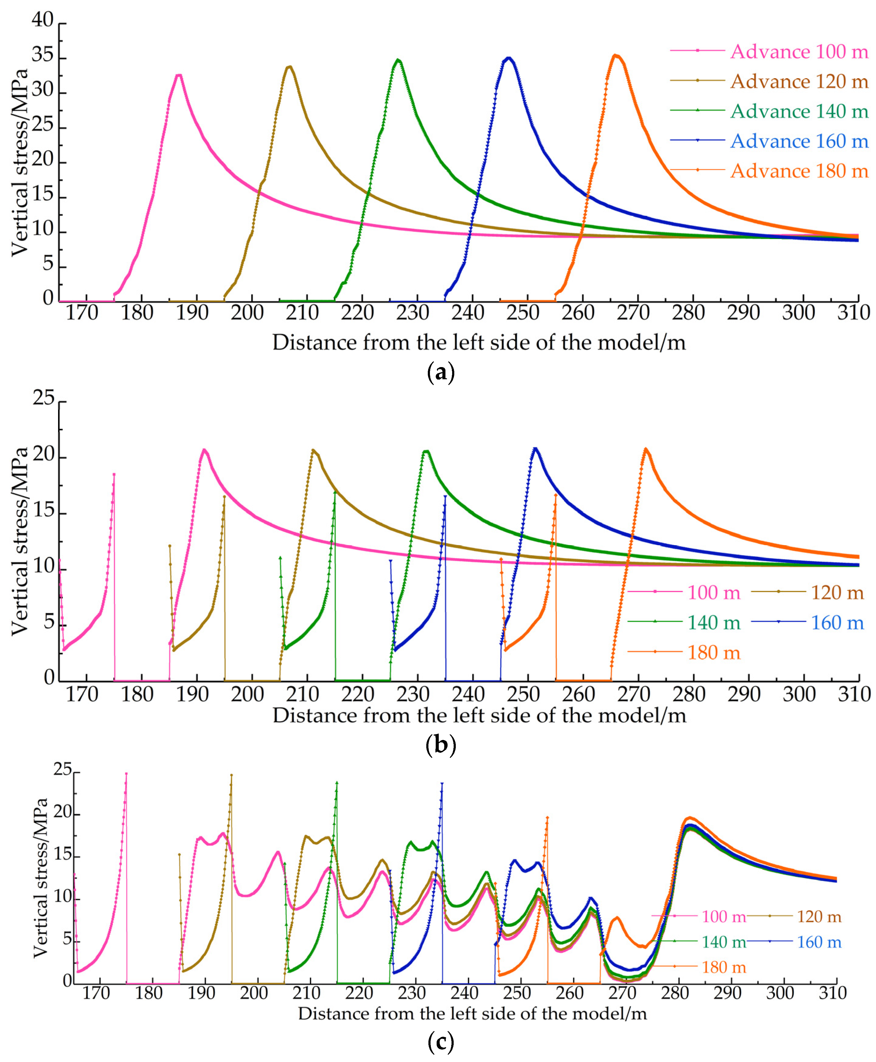
Figure 14b,c show the advanced stress distributions of upper and lower layers, respectively.
Figure 14a shows the advanced stress distribution curve of 100, 120, 140, 160, and 180 m in the caving mining face. When the working face advances by 100 m, the leading stress peak is 33.2 MPa in the simulation, and the peak position is 11.2 m away from the coal wall of the working face. The peak value of the advanced stress of the working face increases to 33.8 MPa after advancing to 120 m from incision, and the peak position is 11.6 m from the coal wall of the working face. When it continues to advance to 140 m from the cut, the peak value of leading stress increases to 34.5 MPa, and the peak position is 11.7 m from the coal wall of the working face. When the working face continues to advance to 160 and 180 m from the cut, the advanced stress peak value rises to 34.8 MPa, and the peak position is 11.8 m away from the coal wall of the working face. Peak stress always remains around 34.8 MPa after moving forward, and its concentration factor is 3.48. The distance from the peak point to the coal wall is unchanged at 11.8 m, and the influence range of the leading stress is about 55.4 m.
The average coal thickness of the E1302 working face is 6.4 m, and the coal mining is carried out by layered filling mining. The upper and lower layers are both 3.2 m deep at an average filling rate of about 95% and a simulated filling rate of 95%.
Figure 14b shows the leading stress distribution during the advancing process of the upper layer working face. When the backfilling face is advanced by 100 m, the advanced stress peak is 20.6 MPa, which is 7.2 m away from the coal wall of the working face. The advanced stress peak is 20.7 MPa after advancing 120 m to incision. The advanced stress peak is 20.8 MPa after advancing 140 m away from incision. When the distance between the working face and incision is greater than 160 m, advanced stress distribution in front of the working face reaches a stable state. The peak value of advanced stress is 20.9 MPa, with a peak value of the stress concentration factor of 2.09 and an influence range of advanced stress of about 48.2 m.
When the lower layered working face advances by 100 m, the advanced stress peak is 17.9 MPa. Advanced stress decreases slightly after advancing to 120 and 140 m. The advanced stress peak value drops below 15 MPa after the working face advances to 160 m. Advanced stress shows a waveform decrease as a whole during the mining process of lower-layered filling. The peak value of advanced stress are smaller than those of the upper-layered working face. When the upper-layered working face is mined and filled, the backfill body is not fully compacted after overlying strata subsidence, which causes the failure of overburden stress to be completely transferred to the lower-layered working face. Meanwhile, parts of the roof have been damaged during the upper layer mining process, and the overhang distance of the cantilever beam is limited. Therefore, the advanced stress is smaller than that of the upper-layered filling. Compared with caving mining, the mining pressure of backfill mining is significantly weakened. The stress concentration factor is weakened by 40%, and the influence range of advanced stress is reduced by 13%.
6. Field Measurement and Analysis
Test points were set up on the surface corresponding to the first test surface of Gaohe backfilling to explore the law of overlying stratum movement and mine pressure weakening in thick-coal, longwall, high-efficiency paste backfill mining. The subsidence and deformation of the working face of the backfill mining were used to study overlying stratum movement in the backfill mining. A borehole stress gauge was installed in the coal mass in front of the working face to monitor the change characteristics of advanced stress during the advancing process of the working face, which could study the law of mining pressure weakening in backfilling.
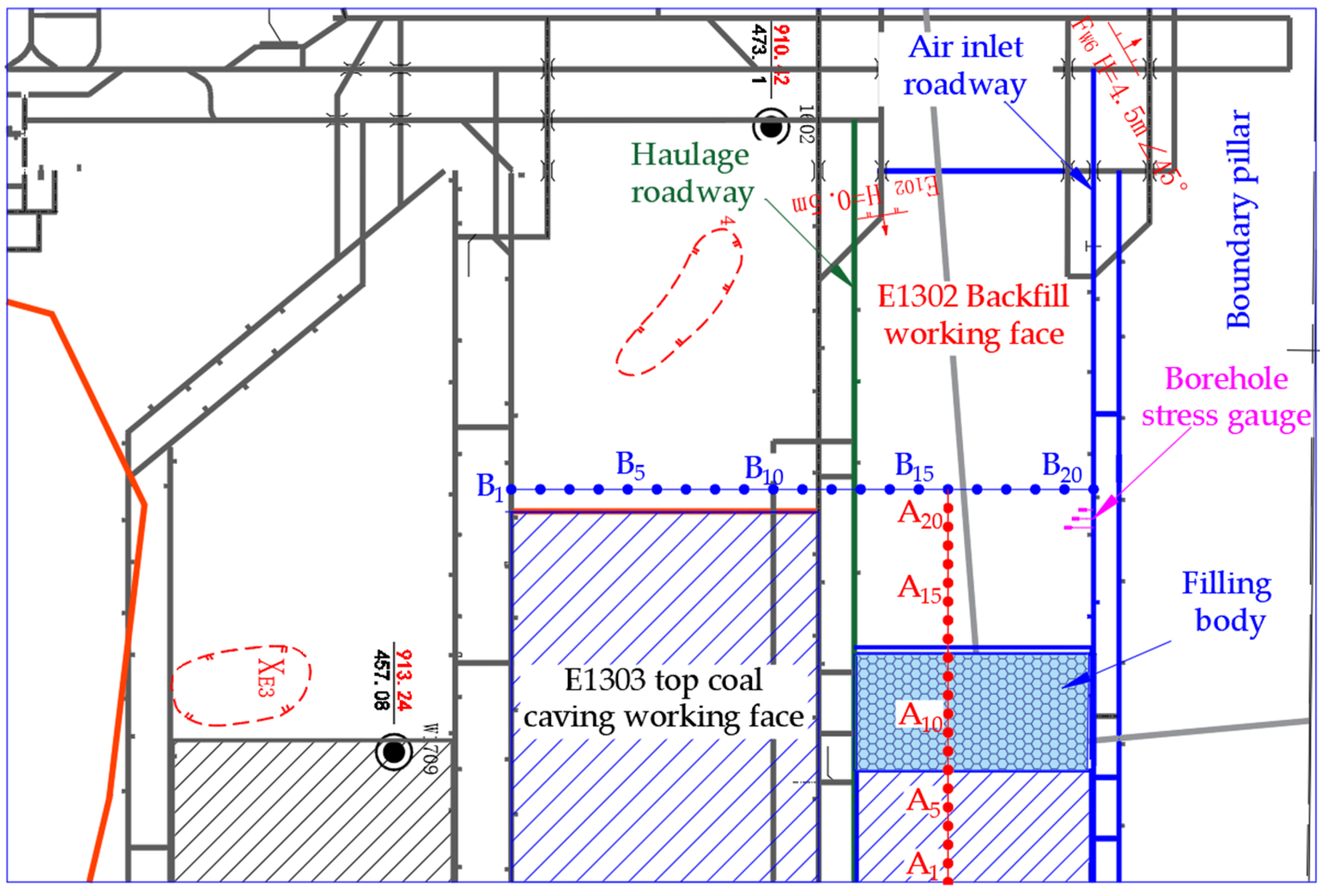
Figure 15 shows the layout of the station.
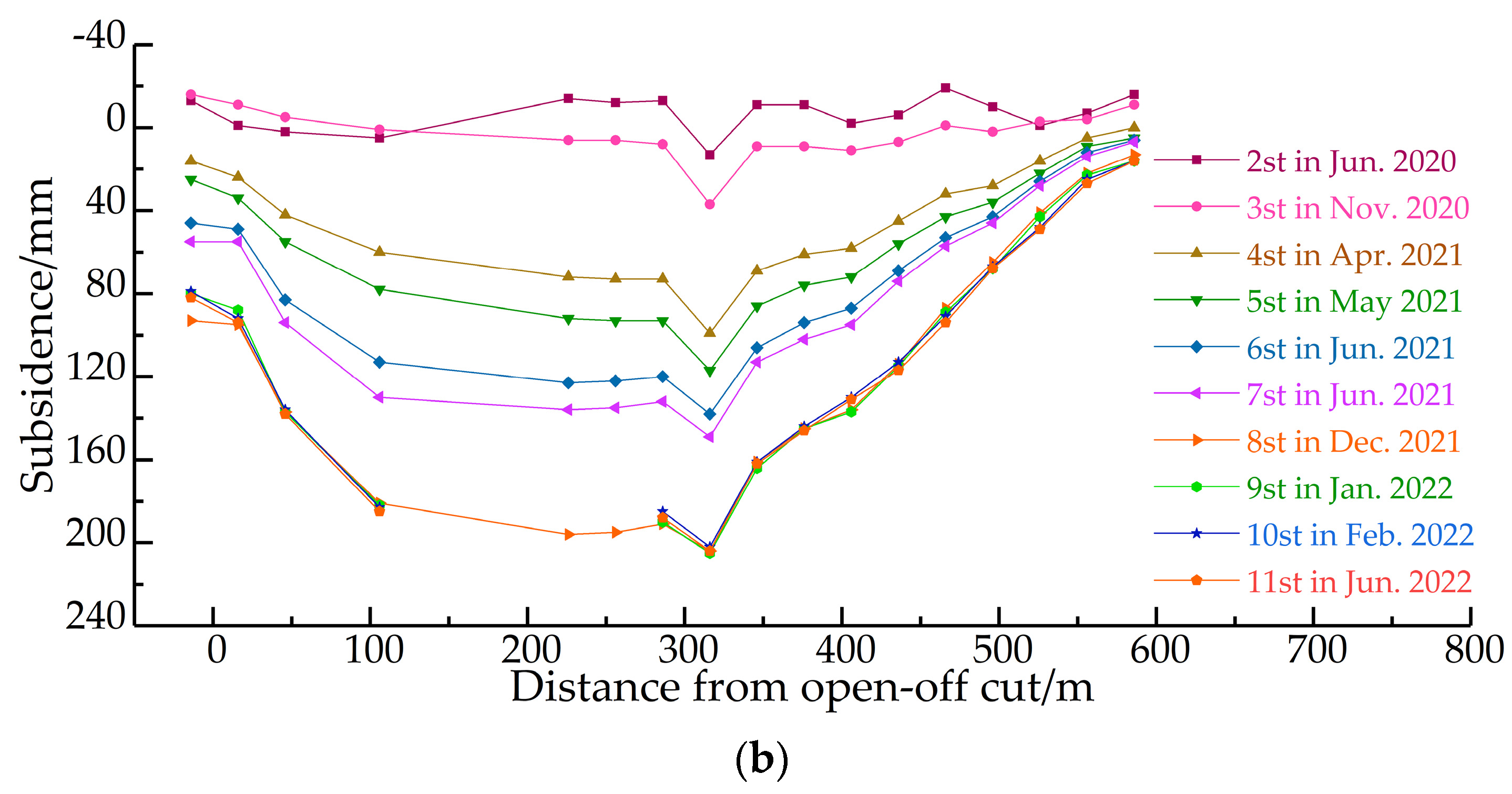
A total of two survey lines were arranged for the surface subsidence monitoring of the filling surface (see
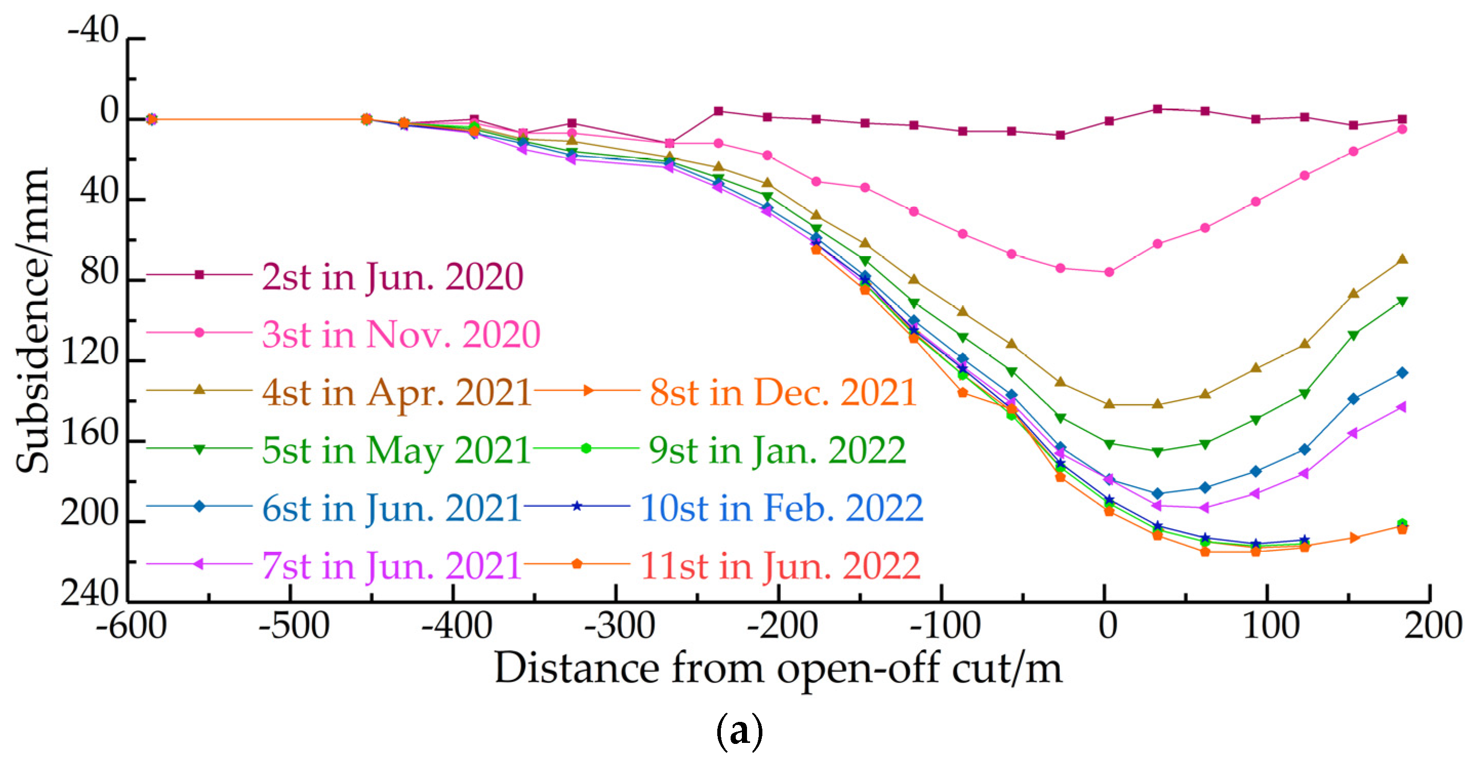
Figure 15). Survey line A is the trend with a length of 600 m. There are a total of 24 measuring points, of which three are control points and 21 are deformation monitoring points. Survey line B is the inclination one with a length of 510 m and a total of 21 deformation monitoring points. There were a total of 11 monitoring iterations from the station’s deployment in December 2019 to the completion of monitoring in June 2022 (see
Figure 16 for deformation monitoring results). The advanced stress monitoring station is arranged in the air inlet roadway to eliminate the influence of the adjacent goaf on stope stress. A total of three borehole stress gauges are present, and the hole depths are 15, 10, and 5 m, respectively; the borehole stress gauge with a hole depth of 5 m failed to leak during the monitoring process.
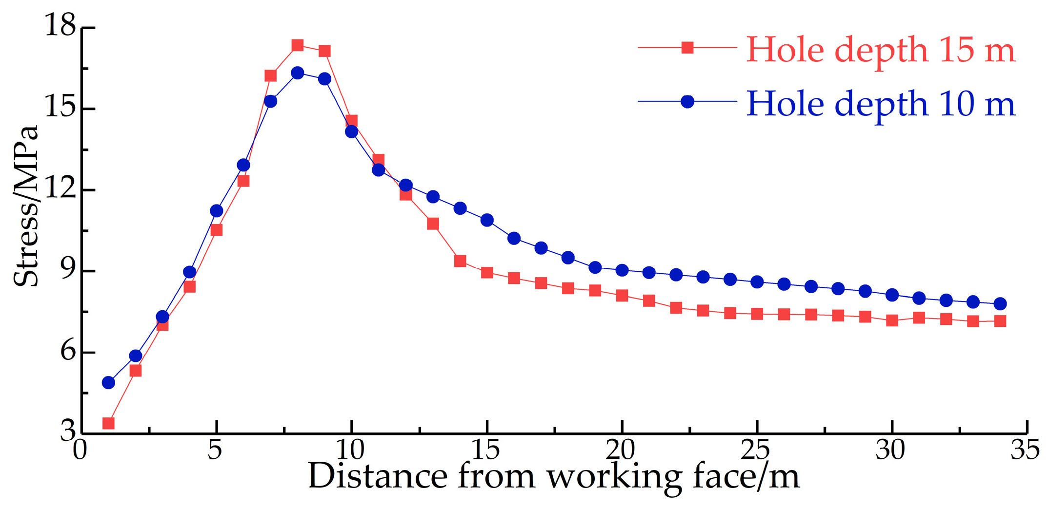
Figure 17 shows specific monitoring results.
Affected by geological factors, the maximum subsidence point of the surface subsidence basin is measuring point B16, and the middle distance from the goaf is 20.75 m. According to the average burial depth of the coal seam of 415 m, the maximum subsidence angle is calculated as . The maximum sinking position of survey line A occurred at measuring point A17, and the maximum sinking amount is 214 mm. The maximum horizontal movement position occurred at measuring point A13, coinciding with a subsidence coefficient of 0.035, the maximum horizontal movement of 80 mm, and a horizontal movement coefficient of 0.37. The maximum sinking position of survey line B occurred at measuring point B16, coinciding with the maximum sinking of 204 mm and a sinking coefficient of 0.032. Maximal horizontal movement occurred at measuring point B21, coinciding with the maximum movement of 144 mm and a horizontal movement coefficient of 0.71. The maximum subsidence of the survey line at the top of numerical simulation’s overlying rocks was 226 mm, and the model roof was a quaternary unconsolidated formation, which sank with the subsidence of the rock stratum. Therefore, simulations were in agreement with the measured data.
The injection of hydraulic oils results in initial stress of about 8 MPa during the layout of the borehole stress gauge. When the layout is completed, the measuring station is about 75 m away from the working face. Combined with the online monitoring of borehole stress and daily mining and charging data, a broken line between borehole stress and working face distance changes is drawn (see
Figure 17). The drilling stress peak is 8 m away from the working surface. The stress gauge of the 10 m-deep borehole is affected by the stress concentration of surrounding rocks of the mining roadway, coinciding with a stress peak value of 17.35 MPa and a stress concentration factor of 2.42. The 15 m depth borehole stress gauge has a stress peak value of 16.34 MPa and a stress concentration factor of 2.08 m. These values are consistent with the simulation results.


