

Assessment of the Blasting Efficiency of a Long and Large-Diameter Uncharged Hole Boring Method in Tunnel Blasting Using 3D Numerical Analysis

Abstract
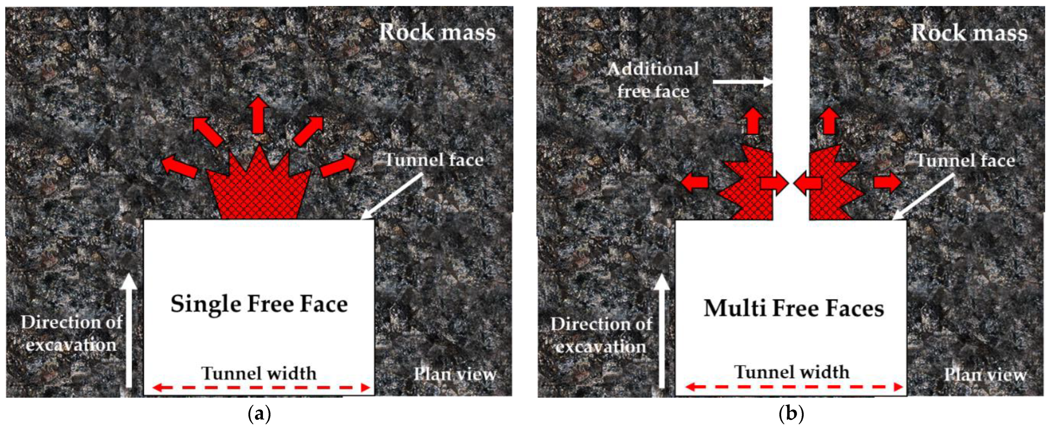
:1. Introduction
2. Long and Large-Diameter Uncharged Hole Boring Method
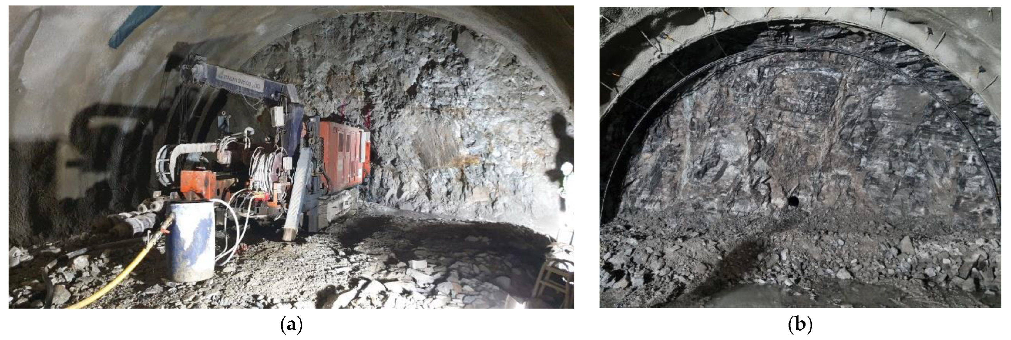
2.1. Introduction to the LLB Method
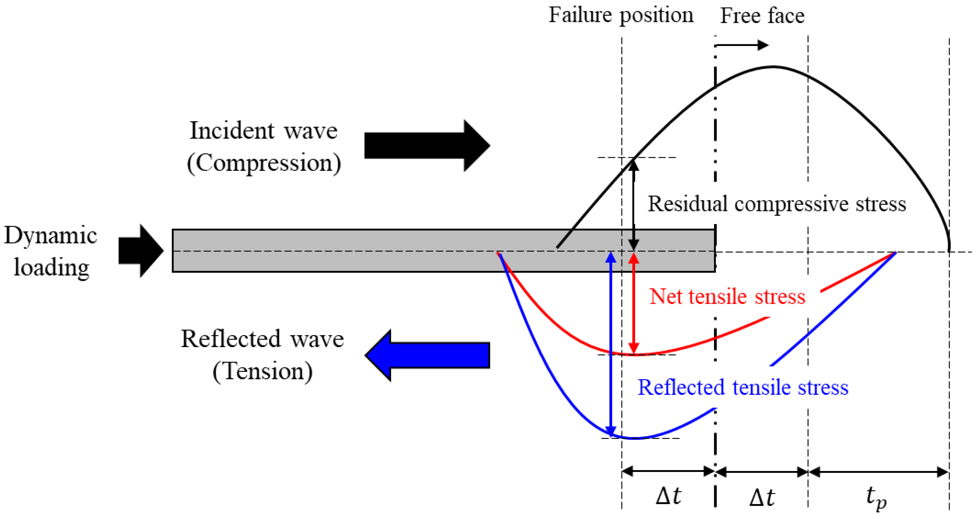
2.2. A Mechanism of Tensile Fracturing by Long and Large-Diameter Uncharged Holes
3. Numerical Analysis
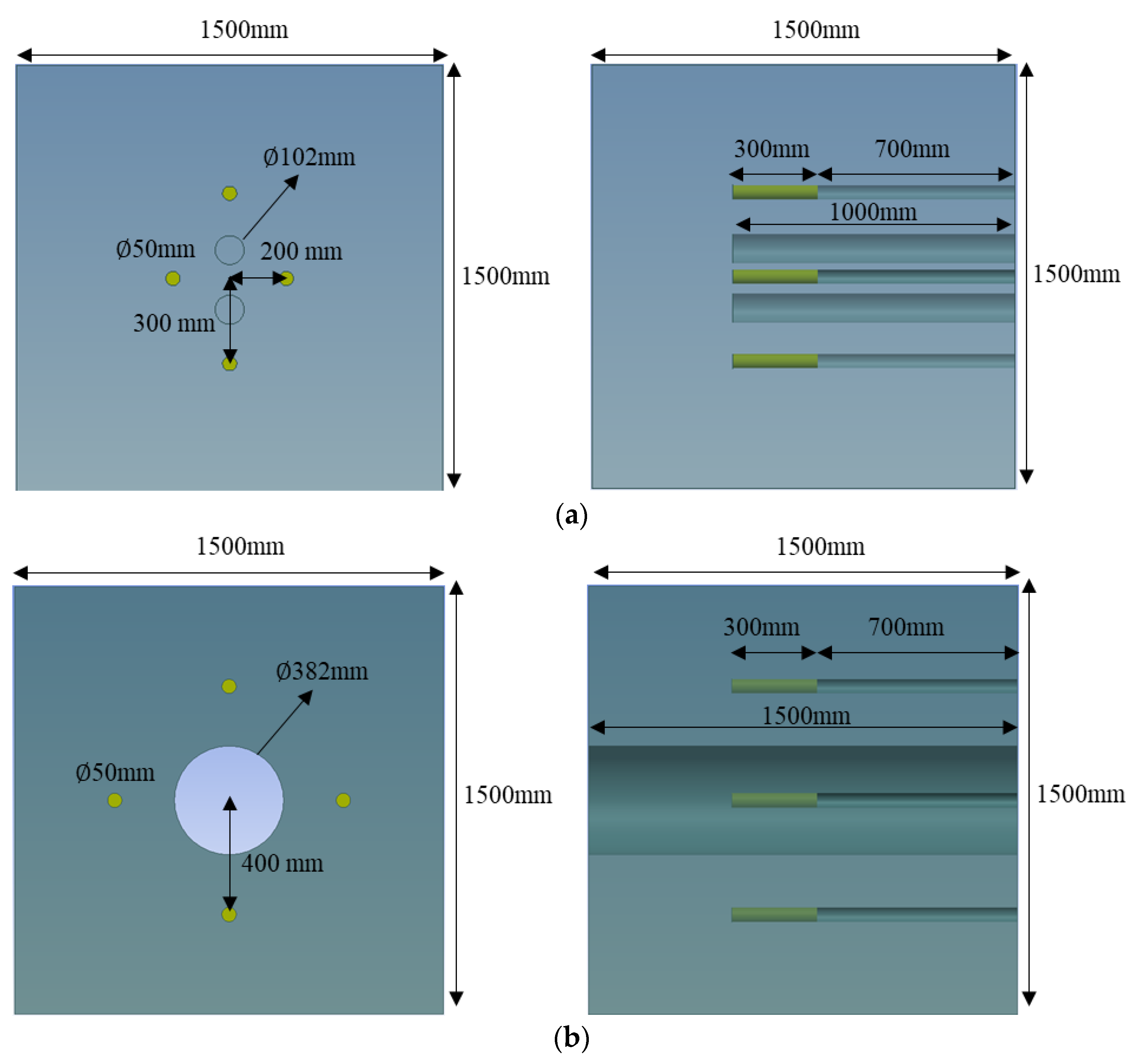
3.1. Analysis Model
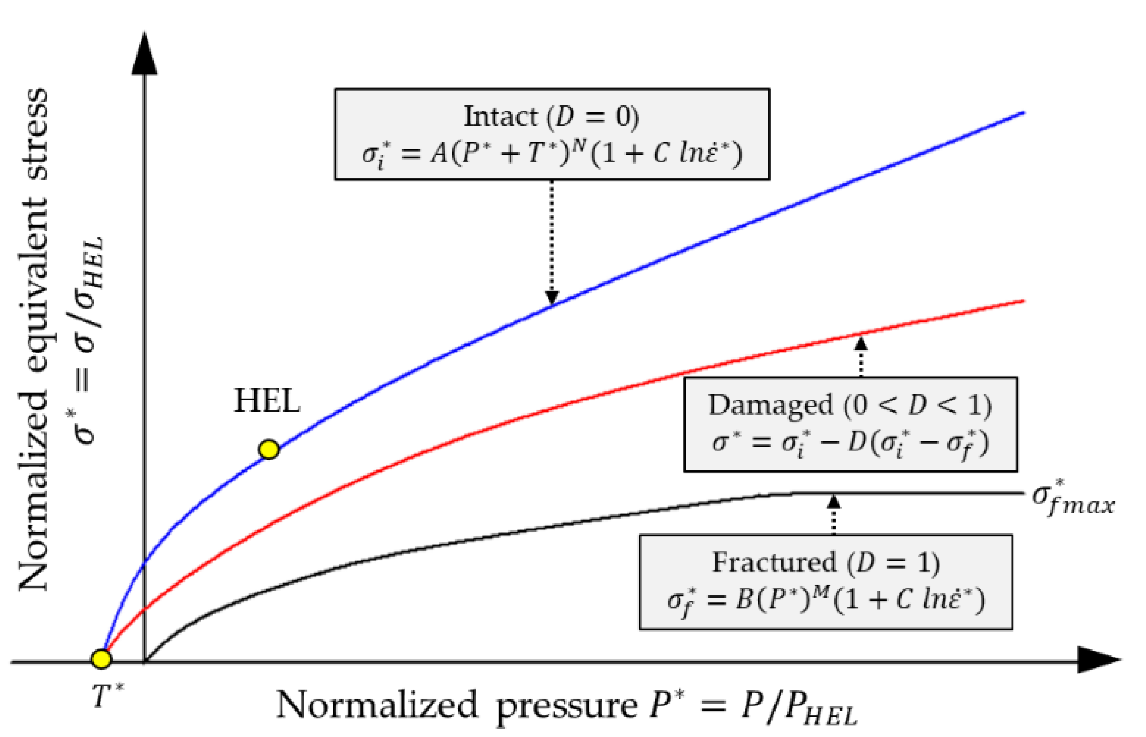
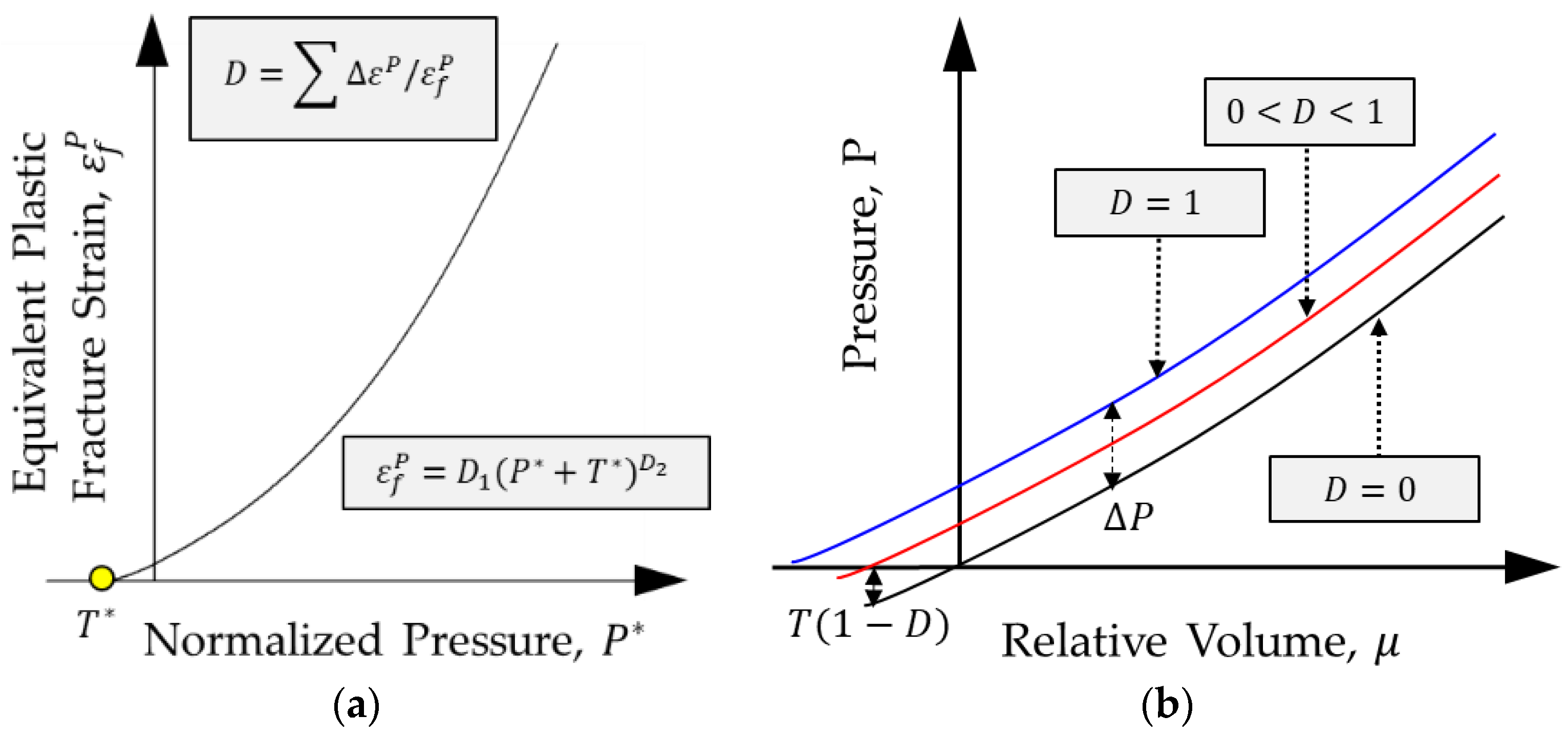
3.2. JH-2 Constitutive Model for Rock Material
3.3. Explosive and Stemming Material Models
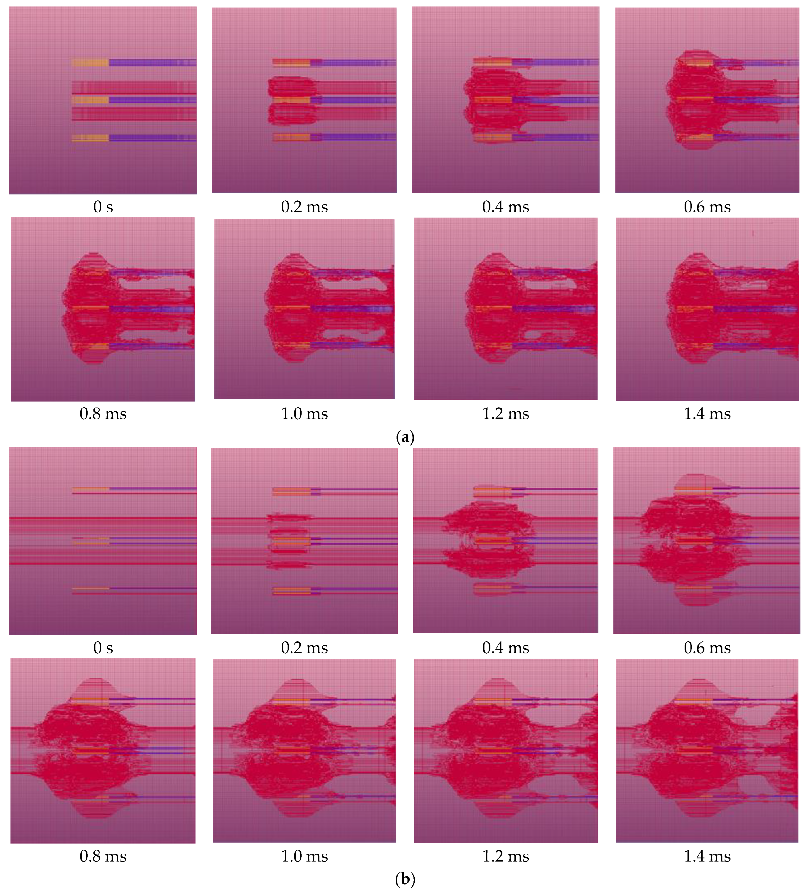
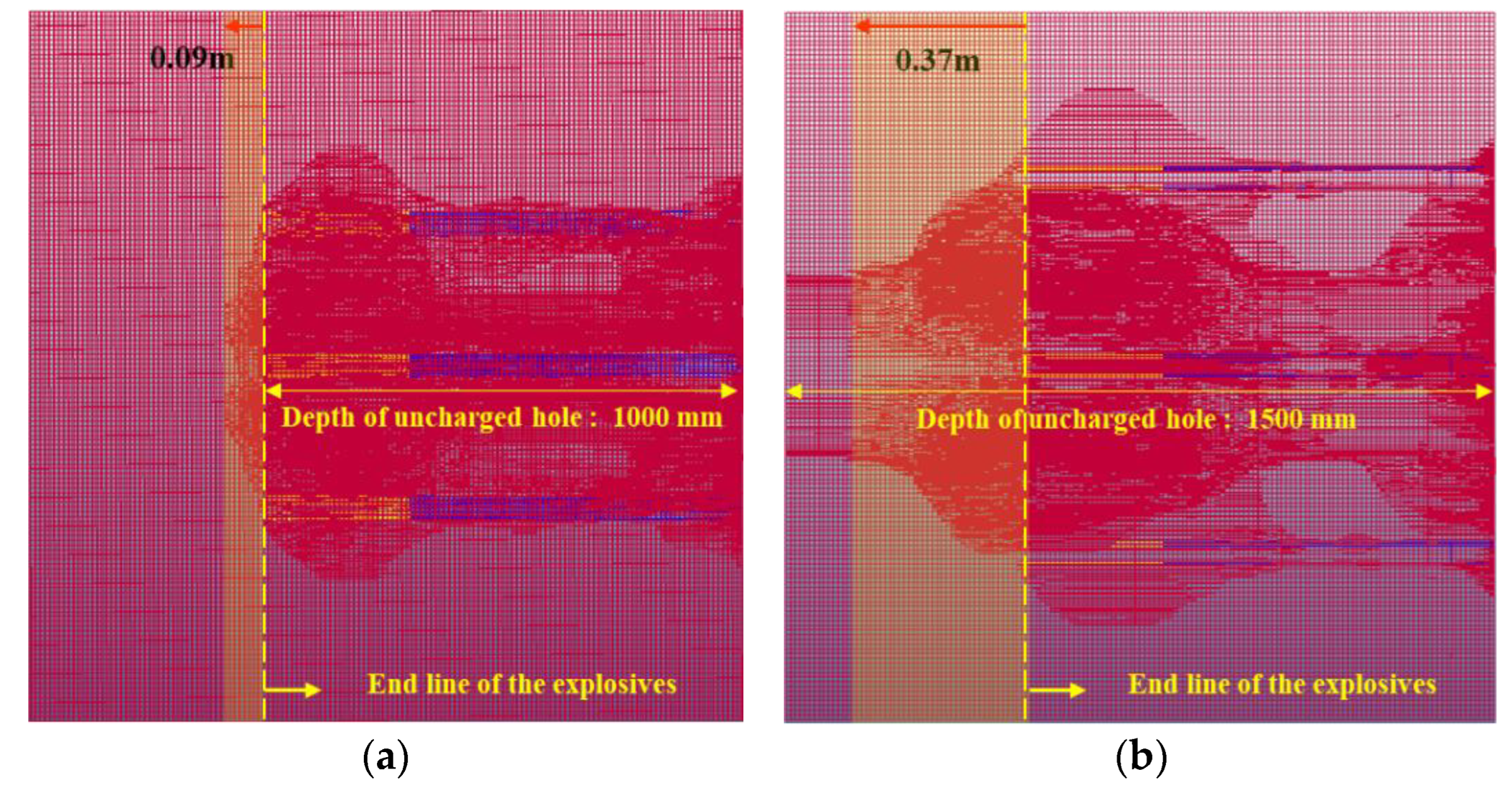
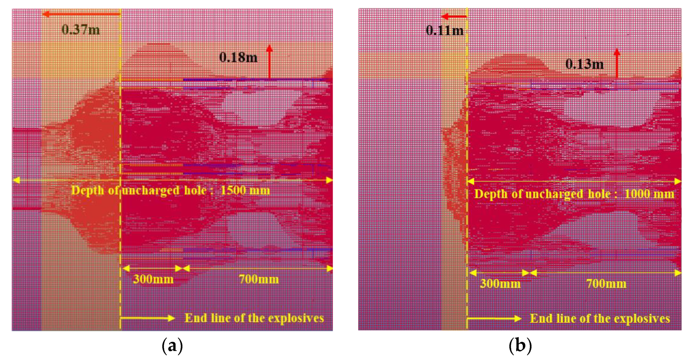
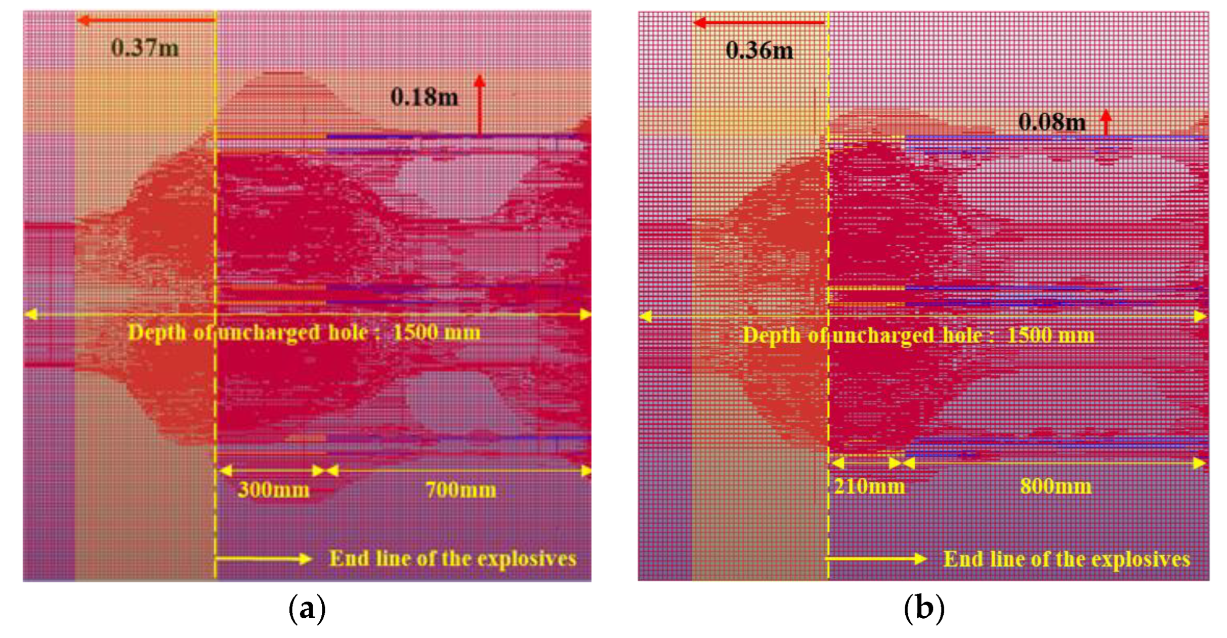
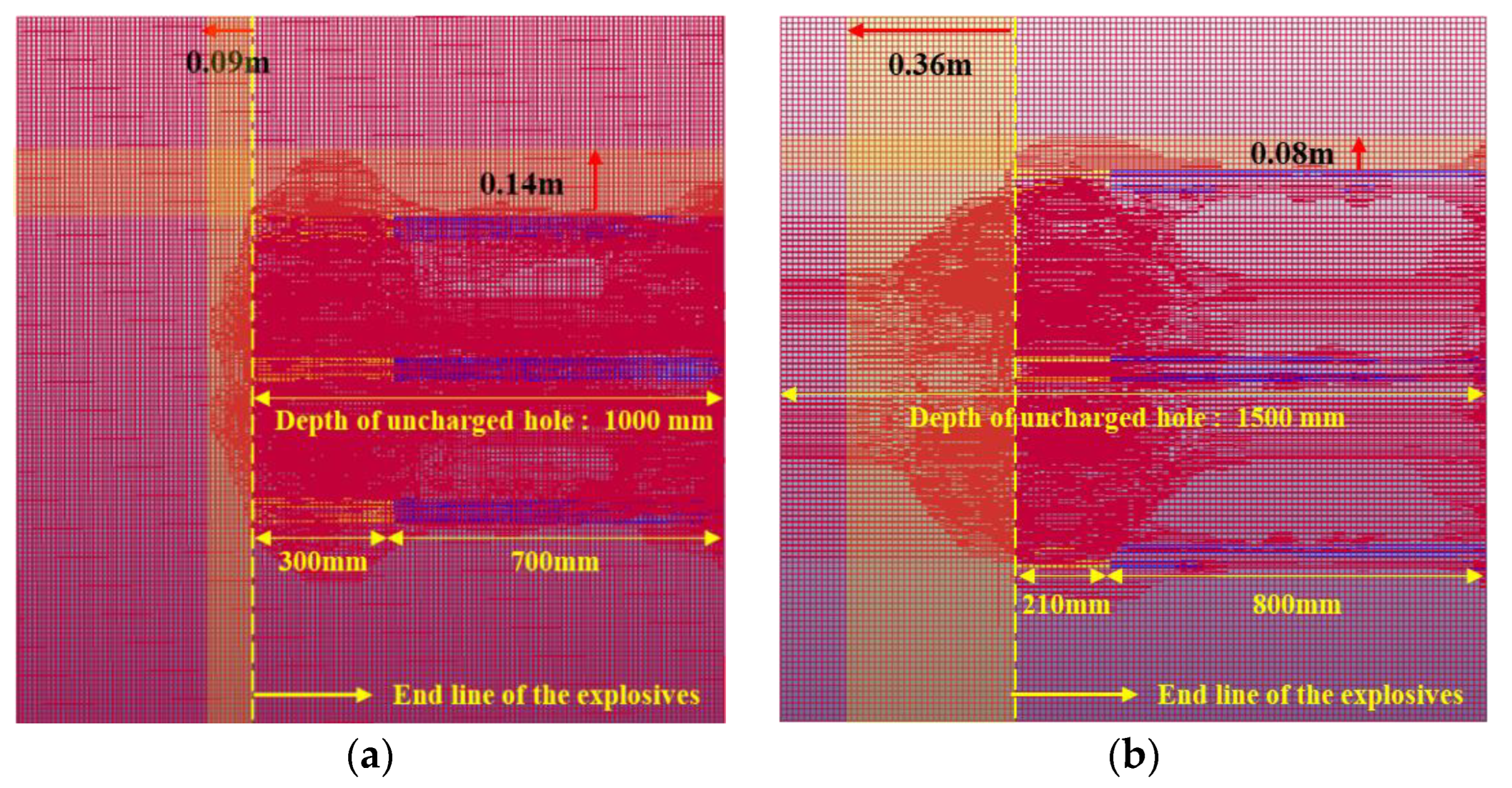
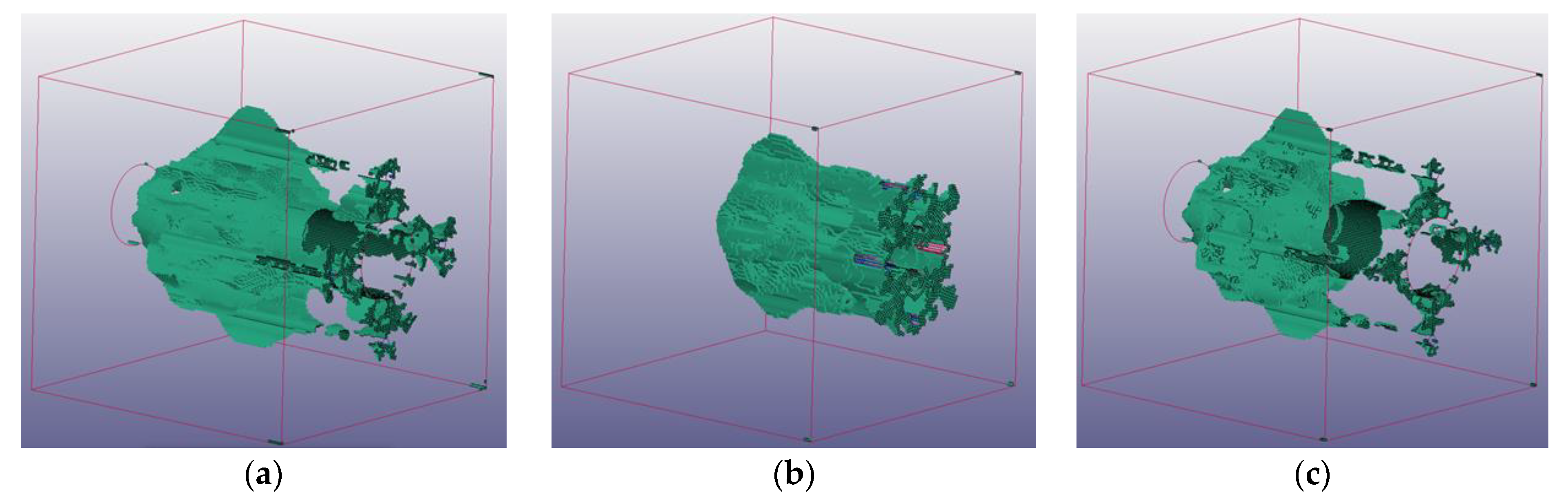
3.4. Results of Numerical Analyses
4. Discussion
4.1. Effect of Increasing the Advance Rate in the Burn-Cut and LLB Methods
4.2. Effect of Increasing the Advance in the Burn-Cut and LLB Methods
4.3. Effect of Reducing the Amount of Explosives
4.4. Comparison of Each Analysis Model using Eroding Elements
5. Conclusions
Author Contributions
Funding
Institutional Review Board Statement
Informed Consent Statement
Data Availability Statement
Conflicts of Interest
References
- New, B.M. Ground vibration caused by construction works. Tunn. Undergr. Space Technol. 1990, 5, 179–190. [Google Scholar] [CrossRef]
- Berta, G. Blasting-induced vibration in tunneling. Tunn. Undergr. Space Technol. 1994, 9, 175–187. [Google Scholar] [CrossRef]
- Singh, P.K.; Vogt, W. Effect of direction of initiation on ground vibrations. Int. J. Min. Reclam. 1998, 12, 75–78. [Google Scholar] [CrossRef]
- Singh, T.N.; Singh, V. An intelligent approach to prediction and control ground vibration in mines. Geotech. Geol. Earthq. Eng. 2005, 23, 249–262. [Google Scholar] [CrossRef]
- Lu, C.P.; Dou, L.M.; Wu, X.R.; Xie, Y.S. Case study of blast-induced shock wave propagation in coal and rock. Int. J. Rock Mech. Min. Sci. 2010, 47, 1046–1054. [Google Scholar] [CrossRef]
- Kuzu, C.; Guclu, E. The problem of human response to blast induced vibrations in tunnel construction and mitigation of vibration effects using cautious blasting in half-face blasting rounds. Tunn. Undergr. Space Technol. 2009, 24, 53–61. [Google Scholar] [CrossRef]
- Ainalis, D.; Kaufmann, O.; Tshibangu, J.P.; Verlinden, O.; Kouroussis, G. Modelling the source of blasting for the numerical simulation of blast-induced ground vibrations: A review. Rock Mech. Rock Eng. 2017, 50, 171–193. [Google Scholar] [CrossRef]
- Mesec, J.; Kovac, I.; Soldo, B. Estimation of particle velocity based on blast event measurements at different rock units. Soil Dyn. Earthq. Eng. 2010, 30, 1004–1009. [Google Scholar] [CrossRef]
- Yan, Y.; Hou, X.M.; Fei, H.L. Review of predicting the blast-induced ground vibrations to reduce impacts on ambient urban communities. J. Clean Prod. 2020, 260, 121135–121155. [Google Scholar] [CrossRef]
- Kim, M.S.; Lee, S.S. The efficiency of large hole boring (MSP) method in the reduction of blast-induced vibration. Appl. Sci. 2021, 11, 1814. [Google Scholar] [CrossRef]
- Beak, J.H.; Beak, S.H.; Han, D.H.; Won, A.R.; Kim, C.S. A study on the design of PLHBM. Explos. Blasting. 2012, 30, 66–76. [Google Scholar]
- Ma, G.W.; An, X.M. Numerical simulation of blasting-induced rock fractures. Int. J. Rock Mech. Min. Sci. 2008, 45, 966–975. [Google Scholar] [CrossRef]
- Qui, X.Y.; Hao, Y.; Shi, X.; Hao, H.; Zhang, S.; Gou, Y. Numerical simulation of stress wave interaction in short-delay blasting with a single free surface. PLoS ONE. 2018, 13, e0204166. [Google Scholar] [CrossRef] [Green Version]
- Jeong, H.Y.; Jeon, B.K.; Choi, S.B.; Jeon, S.W. Fracturing behavior around a blasthole in a brittle material under blasting loading. Int. J. Impact Eng. 2020, 140, 103562–103576. [Google Scholar] [CrossRef]
- Zhang, H.; Li, T.C.; Du, Y.T.; Zhu, Q.W.; Zhang, X.T. Theoretical and numerical investigation of deep-hole cut blasting based on cavity cutting and fragment throwing. Tunn. Undergr. Space Technol. 2021, 111, 103854–103871. [Google Scholar] [CrossRef]
- Yang, Y.Z.; Shao, Z.S.; Mi, J.F.; Xiong, X.F. Effect of adjacent hole on the blast-induced stress concentration in rock blasting. Adv. Civ. Eng. 2018, 3, 5172878. [Google Scholar] [CrossRef] [Green Version]
- Kutter, H.K.; Fairhurst, C. On the fracture process in blasting. Int. J. Rock Mech. Min. Sci. Geomech. Abstr. 1971, 8, 189–202. [Google Scholar] [CrossRef]
- Esen, S.; Onederra, L.; Bilgin, H. Modelling the size of the crushed zone around a blasthole. Int. J. Rock Mech. Min. Sci. 2003, 40, 485–495. [Google Scholar] [CrossRef]
- Hopkinson, B. A method of measuring the pressure produced in the detonation of high, explosives or by the impact of bullets. Philos. Trans. R. Soc. Lond. Ser. A 1913, 89, 411–413. [Google Scholar] [CrossRef]
- Kolsky, H. Stress Waves in Solids, 1st ed.; Courier Corporation: Oxford, UK, 1953. [Google Scholar]
- Chai, S.B.; Li, J.C.; Zhang, Q.B.; Li, H.B.; Li, N.N. Stress wave propagation across a rock mass with two non-parallel joints. Rock Mech. Rock Eng. 2016, 49, 4023–4032. [Google Scholar] [CrossRef]
- Oh, S.W.; Choi, B.H.; Min, G.J.; Jung, Y.B.; Cho, S.H. An experimental study on the dynamic increase factor and strain rate dependency of the tensile strength of rock materials. Explos. Blasting 2021, 39, 10–21. [Google Scholar]
- Cho, S.H.; Ogata, Y.; Kaneko, K. Strain-rate dependency of the dynamic tensile strength of rock. Int. J. Rock Mech. Min. Sci. 2003, 40, 763–777. [Google Scholar] [CrossRef]
- Li, X.H.; Zhu, Z.M.; Wang, M.; Shu, Y.; Deng, S.; Xiao, D.J. Influence of blasting load directions on tunnel stability in fractured rock mass. J. Rock Mech. Geotech. Eng. 2022, 14, 346–365. [Google Scholar] [CrossRef]
- Yang, J.H.; Cai, J.Y.; Yao, C.; Li, P.; Jiang, Q.H.; Zhou, C.B. Comparative study of tunnel blast-induced vibration on tunnel surfaces and inside surrounding rock. Rock Mech. Rock Eng. 2019, 52, 4747–4761. [Google Scholar] [CrossRef]
- Hu, Y.G.; Yang, Z.W.; Huang, S.L.; Lu, W.B.; Zhao, G. A new safety control method of blasting excavation in high rock slope with joints. Rock Mech. Rock Eng. 2020, 53, 3015–3029. [Google Scholar] [CrossRef]
- Yin, Y.; Sun, Q.; Zou, B.P.; Mu, Q.Y. Numerical study on an innovative shaped charge approach of rock blasting and the timing sequence effect in microsecond magnitude. Rock Mech. Rock Eng. 2021, 54, 4523–4542. [Google Scholar] [CrossRef]
- Souli, M.; Bouamoul, A.; Nguyen-Dang, T.V. Ale formulation with explosive mass scaling for blast loading: Experimental and numerical investigation. Comput. Model Eng. Sci. 2012, 86, 469–486. [Google Scholar] [CrossRef]
- Olovsson, L.; Souli, M.; Do, I. LS-DYNA—ALE Capabilities (Arbitrary-Lagrangian-Eulerian) Fluid-Structure Interaction Modeling. Livermore Software Technology Corporation. 2003. Available online: https://ftp.lstc.com/anonymous/outgoing/jday/aletutorial-278p.pdf (accessed on 10 March 2022).
- Johnson, G.R.; Holmquist, T.J. Response of boron carbide subjected to large strains, high strain rates, and high pressures. J. Appl. Phys. 1999, 85, 8060–8073. [Google Scholar] [CrossRef]
- Holmquist, T.J.; Johnson, G.R. Response of silicon carbide to high velocity impact. J. Appl. Phys. 2002, 91, 5858–5866. [Google Scholar] [CrossRef]
- Wang, J.X.; Yin, Y.; Esmaieli, K. Numerical simulations of rock blasting damage based on laboratory-scale experiments. J. Geophys. Eng. 2018, 15, 2399–2417. [Google Scholar] [CrossRef]
- Wang, J.X.; Yin, Y.; Lu, C.W. Johnson–Holmquist-II(JH-2) constitutive model for rock materials: Parameter determination and application in tunnel smooth blasting. Appl. Sci. 2018, 8, 1675. [Google Scholar] [CrossRef] [Green Version]
- Lee, E.L.; Horning, H.C.; Kury, J.W. A Diabatic Expansion of High Explosives Detonation Products; TID4500-UCRL 50422; Lawrence Livermore National Laboratory, University of California: Livermore, CA, USA, 1968.
- Yi, C.P. Improved Blasting Results with Precise Initiation—Numerical Simulation of Sublevel Caving Blasting; Report; Swedish Blasting Research Centre: Stockholm, Sweden, 2013; Volume 3. [Google Scholar]
- Lewis, B.A. Manual for LS-DYNA Soil Material Model 147; Federal Highway Administration: McLean, VA, USA, 2004.
- Koneshwaran, S.; Thambiratnam, D.P.; Gallage, C. Blast response of segmented bored tunnel using coupled SPH-FE method. Structure 2015, 2, 58–71. [Google Scholar] [CrossRef]
- Livermore Software Technology. LS-DYNA Keyword User’s Manual—Volume II R12; Livermore Software Technology: Livermore, CA, USA, 2020. [Google Scholar]
- Baranowski, P.; Mazurkiewicz, L.; Malachowski, J.; Pytlik, M. Experimental testing and numerical simulations of blast-induced fracture of dolomite rock. Meccanica 2020, 55, 2338–2352. [Google Scholar] [CrossRef]
- Cho, S.H.; Kaneko, K. Rock Fragmentation Control in Blasting. Mater. Trans. 2004, 45, 1722–1730. [Google Scholar] [CrossRef] [Green Version]
- Shadabfar, M.; Gokdemir, C.; Zhou, M.L.; Kordestani, H.; Muho, E.V. Estimation of Damage Induced by Single-Hole Rock Blasting: A Review on Analytical, Numerical, and Experimental Solutions. Energies 2020, 14, 29. [Google Scholar] [CrossRef]


| Parameter | Value | Parameter | Value |
|---|---|---|---|
| Density (kg/m3) | 2560 | Maximum normalized fractured strength | 0.160 |
| Shear modulus () | 11.606 | Hugoniot elastic limit () | 4.500 |
| Intact normalized strength parameter A | 1.248 | Pressure component at the Hugoniot elastic limit () | 2.930 |
| Fractured normalized strength parameter B | 0.680 | Fraction of elastic energy loss | 1.000 |
| Strength parameter C | 0.005 | Parameter for a plastic strain to fracture | 0.008 |
| Fractured strength parameter M | 0.830 | Parameter for a plastic strain to fracture | 0.435 |
| Intact strength parameter N | 0.676 | First pressure coefficient K1 () | 10.720 |
| Reference strain rate | 1.000 | Second pressure coefficient K2 () | −386 |
| Maximum tensile strength () | 0.015 | Elastic constant K3 () | 12,800 |
| JWL | Parameter | A () | B () | () | () | |||
| Value | 276 | 8.44 | 5.215 | 2.112 | 0.501 | 3.868 | 1.0 | |
| HEB | Parameter | RO () | D () | () | ||||
| Value | 1180 | 5122 | 9.530 | |||||
| Parameter | Value | Parameter | Value |
| Density () | 2350 | Eccentricity parameter | 0.700 |
| Specific gravity | 2.650 | Moisture content | 6.200 |
| Density of water () | 1000 | Skeleton bulk modulus () | 0.153 |
| Viscoplasticity parameter | 1.100 | Minimum internal friction angle (radians) | 0.063 |
| Viscoplasticity parameter | 0.0 | Volumetric strain at initial damage threshold | 0.001 |
| Maximum number of plasticity iterations | 10.00 | Void formation energy | 10.00 |
| Bulk modulus () | 15.30 | Strain hardening, percent of where non-linear effects start | 10.00 |
| Shear modulus () | 19.50 | Pore water effects on bulk modulus PWD1 | 0.0 |
| Peak shear strength angle (radians) | 0.420 | Pore water effects on effective pressure PWD2 | 0.0 |
| Cohesion () | 0.011 | Strain hardening, amount of non-linear effects | 10.00 |
| 1.29 | 0.0 | 0.0 | 0.0 | 0.0 | 0.4 | 0.4 | 0.0 | 0.25 |
Publisher’s Note: MDPI stays neutral with regard to jurisdictional claims in published maps and institutional affiliations. |
© 2022 by the authors. Licensee MDPI, Basel, Switzerland. This article is an open access article distributed under the terms and conditions of the Creative Commons Attribution (CC BY) license (https://creativecommons.org/licenses/by/4.0/).
Share and Cite
Kim, M.-S.; Kim, C.-Y.; Song, M.-K.; Lee, S.S. Assessment of the Blasting Efficiency of a Long and Large-Diameter Uncharged Hole Boring Method in Tunnel Blasting Using 3D Numerical Analysis. Sustainability 2022, 14, 13347. https://doi.org/10.3390/su142013347
Kim M-S, Kim C-Y, Song M-K, Lee SS. Assessment of the Blasting Efficiency of a Long and Large-Diameter Uncharged Hole Boring Method in Tunnel Blasting Using 3D Numerical Analysis. Sustainability. 2022; 14(20):13347. https://doi.org/10.3390/su142013347
Chicago/Turabian StyleKim, Min-Seong, Chang-Yong Kim, Myung-Kyu Song, and Sean Seungwon Lee. 2022. "Assessment of the Blasting Efficiency of a Long and Large-Diameter Uncharged Hole Boring Method in Tunnel Blasting Using 3D Numerical Analysis" Sustainability 14, no. 20: 13347. https://doi.org/10.3390/su142013347