Article

Analysis and Residual Behavior of Encased Pultruded GFRP I-Beam under Fire Loading

1
Department of Civil Engineering, University of Baghdad, Baghdad 17001, Iraq
2
Department of Engineering and Technology, Texas A&M University-Commerce, Commerce, TX 75429, USA
*
Author to whom correspondence should be addressed.
Sustainability 2022, 14(20), 13337; https://doi.org/10.3390/su142013337
Submission received: 18 September 2022 / Revised: 8 October 2022 / Accepted: 14 October 2022 / Published: 17 October 2022

Abstract

:
In this paper, fire resistance and residual capacity tests were carried out on encased pultruded glass fiber-reinforced polymer (GFRP) I-beams with high-strength concrete beams. The specimens were loaded concurrently under 25% of the ultimate load and fire exposure (an increase in temperature of 700 °C) for 70 min. Subsequently, the fire-damaged specimens were allowed to cool and then were loaded statically until failure to explore the residual behaviors. The effects of using shear connectors and web stiffeners on the residual behavior were investigated. Finite Element (FE) analysis was developed to simulate the encased pultruded GFRP I-beams under the effect of fire loading. The thermal analyses were performed using the general-purpose FE ABAQUS package. This simulation considered the material and geometric nonlinearities and the effect of temperature on the constitutive models of materials. The FE results showed good agreement with the experimental data. The residual peak load and the corresponding mid-span deflection obtained were 5% and 4% higher than those of the experimental results. The validated FE model was utilized to explore the influence of the tensile strength of GFRP and concrete compressive strength on the post-fire flexural behavior of the encased GFRP I-beams. The encased GFRP beams kept higher residual peak loads. Moreover, the encased GFRP beam with shear connectors (EGS-F), encased GFRP beam with web stiffeners (EGW-F), and encased GFRP beam with shear connectors and web stiffeners (EGSW-F) exhibited higher residual peak loads due to the presence of shear connectors and web stiffeners. However, the web stiffeners showed a minor enhancement in the peak load.

1. Introduction

Pultruded glass fiber-reinforced polymer (GFRP) profiles are seeing increasing applications in structural engineering due to their numerous advantages [1,2]. With advances in material science, steel substitutes such as GFRP can now provide enough structural performance for reinforcing concrete at costs that are equivalent to or less than steel [3]. Per ton of production, GFRP emits significantly fewer emissions than steel. GFRP-reinforced beams use approximately half as little energy and emit 43% less carbon dioxide than steel [4]. Therefore, GFRP beams present a feasible and cost-effective solution in which environmental sustainability plays a significant role.
Concerns about the behavior of these materials at elevated temperatures are legitimate. GFRP materials are softened and creeped when temperatures rise to 100 °C and 200 °C, which results in a significant loss of stiffness and strength. When temperatures increase to 300 °C and 500 °C, the organic matrix decomposes, and heat, smoke, and toxic volatiles are released. The low thermal conductivity of fiber-reinforced polymer (FRP) materials delays the spread of fire. However, the nature of FRP’s polymer matrix is an explosive substance [5]. On the other side, fire is the most serious condition a reinforced concrete structure may face during its service life. Therefore, fire resistance must be considered in reinforced concrete design [6]. High-strength concrete is being more widely employed in various civil engineering applications where providing suitable fire safety measures is a major safety need in building design. Concerns about the behavior of high-strength concrete in fire have grown as the use of such concrete increased [7,8]. The encased beam is important to provide protection to GFRP material. Therefore, it is significant to understand the behavior of encased GFRP beams at high temperatures and under exposure to fire loading. The concrete cover, which serves as a heat-resistant insulation material, shields the embedded member from fire [9].
Khaneghahi et al. [10] studied the compressive performance of GFRP profiles with different shapes under the effect of high temperatures (400 °C). The compressive strength of the GFRP profiles was reduced by half as the temperature approached 90 °C. The temperature and the ratio of the cross-sectional area to the external perimeter were the two important parameters affecting the cross-section capacity. When the temperature surpassed 120 °C, the most capacity of the pultruded profiles was lost due to softened resin. Morgado et al. [11] studied experimentally the fire resistance of pultruded GFRP beams exposed to the ISO 834 time–temperature curve. The primary parameters were the number of sides exposed to fire, the load level used, and the use of various fire prevention systems. The three-sided exposure reduced fire resistance significantly compared to the one-sided exposure for unprotected and protected profiles. Moreover, raising the applied load level reduced the fire resistance. The tensile and compressive strength of GFRP decreased by 54% and 5% after exposure to 220 °C [12]. The temperature caused the flexural collapse in reinforced concrete beams due to the fracture of the steel reinforcement [13]. The deflection of the beams was twice as high temperature relative to those under ambient temperature [13], and the ultimate load of beams decreased by 80% at 500 °C. The normal-strength and high-strength concrete beams were compared under fire [14]. The time–temperature relationships in the beam section were similar and did not affect the strength of the concrete. The increasing rates of deflection for normal and high-strength concrete beams were the same before spalling; then, for high-strength concrete beams, the rate became higher than normal-strength concrete after spalling [14]. The stiffness of GFRP and steel-reinforced concrete beams exhibited similar reductions after exposure to 500 °C regardless of load levels [15]. Guo et al. [16] investigated the mechanical behavior of pultruded GFRP tubular filled with short concrete columns subjected to elevated temperatures and axially tested. The ultimate strength and initial stiffness decreased and ductility dramatically increased with rising temperature (200 °C). Dai et al. [17] proposed an enhanced FE approach for fire performance simulation of FRP-strengthened RC beams. In the proposed method, rational and dependable material constitutive laws were used.
The effect of fire on structural elements was explored in several previous studies. However, it is unusual to find fire performance of encased pultruded GFRP beams with high-strength concrete [9]. Therefore, the fire resistance and residual capacity of encased pultruded GFRP I-beams with high-strength concrete beams were tested. The specimens were loaded concurrently under 25% of the ultimate load and fire exposure for 70 min. Subsequently, the fire-damaged specimens were allowed to cool and then were loaded statically until failure to explore the residual behaviors. The effects of using shear connectors and web stiffeners on the residual behavior were investigated. FE analysis was developed to simulate the encased pultruded GFRP I-beams under the effect of fire loading. The validated FE model was utilized to explore the influence of the tensile strength of GFRP and concrete compressive strength on the post-fire flexural behavior of the encased GFRP I-beams.

2. Experimental Program

Five encased pultruded GFRP I-section with high-strength concrete beams were loaded concurrently under 25% of the ultimate load (0.25P) [18] and fire exposure (an increase in temperature of 700 °C) [19] for 70 min. This level of service loading was chosen to avoid any premature failure during the fire loading in the furnace. Subsequently, the fired beams were allowed to cool and then were loaded statically until failure. Table 1 lists the tested specimens and the parameters that were experimentally investigated.
The reference specimen with steel reinforcing is identified in the adopted nomenclature by the symbol Ref. I-beams covered with GFRP are denoted by the symbol EG. Using shear connections and web stiffeners is denoted by the subsequent symbols S and W. Exposure to fire is denoted by the final symbol F.

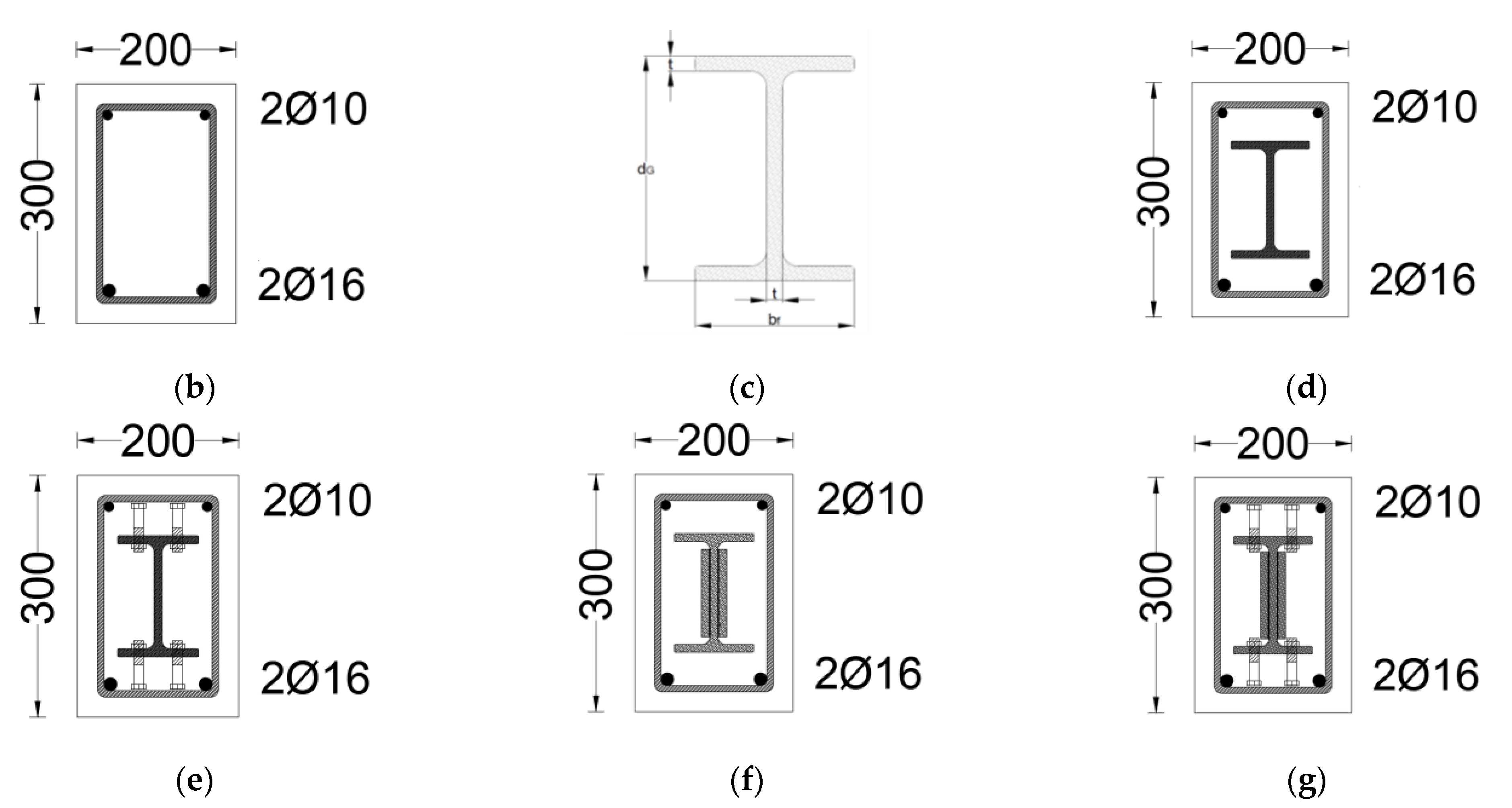
2.1. Details of the Specimens

High-strength concrete cross-sections of 300 mm in height and 200 mm in width were reinforced with two steel rebars of Ø16 mm in the tension zone and two steel rebars of Ø10 mm in the compression zone, as shown in Figure 1a. The reference specimen Ref-F was used as a reference beam with conventional reinforcement without the GFRP beam, as shown in Figure 1b. In contrast, the other specimens EG-F, EGS-F, EGW-F, and EGSW-F were reinforced with embedded pultruded GFRP I-beams with a length of 2900 mm, a depth of 150 mm (dG), a flange width of 100 mm (bf), and flange and web thicknesses of 10 mm (t), as shown in Figure 1. All specimens were reinforced with transverse reinforcement of Ø10 mm stirrups at 125 mm longitudinal spacing. The overall and effective lengths of the specimens were 3000 mm and 2750 mm (see Figure 1).
Steel bolts with a length of 60 mm and a diameter of 12 mm were used as shear connectors to increase the composite interaction between the embedded GFRP I-beam and concrete in specimens EGS-F and EGSW-F. The shear connectors were arranged in two rows at 375 mm longitudinal spacing on the top and bottom flanges of the GFRP I-beams, as illustrated in Figure 1e. For specimen EGSW-F, 110 mm × 25 mm rectangular GFRP web stiffeners were used to stiffen the web of the GFRP beam to prevent undesired web shear failure. The web stiffeners were placed at a longitudinal spacing of 160 mm on both sides, as shown in Figure 1f,g.

2.2. Mechanical Properties of Material

The mixing proportion of the high-strength concrete adopted in this experimental work is listed in Table 2. Typical Portland cement, gravel as a coarse aggregate with a size range of 5 to 12 mm, dried sand as a fine aggregate with a size range of 0.075 to 4.75 mm and fineness modulus of 2.9, ordinary tap water, and admixture were used to prepare the concrete mix. According to ASTM C39-39M-21 [20] and ASTM C469-469M-22 [21], three concrete cylinders with dimensions of 150 mm in diameter and 300 mm in height were cast and allowed to cure before being tested for concrete’s compressive strength and elastic modulus at the 28-day age. The compressive strength and elastic modulus were 53.8 MPa and 31,000 MPa.
The steel reinforcement underwent tensile tests. The yield and ultimate stresses of steel rebars with diameters of 10 and 16 mm were measured, and the results are shown in Table 3. According to ASTM A615/A615M-22, at the Consulting Engineering Bureau, College of Engineering, University of Baghdad, three rebars of each diameter were evaluated [22]. The polyester matrix that made up the GFRP pultruded I-beams was strengthened with E-glass fibers. Table 3 provides a list of the mechanical characteristics of the pultruded GFRP I-beam. As per ASTM D695-15 [23] and EN ISO 527-4-21 [24], compression and tension tests were used to acquire these parameters.

2.3. Fire Test Setup and Procedure

The elevated temperature was conducted using a gas furnace with 12 m × 4 m × 3 m, as shown in Figure 2a. The inside of the furnace was covered with a 250 mm insulation layer thickness. At the same time, the floor was made of thermal insulation bricks, which were suitable for joining cement to provide adequate insulation to the temperature inside the furnace. Thirty burners were distributed inside the furnace to uniformly distribute the temperature. Six thermocouples were placed throughout the chamber to monitor the furnace temperature in order to maintain a constant temperature along the beam span during the fire test. As seen in Figure 2b,c, the temperature control cabinet was used to regulate the furnace’s temperature during the fire test. Each specimen was exposed to 700 °C for 70 min and then left to cool to room temperature (32 °C). These levels of loading were selected to avoid any premature failure during the fire loading in the furnace and make sure the test specimen was able to sustain the applied fire loading [19]. The intention of this test was to cause partial damage in the tested specimens due to fire loading to evaluate the residual behaviors.
The change in temperature during the fire test was divided into three stages, as shown in Figure 3 (a) heating to 700 °C (10 min), (b) constant temperature at 700 °C (70 min), and (c) cooling to ambient temperature (220 min). During the heating stage, the furnace was heated according to the ASTM E119-20 [25], as shown in Figure 3. After the furnace reached the predetermined temperature, the specimen was left in the furnace for 70 min at a constant temperature (700 °C). Finally, the specimens were left to cool, as shown in Figure 3.
During the fire loading, a constant load was applied at the mid-span of each specimen before and during heating and continuous until cooling. This load was employed to obtain the service load, which was 25% of the ultimate static load [18]. The load was applied by using a steel block, as shown in Figure 2a. The deflections of specimens were measured at the mid-spans during the fire loading by using the Total Station device, which was directed to the mid-side of each specimen through a glass window in the furnace.

2.4. Residual Strength Test Setup and Procedure

The residual behavior of the fired specimens was investigated by conducting flexural tests after the beams were returned to the ambient temperature. These tests were carried out under three-point loading using a hydraulic jack with an ultimate capacity of 5000 kN. The loading rate was 2.5 kN/min. Linear variable differential transforms (LVDTs) were used to measure deflections at mid-span. Electrical strain gauges were attached to the extreme fiber of the concrete cross-section at mid-span to measure the compressive strains in concrete, as shown in Figure 4. The strains and deflections were continuously recorded as the applied load increased. Moreover, careful observations of the beams’ failure modes and crack progressions were recorded.

3. Experimental Results

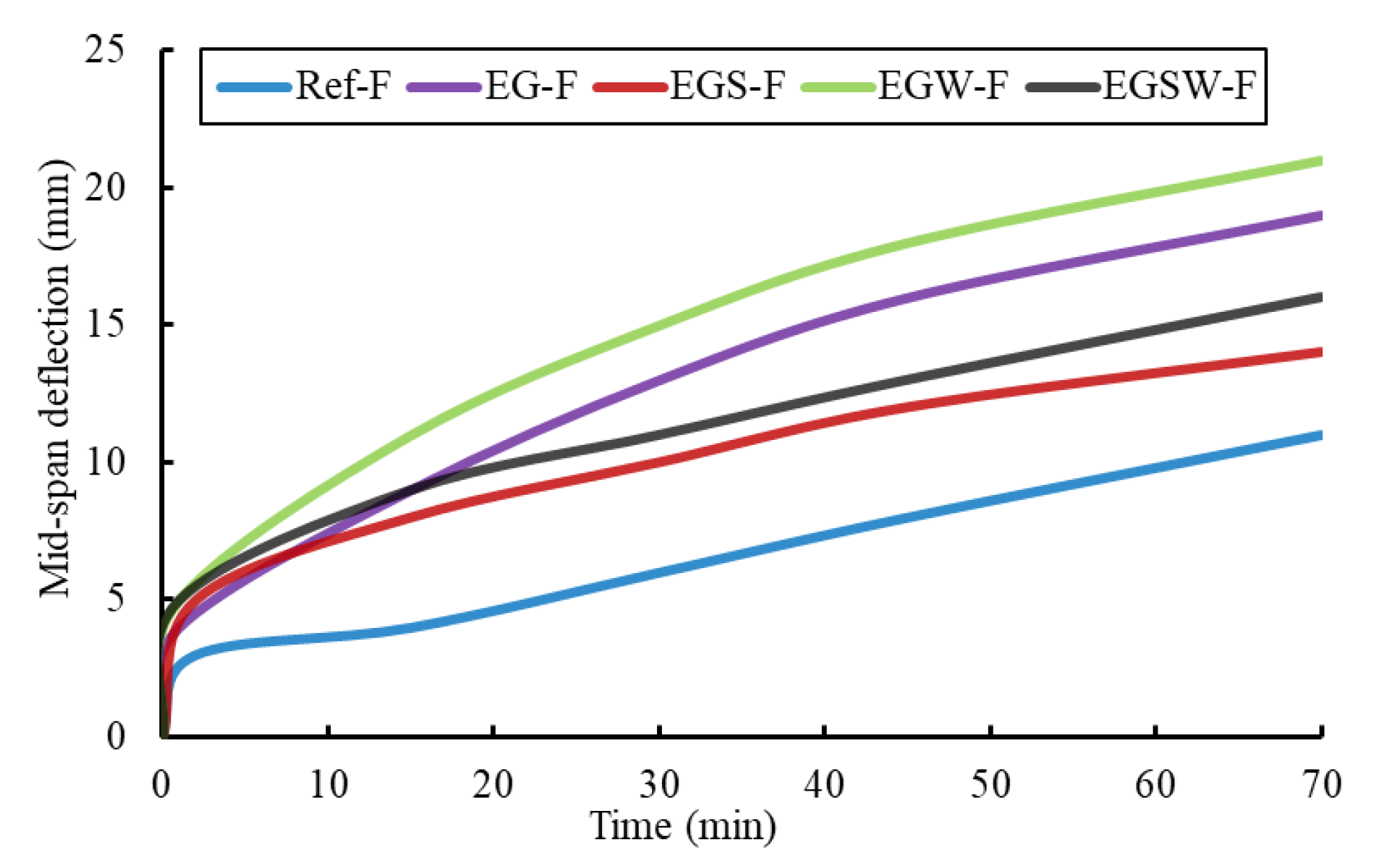
3.1. Fire Test Results

The static ultimate capacities of the tested specimens were obtained previously in [26] to determine the beam service load (25% of the ultimate static capacity) [18,27]. The service load was constant and applied at the mid-span of each specimen when starting the fire exposure. The load was left on the beam until the temperature decreased (during the cooling phase). The initial displacements were recorded at the time of the applied load before the fire loading and they were minimal, as listed in Table 4.
The deformations of the tested specimens during the fire loading were assessed by plotting the measured mid-span deflection versus the fire exposure duration as shown in Figure 5. The specimens exhibited similar behavior and initial mid-span deflection progression of the fire loading during the early stage. As the fire exposure duration increased, the temperature of each specimen increased, and the mid-span deflections gradually increased. The influences of the applied load and different configurations of each specimen caused changes in the behavior during the fire loading due to the degradation in the mechanical properties of materials. The effects of adding the pultruded GFRP I-beams, shear connectors, and web stiffeners on the thermal response of the encased specimens EG-F, EGS-F, EGW-F, and EGSW-F were evident in the comparisons of the deflections as a function of the heating time. The encased specimens exhibited higher levels of final displacements at the end of the fire loading. This could be attributed to the heavier applied load and the more degradations in the pultruded GFRP beams. The mid-span deflections of the encased specimen EG-F, EGS-F, EGW-F, and EGSW-F were 72.7%, 27.2%, 90.9%, and 45.5% greater than the measured value for the reference specimen Ref-F, respectively.
The stiffness (Ks) of each specimen during the fire loading is illustrated in Figure 6. These values were calculated from the experimental data as the applied load per unit deflection [28], which was obtained by dividing the applied load by the corresponding deflection during the fire loading. The reduction rate of the stiffness degradation was high at the first stage of heating, and then it became steady after 20 min. The mechanical properties of the GFRP were affected in terms of stiffness loss and strength degradation of the resin at high temperatures. After this time, the reduction rate in stiffness was slight and approximately constant for all specimens. The stiffness of specimens EG-F and EGW-F was identical during the fire loading. The encased specimen EGSW-F showed the highest stiffness relative to the other encased specimens due to the existence of shear connectors as well as web stiffeners. No severe damage or fragmentation was observed on the specimens’ surfaces. Only thermal cracks appeared during the fire loading, as shown in Figure 7.

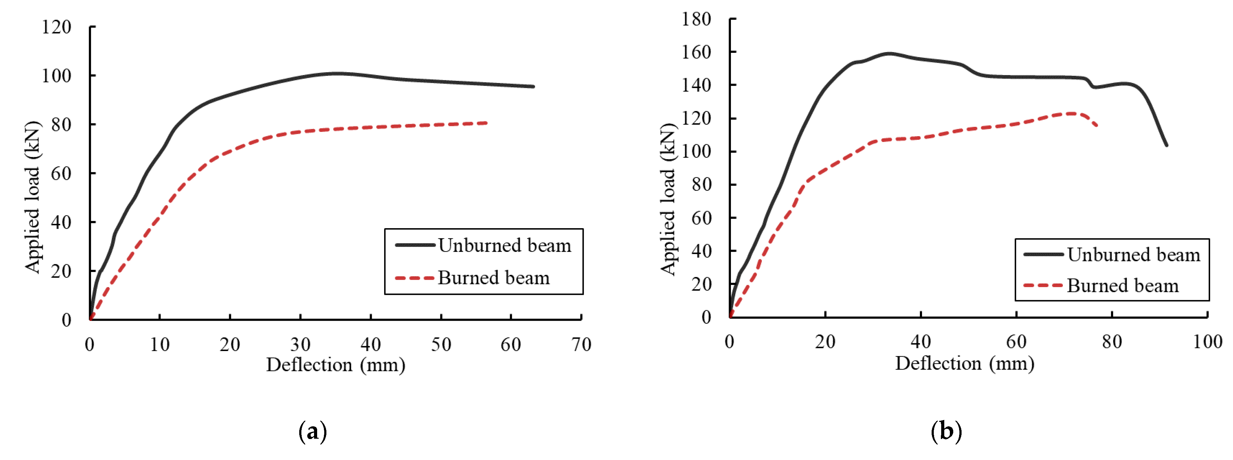
3.2. Strength and Residual Response

The residual capacities of the fire-damaged specimens were investigated statically by applying incremental loads until failure. In these tests, the deformation responses, compressive strains in concrete, cracking progressions, and failure modes were explored. Figure 8 shows the residual load–deflection relationships for the fire-damaged tested specimens. The peak loads of specimens Ref-F, EG-F, EGS-F, EGW-F, and EGSW-F were 80.6 kN, 122.1 kN, 149.6 kN, 130.1 kN, and 166.2 kN, respectively. The flexural response of the fire-damaged specimens including the yielding loads, peak loads, and corresponding displacements are summarized in Table 5. In the load–deflection relationship, the tested specimens have two distinct phases: (1) linear response until yielding in the steel reinforcement and (2) curvilinear response until failure. Yielding occurred at loading levels of 60 kN, 84 kN, 93 kN, 95 kN, and 107 kN for specimens Ref-F, EG-F, EGS-F, EGW-F, and EGSW-F, respectively. There were significant increases in the yielding loads by 40%, 55%, 58%, and 79% relative to the reference specimen, respectively. In the first phase, cracking and temperature-induced deterioration in the beam after fire exposure were obtained. In the second one, yielding in the steel reinforcement and fracture of the GFRP beams occurred. The flexural stiffness degraded when the second phase started.
The load–compressive strains in concrete relationships are shown in Figure 9. The reference specimen Ref-F exhibited the minimal compressive strain of 0.0029 με. However, the strain measurements for the encased specimens EG-F, EGS-F, EGW-F, and EGSW-F were 0.0032, 0.004, 0.0033, and 0.0033 με, respectively. The embedded GFRP beams improved the residual capacity and stiffness of the fire-damaged specimens. Moreover, the strain levels in specimens EGS-F and EGSW-F were relatively higher than those in the other specimens due to the presence of shear connectors.
Static tests were performed on the unburned specimens of this paper in [6,26]. To highlight the residual strength and deformation of the burned specimens, Figure 10 presents comparisons between the burned specimen and its peer unburned one. Moreover, comparisons of peak loads and the corresponding deflection measurements are summarized in Table 6 for the burned and unburned specimens. It was deduced that the encased GFRP beams could significantly reduce the residual behavior of the fire-damaged specimens relative to the reference one. The bond between steel reinforcement and concrete and the bond between GFRP beams and concrete played significant roles in controlling the structural behavior of the encased specimens [29,30]. The exposure to fire decreased the bond strength between the GFRP beam and concrete [31,32], which caused concrete cover splitting and additional cracks (see Figure 11), especially when adding a shear connector.

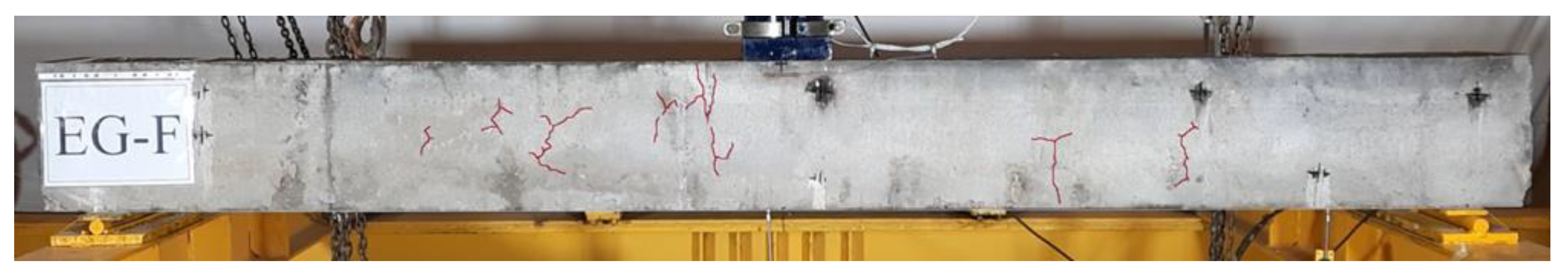
3.3. Crack Patterns and Failure Modes

Pre-existing cracks (thermal cracks) were formed in the fire-damaged specimens due to the elevated temperature, as shown in Figure 12. This was the reason why the specimens did not have clear first cracking loads. The crack patterns and modes of failure after the residual flexural tests are shown in Figure 10. Flexural cracks appeared and propagated in the bending zone. In the cases of encased specimens, limited flexural shear cracks appeared throughout the two shear spans. As the applied load increased, cracks in the flexural zone became wider. The mode of failure of the reference specimen Ref-F was yielding in the steel reinforcement followed by a rupture in these rebars without crushing in concrete. This failure was sudden and divided the reference beam into two parts. On the other hand, the mode of failure of the encased specimens was yielding in the steel reinforcement followed by a rupture in the embedded GFRP I-beam and steel rebars. This failure was accompanied by a sound, and then, the concrete was crushed in compression. However, the encased specimens were not divided into two parts as the reference specimen because the embedded GFRP I-beams were intact and working on the compression side.

4. Numerical Modeling

FE analysis was developed to simulate encased pultruded GFRP I-beams under the effect of fire loading. The thermal analyses were performed using the general-purpose FE ABAQUS package [33].

4.1. Element Selection

Six parts (concrete, steel reinforcement, stirrups, pultruded GFRP I-beam, shear connectors, web stiffeners, and steel plates) were modeled and assembled together, as shown in Figure 13. Two independent analysis stages were adopted in this study to consider the fire loading and residual static tests. Therefore, thermal-displacement coupled and static analyses were used. Subsequently, two different element types were utilized in this study for each part. For the thermal-displacement coupled analysis, the eight-node thermally coupled brick trilinear displacement element, C3D8T, was used to model concrete, steel plates, and shear connectors. A two-node three-dimensional coupled temperature-displacement truss element, T3D2T, was used to model the steel reinforcement. In contrast, the four-node general-purpose shell, finite membrane strains, and bilinear temperature in the shell surface element, S4T, was used to model the GFRP I-beams. On the other hand, a continuum eight-node solid elements reduced integration element, C3D8R, was employed to simulate the nonlinearity and complexity of concrete in static analysis. The same element was utilized to simulate shear connectors and steel plates. The embedded shell element four-node doubly curve with reduced integration element, S4R, was used for the pultruded GFRP I-beams and web stiffeners. The embedded two-node linear truss element, T3D2, was utilized to model the longitudinal steel rebars and stirrups.

4.2. Mesh Sensitivity Study

The FE mesh plays an important role in the FE analysis. Therefore, increasing the number of elements could increase the precision of the analysis while solving the equation would take a longer time. Several nonlinear analyses were carried out with various element sizes to choose the optimum density of the FE mesh. The investigated mesh sizes were 30 mm, 25 mm and 20 mm. Figure 14 shows comparisons between these selections in terms of the load–deflection relationships relative to the experimental results. The ultimate load and displacement were not adequately predicted by the coarse meshes (30 mm), whereas the fine meshes 20 mm and 25 mm gave accurate prediction for both ultimate load and displacement. Since there was no significant difference between the 20 mm and 25 mm sizes, the 25 mm mesh size was utilized through the numerical analysis of this study in order to obtain the needed precision within an acceptable amount of time.

4.3. Boundary Conditions and Applied Load

The beams were analyzed as simply supported beams with hinge support on one side and roller support on the other side. The vertical displacement was avoided to represent the roller support (Y-direction), whereas the Z and Y directions were restricted for the hinge support. Bearing steel plates were used in the FE model to avoid stress concentrations at the supports and loading points. The bearing plate–concrete interface was represented as a surface-to-surface interaction. Moreover, surface-to-surface contact pairs were used to represent the bond between the concrete and GFRP I-beams. The steel reinforcement had a tie constrain with concrete, while shear connectors and web stiffeners were depicted as embedded in concrete. The boundary conditions of the fire surface were subjected to convective and radiated conditions. The fire surface’s film coefficient was 25 W/(m2 °C), and the emissivity of surface radiation was 0.7 according to EN 1992 1.2 [34]. The FE analysis employed the displacement-controlled technique by determining the vertical displacement value of the reference points.

4.4. Material Modeling

The thermal parameters of concrete, steel, and GFRP in the temperature field analysis mainly include thermal conductivity and specific heat and density. The thermal properties of high-strength concrete and normal-strength concrete are very similar [35]. The thermal conductivity, specific heat capacity, and concrete density were based on EN 1992 1.2 [34].

4.4.1. Concrete Material Modeling

When subjected to elevated temperatures, concrete experiences significant changes in its mechanical properties, including loss of strength and stiffness [26]. The constitutive model of concrete under the effect of elevated temperature was adopted in this analysis based on the concrete damage plasticity (CDP) model in ABAQUS [33]. Isotropic principles were adopted in this model. Combining compressive and tensile plasticity with scalar damage was a term used to describe the irreversible loss of stiffness that occurs throughout fracturing. The constitutive model was defined by elastic and inelastic characteristics that were temperature dependent, and the coefficient of thermal expansion of concrete was defined. The elastic modulus and Poisson’s ratio were the two most significant variables to define the elastic mechanical behavior of concrete. The equation below was used to model the compressive behavior of concrete under elevated temperature [34]:
f c , T = 3 ε f c , 20 ε c 1 T ( 2 + ( ε ε c 1 T ) 3               ε   ε c 1 T        
where f c , T and f c , 20 were the compressive strength of concrete at temperatures T and 20 °C, respectively. Ε was the corresponding strain, and ε c 1 T is the concrete strain corresponding to the ultimate compressive strength f c at temperature T.
At elevated temperatures, the tensile strength of concrete changed according to EN 1992 1.2 [34], which was modified by Dwaikat and Kodur [36] to prevent the state that the tensile strength of concrete becomes zero at relative temperatures (600 °C). The varying tensile strength of concrete with temperature was defined by the following expressions [36]:
f t , T = f t , 20                     f o r   T 100  
f t , T = f t , 20 × ( 600 T ) 500       f o r   100 T 550  
f t , T = f t , 20 × ( 1200 T ) 6500       f o r   550 T 1200  
where f t , T   and   f t , 20 were the tensile strength of concrete at temperatures T and 20 °C, respectively.

4.4.2. Steel Reinforcement Material Modeling

Neves et al. [37] and Kodur and Agrawal [38] investigated the mechanical performance of steel reinforcement under the effect of fire. The normalized steel reinforcement strength ( f y , T / f y , 20 ) versus temperature is illustrated in Figure 15. The isotropic coefficient of the thermal expansion of steel was taken as 11.7 × 10⁻⁶/°C [39].

4.4.3. GFRP Material Modeling

The softening of the polymer matrix caused GFRP’s mechanical characteristics to deteriorate at high temperatures rapidly. The strength of GFRP at 300 °C decreased to 50% of its strength at ambient temperature [40]. The temperature of reducing strength to 50% of its initial value was called critical temperature. At this temperature, the polymer matrix in FRP decomposed, but GFRP stayed effective. The temperature-dependent thermal and mechanical property relationship of the GFRP beams is described by the following equations:
σ c = ε E f , T                                           f o r   0 ε   ε f u , T        
ε f u , T = f f , T E f , T
f f . T = f 20 ° C ( 1 a σ 2   tanh ( b σ ( T c σ ) + 1 + a σ 2 )           for   20   T 400  
f f , T = f 20 ° C ( 0.25 + 0.25 600   ( T 400 ) )                 for   400   T 1000  
E f , T = E 20 ° C ( 1 a E 2   tanh ( b E ( T c E ) + 1 + a E 2 )
where a σ = 0.1 , b σ = 0.0081 ,   c σ = 289.14 , a E = 0.0.05 , b E = 0.00791 ,   c E = 320.35 .
Pultruded GFRP material is anisotropic and has coefficients of thermal expansion in the longitudinal and transverse directions, which are dependent on the resin volume fraction. The coefficient of thermal expansion of GFRP was 13 × 10−6/°C (Dura composites, United King).

4.5. Validation of the FE Results

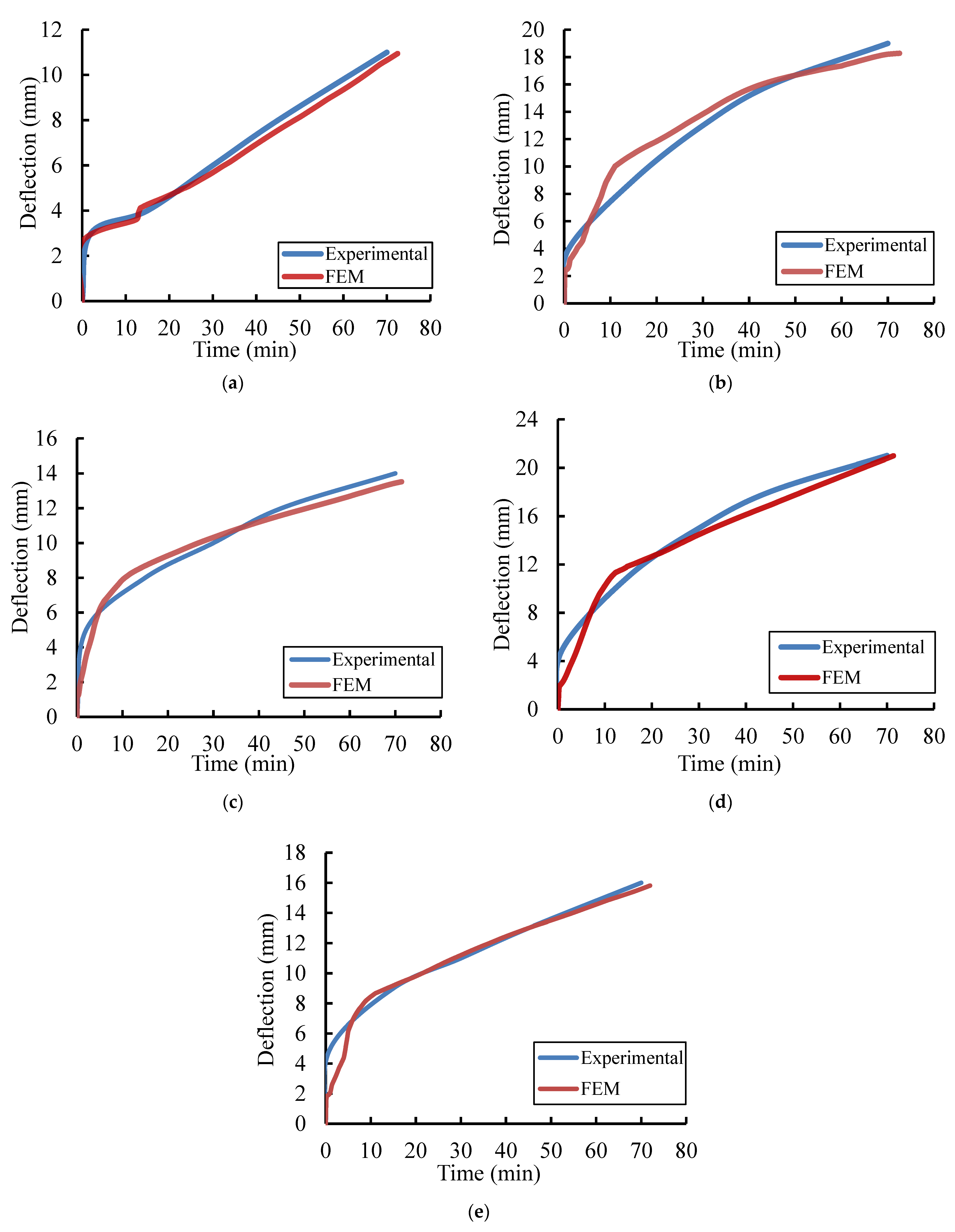
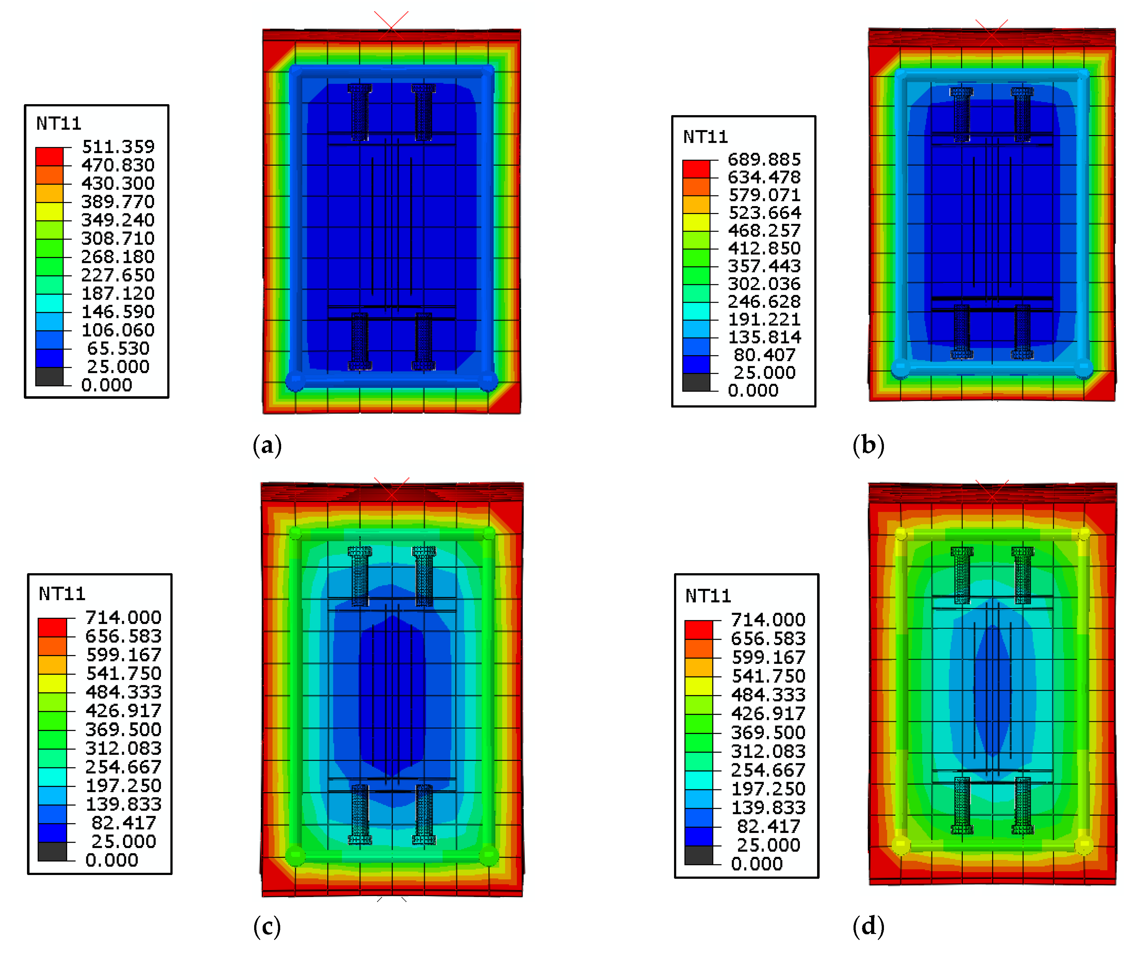
4.5.1. Temperature Field Analysis Results

The deformations of the analyzed beams during the fire loading were verified by comparing the mid-span deflections as a function of the fire exposure duration with the experimental results, as shown in Figure 16. The beams exhibited similar behavior and initial mid-span deflection progression of the fire loading during the early stage with a slight difference. As the fire exposure duration increased, the temperature of each beam increased, and the mid-span deflections gradually increased in good agreement with the experimental results. The proposed model was able to capture the influences of the fire loading with the different configurations of each beam such as shear connectors and stiffness.

4.5.2. Temperature Distribution

The verified FE model was used to explore the temperature distribution through the cross-section over time. The temperature fields were measured after 5 min., 10 min., 30 min., and 70 min for specimen EGSW-F. The transference of the temperature inside concrete was carried out according to ASTM E119-20 [25], as shown in Figure 17.

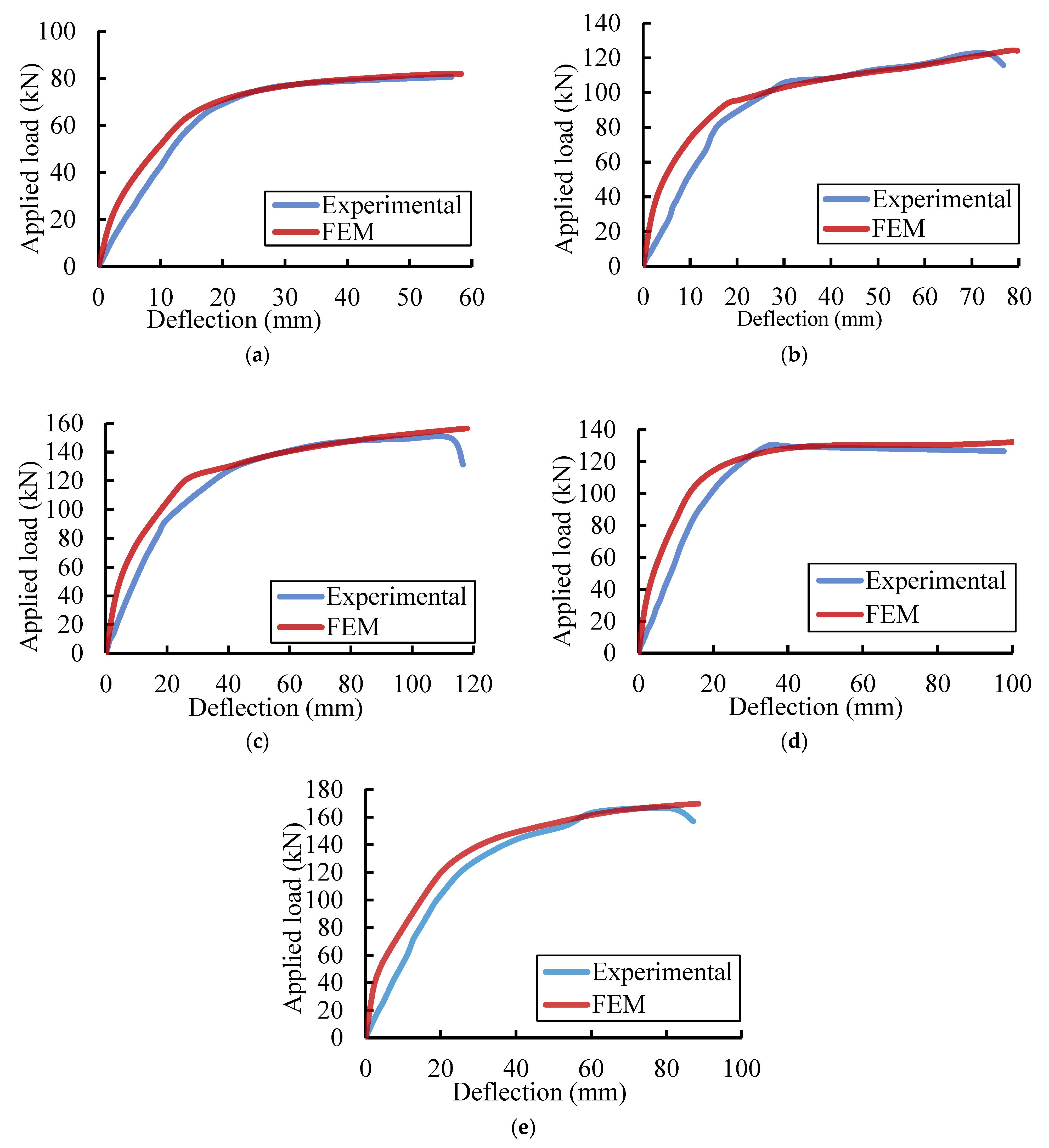
4.5.3. Residual Static Results

Figure 18 shows comparisons between the residual load–deflection relationships for the FE and experimental results. Comparisons between the peak loads and the corresponding deflection are listed in Table 7. The difference in the peak loads reached 4.52%, and the difference in the measured deflections was about 4.08%. Based on the comparisons in Figure 15, the FE results exhibited stiffer behavior relative to the experimental results. These differences in behavior could be attributed to the contact surface simulations, boundary conditions, and constitutive models of materials at elevated temperatures. However, the proposed FE model showed good agreement with the tested specimens. Consequently, comparative parametric research was evaluated using the proposed model.

5. Parametric Study

The post-fire behavior of the encased GFRP beams is significantly influenced by the mechanical characteristics of the concrete and GFRP that remain after fire loading. Therefore, using a validated FE model, the effect of concrete compressive strength and GFRP tensile strength on the post-fire flexural behavior of encased GFRP I-beams was investigated.

5.1. Influence of the Concrete Compressive Strength

This study considered three values of the concrete compressive strength (45 MPa, 53.8 MPa, and 65 MPa) to evaluate its effect after fire exposure. The constitutive model of concrete compressive strength was defined in ABAQUS using the coupled thermo-mechanical analysis. The variations in the residual post-fire behavior as a function of the concrete compressive strength are illustrated in Figure 19 and Figure 20 and listed in Table 8. According to the findings, the residual peak loads for concrete with compressive strengths of 53.8 MPa and 65 MPa, respectively, improved by 6–13% and 12–25% when compared to concrete with a compressive strength of 45 MPa. When the compressive strength was 53.8 MPa or 65 MPa, the mid-span deflections rose by 3–14% and 12–19%, respectively. Furthermore, as the concrete compressive strength rose in comparison to the enclosed beams, the residual peak load and the accompanying mid-span deflection of specimen Ref-F grew at a slower pace. Therefore, the encased GFRP beams kept higher residual peak loads. Moreover, the beams EGS-F, EGW-F, and EGSW-F exhibited higher residual peak loads than beam EG-F due to the presence of shear connectors and web stiffeners. However, the web stiffeners showed minor enhancement in the peak load.

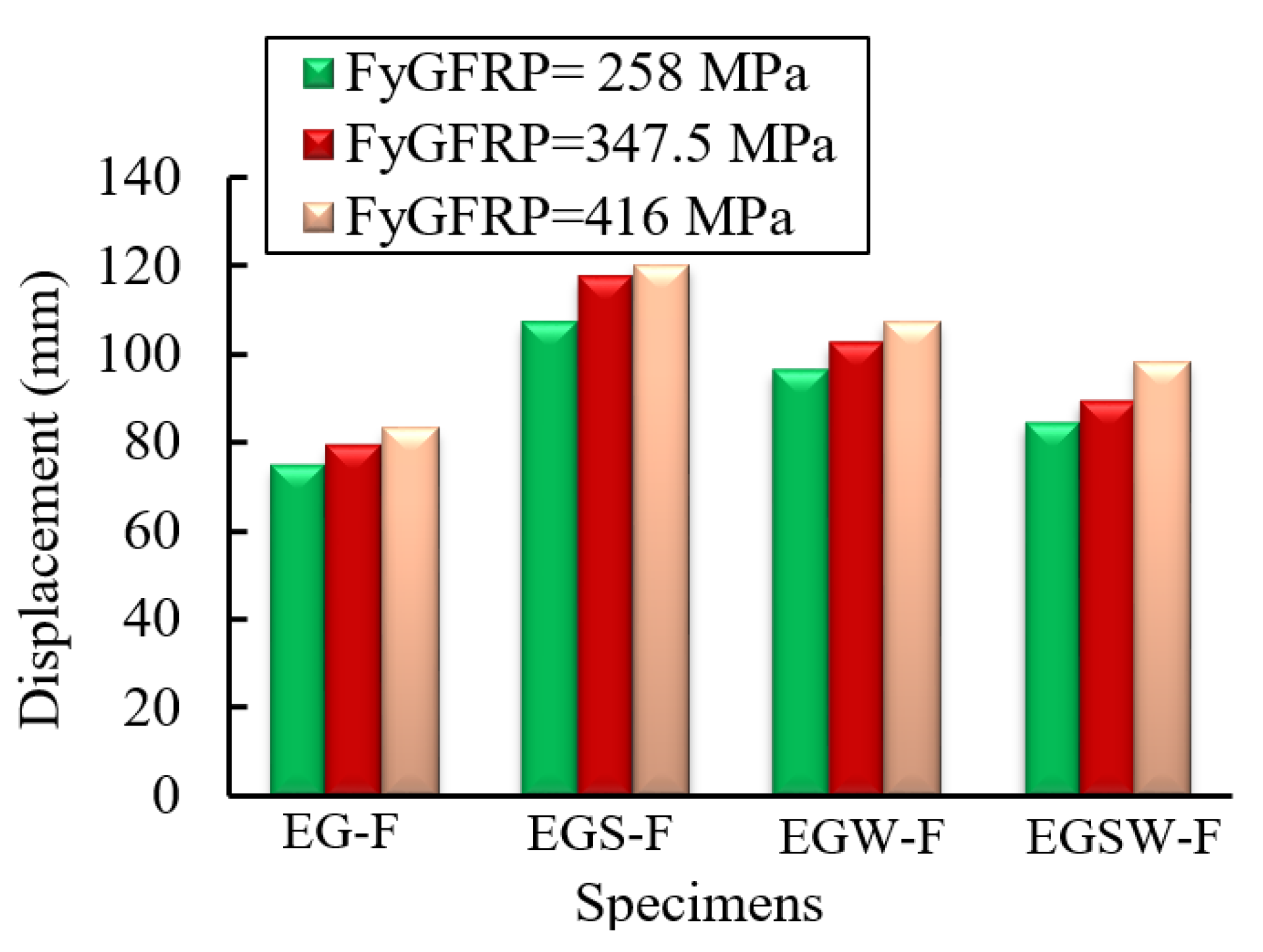
5.2. Influence of the Tensile Strength of the GFRP Beams

The deterioration of the GFRP mechanical properties due to fire loading reduced the structural capacity of the encased GFRP beams [40]. The influence of the tensile strength of GFRP on the residual behavior was investigated in this paper by using different tensile strengths of 258 MPa, 416.6 MPa [41], and 347.5 MPa. The residual peak loads and the corresponding deflection are shown in Figure 21 and Figure 22. The residual peak loads and corresponding deflections slightly increased by 10% as the tensile strength increased from 258 to 347.5 MPa. However, these values increased by about 14% when using GFRP with the tensile strength of 416 MPa, respectively, relative to the beam with the tensile strength of 258 MPa as listed in Table 9.

6. Conclusions

In this paper, fire resistance and residual capacity tests were carried out on encased pultruded GFRP I-beams with high-strength concrete beams. The specimens were loaded concurrently under 25% of the ultimate load and fire exposure (an increase in temperature of 700 °C) for 70 min. Subsequently, the fire-damaged specimens were allowed to cool and then were loaded statically until failure to explore the residual behaviors. FE analysis was developed to simulate the encased pultruded GFRP I-beams under the effect of fire loading. The validated FE model was utilized to explore the influence of the tensile strength of GFRP and concrete compressive strength on the post-fire flexural behavior of the encased GFRP I-beams.
  • The residual post-fire peak load of the encased beam was higher than the conventional reinforced concrete beam by 52%. The presence of shear connection, web stiffener, or both increased the residual peak loads by 86%, 61%, and 106%, respectively, relative to the reference beam without the GFRP beam. These values were 23%, 7%, and 36%, respectively, relative to the embedded pultruded GFRP beam without these parameters.
  • The encased GFRP beams could significantly reduce the residual behavior of the fire-damaged specimens relative to the reference one. The bond between steel reinforcement and concrete and the bond between GFRP beams and concrete played significant roles in controlling the structural behavior of the encased specimens.
  • The FE results showed good agreement with the experimental data. The residual peak load and the corresponding mid-span deflection were 5% and 4% higher than those of the experimental results.
  • The encased GFRP beams kept higher residual peak loads. Moreover, the beams EGS-F, EGW-F, and EGSW-F exhibited higher residual peak loads than beam EG-F due to the presence of shear connectors and web stiffeners. However, the web stiffeners showed minor enhancement in the peak load.
  • The residual peak loads and corresponding deflections slightly increased by 10% as the tensile strength increased from 258 to 347.5 MPa. However, these values increased by about 14% when using GFRP with a tensile strength of 416 MPa, relative to the beam with a tensile strength of 258 MPa.
Additional experimental tests for each variation are needed to arrive at more defensible conclusions. Additionally, experimental validation of the impact of concrete’s compressive strength and GFRP’s tensile strength on the post-fire flexural behavior of the encased GFRP I-beams is necessary.

Author Contributions

Conceptualization, E.M.M. and A.A.A.; methodology, E.M.M.; software, E.M.M. and A.A.A.; validation, E.M.M. and A.E.-Z.; formal analysis, E.M.M.; investigation, E.M.M.; resources, A.E.-Z.; data curation, A.E.-Z.; writing—original draft preparation, E.M.M. and A.A.A.; writing—review and editing, A.E.-Z.; visualization, A.E.-Z.; supervision, A.A.A. and A.E.-Z. All authors have read and agreed to the published version of the manuscript.

Funding

This research received no external funding.

Institutional Review Board Statement

Not applicable.

Informed Consent Statement

Not applicable.

Data Availability Statement

Not applicable.

Conflicts of Interest

The authors declare no conflict of interest.

References

  1. Ali, S.I.; Allawi, A.A. Flexural Behavior of Composite GFRP Pultruded I-Section Beams under Static and Impact Loading. Civ. Eng. J. 2020, 6, 143–2158. [Google Scholar] [CrossRef]
  2. Ibrahim, T.H.; Allawi, A.A.; El-Zohairy, A. Impact Behavior of Composite Reinforced Concrete Beams with Pultruded I-GFRP Beam. Materials 2022, 15, 441. [Google Scholar] [CrossRef] [PubMed]
  3. Kynclova, M.; Fiala, C.; Hajek, P. High performance concrete as a sustainable material. Int. J. Sustain. Build. Technol. Urban Dev. 2011, 2, 63–68. [Google Scholar] [CrossRef]
  4. Garg, N.; Shrivastava, S. Environmental and Economic Comparison of FRP Reinforcements and Steel Reinforcements in Concrete Beams Based on Design Strength Parameter; Malaviya National Institute of Technology (MNIT): Jaipur, India; Engineering College: Bikaner, India, 2019. [Google Scholar]
  5. Correia, J.R.; Branco, F.A.; Ferreira, J.G. The effect of different passive fire protection systems on the fire reaction properties of GFRP pultruded profiles for civil construction. Compos. Part A Appl. Sci. Manuf. 2010, 41, 441–452. [Google Scholar] [CrossRef]
  6. Gao, W.Y.; Dai, J.G.; Teng, J.G.; Chen, G.M. Finite element modeling of reinforced concrete beams exposed to fire. Eng. Struct. 2013, 52, 488–501. [Google Scholar] [CrossRef] [Green Version]
  7. Kodur, V.K.R.; Phan, L. Critical factors governing the fire performance of high strength concrete systems. Fire Saf. J. 2007, 42, 482–488. [Google Scholar] [CrossRef]
  8. Li, S.; Liew, J.Y.R.; Xiong, M.X.; Lai, B.L. Experimental investigation on fire resistance of high-strength concrete encased steel composite columns. Fire Saf. J. 2021, 121, 103273. [Google Scholar] [CrossRef]
  9. Dwaikat, M.B.; Kodur, V.K.R. Fire induced spalling in high strength concrete beams. Fire Technol. 2010, 46, 251–274. [Google Scholar] [CrossRef]
  10. Khaneghahi, M.H.; Najafabadi, E.P.; Bazli, M.; Vatani Oskouei, A.; Zhao, X.L. The effect of elevated temperatures on the compressive section capacity of pultruded GFRP profiles. Constr. Build. Mater. 2020, 249, 118725. [Google Scholar] [CrossRef]
  11. Morgado, T.; Correia, J.R.; Silvestre, N.; Branco, F.A. Experimental study on the fire resistance of GFRP pultruded tubular beams. Compos. Part B Eng. 2018, 139, 106–116. [Google Scholar] [CrossRef]
  12. Correia, J.R.; Gomes, M.M.; Pires, J.M.; Branco, F.A. Mechanical behavior of pultruded glass fiber reinforced polymer composites at elevated temperature: Experiments and model assessment. Compos. Struct. 2013, 98, 303–313. [Google Scholar] [CrossRef]
  13. Parthasarathi, N.; Satyanarayanan, K.S.; Thamilarasu, V. Thermal behavior of reinforced concrete beam with static loading condition. Int. J. Recent Technol. Eng. 2019, 8, 1484–1488. [Google Scholar] [CrossRef]
  14. Choi, E.G.; Shin, Y.S. The structural behavior and simplified thermal analysis of normal-strength and high-strength concrete beams under fire. Eng. Struct. 2011, 33, 1123–1132. [Google Scholar] [CrossRef]
  15. Rafi, M.; Nadjai, A.; Ali, F.; O’Hare, P. Evaluation of thermal resistance of FRP reinforced concrete beams in fire. J. Struct. Fire Eng. 2011, 2, 91–107. [Google Scholar] [CrossRef]
  16. Guo, Z.; Xia, L.; Lin, Q.; Chen, Y. Test on the mechanical behavior of pultruded concrete-filled GFRP tubular short columns after elevated temperatures. Compos. Struct. 2021, 257. [Google Scholar] [CrossRef]
  17. Dai, J.-G.; Gao, W.-Y.; Teng, J.G. Finite Element Modeling of Insulated FRP-Strengthened RC Beams Exposed to Fire. J. Compos. Constr. 2015, 19, 04014046. [Google Scholar] [CrossRef]
  18. Rafi, M.M.; Nadjai, A. Experimental Behaviour of Carbon FRP Reinforced Concrete Beams at Ambient and Elevated Temperatures. J. Adv. Concr. Technol. 2008, 6, 431–441. [Google Scholar] [CrossRef] [Green Version]
  19. Lee, T.; Jeong, K.; Choi, H. Effect of thermal properties of aggregates on the mechanical properties of high strength concrete under loading and high temperature conditions. Materials 2021, 14, 6093. [Google Scholar] [CrossRef]
  20. ASTM C39-39M; Standard Test Method for Compressive Strength of Cylindrical Concrete Specimens. Annual Book of ASTM Standards: West Conshohocken, PA, USA, 2021.
  21. ASTM C469-469M; Standard Test Method for Static Modulus of Elasticity and Poisson’s Ratio of Concrete in Compression. ASTM International: West Conshohocken, PA, USA, 2022.
  22. ASTM A615/A615M; Standard Test Method for Deformed and Plain Carbon-Steel Bars for Concrete Reinforcement. Annual Book of ASTM Standards; American Association State Highway and Transportation Officials Standard AASHTO No. M 31: West Conshohocken, PA, USA, 2022.
  23. ASTM D695; Standard Test Method for Compressive Properties of Rigid Plastics. Annual Book of ASTM Standards; American International: West Conshohocken, PA, USA, 2015.
  24. European Standard EN ISO 527-4; Determination of Tensile Properties of Plastics. Part 4: Test Conditions for Isotropic and Orthotropic Fiber-Reinforced Plastic Composites, No. 1109a. International Organization for Standardization: Geneva, Switzerland, 2021.
  25. ASTM E119; Standard Test Methods for Fire Tests of Building Construction and Materials. American Society for Testing and Materials, the United States of America is a Legally Binding Document; ASTM: Washington, DC, USA, 2020.
  26. Mahmood, E.M.; Allawi, A.A.; El-Zohairy, A. Flexural Performance of Encased Pultruded GFRP I-Beam with High Strength Concrete under Static Loading. Materials 2022, 15, 4519. [Google Scholar] [CrossRef]
  27. Ellis, D.S.; Tabatabai, H.; Nabizadeh, A. Residual Tensile Strength and Bond Properties of GFRP Bars after Exposure to Elevated Temperatures. Material 2018, 11, 346. [Google Scholar] [CrossRef]
  28. Głowacki, M.; Kowalski, R. An experimental approach to the estimation of stiffness changes in RC elements exposed to bending and high temperature. Eng. Struct. 2020, 217, 11072. [Google Scholar] [CrossRef]
  29. Cosenza, E.; Manfredi, G.; Realfonzo, R. Behavior and modeling of bond of FRP rebars to concrete. J. Compos. Constr. 1997, 1, 40–51. [Google Scholar] [CrossRef]
  30. Kotynia, R.; Szczech, D.; Kaszubska, M. Bond Behavior of GRFP Bars to Concrete in Beam Test. Procedia Eng. 2017, 193, 401–408. [Google Scholar] [CrossRef]
  31. Seo, S.Y.; Lim, J.W.; Jeong, S.H. Evaluation on the Bond Capacity of the Fire-Protected FRP Bonded to Concrete under High Temperature. Int. J. Concr. Struct. Mater. 2021, 15, 1–24. [Google Scholar] [CrossRef]
  32. Ahmed, A.; Kodur, V.K.R. Effect of bond degradation on fire resistance of FRP-strengthened reinforced concrete beams. Compos. Part B: Eng. 2011, 42, 226–237. [Google Scholar] [CrossRef]
  33. ABAQUS/Standard; User’s Manual, Ver.2017. Hibbitt, Karlson, and Sorensen, Inc., Dassault Systems Simulia: Johnson, RI, USA, 2017.
  34. EN 1992-1-2; Eurocode 2: Design of Concrete Structures—Part 1–2: General Rules—Structural Fire Design. European Standards Organization: Brussels, Belgium, 2004.
  35. Gross, J.L.; Phan, L.T. Summary of best practice guidelines for structural fire resistance design of concrete and steel buildings. In Proceedings of the 2010 Structures Congress, Orlando, FL, USA, 12–15 May 2010; pp. 2369–2379. [Google Scholar] [CrossRef]
  36. Dwaikat, M.B.; Kodur, V.K.R. Hydrothermal model for predicting fire-induced spalling in concrete structural systems. Fire Saf. J. 2009, 44, 425–434. [Google Scholar] [CrossRef]
  37. Neves, I.C.; Correia, J.R.; Loureiro, A.P. Mechanical Properties of Reinforcing and Prestressing Steels After Heating. J. Mater. Civ. Eng. 1996, 8, 189–194. [Google Scholar] [CrossRef]
  38. Kodur, V.K.R.; Agrawal, A. An approach for evaluating the residual capacity of reinforced concrete beams exposed to fire. Eng. Struct. 2016, 110, 293–306. [Google Scholar] [CrossRef]
  39. Bakis, C.E.; Ganjehlou, A.; Kachlakev, D.I.; Schupack, M.; Balaguru, P.; Gee, D.J.; Karbhari, V.M.; Scott, D.W.; Ballinger, C.A.; Gentry, T.R. Guide for the design and construction of externally bonded FRP systems for strengthening concrete structures. Rep. ACI Comm. 2002, 440, 13. [Google Scholar]
  40. Yu, B.; Kodur, V.K.R. Factors governing the fire response of concrete beams reinforced with FRP rebars. Compos. Struct. 2013, 100, 257–269. [Google Scholar] [CrossRef]
  41. Almeida-Fernandes, L.; Silvestre, N.; Correia, J.R.; Arruda, M. Compressive transverse fracture behaviour 613 of pultruded GFRP materials: Experimental study and numerical calibration. Compos. Struct. 2020, 247, 112453. [Google Scholar] [CrossRef]
Figure 1. Specifications of the tested specimens (all dimensions are in mm). (a) Elevation. (b) Specimen Ref-F. (c) GFRP I-beam. (d) Specimen EG-F. (e) Specimen EGS-F. (f) Specimen EGW-F. (g) Specimen EGSW-F.
Sustainability 14 13337 g001aSustainability 14 13337 g001b
Figure 2. Fire test setup. (a) Gas furnace. (b) Temperature control cabinet. (c) Input data (temperature and time).
Sustainability 14 13337 g002
Figure 3. Time–temperature curves used in fire tests.
Sustainability 14 13337 g003
Figure 4. Residual strength test setup.
Sustainability 14 13337 g004
Figure 5. Mid-span deflections of the tested specimens as a function of the fire exposure time.
Sustainability 14 13337 g005
Figure 6. Reductions in the stiffness during the fire loading.
Sustainability 14 13337 g006
Figure 7. Thermal cracks during the fire loading.
Sustainability 14 13337 g007
Figure 8. Load–deflection relationships of the fire-damaged specimens.
Sustainability 14 13337 g008
Figure 9. Load–strain relationships in concrete for the fire-damaged specimens.
Sustainability 14 13337 g009
Figure 10. Residual behavior comparisons with specimens tested in [26]. (a) Specimen Ref-F. (b) Specimen EG-F. (c) Specimen EGS-F. (d) Specimen EGW-F. (e) Specimen EGSW-F.
Sustainability 14 13337 g010aSustainability 14 13337 g010b
Figure 11. Specimens’ side behavior under (a) static loading [26]; (b) fire loading.
Sustainability 14 13337 g011
Figure 12. Crack patterns and failure modes of the residual static tests. (a) Specimen Ref-F. (b) Specimen EG-F. (c) Specimen EGS-F. (d) Specimen EGW-F. (e) Specimen EGSW-F.
Sustainability 14 13337 g012aSustainability 14 13337 g012b
Figure 13. FE mesh and element types.
Sustainability 14 13337 g013
Figure 14. Mesh sensitivity comparisons.
Sustainability 14 13337 g014
Figure 15. The normalized steel reinforcement strength versus temperature.
Sustainability 14 13337 g015
Figure 16. Validation of the FE results in terms of the mid-span deflections versus the time of fire exposure. (a) Specimen Ref-F. (b) Specimen EG-F. (c) Specimen EGS-F. (d) Specimen EGW-F. (e) Specimen EGSW-F.
Sustainability 14 13337 g016
Figure 17. Temperature distributions in the cross-section of EGSW-F over time. (a) After 5 min. (b) After 10 min. (c) After 30 min. (d) After 70 min.
Sustainability 14 13337 g017
Figure 18. Load–deflection comparisons between the residual results for the FE and experimental results. (a) Specimen Ref-F. (b) Specimen EG-F. (c) Specimen EGS-F. (d) Specimen EGW-F. (e) Specimen EGSW-F.
Sustainability 14 13337 g018
Figure 19. Variations in the residual post-fire peak loads as a function of the concrete compressive strength.
Sustainability 14 13337 g019
Figure 20. Variations in the ultimate displacements as a function of the concrete compressive strength.
Sustainability 14 13337 g020
Figure 21. The variation of residual post-fire load as GFRP tensile strength changes.
Sustainability 14 13337 g021
Figure 22. The variation of displacement as GFRP tensile strength changes.
Sustainability 14 13337 g022
Table 1. Specifications of the tested beams.
Specimen EncodingRef-FEG-FEGS-FEGW-FEGSW-F
Cross-section (mm)200 × 300200 × 300200 × 300200 × 300200 × 300
Length (mm)27502750275027502750
Encased-GFRPGFRPGFRPGFRP
Parameter--SWSW
Table 2. Mixing proportions of the high-strength concrete.
Cement
(Kg/m3)
Fine Agg.
(Kg/m3)
Coarse Aggregate
(Kg/m3)
Water
(Kg/m3)
Admixture
(Kg/m3)
47588091016515.25
Table 3. Material properties of the steel rebars and GFRP I-beam.
Steel RebarsGFRP I-BeamValue (MPa)
Diameters (mm)1016Transverse Compressive Strength118.3
Yield stress (MPa)408520Longitudinal Compressive Strength326.14
Longitudinal Tensile Strength347.5
Ultimate stress (MPa)466687Longitudinal Modulus of Elasticity27,100
Transverse Modules of Elasticity6800
Table 4. Applied loads and displacements during the fire loading.
SpecimensStatic Ultimate Capacity * (kN)Applied Load (kN)Initial Displacement (mm)Final Displacement (mm)Strain
(με)
Ref-F100.4625311−196.9
EG-F159.0440419−524.1
EGS-F201.5450514−382.2
EGW-F198.2450521−372.2
EGSW-F231.8865516−321.2
* obtained previously in [26].
Table 5. Summary of the flexural response of the fire-damaged specimens.
SpecimensYielding Load
(kN)
Peak Load
(kN)
Ultimate Deflection (mm)Strain in Concrete
(mm/mm)
Change in Strain (%)Change in Yielding Load (%)Change in Peak Load (%)
Ref-F59.880.656.70.0029---
EG-F83.6122.168.60.0032+10+39.7+51.5
EGS-F92.5149.6112.50.004+38+54.4+85.6
EGW-F93.1130.134.70.0033+14+55.4+61.3
EGSW-F107.1166.281.10.0033+14+78.7+106.2
Table 6. Comparisons between burned and unburned specimens in [26].
SpecimenUnburned [26]BurnedChange (%)
Peak Load (kN)Max. Disp. (mm)Peak Load (kN)Max. Disp. (mm)Peak LoadMax. Disp.
Ref100.432.880.656.7−19.7+72.9
EG159.133.1122.168.6−23.1+107.7
EGS201.548.6149.6112.5−25.7+131.2
EGW198.238.9130.134.7−34.3−10.8
EGSW231.852.5166.281.1−28.3+54.4
Table 7. Comparisons between the residual results for the FE and experimental results.
BeamExp. ResultsFE Results% Change
Peak Load (kN)Max. Disp. (mm)Peak Load (kN)Max. Disp.
(mm)
Peak Load Max. Disp.
Ref-A80.625681.85581.533.57
EG-A122.1577124.14801.633.90
EGS-A149.64116156.411184.521.72
EGW-A130.1298132.641021.944.08
EGSW-A166.2487169.75892.112.30
Table 8. Summary of the concrete compressive strength effect.
BeamsCompressive Strength (MPa)Peak Load (kN)Deflection at Peak Load (mm)Change in Peak Load (%)Change in Deflection (%)
4576.2356.38--
Ref-F53.881.8558.277.373.35
6586.2562.913.1411.56
45106.5171.36--
EG-F53.8124.1479.655.6411.62
65138.3885.1224.5919.28
45139.54103.36--
EGS-F53.8156.41117.657.4713.83
65171.33123.3216.3519.31
45118.2395.53 -
EGW-F58.3132.64102.445.927.23
65142.32111.0812.0516.28
45152.8481.95 -
EGSW-F53.8169.7589.5211.069.24
65181.2397.5318.5819.01
Table 9. Summary of the effect of the tensile strength of the GFRP beams.
BeamsTensile Strength (MPa)Peak Load (kN)Change (%)Deflection at Peak Load (mm)Change (%)
258116.15-74.74
EG-F347.5124.146.8879.656.57
416 131.3613.1083.3511.52
258143.94 106.97
EGS-F347.5156.418.66117.659.98
416164.7814.48120.3812.54
258124.27 96.41
EGW-F347.5132.646.74102.446.25
416141.3513.74107.5311.53
258154.49 84.26
EGSW-F347.5169.759.8889.526.24
416178.3515.4398.3616.73
Publisher’s Note: MDPI stays neutral with regard to jurisdictional claims in published maps and institutional affiliations.

